Checkpoint Systems OSTT RF LABEL VERIFIVCATION DEVICE User Manual Source Tagging Tester User Guide
Checkpoint Systems Inc RF LABEL VERIFIVCATION DEVICE Source Tagging Tester User Guide
UserManual.wiki
>
Checkpoint Systems
>
OSTT User Manual
USERS MANUAL
Navigation menu
Upload a User Manual
Namespaces
Wiki Guide
HTML
PDF
Info
Views
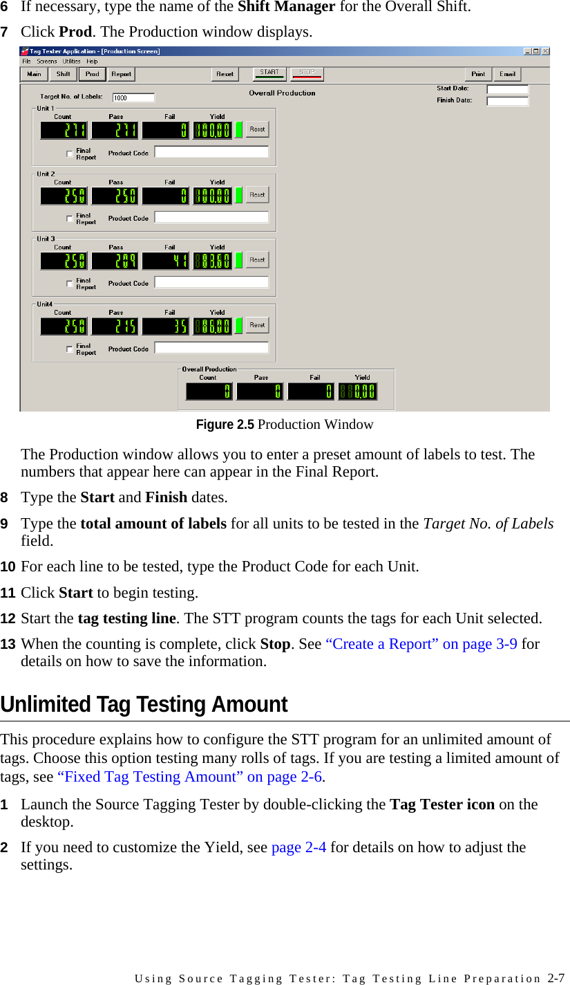
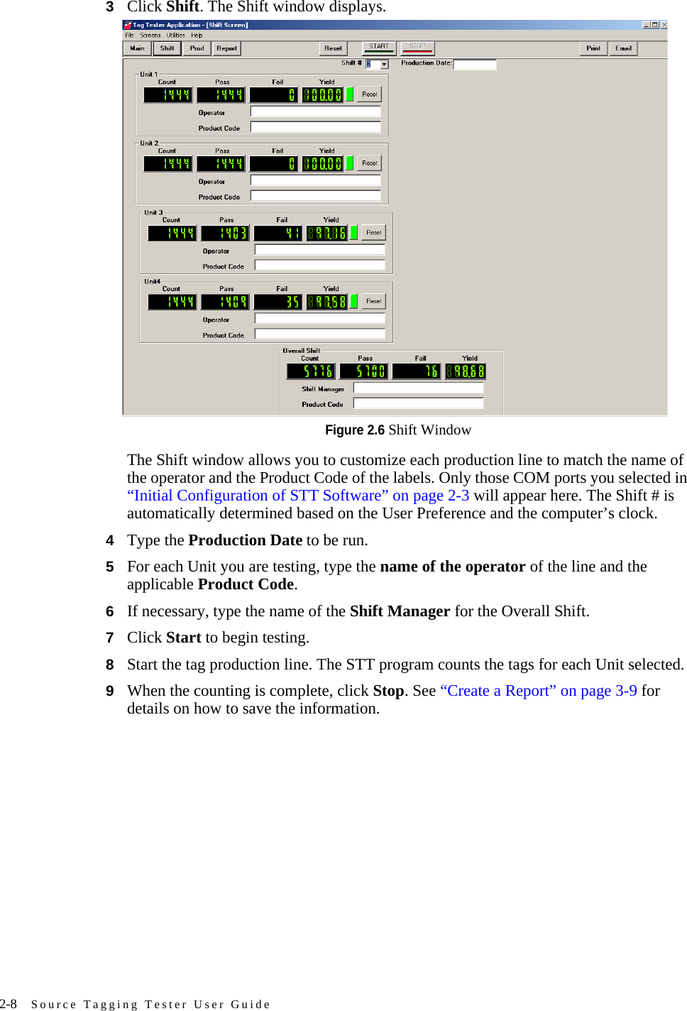
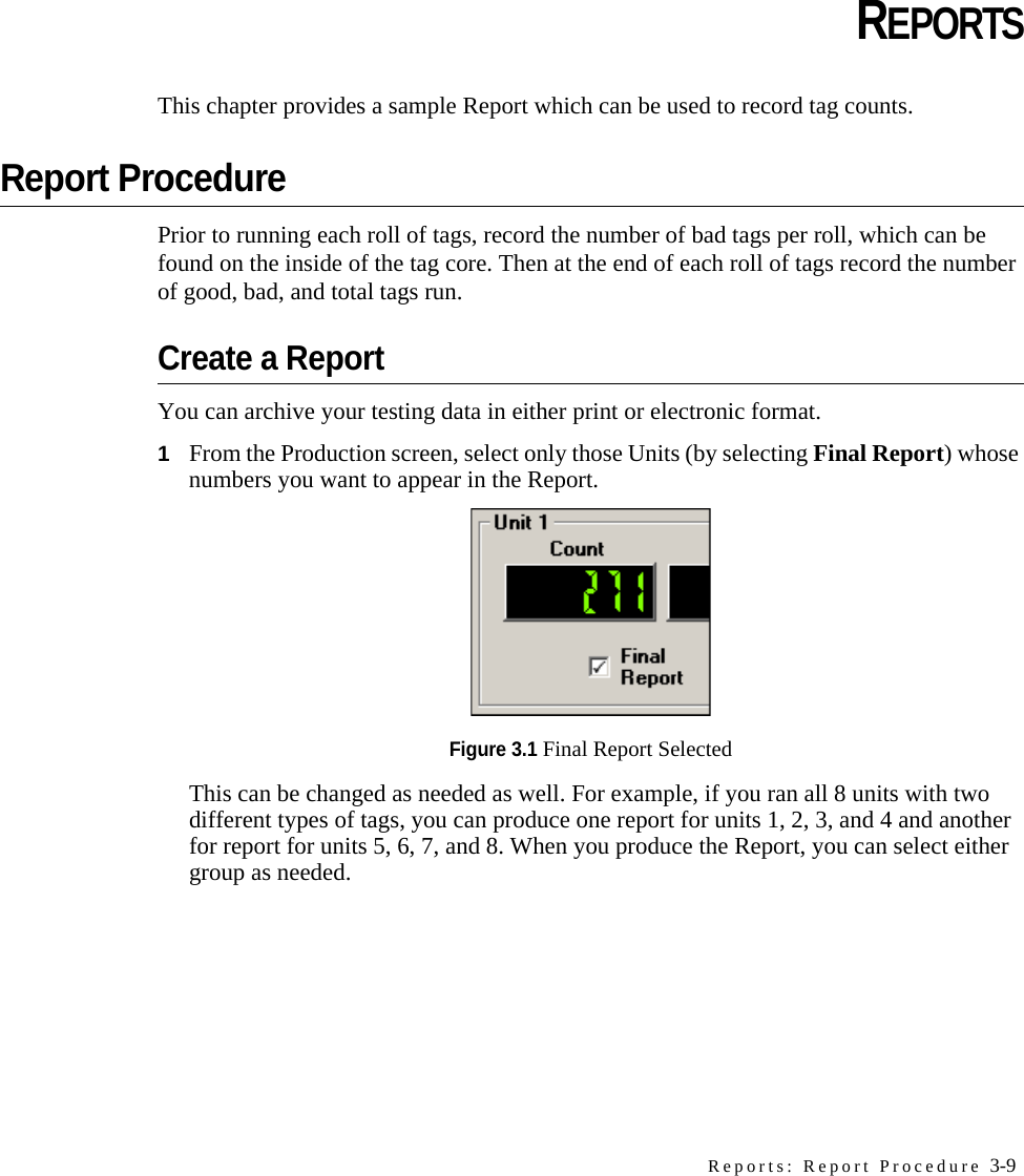
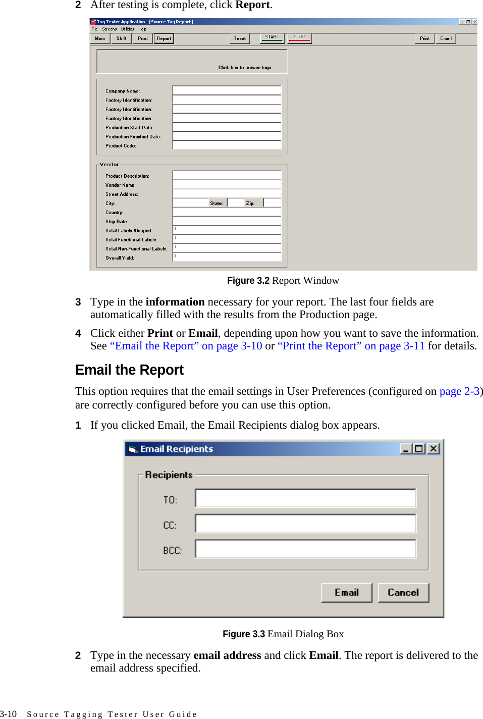
User Manual
Discussion / Help
Navigation