Checkpoint Systems OSTT RF LABEL VERIFIVCATION DEVICE User Manual Source Tagging Tester User Guide
Checkpoint Systems Inc RF LABEL VERIFIVCATION DEVICE Source Tagging Tester User Guide
USERS MANUAL

P/N 7413286
Source Tagging
. . . . .
. . . . . . . . . . . . . . . . . . . . . . . . . . . . . . . . . . .
Tester
User Guide
Version 1.0
ii
Published by:
Checkpoint Systems Inc.
101 Wolf Drive
Thorofare, NJ 08086
This manual refers to the Source Tagging Tester unit, Version 1.0.
Document revision information
Source Tagging Tester
Part Number: 7413286
Trademarks Copyright and Warranty Information
Checkpoint Systems, Inc. are registered trademarks of Checkpoint Systems, Inc.
Microsoft, Windows, and Windows XP are either registered trademarks or trademarks of Microsoft
Corporation in the United States
Other product and company names herein may be trademarks of their respective owners.
The information in this manual is subject to change without notice.
Because of the changing nature of this product information presented in the Installation Manual,
Checkpoint Systems, Inc. is not liable for any omissions, misstatements, or other errors of
information.
The information presented in the Installation Manual may not be copied, used or disclosed to others
for the purpose of procurement or manufacturing without the written permission of Checkpoint
Systems, Inc. This manual and the products discussed in this manual are the exclusive property of
Checkpoint Systems Inc. Copyright laws of the United States protect all information and products.
Copyright © 2005 by Checkpoint Systems, Inc. All rights reserved.
Rev Description Date Author
1.0 Initial Draft 11/10/2005 M. Reeves
iii Source Tagging Tester User Guide
Contact Information
USA
Checkpoint Systems, Inc.
101 Wolf Drive
Thorofare, NJ 08086 USA
http://www.checkpt.com
Technical Assistance/Service Requests: 800-253-7580
FAX: 856-384-2328
Europe
Checkpoint Systems International GmbH
Von-Humboldt-Strasse 10
Heppenheim
Hessen
64 646
Germany
+49 6252 798 300
Document Conventions
Warning This is a Warning icon. When it appears, the corresponding text indicates a cautionary statement
which you must abide by.
Caution This is a Caution icon. When it appears, the corresponding text indicates a cautionary statement
which you must abide by.
Note This is a Tip icon. When it appears, the corresponding text indicates a helpful note or tip when using
the feature.
The following usage conventions are used throughout the manual.
Button Name - This describes a button or selection on the screen. For example, the
<DONE> button is represented in this document as Done.
Key Name - This describes a keystroke on a keyboard. For example Ctrl represents the
control key.

iv
Regulatory Statement
Important Information to our Users in North America
FCC Regulatory Compliance Statement
Checkpoint Systems, Inc. offers certain Electronic Article Surveillance (EAS) products that have been FCC
certified or verified to 47 CFR Part 15, Subparts B/C and/or 47 CFR Part 18. Appropriately, one of the
following labels will apply to the approval:
NOTE: This equipment has been tested and found to comply with the limits for a Class A digital device,
pursuant to part 15 of the FCC Rules. These limits are designed to provide reasonable protection against
harmful interference when the equipment is operated in a commercial environment. This equipment
generates, uses, and can radiate radio frequency energy and, if not installed and used in accordance with the
instruction manual, may cause harmful interference to radio communications. Operation of this equipment
in a residential area is likely to cause harmful interference in which case the user will be required to correct
the interference at his own expense.
- OR -
This device complies with part 15 of the FCC Rules. Operation is subject to the following two conditions:
(1) This device may not cause harmful interference, and (2) this device must accept any interference
received, including interference that may cause undesired operation.
- OR -
NOTE: This equipment has been tested and found to comply with the limits for a miscellaneous type ISM
device, pursuant to part 18 of the FCC Rules. This equipment generates, uses, and can radiate radio
frequency energy and, if not installed and used in accordance with the instruction manual, may cause
harmful interference to radio communications. However, there is no guarantee that interference will not
occur in a particular installation. If this equipment does cause harmful interference to radio communications
reception, which can be determined by turning the equipment off and on, please contact Checkpoint
Systems, Inc. at (800) 257-5540 for further assistance.
Equipment Safety Compliance Statement
WARNING
: Changes or modifications to Checkpoint’s EAS equipment not expressly approved by the
party responsible for assuring compliance could void the user’s authority to operate the equipment in a safe
or otherwise regulatory compliant manner.

v Source Tagging Tester User Guide
Important Information to our Users in Europe
CE Compliance Statement
Where applicable, Checkpoint Systems, Inc. offers certain Electronic Article Surveillance (EAS) products
that have CE Declarations of Conformity to Council Directive(s) EMC 89/336/EEC, LVD 73/23/EEC, and
R&TTE 99/5/EC Radio and Telecommunications Terminal Equipment, as amended by 92/31/EEC and 93/
68/EEC.
System Electromagnetic Compatibility (EMC), has been tested and notified through Spectrum Management
Authorities using accredited laboratories and, in a few cases, EC type examination certified through a
Notified Body using Competent Body laboratories in Europe, whereby, conformity is declared to voluntary
accepted European Telecommunications Standards Institute (ETSI) standards EN 301 489 and EN 300 330.
In other cases, conformity is declared to the generic emission and immunity standards EN 50081-1 / EN
55022 / EN 50082-1 and EN 55024.
NOTE: Certain Checkpoint EAS equipment has been tested and found to conform with the CE emission and
immunity requirements in Europe. This equipment generates, uses, and can radiate radio frequency energy
and, if not installed and used in accordance with the instruction manual, may cause harmful interference to
radio communications. Under unusual circumstances, interference from external sources may temporarily
degrade the system performance. However, there is no guarantee that interference will not occur in a
particular installation. If this equipment experiences frequent interference from external sources or does
cause harmful interference to radio communications reception, which can be determined by turning the
equipment off and on, please contact a Checkpoint representative for further assistance.
Equipment Safety Compliance Statement
Checkpoint’s Electronic Article Surveillance (EAS) products have been designed for safeness during
normal use and, where applicable, certain components of the system or accessory sub-assemblies have been
declared safe according to the European Low Voltage Directive (LVD) by being certified, listed, or
recognized in accordance with one or more of the following European safety standards; EN 60950-1
(Amendments 1 & 2), EN60742, and EN50364. Additional approvals may be pending.
WARNING
: Changes or modifications to Checkpoint’s EAS equipment not expressly approved by the
party responsible for assuring compliance could void the user’s authority to operate the equipment in a safe
or otherwise regulatory compliant manner.

vi
Contact Information............................................................................................................................................ i-iii
Document Conventions...................................................................................................................................... i-iii
Regulatory Statement......................................................................................................................................... i-iv
Introduction..............................................................................................................................................1-1
Sample Layout Diagram....................................................................................................................... 1-2
Using Source Tagging Tester.................................................................................................................2-3
Initial Configuration of STT Software.................................................................................................... 2-3
Tag Testing Line Preparation................................................................................................................ 2-6
Fixed Tag Testing Amount................................................................................................................................. 2-6
Unlimited Tag Testing Amount........................................................................................................................... 2-7
Reports......................................................................................................................................................3-9
Report Procedure................................................................................................................................. 3-9
Create a Report ................................................................................................................................................ 3-9
Email the Report ............................................................................................................................................................... 3-10
Print the Report..................................................................................................................................................................3-11
Sample Report ................................................................................................................................... 3-12
Table of Contents

Introduction: 1-1
CHAPTER
C
HAPTER
0
I
NTRODUCTION
The Checkpoint Source Tagging Tester is designed to help Source Tagging Customers test
and verify Checkpoint labels in real time. The Source Tagging Tester tests every series of
Checkpoint labels and comes equipped with a counter mechanism that records the number
of good, bad, and total Checkpoint labels run on the production line.
The customer records the number of good, bad, and total number of Checkpoint labels
before resetting the counters. Each individual counter comes equipped with a manual hard
reset button, enabling the customer to reset the counters.
This user guide contains the following information:
• Introduction
• Configuring and Using the Source Tagging Tester
• Report Generation
1-2 Source Tagging Tester User Guide
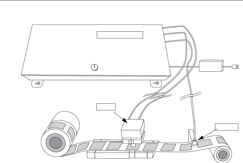
Sample Layout Diagram
The following diagram illustrates a sample installation of the Source Tagging Tester. Your
installation is entirely custom and dependent upon your individual requirements.
Figure 1.1
Sample Layout
Source Tagging Tester
Photo Eye
Antenna
Using Source Tagging Tester: Initial Configuration of STT Software 2-3
CHAPTER
C
HAPTER
0
U
SING
S
OURCE
T
AGGING
T
ESTER
This chapter instructs how to use the Source Tagging Tester software.
Initial Configuration of STT Software
Before testing starts, the software must be configured for use.
1Launch the Source Tagging Tester by double-clicking the Tag Tester icon on the
desktop.
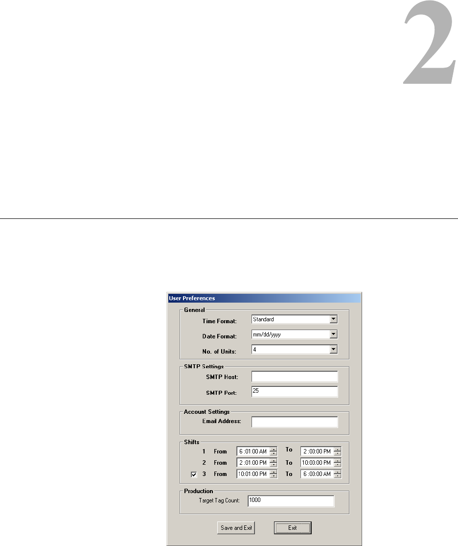
2Click File > User Preferences to access the User Preferences.
Figure 2.1
User Preferences
2-4 Source Tagging Tester User Guide
3If not using email, the SMTP and Email fields can be ignored. Type in the following
information to customize the software for the production line:
4Once complete, click Save and Exit to save the information. Otherwise, click Exit to
exit without saving your changes.
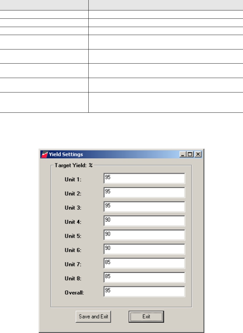
5Next, click File > Yield Settings to access Yield Settings.
Figure 2.2
Yield Settings
Table 2.1
User Preferences
Field Description
Time Format Select either Standard or Military time.
Date Format Select the type of date format.
No. of Units Select the number of production lines to be monitored.
SMTP Host If necessary, enter the SMTP Host information. Contact IT for the
information.
SMTP Port If necessary, enter the SMTP Port information. Contact IT for the
information.
Email Address If necessary, type the email address to which the program sends
results.
Shifts Select the time for each shift. You cannot leave more than a 10
minute interval between each shift.
Target Tag Count Type the number of tags that are to be tested for each run. Once the
count has reached the limit specified here, the program stops
counting.
Using Source Tagging Tester: Initial Configuration of STT Software 2-5
The yield is the amount of good tags you wish to achieve for each line and each roll.
For example, in Unit 1 above, the program is set for 95% yield, which only allows for
5% of tags to fail.
6Type the yield you wish to maintain for each unit you are programming. If not using all
units (as programmed in step 3), leave the default value in the field.
7In the Overall field, type the final successful yield for all of the units.
8Once complete, click Save and Exit to save the information. Otherwise, click Exit to
exit without saving your changes.
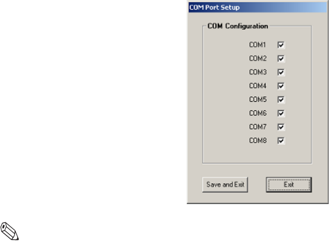
9Next, click File > Yield COM Setup to access COM Port Setup.
Figure 2.3
COM Port Setup
Note: Multiple COM Ports refers to the usage of an RS232/COM port expansion unit.
10 Select only the COM ports you will use for tag testing. Otherwise, leave the
checkboxes blank. The COM ports must be selected sequentially and COM1 must
always be selected, as that is the computer itself. COM2-COM8 refers to the COM port
hub.
11 Once complete, click Save and Exit to save the information. Otherwise, click Exit to
exit without saving your changes.
2-6 Source Tagging Tester User Guide
Tag Testing Line Preparation
This procedure assumes that all the initial configuration of the software has been
completed. If not, see “Initial Configuration of STT Software” on page 2-3 for details.
Before configuring the software, the tags must be ready to be run on the production line.
Follow your company’s procedures for the correct installation method.
Fixed Tag Testing Amount
This procedure explains how to configure the STT program for a finite amount of tags.
Choose this option when testing a set number of tags for a particular product code, for
example 1,000 tags for a line of shirts. If you are testing an unlimited amount of tags, see
“Unlimited Tag Testing Amount” on page 2-7.
1Launch the Source Tagging Tester by double-clicking the Tag Tester icon on the
desktop.
2If you need to customize the Yield, see page 2-4 for details on how to adjust the
settings.
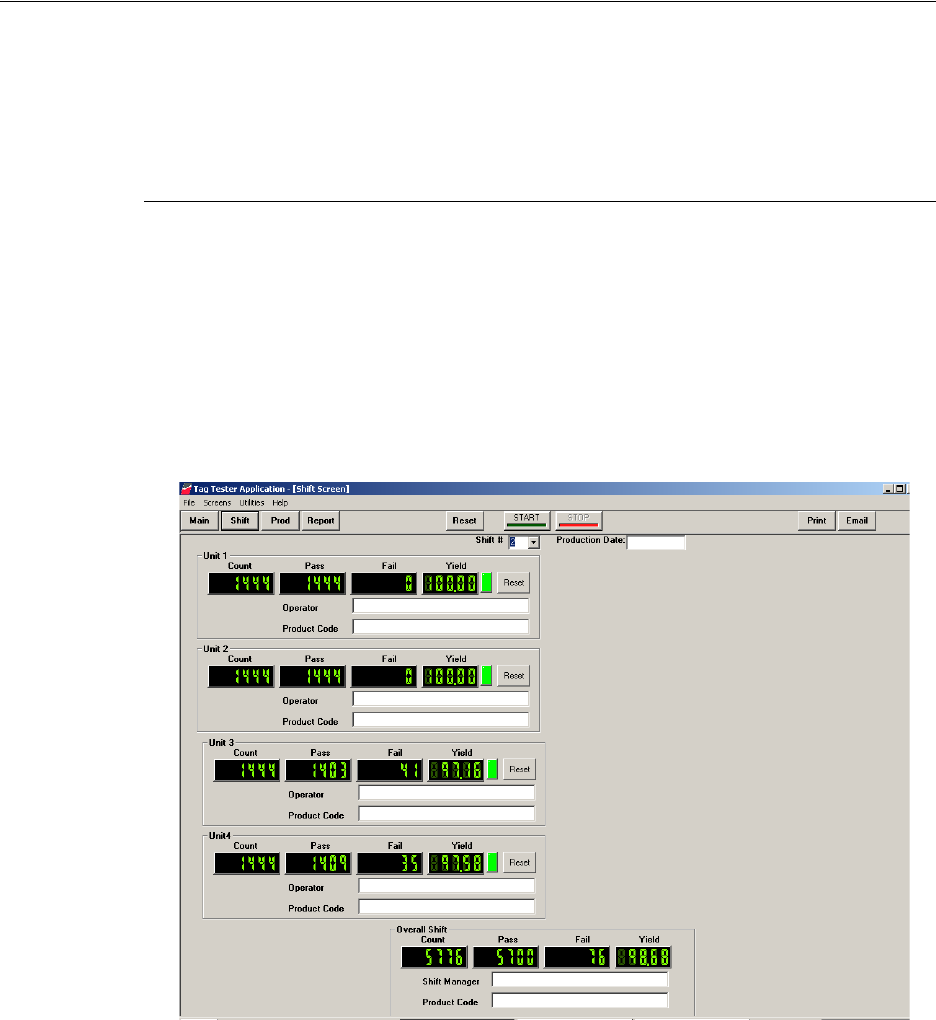
3Click Shift. The Shift window displays.
Figure 2.4
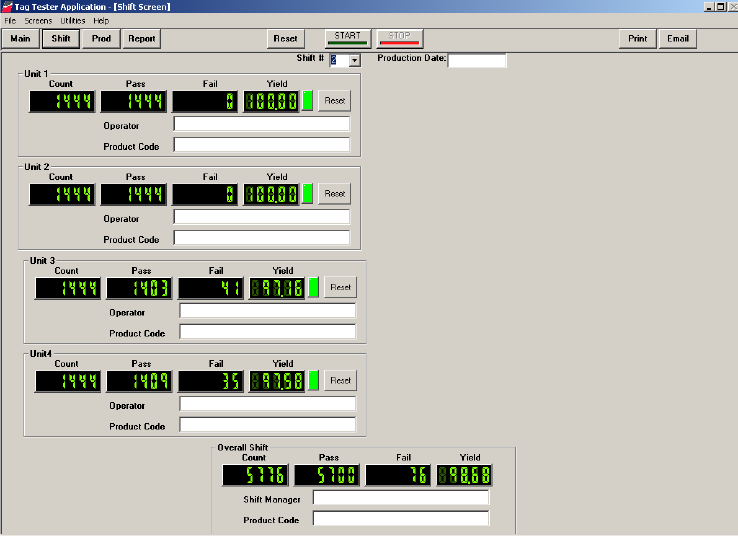
Shift Window
The Shift window allows you to customize each production line to match the name of
the operator and the Product Code of the labels. The Shift # is automatically
determined based on the User Preference and the computer’s clock.
4Type the Production Date to be run.
5For each Unit you are testing, type the name of the operator of the line and the
applicable Product Code.
Using Source Tagging Tester: Tag Testing Line Preparation 2-7
6If necessary, type the name of the Shift Manager for the Overall Shift.
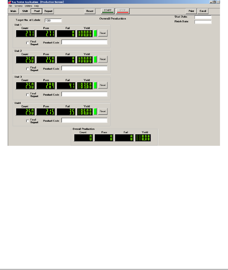
7Click Prod. The Production window displays.
Figure 2.5
Production Window
The Production window allows you to enter a preset amount of labels to test. The
numbers that appear here can appear in the Final Report.
8Type the Start and Finish dates.
9Type the total amount of labels for all units to be tested in the Target No. of Labels
field.
10 For each line to be tested, type the Product Code for each Unit.
11 Click Start to begin testing.
12 Start the tag testing line. The STT program counts the tags for each Unit selected.
13 When the counting is complete, click Stop. See “Create a Report” on page 3-9 for
details on how to save the information.
Unlimited Tag Testing Amount
This procedure explains how to configure the STT program for an unlimited amount of
tags. Choose this option testing many rolls of tags. If you are testing a limited amount of
tags, see “Fixed Tag Testing Amount” on page 2-6.
1Launch the Source Tagging Tester by double-clicking the Tag Tester icon on the
desktop.
2If you need to customize the Yield, see page 2-4 for details on how to adjust the
settings.
2-8 Source Tagging Tester User Guide
3Click Shift. The Shift window displays.
Figure 2.6
Shift Window
The Shift window allows you to customize each production line to match the name of
the operator and the Product Code of the labels. Only those COM ports you selected in
“Initial Configuration of STT Software” on page 2-3 will appear here. The Shift # is
automatically determined based on the User Preference and the computer’s clock.
4Type the Production Date to be run.
5For each Unit you are testing, type the name of the operator of the line and the
applicable Product Code.
6If necessary, type the name of the Shift Manager for the Overall Shift.
7Click Start to begin testing.
8Start the tag production line. The STT program counts the tags for each Unit selected.
9When the counting is complete, click Stop. See “Create a Report” on page 3-9 for
details on how to save the information.
Reports: Report Procedure 3-9
CHAPTER
C
HAPTER
0
R
EPORTS
This chapter provides a sample Report which can be used to record tag counts.
Report Procedure
Prior to running each roll of tags, record the number of bad tags per roll, which can be
found on the inside of the tag core. Then at the end of each roll of tags record the number
of good, bad, and total tags run.
Create a Report
You can archive your testing data in either print or electronic format.
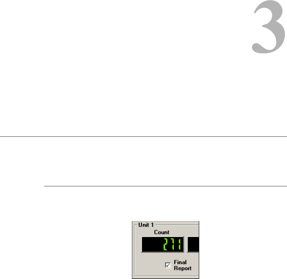
1From the Production screen, select only those Units (by selecting Final Report) whose
numbers you want to appear in the Report.
Figure 3.1
Final Report Selected
This can be changed as needed as well. For example, if you ran all 8 units with two
different types of tags, you can produce one report for units 1, 2, 3, and 4 and another
for report for units 5, 6, 7, and 8. When you produce the Report, you can select either
group as needed.
3-10 Source Tagging Tester User Guide
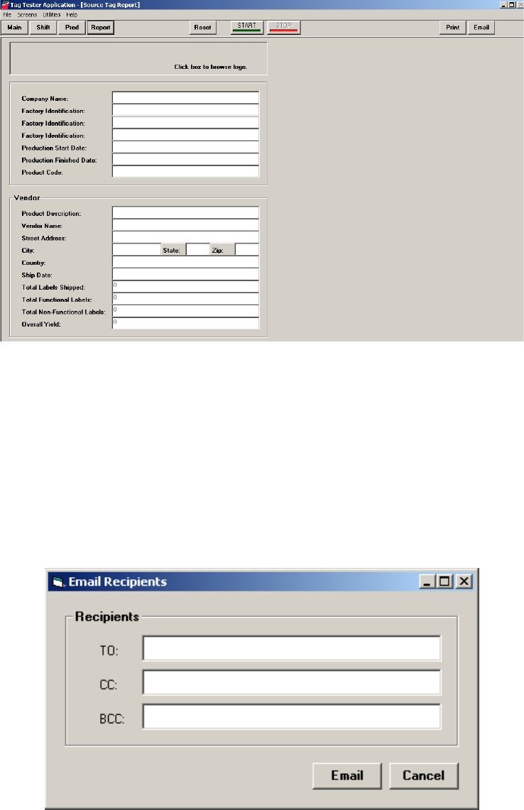
2After testing is complete, click Report.
Figure 3.2
Report Window
3Type in the information necessary for your report. The last four fields are
automatically filled with the results from the Production page.
4Click either Print or Email, depending upon how you want to save the information.
See “Email the Report” on page 3-10 or “Print the Report” on page 3-11 for details.
Email the Report
This option requires that the email settings in User Preferences (configured on page 2-3)
are correctly configured before you can use this option.
1If you clicked Email, the Email Recipients dialog box appears.
Figure 3.3
Email Dialog Box
2Type in the necessary email address and click Email. The report is delivered to the
email address specified.
Reports: Report Procedure 3-11
Print the Report
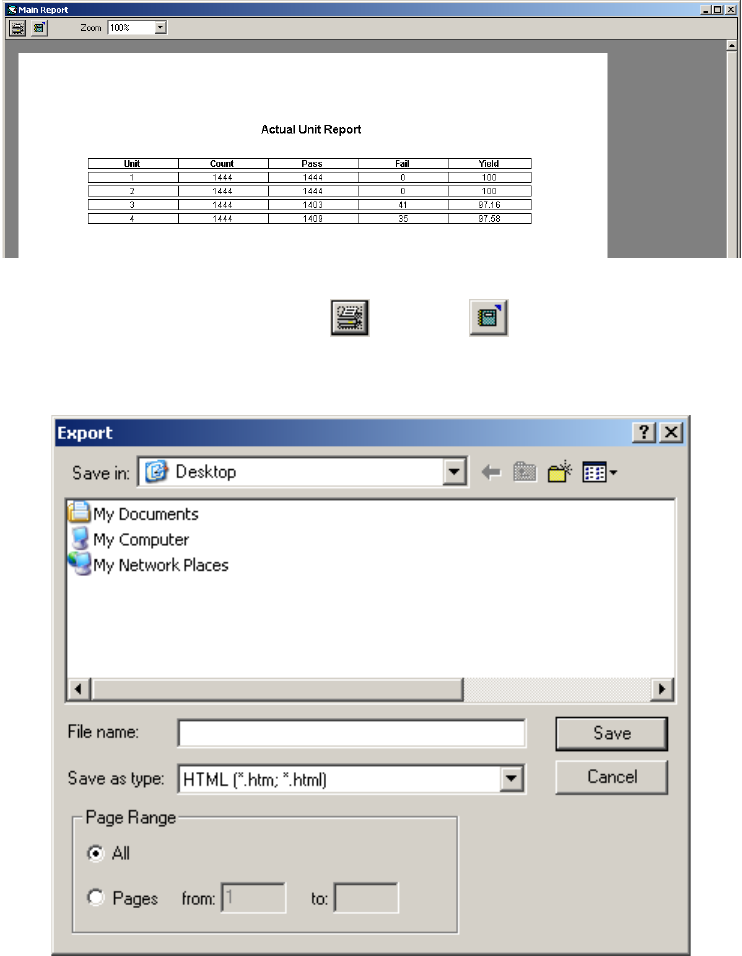
1If you clicked Print, a sample of the Report displays.
Figure 3.4
Report Sample
2At the top left, click either the Print or Export button.
3If you clicked Print, the Report is sent to the printer.
4If you clicked Export, the Export dialog box appears.
Figure 3.5
Export Dialog Box
5Select a destination for the file, type a file name, and select the file type (HTML or
TXT) for the Report and click Save.
3-12 Source Tagging Tester User Guide
Sample Report
You can use this sample report to record your results if desired.
Table 3.1
Checkpoint Source Tagging Tester Report
Roll # Factory Bad Labels Bad Production
Labels Good Production
Labels Total # of Production
Labels