Chuango Security Technology P900 P.I.R. Motion Detector User Manual 900 EN 1212 2 0
Chuango Security Technology Corporation P.I.R. Motion Detector 900 EN 1212 2 0
User Manual
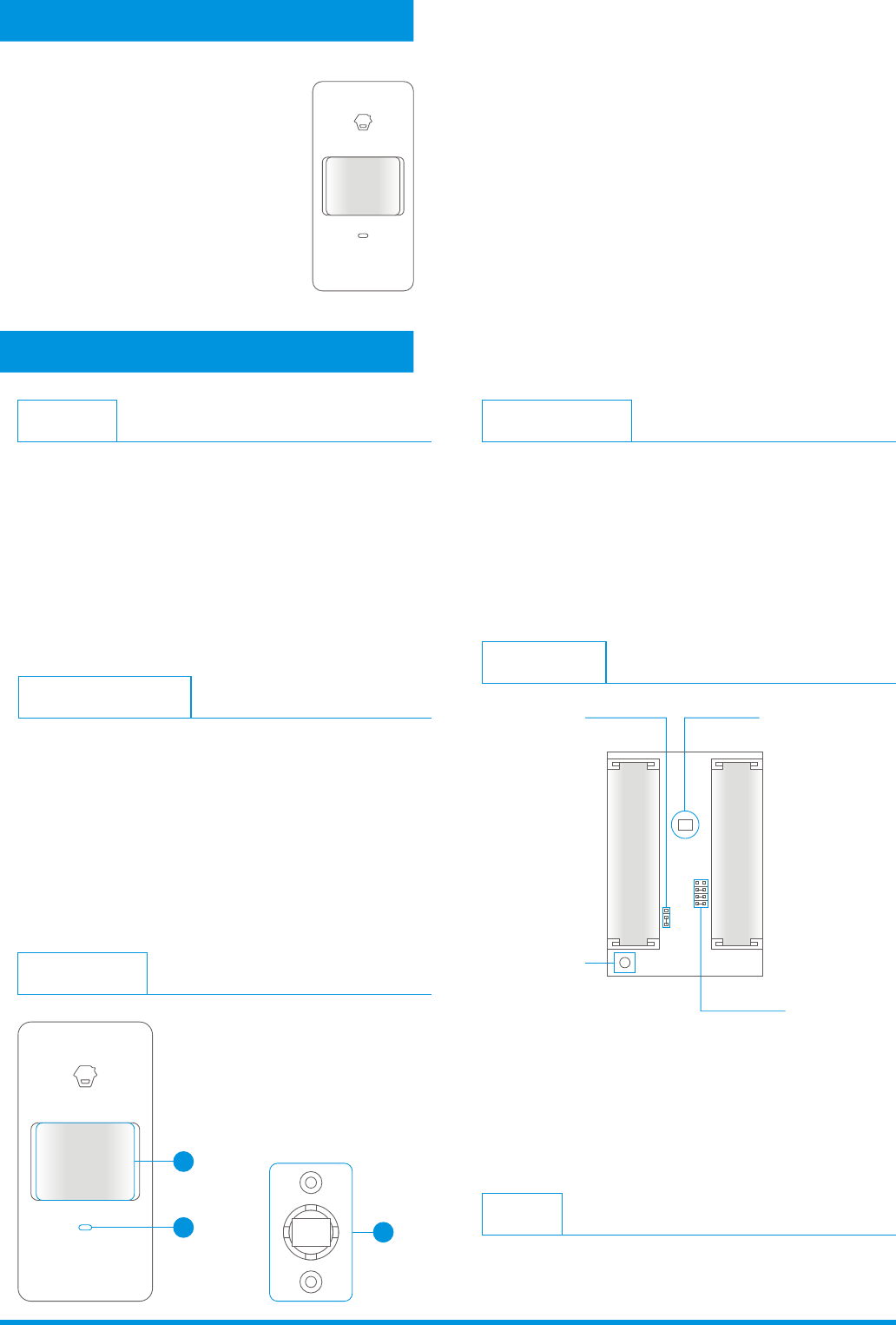
Appearance
1
23
1. Detection window
2. LED indicator
3. Bracket
PIR-900
Operation Manual
Wireless PIR Motion Detector
(For Indoor Use)
Infrared sensor:
Tamper switch:
It detects the infrared rays released by
human body motion, please don’t touch the surface and
always keep it clean.
Once the case is opened in working state,
the tamper switch will be triggered and then generates
an alarm signal.
PCB Layout
Infrared sensor
Tamper switch
Zone setting
AA 1.5V LR6
AA 1.5V LR6
LED ON / OFF
Usage
Open the case and remove the battery activation strip to
activate batteries. It will start self-testing for one minute.
LED Indication
Flash conti nuously:
Flash once:
Flash twice:
Flash once per 3 seconds:
Under the self-testing state.
Intruder is detec ted.
Self-testing is finished, enters the worki ng mode.
Under voltage indication, please
change the batt eries immediately.(User will get alert SMS about
the low batt ery if the PIR detec tor is connect ed to the GSM
alarm system.)
1. This device complies with Part 15 of the FCC Rules.
Operation is subject to the following two conditions:
(1) This device may not cause harmful interference, and
(2) This device must accept any interference received,
including interference that may cause undesired operation.
2. Changes or modifications not expressly approved by the
party responsible for compliance could void the user's
authority to operate the equipment.
Features
FCC Statement
PIR-900 is a high performance wireless P.I.R. motion detector.
It consists of digital dual-core fuzzy logic infrared control
chip and intelligent analysis which effectively identify
interference signals from body movement signals and reduce
false alarm rate. With automatic temperature compensation
and anti-air turbulence technology, it easily adapts to
environmental changes. The detector also has the advantages
of energy saving, reliability and easy installation.
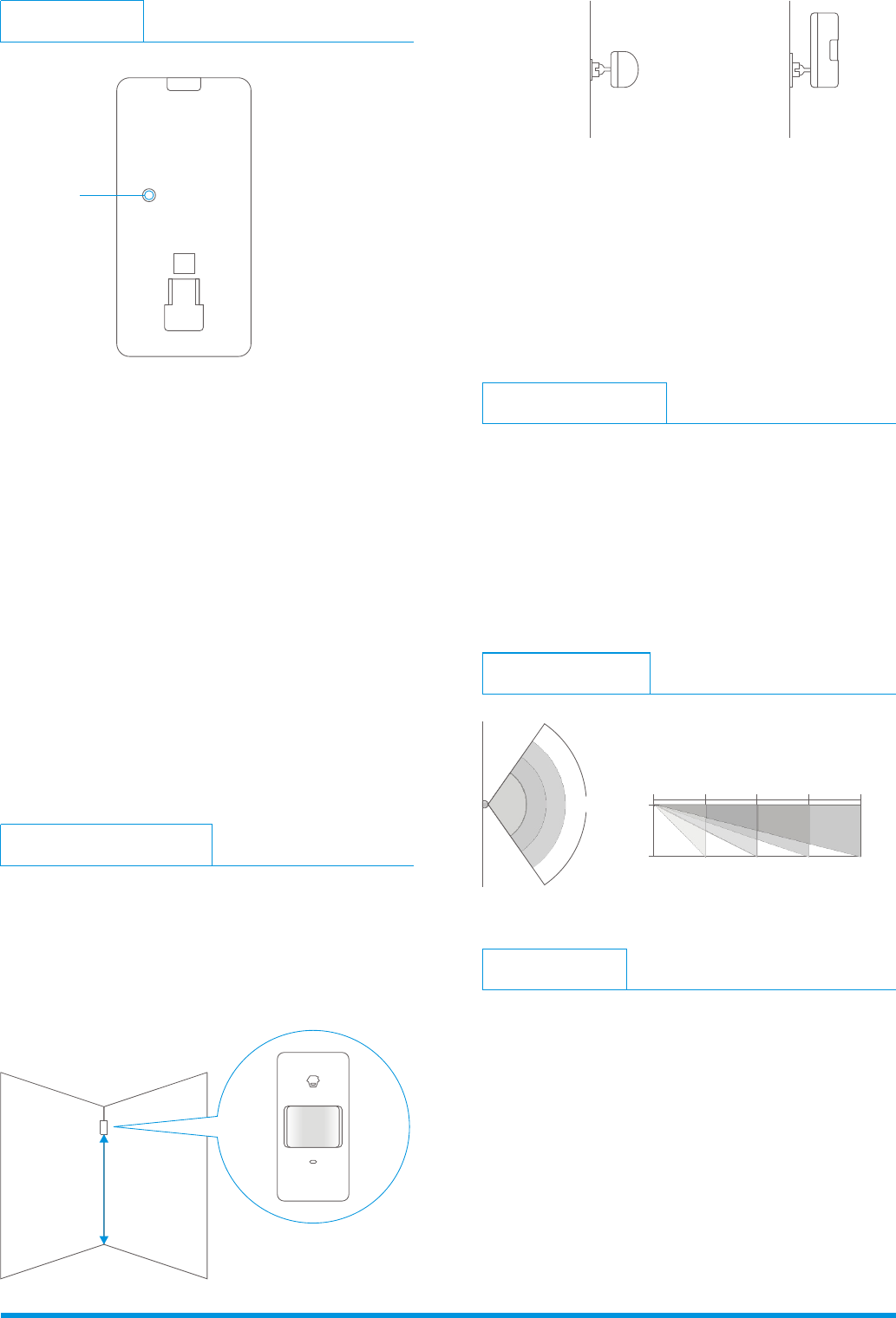
Fix the bracket on the wall with screws and attach the
detector to the bracket. Adjust installation height
or bracket to change the detection distance and angle.
It is recommended to mount it at the height of 2m from
the ground.
The detector is more sensitive to the cross movement
than to the vertical movement, so the performance of
detector is best when the detection direction is vertical
to the walking direction of people.
Ver: 900-EN-1212-2.0
2m
Installation & Notices
Avoid mounting the detector close to windows, air
conditioner, heater, refrigerator, oven, sunshine and places
where the temperature changes fast or the air stream flows
frequently. If two detectors are installed in the same
detection scope, please adjust the location to avoid
interference and false alarm.
Ground
Top view Side view
In worki ng state, if the sensor is triggered
more than twice within 3 minutes, it will enter sleeping
mode to save power. After no movement within next 3
minutes, the sens or goes back to the worki ng mode.
Press the connect key on the
alarm panel , and then press the test butt on of the sensor
twice to send alarm signal . When one beep is heard, they
are connect ed. To check if they are connect ed succ essfully,
arm the system, and trigger the sensor agai n, if there is an
alarming, the connect ion is succ essful.
Working mode:
Connect to alarm panel :
Detection Scope
2m 4m 6m 8m0m
0m
2m
110°
Top view Side view
Testing (Walk Test)
A. After installation, power on the detector. After one minute
self-testing, press the test button, walk in the scope (from
left to right or from right to left) and watch the LED
indicator to make sure the detector is working.
B. The LED indicator flashes once when body movement is
detected.
C. Adjust the detector angle accordingly to achieve the best
detection effect.
Mode Setting
Testing mode: After self-testing, press the test button,
the sensor enters testing mode, and detects once ever y
10 seconds. After 3 minutes, the LED flashes twice, and
the sensor enters the worki ng mode.
Test Button
Specifications
Power supply
Static current
Alarm current
Detection scope
Transmitting distance
Radio frequency
Housing material
Operation Condition
Detector dimensions (L x W x H)
Bracket dimensions (L x W x H)
DC 3V (AA 1.5V LR6 Battery x 2 pcs)
≤ 50uA
≤ 9.5mA
8m/110°
≤ 80m (in open area)
ABS plastic
Temperature: -10°C~55°C
Relative humidity: ≤80% (non-condensing)
108 x 52 x 36.8 mm
52 x 30 x 26.5 mm
315.8599MHz