Chung Hsin Electric and Machinery Mfg VSS-5830P 5.8 GHz Wireless Video Server with 433.92MHz transmitter User Manual VSS 5830 1A
Chung-Hsin Electric & Machinery Mfg. corp. 5.8 GHz Wireless Video Server with 433.92MHz transmitter VSS 5830 1A
User manual


2
About this document
This
software quick
manual
is
intended
for
u
ser of
5.8
GHz
Wireless
Video
Server
.
The
default
IP
setting
of
Wireless
Video
Server
is
DHCP
.
Please
refer
to
user
manual
of
Wireless
Video
Server,
if
there
is
not
DHCP
Server
on
your
network.
IMPORTANT
Check
PC
specification
re
qui
r
ement
s
Check
OS
platform
requirements
Install
IPSurveillance
Application
Software
be
for
e
you
s
t
ar
t
wo
rk
ing
with
Wireless
Video
Server
.
Read
special
note
s
and
important
con
f
iguration
information.

3
TABLE OF CONTENTS
1. PRODUCT OVERVIEW ........................................................................................ 5
2. PRODUCT CD ......................................................................................................... 6
3. BEFORE YOU INSTALL SOFTWARE............................................................... 6
4. LANGUAGE SUPPORT......................................................................................... 6
5. HOUSING and CONNECTORS ............................................................................ 7
Front
side
look ....................................................................................................... 7
Back
side
look ........................................................................................................ 9
6. FIRST TIME USE INSTRUCTIONS (read carefully) ...................................... 11
INSTALL
IPSURVEILLANCE
APPLICATION
SOFTWARE
......................... 11
WHICH
BROWSER
TO
USE?
............................................................................ 11
POWER
ON
Wireless
Video
Server
.................................................................... 11
CONNECTING
TO
NETWORK
......................................................................... 11
FACTORY
SETTING
-
INITIAL
IP
ADDRESS
................................................ 11
USING
IPSCAN
.................................................................................................. 12
CHANGE
NETWORK
SETTINGS
BY
IPSCAN
............................................... 14
7. ACCESS Wireless Video Server........................................................................... 16
BROWSER
.......................................................................................................... 16
INSTALL
AND
RUN
ACTIVEX
CONTROL
.................................................... 17
INITIAL
USERNAME
&
PASSWORD
.............................................................. 18
VIEWING
AND
OPERATTING
PAGE
............................................................. 18
CONTROL
PANEL
SETTINGS
......................................................................... 20
8. WEB INTERFACE SETTINGS........................................................................... 21
STATUS
............................................................................................................... 22
NETWORK
.......................................................................................................... 23
STATIC IP.................................................................................................... 23
DYNAMIC IP .............................................................................................. 24
PPPoE SETTINGS....................................................................................... 25
VIDEO
................................................................................................................. 26
VIDEO SETTINGS ..................................................................................... 26
COLOR SETTINGS .................................................................................... 28
VIDEO PREVIEW ...................................................................................... 28
MAX CLIENT LIMIT ................................................................................. 29
EVENT
RULE
..................................................................................................... 29
EVENTS HANDLED .................................................................................. 30
ACTIONS TRIGGERED............................................................................. 31
4
RULE LISTS - ADDING/DELETING........................................................ 31
MODIFYING RULE LISTS........................................................................ 31
CAPTURE
........................................................................................................... 32
DATE
&
TIME
.................................................................................................... 33
OSD
...................................................................................................................... 34
DWELL
MODE
SETUP
(ATUO-SCAN
MODE)
............................................... 35
PTZ
CONTROL
................................................................................................... 36
PORT
................................................................................................................... 36
DDNS
................................................................................................................... 38
SMTP/FTP
........................................................................................................... 39
E-MAIL – SMTP SETTINGS ..................................................................... 39
FTP SETTINGS ........................................................................................... 40
TRIGGER
SETUP
............................................................................................... 41
Digital INPUT.............................................................................................. 41
PERIODIC TIMER...................................................................................... 41
MOTION DETECTION .............................................................................. 42
Video Loss ................................................................................................... 44
PRE/POST
SETTING
.......................................................................................... 44
ACCOUNT
.......................................................................................................... 45
SECURITY
.......................................................................................................... 46
MAINTENANCE
................................................................................................. 48
9. FACTORY DEFAULT.......................................................................................... 49
10. REBOOT .............................................................................................................. 49
11. LOGOUT .............................................................................................................. 49
12. USB Config Port - FIRST TIME EXPERIENCE............................................. 50
SUPPORTED
OS
................................................................................................. 50
NO
SOFTWARE
INSTALLATION
REQUIRED
............................................... 50
STEPS
FOR
USING
USB
config
port
(Windows
XP
PC)
................................... 51
5
1. PRODUCT OVERVIEW
VSS-5830
is
the
first
5.8GHz
wireless
video
server.
By
installing
a
5.8GHz
transmitter
in
each
of
your
analog
camera,
and
a
built-in
8-channel
receiver
in
VSS-5830,
VSS-5830
can
connect
up
to
8
cameras
wirelessly
without
interference
from
all
devices
operating
from
2.4GHz,
such
as
Bluetooth
and
Wi-Fi.
VSS-5830
also
has
a
built-in
video
server
that
connects
to
the
internet,
enables
you
to
view
and
record
video
from
8
cameras
(one
at
a
time),
and
set
auto-scan
time
freely
(from
1-120
seconds)
on
each
channel
either
locally
or
over
the
internet.
Wirelessly
remote
control
PTZ
speed
dome
over
the
internet
and
remote
control
locally
features
are
also
available
with
additional
purchase.
You can set up PTZ module function that show in page 36
When you finish the set up function then the screen will display
Control manu as shown page 19

6
2. PRODUCT CD
Produ
c
t
CD
in
the
package
contains
the
fo
llowing:
IPSurveillance
Application
Softwa
re
NVR
management
softwa
re
¤
16CH
Live
View
/
Recording
/
Playback
User
Manuals
3. BEFORE YOU INSTALL SOFTWARE
PC
running
Microsoft
Windows
XP
Server
Pack
2
or
above
is
only
capable
of
running
IPSurveillance
Application
Software
software.
PLEASE
go
through
IPSurveillance
Application
Software
user
’
s
manual
be
f
ore
installation
to
check
f
urther
PC
requirements
in
order
to
en
sur
e
smooth
s
oftwa
re
op
er
atio
n.
4. LANGUAGE SUPPORT
ENGLISH
NOTE
IPSurveillance Application Software™ setup will auto-run when inserting
product CD. Pay attention to dialog box questions before you press OK button.
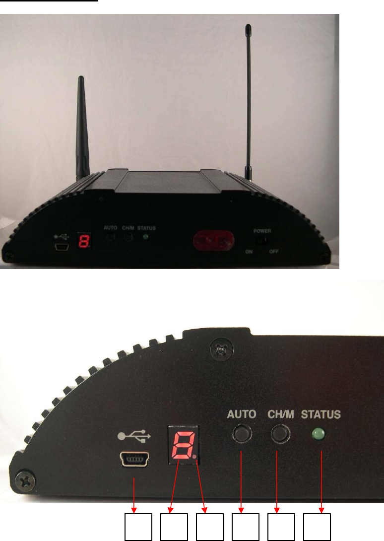
5. HOUSING and CONNECTORS
Front side
l
ook
1
2
3
4
5
6
1: miniUSB Port for configuration (for IP address setting only)
2: Channel or mode number display. This indicates mode number (Mode 1 ~ 9), if
it is flashing. Or, this indicates channel number (CH 1 ~ 8 for wireless receiver,
CH 9 for wire input), it is bright.
3: Fixed channel mode or auto-scan mode display. This indicates auto-scan mode,
7
if the dot display is bright. Or, this fixed channel mode, if the dot display is off.
4: Push button for changing fixed channel mode or auto-scan mode
5: Push button is for changing channel number, if it is at fixed channel mode. And,
it is for changing mode number, if it is auto-scan mode.
6: LED for System Status
7
8
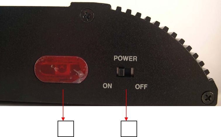
7: IR Receiver
8: Power switch
8
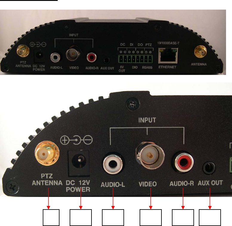
Back side
l
ook
9
10
11
12
13
14
9: SMA connector for wireless PTZ antenna. It disappears, if wireless PTZ is not
built in this device.
10: Power Jack for 8 ~ 32 VDC input
11: RCA connector for audio left input (CH 9)
12: BNC connector for video input (CH 9)
13: RCA connector for audio left input (CH 9)
14: A/V jack for audio and video output
9
10
15
16
17
18
19
20
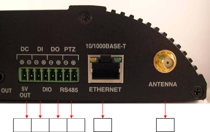
15: 5V DC output
16: Terminal block for digit input, if wireless PTZ is not built in this device. There
is no function, if wireless PTZ is built in this device.
17: Terminal block for digit output, if wireless PTZ is not built in this device.
There is no function, if wireless PTZ is built in this device.
18: Terminal block for RS-485, if wireless PTZ is not built in this device. There is
no function, if wireless PTZ is built in this device.
19: RJ-45 connector for Ethernet
20: SMA connector for 5.8 GHz antenna

11
6. FIRST TIME USE INSTRUCTIONS (read carefully)
INSTALL IPSURVEILLANCE APPLICATION SOFTWARE
Install
IPSurveillance
Application
Software
.
IPScan
is
a
s
o
f
twa
r
e
utility
to
f
ind
you
r wireless
video
s
e
r
ve
r
on
the
netwo
r
k
. I
t
i
s
a
pa
r
t
o
f
IPSurveillance
Application
Softwa
re.
WHICH BROWSER TO USE?
We
strongly
recommend
Micro
s
oft IE brow
ser
version 6
or
highe
r.
Mozilla
Fire
fo
x
and
simila
r
others
are
not
guaranteed
to
work
with
Wireless
Video
Server.
POWER ON Wireless Video Server
Power
on
video
server
by
using
powe
r
adapter
provided
in
the
product
package.
Connect
power
adapte
r
to
AC
s
ocket.
CONNECTING TO NETWORK
Connect
a
standard
CAT5
Ethe
rn
et
cable
to
R45
so
c
ket
on
Wireless
Video
Server
and
connect
other
end
to
you
r
netwo
r
k
hub/swit
ch.
Make
sure
the
PC
you
want
to
a
ccess
Wireless
Video
Server
is
on
the
same
netwo
r
k
domain
which
has
DHCP
server.
FACTORY SETTING - INITIAL IP ADDRESS
IP Address: DHCP
USING IPSCAN
IPScan
s
o
f
twa
r
e
i
s
the
qui
c
ke
s
t
way
to
make
s
u
r
e
we
c
an
f
ind
Wireless
Video
Server
on
yo
ur
network.
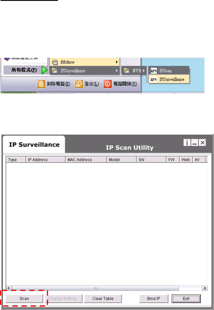
IPSurveillance
Application
Software
setup
will
install
two
applications.
You
can
see
a
s
shown
below
.
Select
IPScan.
The
following
window
appe
ars
a
f
te
r
you
select
“
IPScan
”
from
start
menu.
Pre
ss
Scan
button
to
list
the
I
P
and
MAC
addre
ss
table.
To
refresh,
press
Clear
Tab
l
e
and
pre
ss
Scan
agai
n.
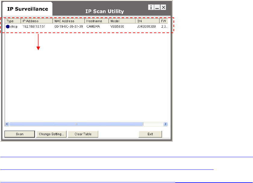
You
will
find
the
list
o
f I
P
and
MAC
add
ress
listed.
To
identify
yo
ur
Wireless
Video
Server
you
can
c
heck
the
label
f
o
r
MAC
add
r
e
ss.
To
quit
IPSca
n
anytime,
click
Ex
it.
12
Double right click
If you want to quickly open the IP you see on IPScan on your browser,
select an IP and do a “double right click” on your
mouse/touchpad. You can see the browser window open that IP.
13
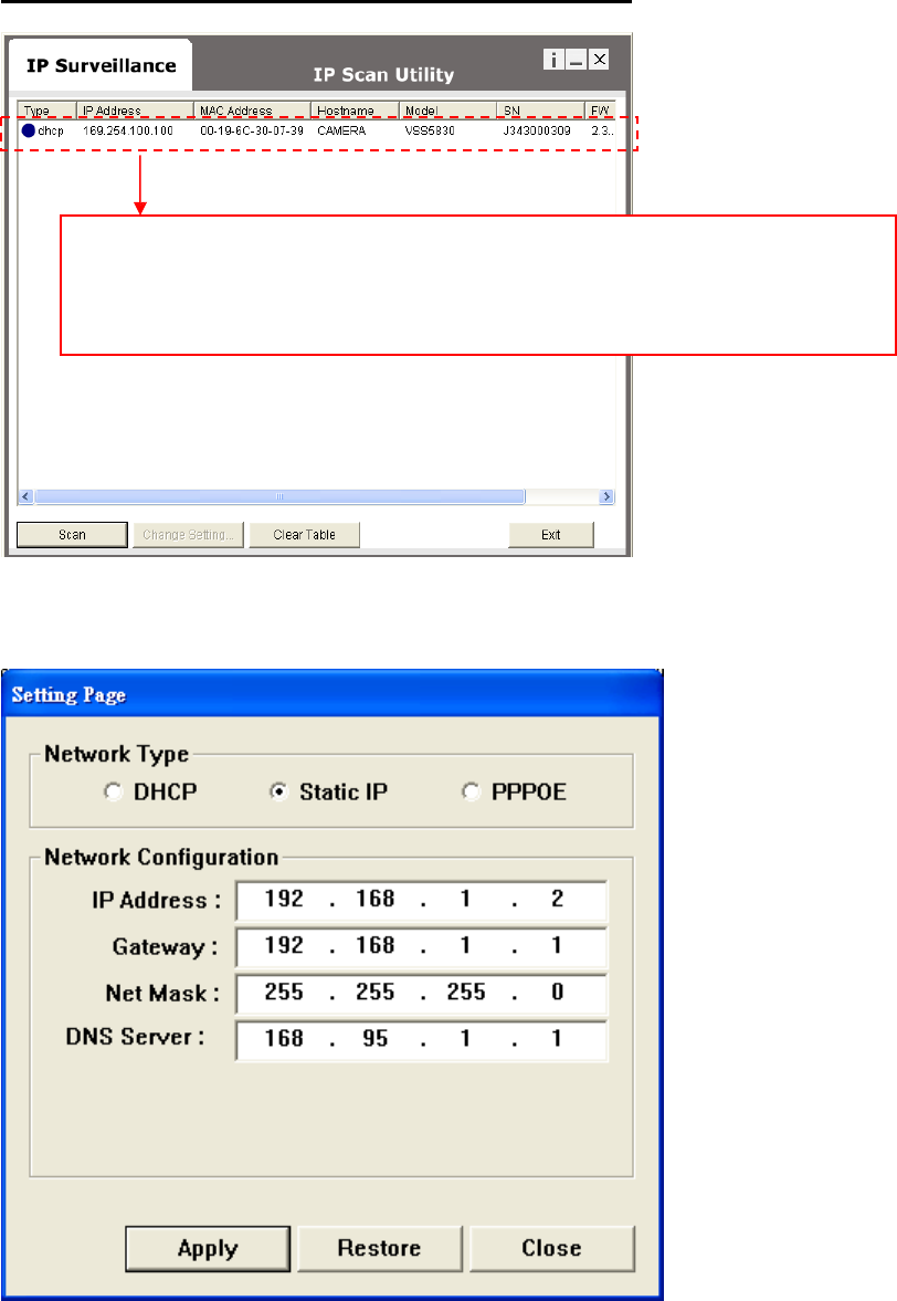
CHANGE NETWORK SETTINGS BY IPSCAN
The IP address is 169.254.100.100, if there is no DHCP
server on your network.
Double click to change network setting.
You
can
double
click
a
specific
I
P
add
ress
and
change
some
basic
netw
ork
paramete
rs.
A
dialog
box
will
appear
as
follow
s.
Change
any
settings
you
want
to
make
and
make
s
u
r
e
you
have
c
o
rr
e
c
t
values
in
all
fields.
Cli
c
k
Apply
.
Within
10
seconds,
the
dialog
box
should
disapp
ear
to
indicate
new
14
15
settings
are
accepted
and
being
applied
.
Wait
for
around
30
second
s,
before
trying
to
refres
h
I
P
list.
Click
Clea
r
Table
and
click
scan
agai
n.
You
should
be
able
to
find
MAC
addre
ss of
video
ser
v
er
und
er
new
I
P
addre
ss.
Wireless
Video
Server
is
online
on
you
r
network.
Use
ping
command
from
Window
s
command
prompt
to
double
check
if
IP
is
reachable.
To
quit
IPSca
n
anytime,
click
Ex
it.
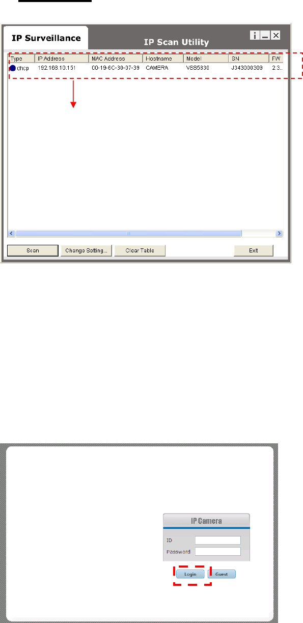
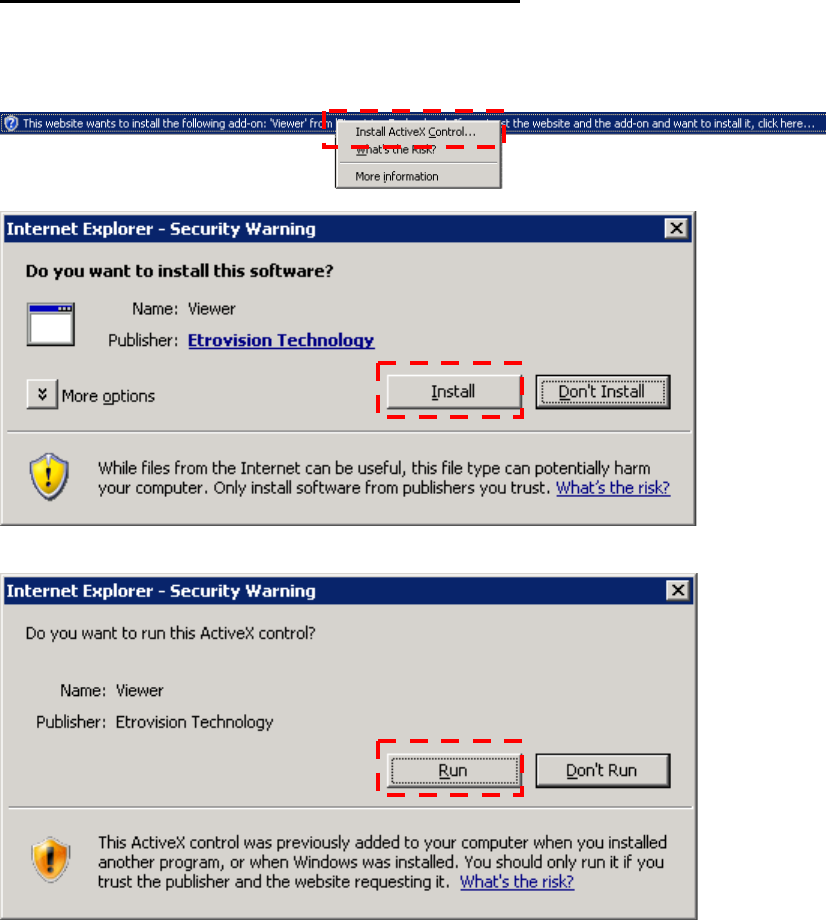
INSTALL AND RUN ACTIVEX CONTROL
After
suc
c
e
ssfu
l
log
in
,
the
following
pages
will
appear
at
first
time
.
Click
Install
button
to
install
ActiveX
Control
Click
Run
button
to
run
this
ActiveX
Control
17

INITIAL USERNAME & PASSWORD
Administrator
¤
Default
ID/Password
=
root/pass
.
¤
Only
password
is
changeable.
¤
Full
ac
cess
right
to
view
,
control
system
setting
s.
Guest
accounts
¤
ID/Passwo
r
d
not
ne
c
e
ssar
y
.
¤
Basic
view
and
some
action
buttons
can
wo
rk.
VIEWING AND OPERATTING PAGE
After
suc
c
e
ssfu
l
log
in
as
Guest
,
the
viewing
page
will
appear
a
s
follow
s.
The
“
camera
info
”
button
when
clicked
shows
FPS
,
came
r
a
name
and
reso
lution
valu
es.
Guest Mode Viewer
18
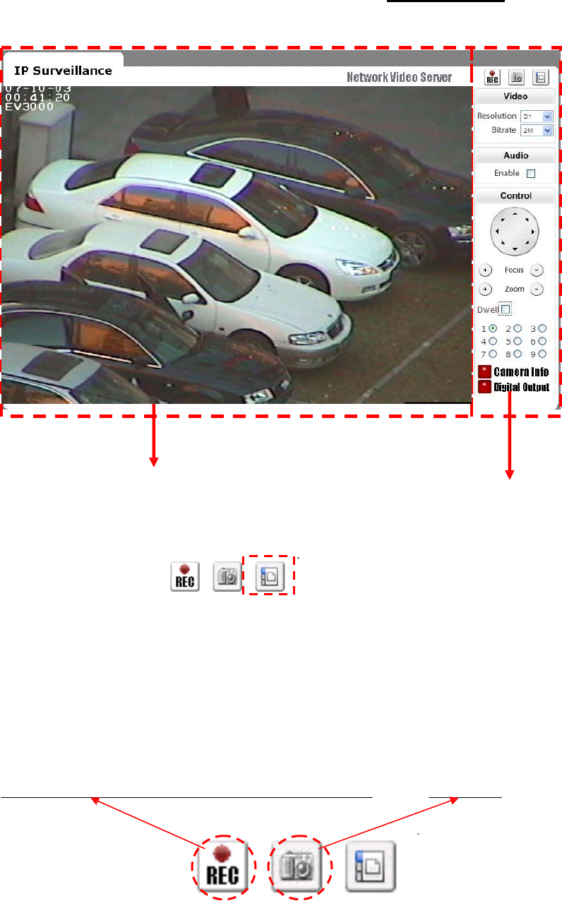
When
you
log
in
successfully
with
ROOT/PASS
as
administrator
,
the
viewer
screen
will
display
as
shown
below
.
Viewing Area Operating Area
1.
Notice
top
right
corn
e
r
o
f
viewing
page
has
a
toggle
button
to
take
you
between
web
configuration
page
&
viewing
page
.
Always
cli
c
k
that
if
you
want
to
move
fr
om
one
page
to
the
othe
r.
2.
Seve
r
al
controls
options
a
r
e
available
on
the
right
side.
3.
OSD
is
displayed
on
top
left
c
o
r
ne
r
o
f
the
scree
n
(time, date,
camera
name)
Live
recording
:
recor
d
live
stream
to
local
HDD
Snapshot
19
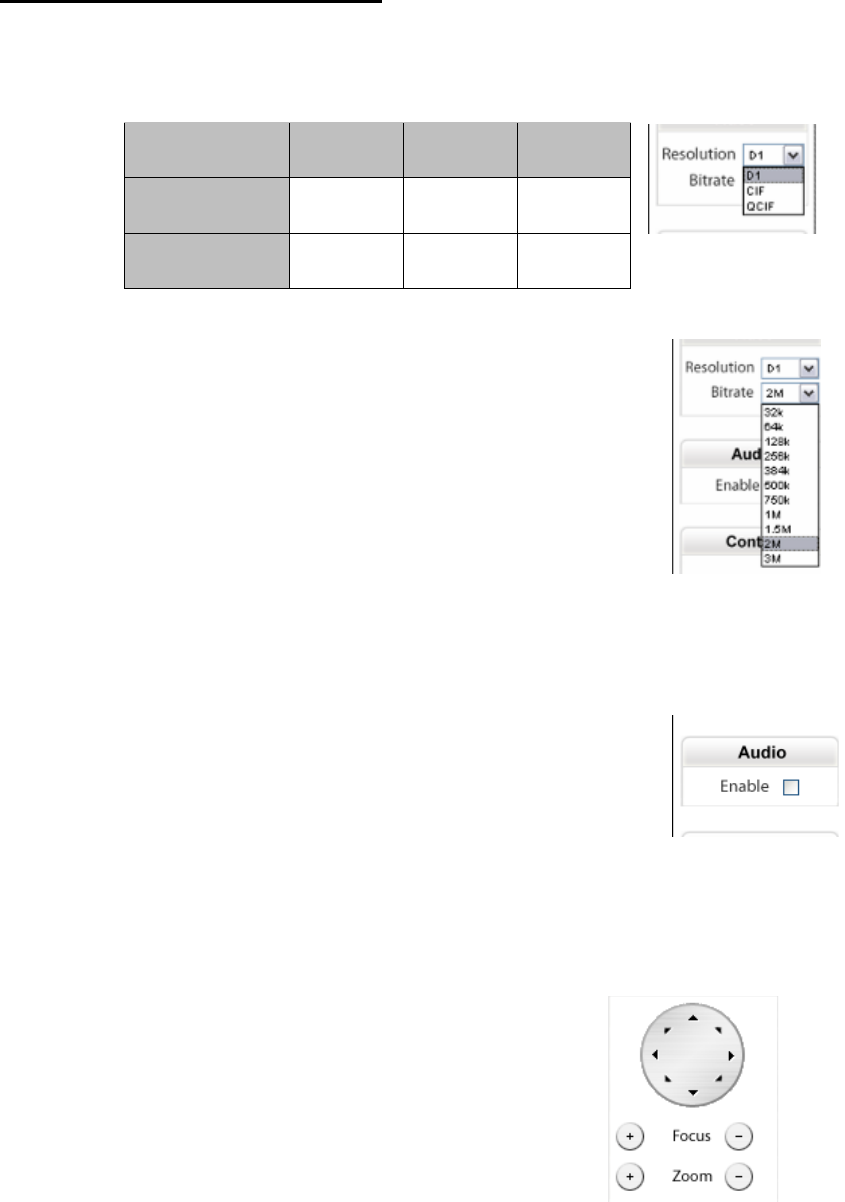
CONTROL PANEL SETTINGS
¤
Video/Resolution
Following
table
describes
resolution
values
for
each
video
format
Resolution CIF QCIF D1
NTSC 352X240 704X480 720X480
PAL 352X288 704X576 720X576
¤
Video
\
Bit
r
ate
s
f
Choose
a
particular
value
and
it
is
applied
within
few
second
s.
Video
on
the
screen
will
pau
s
e briefly
.
32K/64K/128K/256K/384K/500K/750K/1M/1
.5
M
/2M/3M
(bps)
¤
Audio
\
Enable
che
c
k
box
f
Enable
or
disable
func
tion
for
audio
will
r
esult
in
video
flicke
r for
a
second
and
then
return
back
to
normal.
This
is
not
an
error.
¤
P/T/Z
controls
(will
need
PTZ
controller)
f
Z
(Zoom):
zoom
in
(+)
/
zoom
out
(-).
f
Pan/Tilt.
f
F
(Fo
c
us):
focus
in
(+)
/
fo
cus
out
(-).
20
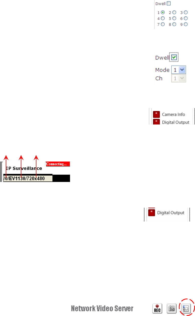
¤
Select
channel
number
in
fixed
channel
mode.
The
mode
is
fixed
channel
mode
,
if
Dwell
is
unchecked.
Channel
number
1
~
9
could
be
selected.
¤
Select
mode
number
in
auto-scan
mode.
The
mode
is
auto-scan
mode,
if
Dwell
is
checked.
Mode
number
1
~
9
could
be
selected.
¤
Camera
In
formation.
Shows
video
information
of
the
transferred
data
on
the
uppe
r
left
corner
o
f
the
video
screen
such
as
fr
ame
r
ate
(fps),
channel
name,
resolution.
FPS Name Resolution
¤
Digital
Output
f
When
enabled
,
DO
provide
contact
c
lo
s
e
and
acts
purely
as
a
switch.
8. WEB INTERFACE SETTINGS
Wireless
Video
Serv
er
built-in
web
interfa
c
e
offers
mo
re
advanced
settings.
On
the
main
viewing
page,
click
icon
located
on
top-right
side
to
enter
server
setting
s
page.
I
t
is
a
toggle
button
to
switch
between
Con
f
ig
and
viewer
page
s.
21
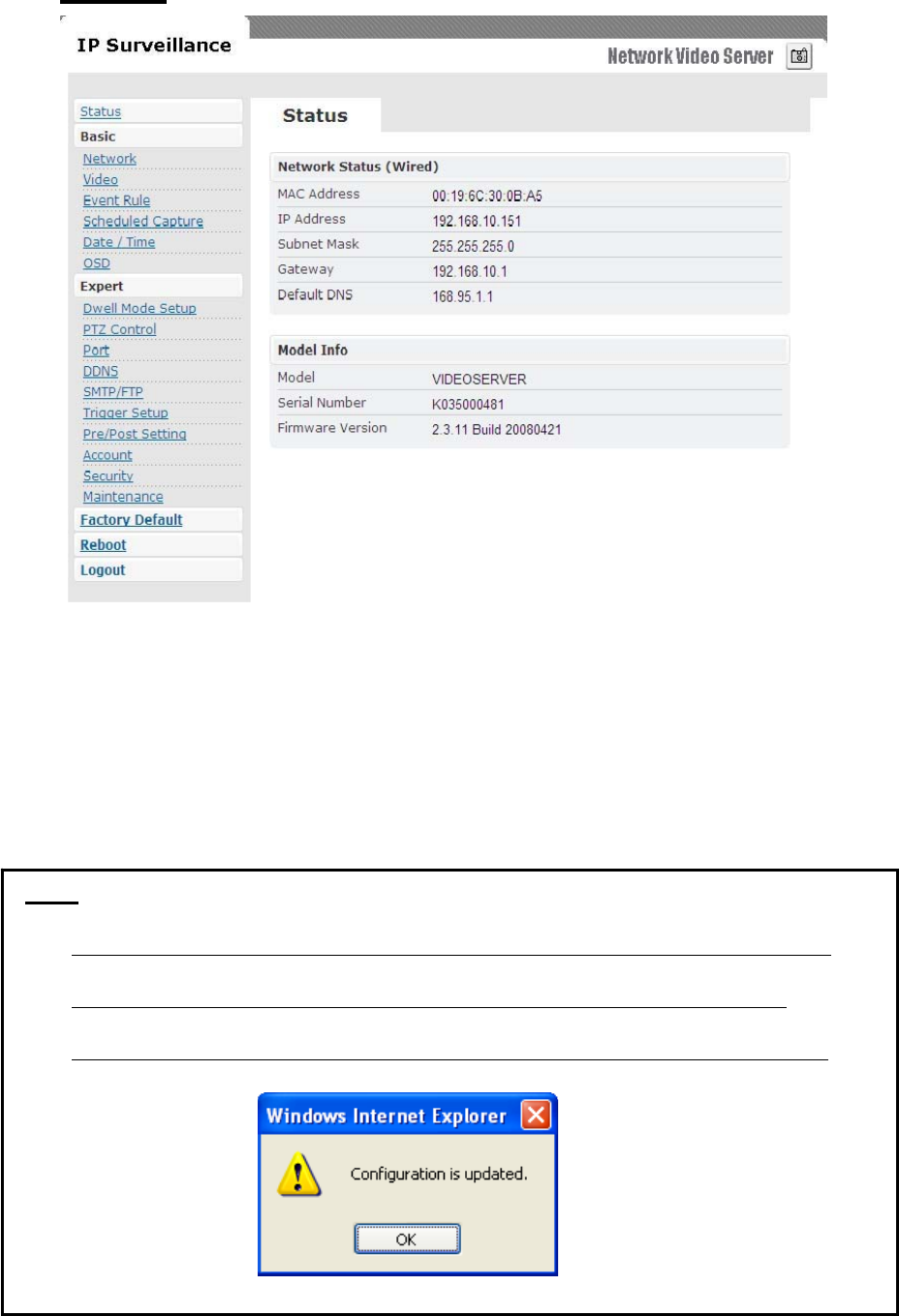
STATUS
¤
Initial
view
of
web
Config
interfa
c
e
is
statu
s
page.
¤
Hardwa
re
&
Firmwa
r
e
information
along
with
netwo
r
k
status
such
as
current
I
P
and
re
lated
details
a
r
e
clearly
shown.
¤
on
CCD
IP
CAMERAW
and
CMOS
IP
CAMERAW
model
22
NOTE
Remember to press “OK” after you have changed settings in a particular settings page
which has “OK” button. After few seconds, you can see a confirmation dialog box
informing that settings have been updated. Pressing OK will return to the same page.
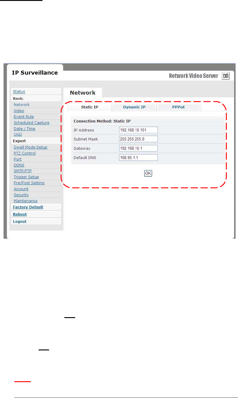
NETWORK
Three
configuration
types
are
available
for
wired
network
connection
STATIC,
DYNAMIC
&
PPPoE.
STATIC IP
¤
IP
Addre
ss
f
Confirm
with
netwo
r
k
administrato
r.
¤
Subnet
Mask/Gateway/De
f
ault
DNS
f
Confirm
with
netwo
r
k
administrato
r.
¤
Always
click
“
OK
”
to
save
changes
in
a
particul
ar
page.
¤
Reboot
is
required
and
will
be
automatically
triggered
after
you
p
ress “
OK
”.
Wait
for c
ount
down
timer
to
f
inish
and
page
will
r
e
fr
esh automatically
and
you
should
see
initial
login
page.
Note:
Always use IPScan to find the MAC address after reboot and double check the IP
23
address is correct. If IP was changed in web configuration, you cannot return to
initial login page after reboot.
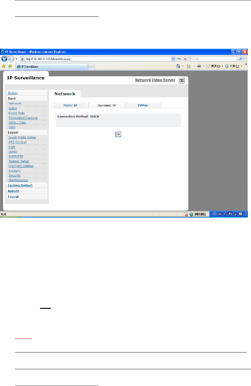
DYNAMIC IP
¤
If
DHCP
server
is
on
LAN
and
you
want
to
allocate
Dynamic
I
P
addre
ss,
u
s
e
DHCP
.
¤
Click
“
OK
”
button.
¤
Reboot
is
required
and
will
be
automatically
triggered
after
you
p
ress “
OK
”.
Wait
for c
ount
down
timer
to
f
inish
and
page
will
r
e
fr
esh automatically
and
you
should
see
initial
login
page.
Note:
Always use IPScan to find the MAC address after reboot and double check the IP
address is correct. If IP was changed in web configuration, you cannot return to
initial login page after reboot.
24
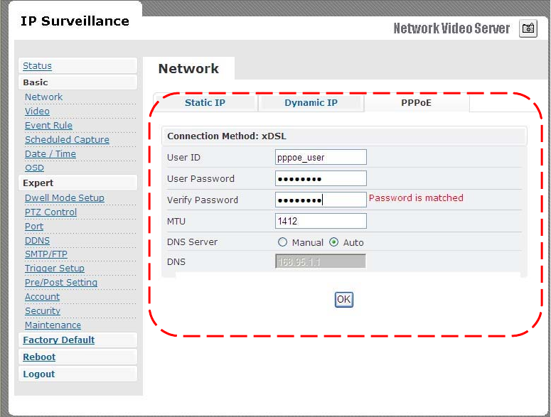
PPPoE SETTINGS
¤
PPPoE
i
s
u
s
ed
in
cas
e
netwo
r
k
support
s
PPPoE
like
xDSL
¤
Request
In
ternet
Service
Provid
er for
PPPoE
ID/Pa
s
sword
¤
User
ID
/
Passwo
r
d
f
PPPoE
us
er
ID
/
Pa
ss
word
¤
Service
Name
f
Service
name
o
f I
SP
¤
MTU
f
Maximum
transmission
unit
of
data
¤
IP
addre
ss of
DNS
seve
r
can
be
set
to
be
created
automatically
.
¤
If
xDSL
does
not
u
s
e
static
I
P
,
you
should
use
DHCP
.
25
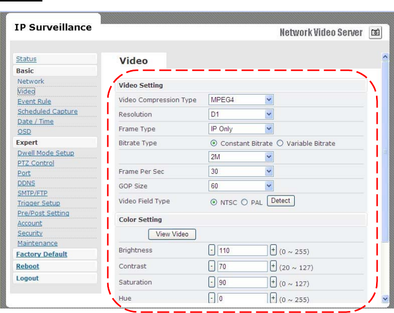
VIDEO
VIDEO SETTINGS
¤
Video
Compression
Type
f
MJEPG
/
MPEG4
¤
Re
s
olution
f
QCIF
/
CIF
/
D1
¤
Fr
ame
Type
s
This
setting
deals
with
the
Group
o
f
Pictures
(GOP)
structure
-
which
could
be
a
combination
of I
and
P
fr
ames.
I
-
I fr
ames
-
also
re
ferred
to
a
s
Key
fr
ames
contain
information
for
a
complete
picture
,
and
can
be
decoded
independent
o
f
any
othe
r fr
ame.
I fr
ames
are
the
largest
(and
least
compressed)
fr
ame
s.
Th
erefor
e
for
same
quality
,
they
consume
high
bit
r
ate.
26

27
P
-
P
fr
ame
s
a
r
e
encoded
u
s
ing
information
from
the
p
r
evious
I
o
r
P
fr
ame
,
and
c
an
only
be
de
c
oded
c
o
rr
e
c
tly
i
f
the
p
r
evious
I
/
P
fr
ame
is
available.
P
fr
ames
are
smaller
than
I fr
am
es.
f
I
Only
/
I
P
Only
f
IP
-
Simple
Profile
-
Medium
bit
r
ate
s for
same
quality
.
I
-
Highest
bit
r
ate
s for
same
quality
.
**When
choosing
M
J
EPG
streaming,
ONLY
support
“I
Only
”
mode
¤
Bit
r
ate
Type
f
Constant
and
Va
r
iable
bit
r
ate
s
control
allows
flexibility
in
choosing
how
much
bandwidth
i
s
available
on
network
and
quality
of
video
re
quired.
¤
Constant
Bit
r
ates
f
3M
/
2M
/
1.5M
/
1M
/
750K
/
500K
/
384K
/
256K
/
128K
/
64K
/
32K
¤
Variable
Bit
r
ate
s
f
2
~
31
(quality
i
s
best
in
case
value
i
s “
3
”)
¤
Fr
ame
per
Second
.
f
1
~
30
¤
Group
Size
f
Adjusts
the
r
ation
between
“I” fr
ames
and
“P”
fr
ame
s.
Lower
the
group
size
,
bette
r
the
quality
.
f
5
/
10/
15
/
30
/
60
¤
Video
Type
f
NTSC
/
PAL
**System can automatically detect input video signal when clicking “detect” icon
COLOR SETTINGS
Fine
adjustments
to
video
quality
can
be
made
using
more
detailed
settings
as
shown
below
.
BRIGHTNESS
Adjust
s
the
image
on
a
scale
fr
om
darkne
ss
to
bright
ness.
CONTRAST
Adjust
s
the
extent
to
which
adjacent
area
s
on
a
video
diffe
r
in
brightness
SATURAT
I
ON
Adjust
s
the
chr
omati
c
purity
o
f
video
the
r
eby
e
ffe
cting
vividne
ss.
HUE
Adjusts
the
video
by
effe
cting
color
depth
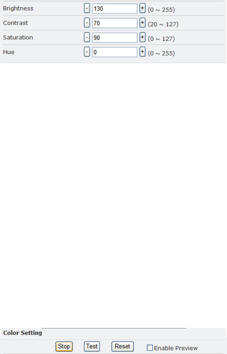
VIDEO PREVIEW
Preview
make
s
choi
c
e
s
easier
when
tuning
video
s
etting
s for
specifi
c
location
s.
By
cli
c
king
the
View
Video
butt
on,
you
can
see
the
following
28

29
Click
Stop
to
exit
p
r
eview
.
You
could
change
other
video
pa
r
ameters
and
pre
ss
TEST
to
see
how
the
change
s
look
like
.
You
can
pre
ss
Reset
anytime
to
return
back
to
the
default
settings.
Click
Enable
Preview
checkbox
to
save
the
curr
ent
setting
s
–
and
it
s
take
s effec
t
right
af
te
r
settings
have
been
changed.
MAX CLIENT LIMIT
Maximum
users
(
c
lient)
limit
allows
u
sers
accessing
the
video
stream
.
Fo
r
higher
bit
r
ate
s
and
reso
lution,
the
client
limit
i
s
much
lower
and
vice
ve
rsa.
¤
Maximum
number
of
clients
can
be
re
stricted
depending
on
how
much
video
quality
is
required
and
netwo
r
k
band
with
is
available.
f
0
~
10
(value
0
mean
s
maximum
allowable)
DO
NOT
FORGET
TO
PRESS
“OK”
BUTTON
TO
SAVE
YOUR SETTINGS.
EVENT RULE
1.
Digit
Input
2.
Motion
Detection
3.
Periodic
Timer
4.
Network
Lo
ss
5.
Video
Lo
ss
6.
Powe
r
Lo
ss
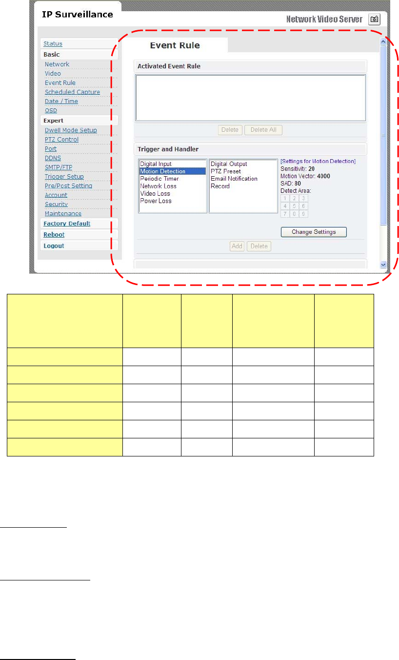
Digital
Output
PTZ
Preset
Email
Notification
Record
to
FTP
Server
Digital
Input
X
X
X
X
Motion
Detection
X
X
X
X
Periodic
Timer
X
X
X
Network
Loss
X
X
Video
Loss
X
X
Power
Loss
X
EVENTS HANDLED
Digital
In
put
Can
choose
sen
sor
type
eithe
r
“Normal
Open”
o
r
“Normal
Clo
se”
Motion
Detection
If
motion
is
detected
on
the
are
a
s
defined
on
the
video
stream
,
an
event
will
be
triggered
based
on
the
r
ule
list
s.
Periodic
Timer
30

31
In
a
p
r
e-defined
time
interval,
an
event
will
be
triggered
based
on
the
ru
le
list
s.
Network
Lo
ss
When
system
detect
network
lo
ss,
an
event
will
be
triggered
Video
Lo
ss
When
system
detect
video
lo
ss,
an
event
will
be
triggered
Powe
r
Lo
ss
When
system
detect
power
loss,
an
event
will
be
triggered
ACTIONS TRIGGERED
Digital
Output
Can
active
digital
output
.
PTZ
Preset
PTZ
set
to
a
particula
r
preset
value
can
be
triggered
based
on
occurrenc
e
of
an
event
listed
out
in
“
Rule
Lists
”.
E-mail
Notification
E-mail
can
be
sent
based
on
o
ccurre
n
c
e
o
f
an
event
listed
out
in
“
Rule
Lists
”.
Record
to
FTP
ser
v
er
When
event
triggered
,
system
will
record
streaming
to
FTP
ser
ve
r.
RULE LISTS - ADDING/DELETING
Select
an
event
and
select
corr
esponding
action.
Cli
c
k
add
button
and
notice
that
is
added
in
the
Rule
lists
Information
bo
x.
MODIFYING RULE LISTS
Rule
list
item
s
can
be
deleted
individually
or
wholly
by
clicking
Delete
All
button.
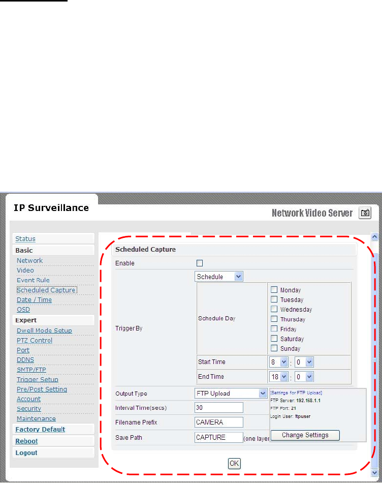
CAPTURE
Choose
Enable
che
c
kbox
to
recor
d
snapshot
by
schedule
or
event triggered
way
.
Schedule
capture
-
Select
schedule
day
check
boxe
s
(
c
an
multi-select)
-
Define
start
and
end
time
-
Choose
output
type
a
s “F
TP
upload”
-
Define
r
elated
output
paramete
r,
such
as
interval
time,
save
path
…
32
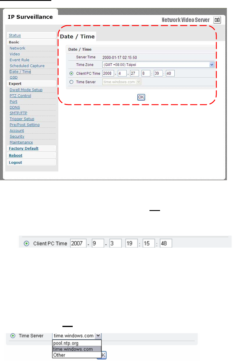
DATE & TIME
¤
Date
and
time
settings
can
be
syn
c
hronized
with
PC
directly
by
cli
c
king
“Client
PC
time
”
check
bo
x.
Click
“
OK
”
after
you
have
made
selectio
n.
¤
Time
zone
can
be
cho
s
en
by
choosing
eithe
r
o
f
the
two
time
s
e
r
v
ers
listed
¤
Either
of
the
two
time
se
rvers
can
be
cho
s
en
to
synchronize
video
server
time
.
They
are
listed
a
s
follows
should
you
choose
Time
Server.
Click
“
OK
” af
ter
you
have
changed
setting
s.
¤
If
you
want
to
manually
input
time
serv
e
r,
choose
“
Other
”
then
you
can
find
a
manual
input
edit
box
appea
r.
Key
in
you
r
preferred
time
33
ser
v
er
and
click
“
OK
”.
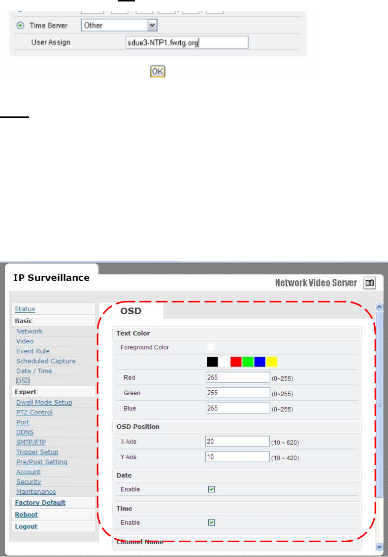
OSD
Click
on
yo
ur
desired
choice
of
colo
r.
Value
s
will
change
a
c
cordingly
for
R,
G,
and
B
. If
you
desire
some
other
colo
r,
you
can
manually
define
those
corre
sponding
R,
G,
B
values
in
the
boxe
s
as
appropriate.
Position
of
OSD
can
be
changed
by
defining
the
X,
Y
values.
Date
&
Time
can
be individually
enabled/disable
by
“Date”
&
“
Time”
che
c
kbox
es.
Channel
name
can
be
shown/hidden
by
the
channel
name
“
Enable
”
checkbox
.
It
can
be
manually
typed
in
the
“
Channel
name
”
text
box
and
change
s
can
be
noticed.
34
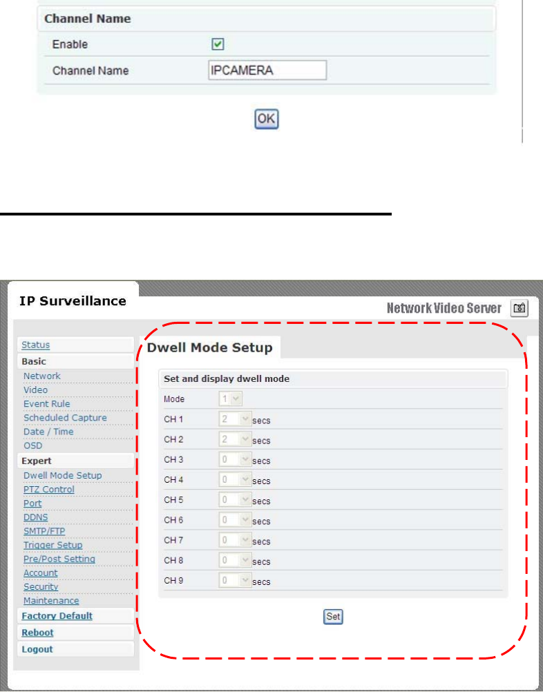
DWELL MODE SETUP (ATUO-SCAN MODE)
The
setting
values
of
mode
of
auto-scan
mode
can
be
changed
by
“
Set
”
button.
Mode
1
to
9
could
be
support
in
auto-s
can.
And,
dwell
time
1
to
120
seconds
of
each
channel
c
ould
be
set.
The
channel
number
is
re
moved
from
auto-scan
model
,
if
dwell
time
i
s
set
to
0
se
c.
35
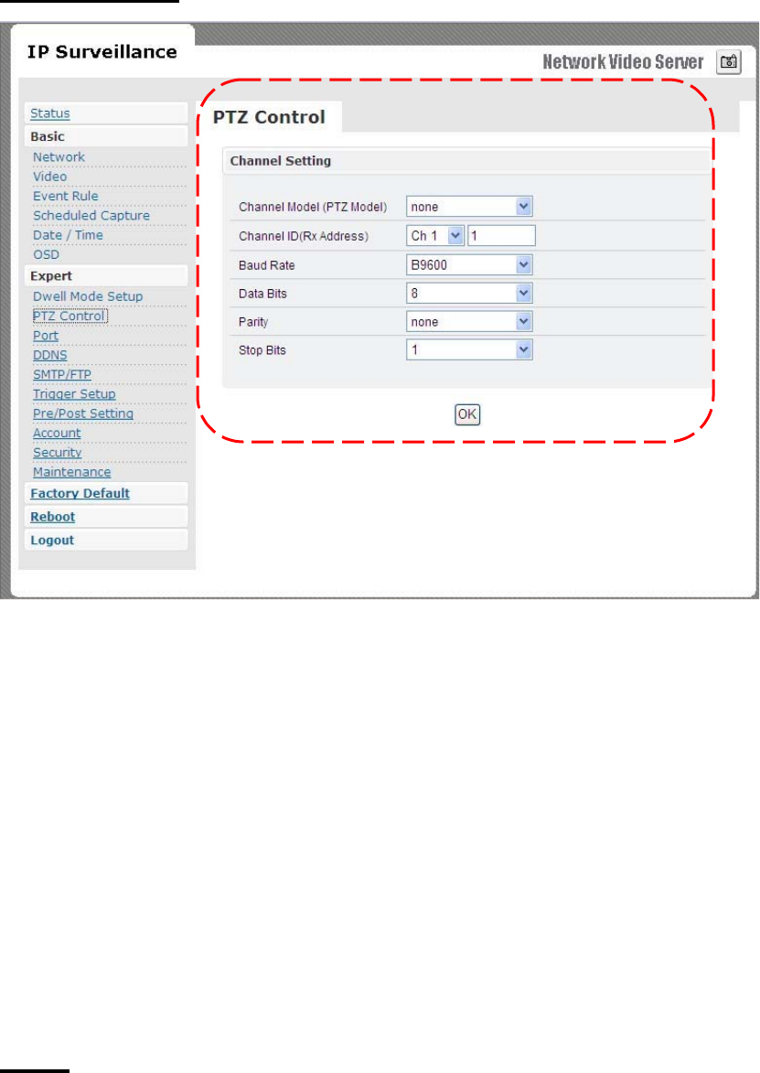
PTZ CONTROL
¤
Channel
Mode
(PTZ
model)
f
Default
is
none.
f
PelcoP/
PelcoD/
T
r
ansparent
can
be
cho
s
en
.
¤
Channel
ID
f
Give
addre
ss
value
for
channel
1
to
9.
¤
Baud
r
ate
/
Data
bits
/
Parity
/
Stop
bit
s
f
Depending
on
the
p
r
otocol
u
s
ed,
the
values
o
f
baud
and
related
settings
are
to
be
assigned
accordingly
.
PORT
The
value
s of
WEB
and
AV
port
can
be
changed
a
s
ne
cessar
y
.
36
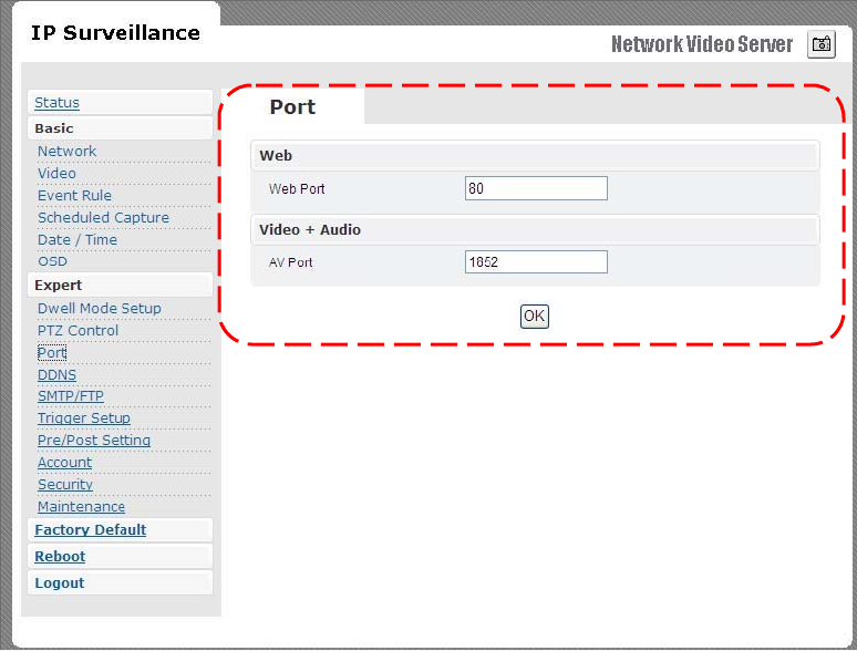
Web
¤
Web
Port
default
is
80
Video + Audio
¤
Default
i
s
1852
for
video/audio
data
tran
s
mission.
37
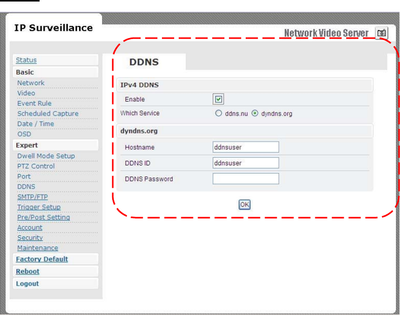
DDNS
DDNS
is
the
function
that
maps
an
IP
addre
ss
to
a
host
name.
If
Wireless
Video
Serv
er are
set
to
dynamic
IP
address,
the
host
name
by
DDNS
(Dynamic
Domain
Name
Service)
must
be
u
s
ed
instead
of
the
I
P
addre
ss for cr
edibility
o
f
netwo
r
k
connectio
n.
IPv4 DDNS
¤
Check
“
Enable
”
and
select
a
service
out
o
f
available
two
.
¤
Both
services
are re
quired
to
register
some
item
s
on
each
DDNS
serv
ice
s
ite
.
¤
Fo
r
u
s
e
o
f “
ddns.nu
” re
gister
at
www.ddns.nu
and
for
dyndns
find
the
information
at
dyndns.org
38
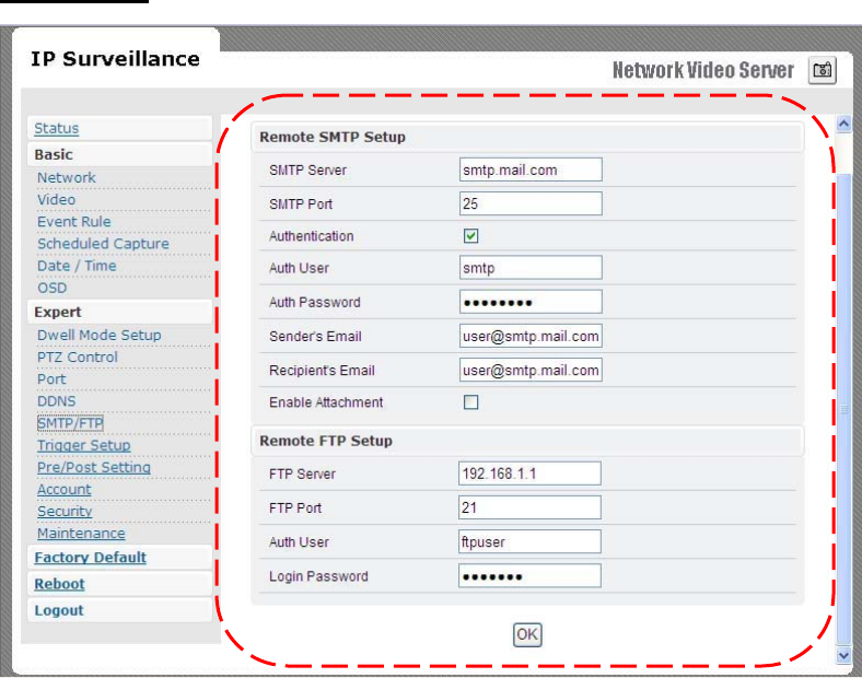
SMTP/FTP
An
e-mail
notification
&
FTP
upload
service
offere
d
by
Wirele
ss
Video
Serv
er
notifies
event
s or
upload
s
snapshot
s
to
a
remote
FTP
se
rv
e
r.
E-MAIL – SMTP SETTINGS
Fill
in
the
details
of
SMTP
server
such
a
s
port
numbe
r,
use
r
name,
password,
ser
v
er
name
information.
If
you
would
wish
to
send
attached
snapshots,
please
check
the
appropriate
check
bo
x.
Sometime
s
Authentication
is
not
always
required
by
SMTP
servers.
Wherein
only
the
SMTP
server
name
and
e-mail
add
ress
details
are
enough
to
be
input.
39
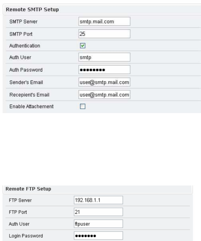
FTP SETTINGS
Fill
in
the
details
of
remote
FTP
serv
e
r,
port
numbe
r
and
user
name,
password.
40
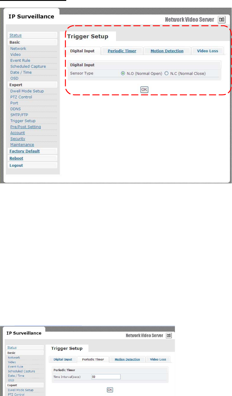
TRIGGER SETUP
Three
di
ffer
ent
type
s of
EVENTS
can
be
configured
.
Digital INPUT
Can
be
Normal
OPEN
(N.O)
or
Normal
Close
(N.C)
Choose
based
on
the
type
o
f
input
and
press
OK
to
save
the
setting
s.
PERIODIC TIMER
Timer
inte
r
val
can
be
set
in
term
s of
second
s.
Thi
s
will
trigger
an
event
when
the
time
out
is
achieved.
41
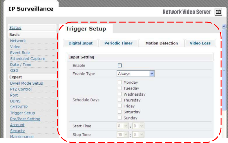
MOTION DETECTION
¤
Enable
type
f
Can
enable
motion
detection
by
“alway
s” or “
schedul
e”
mode
f
When
choosing
schedule
mode,
define
schedule
day
and start/end
time
¤
Detection
Area
f
Total
viewing
screen
area
is
divided
into
9
square
blocks
and
each
of
them
is
called
area
1,
area
2
etc.
,
Click
spe
c
ific
areas
you
want
motion
detection
to
be
enabled.
If
a
dete
c
tion
area
is
selected
c
olor
change
s
to
da
rk
gray
.
42
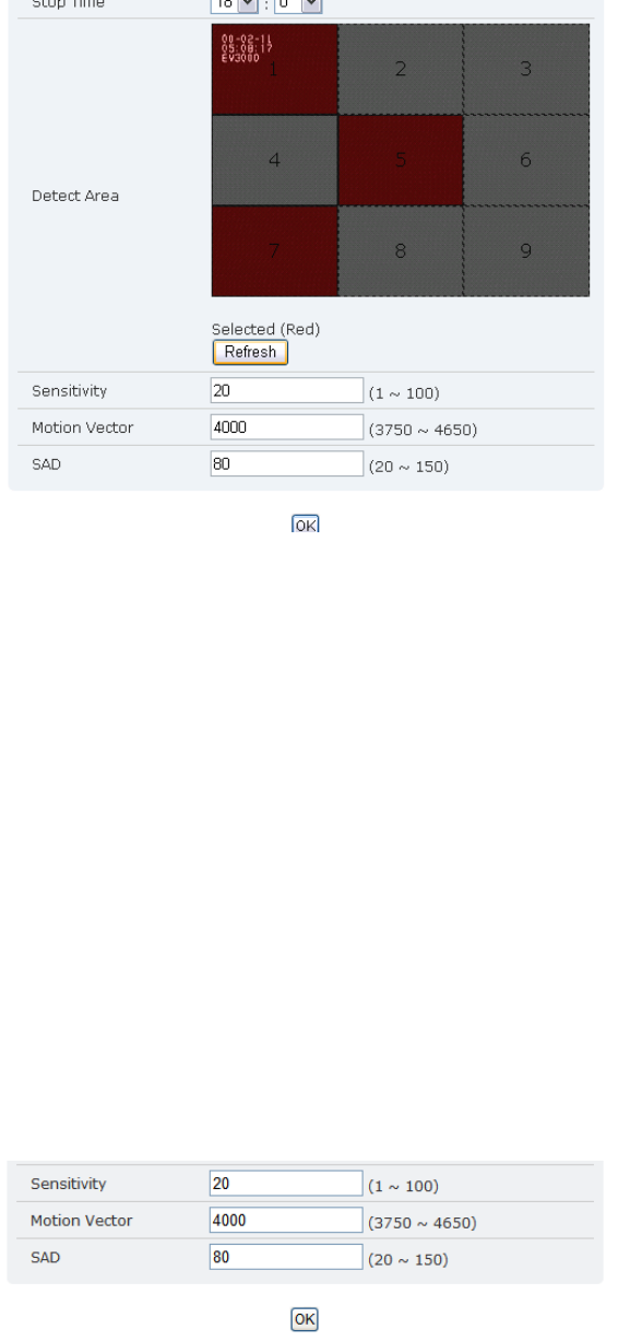
¤
Sensitivity
value
f
Define
s
sensitivity
of
the
motion
dete
c
tion
.
The
r
ange
o
f
the
value
i
s
1
to
1
00.
¤
Motion
Vector
value
f
To
detect
even
slighte
s
t
movement
for
objects
in
selected
area
,
please
select
a
lowe
r
motion
vector
value.
The
r
ange
of
the
value
is
3750
to
46
50.
¤
SAD
value
.
f
To
only
detect
f
lashing
light
o
r
any
s
u
c
h
s
igni
f
icant
activities
on
immovable
objects,
low
SAD
value
should
be
ch
osen. In
most
case
s,
high
SAD
level
is
re
commended.
The
r
ange
o
f
the
value
is
20
to
150
.
Motion
detection
enabled
area
s
look
a
s
shown
below
.
A
simple
click
can
select
any
of
the
boxe
s
on
detect
a
rea.
43
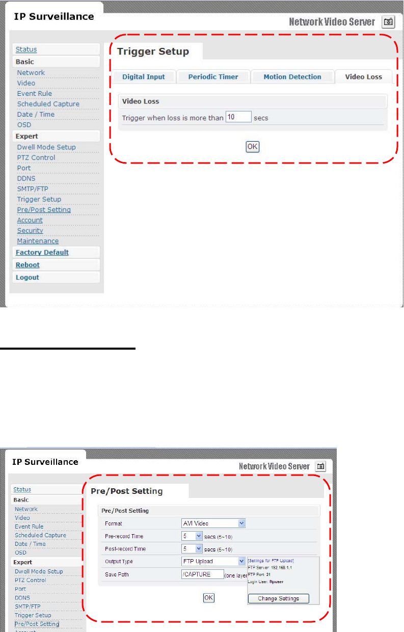
Video Loss
Can
config
how
much
time
system
should
trigger
an
event
for
video
los
s
PRE/POST SETTING
These
parameters
decide
Pre/Post
buffer
stream
format
type
and
duration
.
Administrator
can
choose
format
a
s “
AVI
Video”
o
r
“JPEG
Pict
ure”
with
Pre/Post
time
duration
44
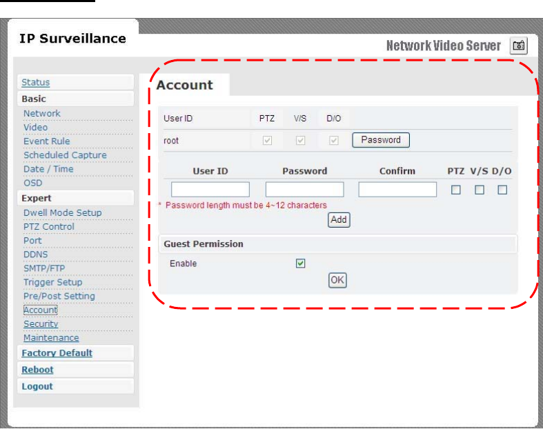
ACCOUNT
Administrator
can
cr
eate
u
ser
accounts.
Login
as
an
administ
r
ator
and
create
use
r
accounts
by
pressing
“
Add
”.
Each
a
cco
unt
has
PTZ,
Video
settings
and
Digital
Out
privileg
es.
They
can
be
turned
on
or
o
ff
anytime
by
the
administrato
r.
There
a
r
e
limits
on
u
ser
name
and
passwo
r
d
length
and
will
be
notified
by
dialog
boxe
s
if
the
u
ser
name/passwo
r
d
exceeds
or
under-run
s
that
limit.
Fo
r
each
account,
guest
permission
s
can
be
turned
ON/OFF
.
Any
time
,
an
account
’s
setting
s
can
be
modified
by
pre
s
sing
the
“
Modify
”
button.
45
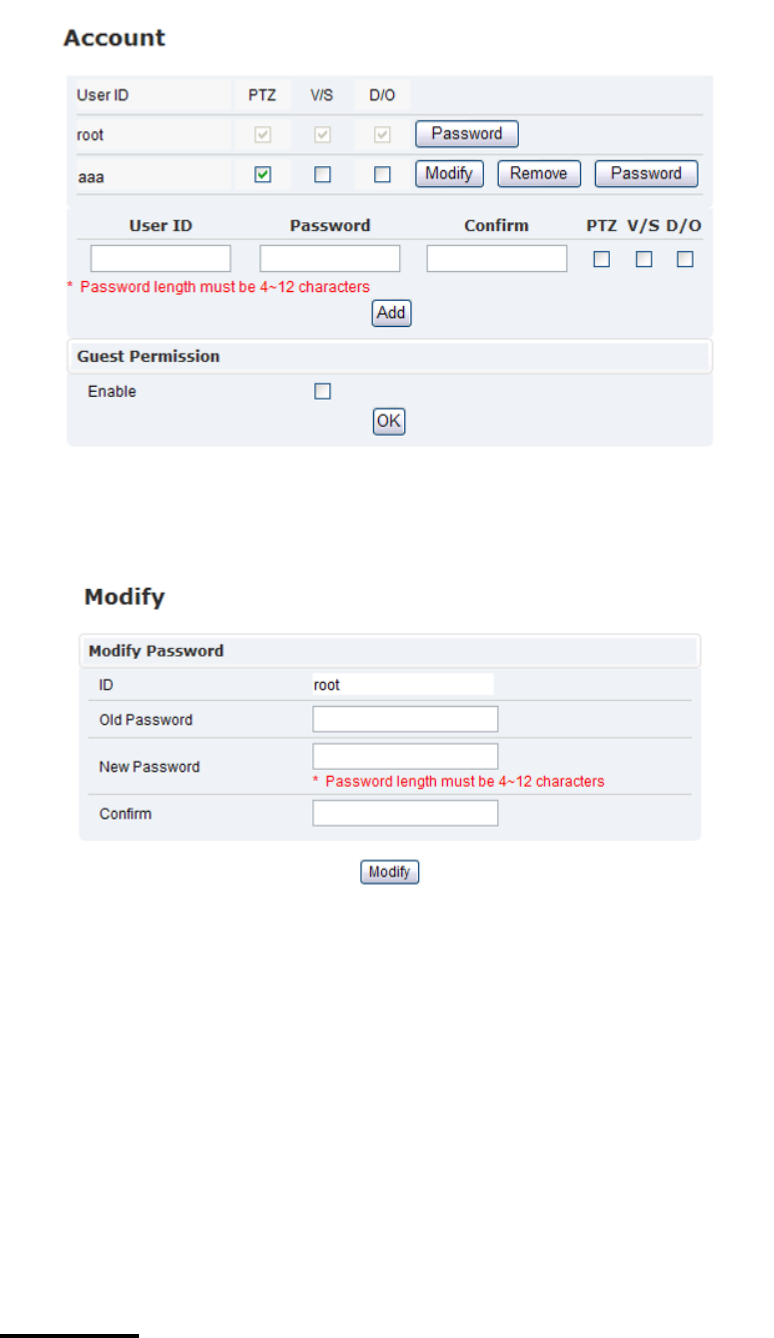
Administrator
account
password
can
also
be
modified
by
“Pa
s
sword
”
button.
Changing
password
needs
confirmation.
Account Limitations
¤
Administrator
can
add
up
to
a
maximum
of
5
us
ers
and
assign propertie
s for
each
of
them.
Guest Permissions
¤
Guest
account
can
be
turned
ON/OFF
anytime.
SECURITY
The
basic
setting
s are
LOW
by
default.
46
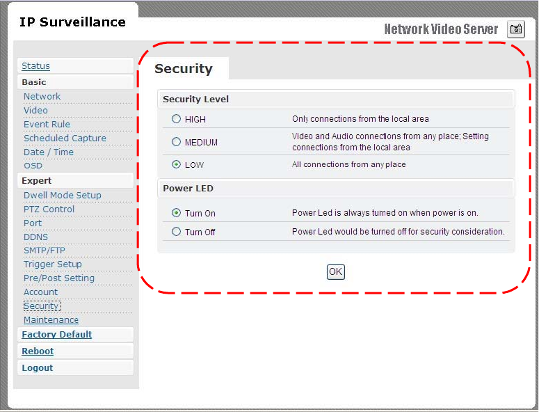
¤
Security
Level
f
HIGH
m
ONLY
LAN
connection
s are
allowed.
f
MEDIUM
m
Video
and
audio
connections
from
any
location
and settings
fr
om
LAN
are
permitted
.
f
LOW
m
All
connections
from
any
location
are
permitted.
¤
Powe
r
LED
f
Tu
r
n
On
m
Default
value,
powe
r
LED
will
always
be
on
during operation.
f
Tu
rn
O
ff
m
Config
power
LED
a
s
o
ff
during
operatio
n.
47
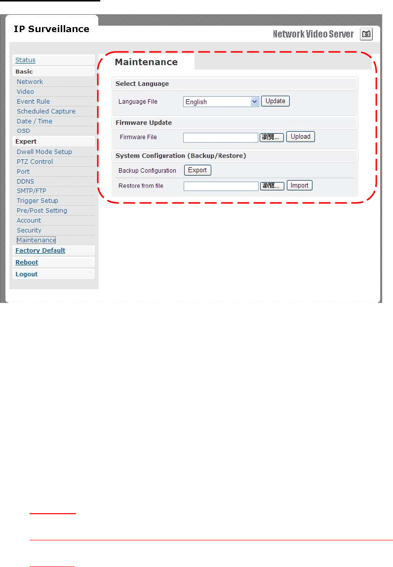
MAINTENANCE
Language
•
Default
setting
s are
in
Engli
sh.
A
choice
of
T
r
aditional
Chinese
i
s
available.
Firmware update
•
Firmwa
re
update
bina
ry
file
can
be
obtained
yo
ur
reselle
r.
Choose
that
and
click
upload
.
When
uploading
is
do
ne,
reboot
is
required
and
will
be
automatically
triggered.
CAUTION
DO NOT power off during upgrade process, follow system dialog to finish upgrade
procedure
System Configuration (Backup/Restore)
•
You
can
backup
curr
ent
con
f
ig
ur
ation
profile
as
a
file
and
restore
any
sto
r
ed
con
f
iguration
profile.
48

9. FACTORY DEFAULT
After
a
con
f
irmation
dialog
bo
x,
clicking
OK
butt
on,
will
load
de
f
ault
settings
and
do
a
reboot.
You
will
see
the
re
boot
countdown
timer
running.
Once
done,
you
will
see
the
login
page
.
Please
login
with
r
oot/pa
ss.
10. REBOOT
If
you
click
OK
on
the
dialog
box,
you
will
see
the
r
eboot
countdown
time
r
running.
Once
done
,
you
will
see
the
login
page.
Please
login
with
root/pass
or
othe
r
appropriate
login
information.
11. LOGOUT
To
return
to
the
login
scre
e
n,
simply
cli
c
k
lo
gou
t.
You
should
see
yourself
in
the
login
page
within
seconds.
49

12. USB Config Port - FIRST TIME EXPERIENCE
If
Wireless
Video
Serv
er
ha
s
to
be
quickly
c
o
nf
ig
ur
ed
o
r
has
to
be
set
to
fact
ory
de
f
ault
setting
s,
USB
config
port
is
used
to
a
c
hieve
that
.
USB
config
port
is
a
special
USB
port.
Insert
mini
USB
cable
onto
USB
con
f
ig
port
and
connect
other
end
to
PC.
When
video
se
rver
is
powered
on,
such
port
will
not
be
operational.
Once
you
are
done
working
with
USB
config
port,
remembe
r
to
unplug
USB
cable
from
USB
conf
ig
port
.
NOTE
REMOVE USB CABLE WHEN YOU ARE FINISHED WITH QUICK CONFIGURATION.
SUPPORTED OS
PC
running
the
following
operating
systems
can
support
auto
ru
n
of
Qu
i
ck
Config
application.
1.
Window
s
Vista
-
auto
run.
2.
Window
s
XP
-
auto
run.
NO SOFTWARE INSTALLATION REQUIRED
There
i
s
no
installation
or s
etup
of
any
sof
twa
re for
Window
s
Vista/XP
platform
s.
50
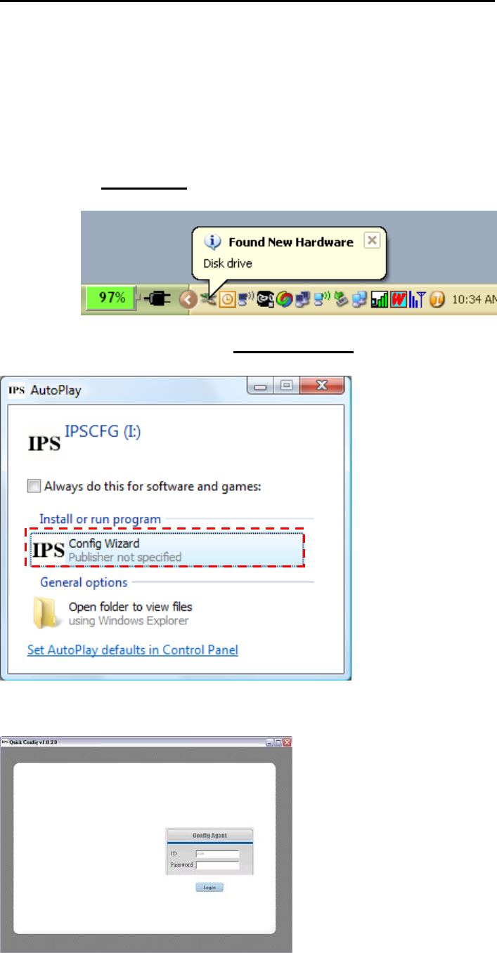
STEPS FOR USING USB config port (Windows XP PC)
1.
Disconnect
power
cable
connected
to
Wireless
Video
Serve
r.
2.
Use
mini-USB
cable
and
connect
appropriate
end
to
USB
con
f
ig
port
and
connect
other
end
to
PC
USB
port.
3.
After
5
~
10
second
s
depending
on
how
fa
st
yo
ur
PC
is,
you
can
notice
“
Disk
drive
”
being
dete
c
ted.
4.
A
POP-UP
dialog
show
s “
Config
Wizard
”
is
ready
to
run.
Pre
ss
OK.
Double
click
Con
f
ig
Wizard.
You
will
see
a
screen
as
fo
llows.
51
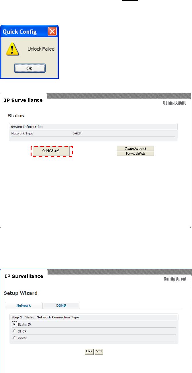
You
will
be
asked
for
password
.
Earlie
r,
if
you
have
neve
r
changed
the
password
for
use
r
root
,
please
type
pass
as
the
passwo
r
d.
Then
click
login
button.
If
you
input
wrong
passwo
r
d,
you
will
get
this
dialog
bo
x.
You
will
see
the
netw
ork
status
of
Wireless
Video
Serv
er .
To
navigate
through
Quick
Wizard,
click
it
and
you
will
find
a
window
appear
as
below
.
52
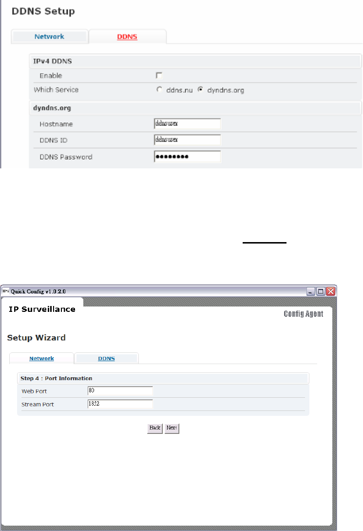
If
you
would
wish
to
change
network
settings
o
f
eith
er
STATIC
/
DHCP
/
PPPoE
If
you
would
want
to
setup
DDNS
,
please
click
on
the
same
for
detailed
configuration.
Return
to
Network
page
to
setup
netwo
r
k
fu
rthe
r.
Please
choose
and
cli
c
k
nex
t for
detailed
configuration
page.
Fo
r
instan
ce, s
hown
below
is
a
scre
en
whi
c
h
ha
s
STATIC
network
configuration
page.
Click
next
to
pro
c
eed.
53
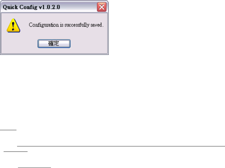
Please
input
web
port
and
stream
port
if
default
value
doe
s
not
match
yo
ur re
quirement
Cli
c
king
next
will
s
how
that
s
etting
s ar
e
saved.
You
c
an
cli
c
k
finish
if
you
are
done
o
r
go
back
or
change
other
settings.
Similarly
you
can
change
other
settings
at
ea
se.
Note:
f
Connect CCD IP CAMERA/CMOS IP CAMERA to your network by using a
standard
Cat-5 cable.
54