CipherLab 3656CRADLE Cradle User Manual
CipherLab Co., Ltd. Cradle Users Manual
UserManual.wiki
>
CipherLab
>
3656CRADLE User Manual
Users Manual
Navigation menu
Upload a User Manual
Namespaces
Wiki Guide
HTML
PDF
Info
Views
User Manual
Discussion / Help
Navigation
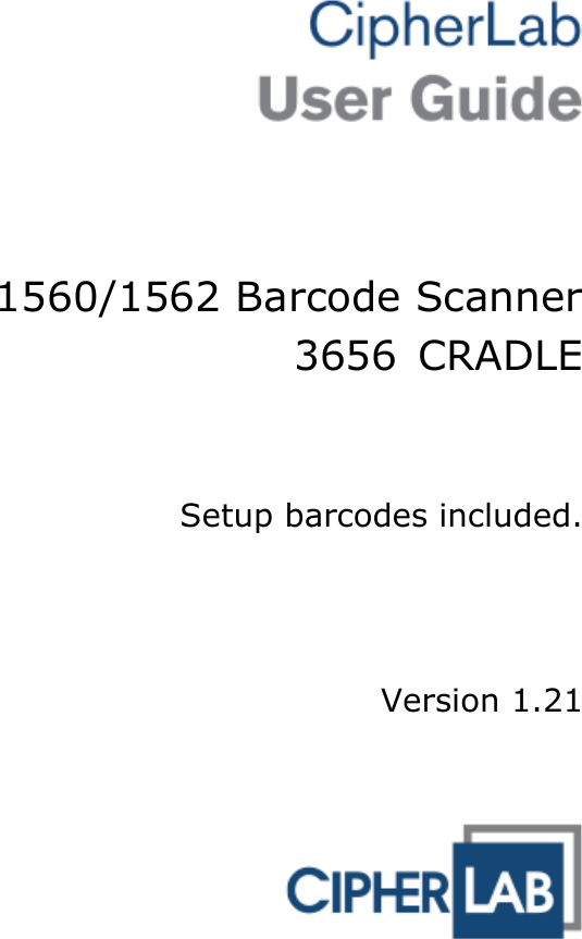


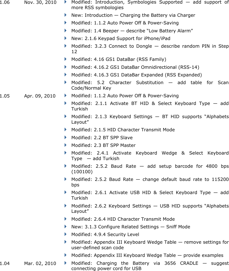
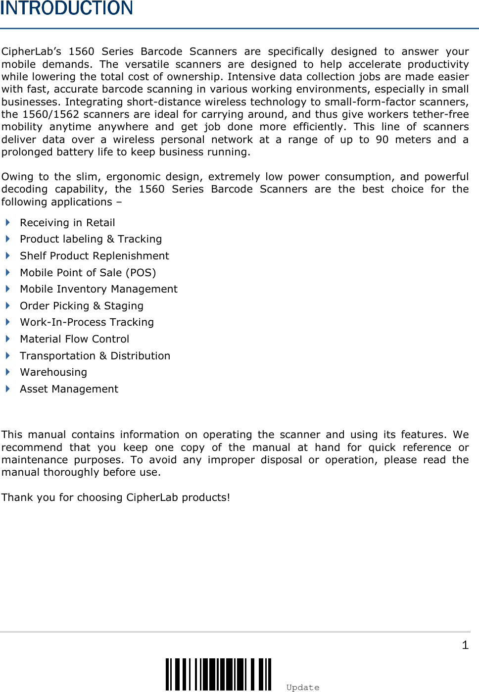
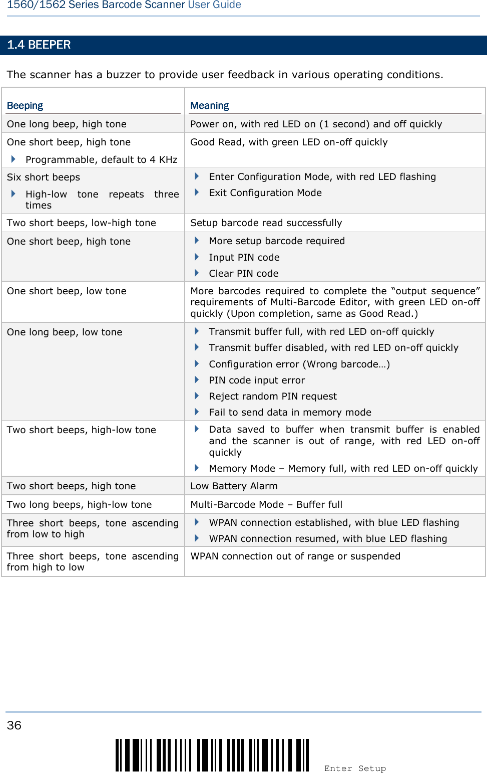
![3 Update ! ! ! ! [[[[] ] ] ] Heading 1 Heading 1 Heading 1 Heading 1 SETTING UP SETTING UP SETTING UP SETTING UP 3656365636563656 CRADLECRADLECRADLECRADLE Capable of charging 1560/1562, the 3656 CRADLE stand is specifically designed for the scanner to communicate with a host computer wirelessly. The connection between the scanners and 3656 CRADLE is made easy and reliable. Refer to 3.1.1 Connect to . The 3656 CRADLE stand is also an Auto-Sense stand when used with the scanner set to Auto-Sense mode. Two LED indicators are provided for power and communications status. Power LEDPower LEDPower LEDPower LED MeaningMeaningMeaningMeaning Red, solid --- Power ON --- --- Power OFF Communication LEDCommunication LEDCommunication LEDCommunication LED MeaningMeaningMeaningMeaning --- Blue, solid Initialize Red, solid --- Failed to establish a USB connection Red, solid Blue, flashing Serial command mode with USB Virtual COM or RS-232: wait 3 seconds for starting a serial command Red, flashing Blue, flashing Serial command mode with USB HID: wait 3 seconds for pressing [Num Lock] or [Caps Lock] 5 times via keyboard --- Blue, Wait for connection request from the scanner (Slow flash at 0.5 Hz)](https://usermanual.wiki/CipherLab/3656CRADLE/User-Guide-3879656-Page-21.png)
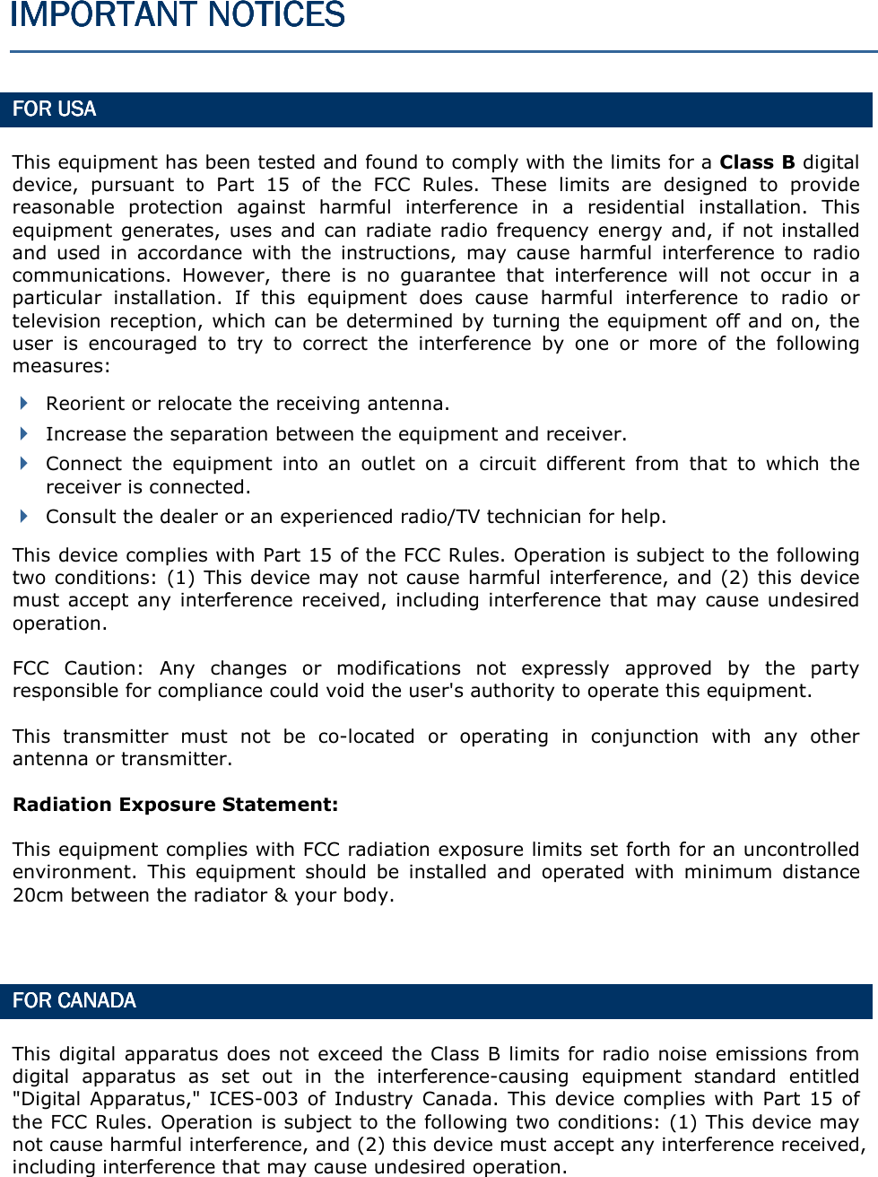
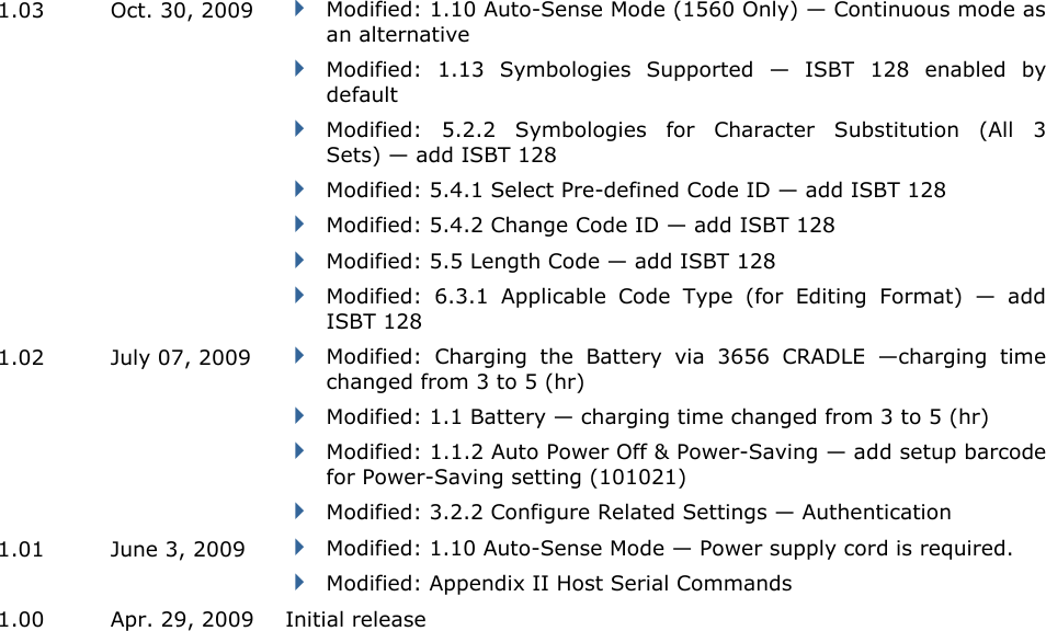
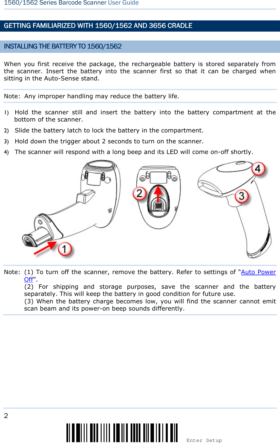
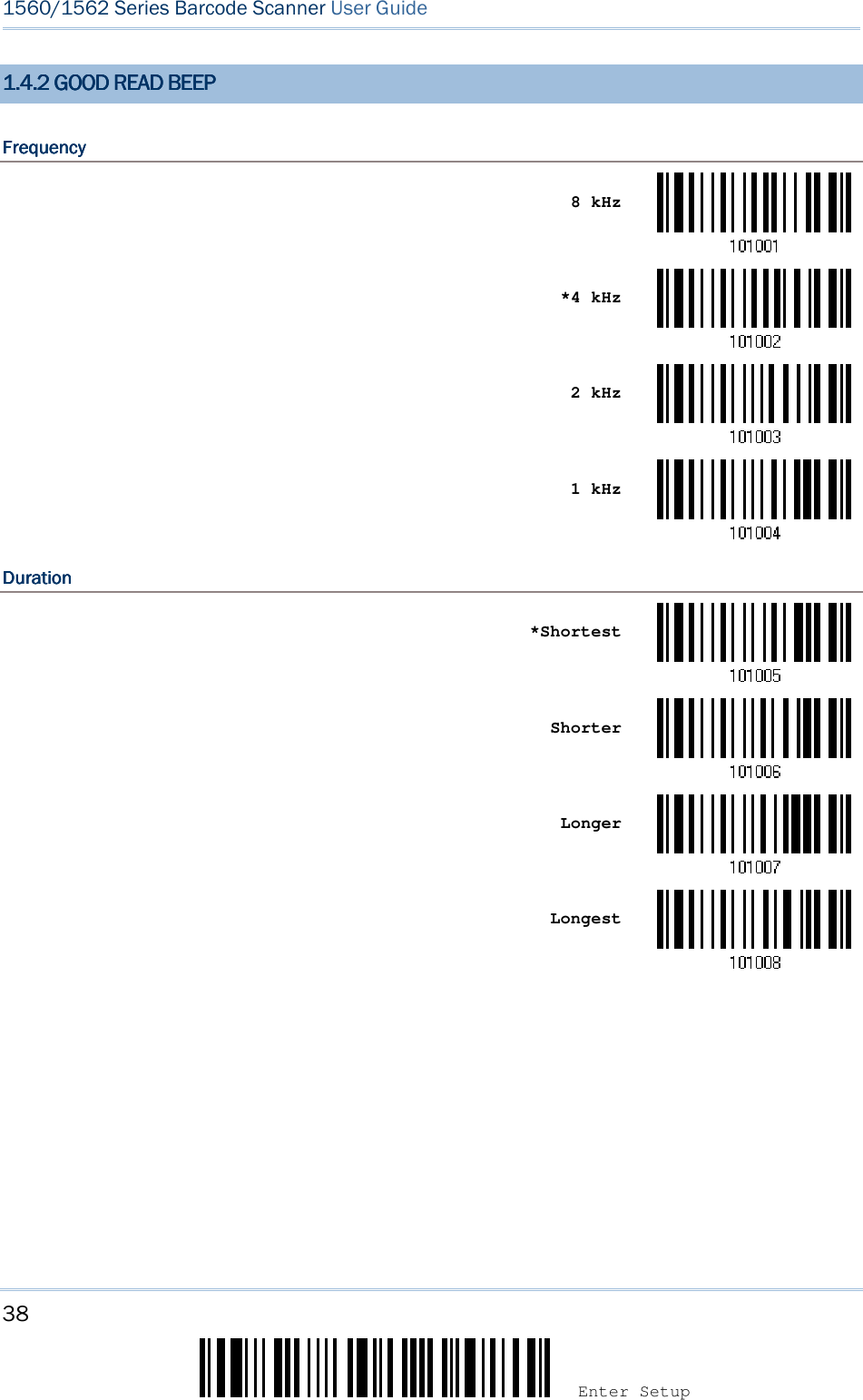
![5 Update ! ! ! ! [[[[] ] ] ] Heading 1 Heading 1 Heading 1 Heading 1 CHARGING THE BATTERYCHARGING THE BATTERYCHARGING THE BATTERYCHARGING THE BATTERY VIA VIA VIA VIA 3656365636563656 CRADLECRADLECRADLECRADLE The battery may not be charged to full for shipment. When you first receive the package, you will need to charge the battery to full before using the scanner. When using the RS-232 cable, it takes approximately 5 hours to charge the battery to full (from the power adaptor). Note: Battery charging stops when the temperature drops below 0°C or exceeds 40°C. It is recommended to charge the battery at room temperature (18°C to 25°C) for optimal performance. 1) Install the battery to the scanner. 2) Seat the scanner in the 3656 CRADLE stand. 3) Connect the 3656 CRADLE stand to your computer or notebook via the USB or RS-232 cable. 4) Connect the power supply cord from 3656 CRADLE to a proper power outlet. Warning: RS-232/USB interface both require connecting the power supply cord. When the stand is solely on USB power, the current may be insufficient for it to function normally. You must connect the power supply cord. 5) The LED for power indication on 3656 CRADLE will become solid red. 6) The scanner LED will be flashing red during charging. When the charging is done, the LED will turn off. When charging error occurs, the LED will turn solid red. 7) The LED for communications on 3656 CRADLE will first become solid blue while initializing. Refer to the table above for details on different stage of communications. The two pivot bolts need to be tightened, or charging error may occur.](https://usermanual.wiki/CipherLab/3656CRADLE/User-Guide-3879656-Page-23.png)
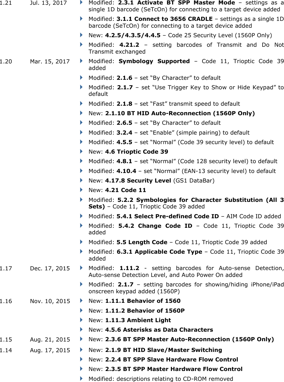
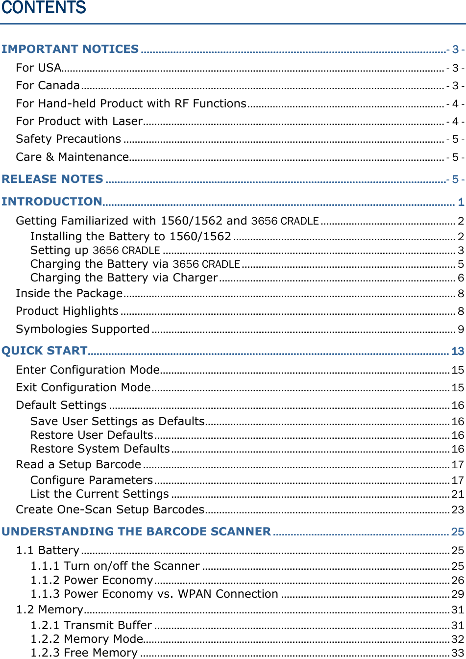
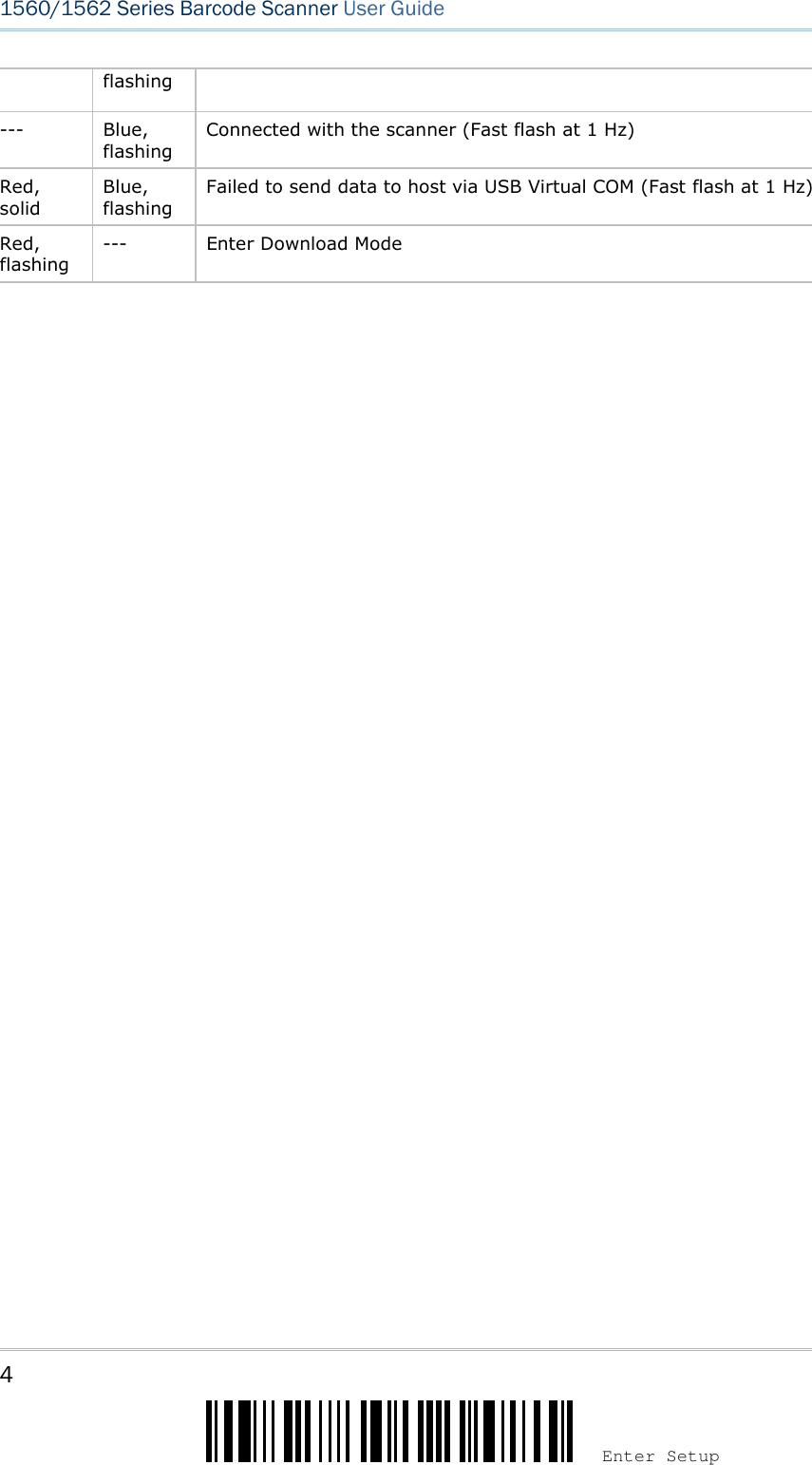
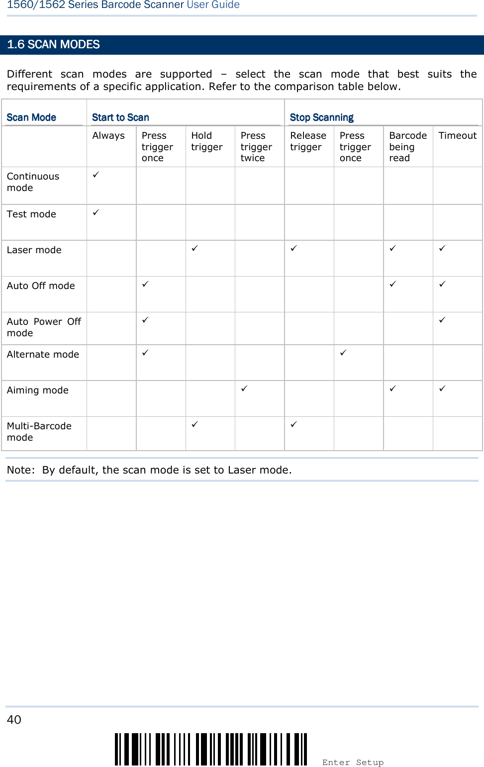
![7 Update ! ! ! ! [[[[] ] ] ] Heading 1 Heading 1 Heading 1 Heading 1 Status LEDStatus LEDStatus LEDStatus LED MeaningMeaningMeaningMeaning Red, solid --- Charger power ON (LED on for 0.5 second) Red, solid --- Charging battery --- Green, solid Charging done Red, solid Green, solid Pre-charging when battery voltage under 3V (Typical) --- --- Power or battery not ready](https://usermanual.wiki/CipherLab/3656CRADLE/User-Guide-3879656-Page-25.png)
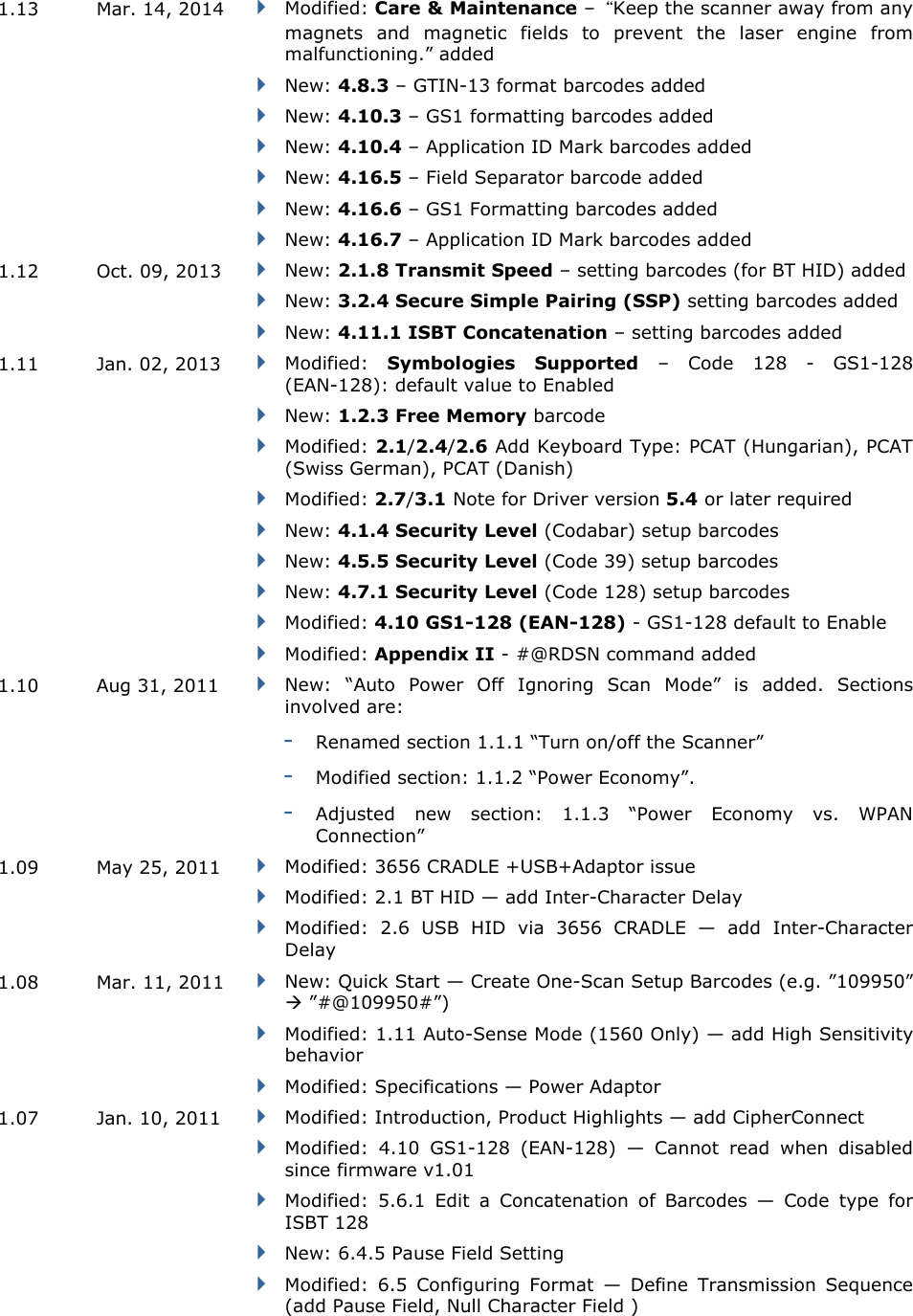
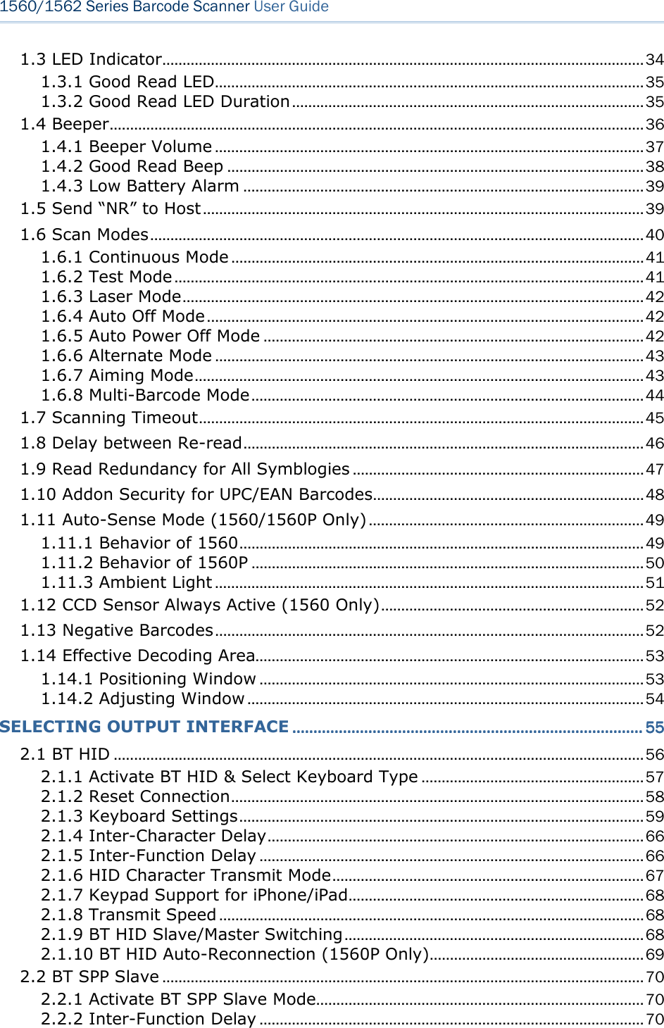
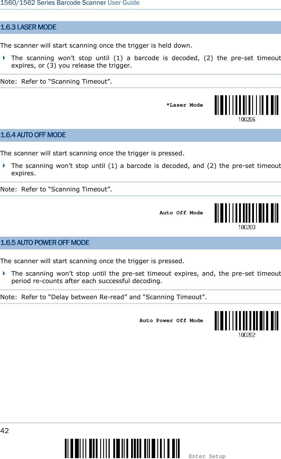
![9 Update ! ! ! ! [[[[] ] ] ] Heading 1 Heading 1 Heading 1 Heading 1 SYMBOLOGIES SYMBOLOGIES SYMBOLOGIES SYMBOLOGIES SUPPORTEDSUPPORTEDSUPPORTEDSUPPORTED Most of the popular barcode symbologies are supported, as listed below. Each can be individually enabled or disabled. The scanner will automatically discriminate and recognize all the symbologies that are enabled. Refer to Chapter 4 Changing Symbology Settings for details of each symbology. Symbologies Supported: Enable/DisableSymbologies Supported: Enable/DisableSymbologies Supported: Enable/DisableSymbologies Supported: Enable/Disable DefaultDefaultDefaultDefault Codabar Enabled Code 93 Enabled MSI Disabled Plessey Disabled Telepen Disabled Code 128 Code 128 Enabled GS1-128 (EAN-128) Enabled ISBT 128 Enabled Note: Starting from firmware version 1.01, ISBT 128 is enabled by default. Code 2 of 5 Industrial 25 Enabled Interleaved 25 Enabled Matrix 25 Disabled Code 3 of 9 Code 39 Enabled Italian Pharmacode Disabled French Pharmacode Disabled Trioptic Code 39 Disabled EAN/UPC EAN-8 Enabled EAN-8 Addon 2 Disabled EAN-8 Addon 5 Disabled EAN-13 Enabled EAN-13 & UPC-A Addon 2 Disabled EAN-13 & UPC-A Addon 5 Disabled ISBN Disabled UPC-E0 Enabled UPC-E1 Disabled UPC-E Addon 2 Disabled UPC-E Addon 5 Disabled UPC-A Enabled](https://usermanual.wiki/CipherLab/3656CRADLE/User-Guide-3879656-Page-27.png)
![11 Update ! ! ! ! [[[[] ] ] ] Heading 1 Heading 1 Heading 1 Heading 1](https://usermanual.wiki/CipherLab/3656CRADLE/User-Guide-3879656-Page-29.png)
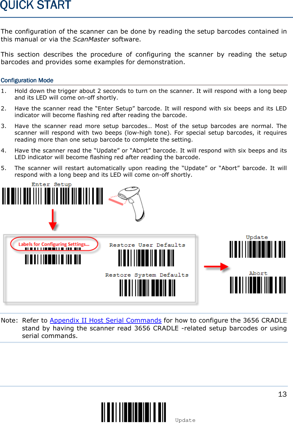
![15 Update ! ! ! ! [[[[] ] ] ] Heading 1 Heading 1 Heading 1 Heading 1 ENTER CONFIGURATION ENTER CONFIGURATION ENTER CONFIGURATION ENTER CONFIGURATION MODEMODEMODEMODE For the scanner to enter the configuration mode, you must have it read the “Enter Setup” barcode, which can be located at the bottom of almost every even page of this manual. The scanner will respond with six beeps and its LED indicator will become flashing red after reading the barcode. Enter Setup For configuring scanner parameters, see “Read a Setup Barcode” below. EXIT CONFIGURATION MEXIT CONFIGURATION MEXIT CONFIGURATION MEXIT CONFIGURATION MODEODEODEODE For the scanner to save settings and exit the configuration mode, you must have it read the “Update” barcode, which can be located at the bottom of almost every odd page of this manual. If you want to exit the configuration mode without saving any changes, have the scanner read the “Abort” barcode instead. Just like reading the “Enter Setup” barcode, the scanner will respond with six beeps and its LED indicator will become flashing red after reading the barcode. Wait for a few seconds for the scanner to restart itself. Update Abort](https://usermanual.wiki/CipherLab/3656CRADLE/User-Guide-3879656-Page-33.png)
![17 Update ! ! ! ! [[[[] ] ] ] Heading 1 Heading 1 Heading 1 Heading 1 READ A SETUP READ A SETUP READ A SETUP READ A SETUP BARCODEBARCODEBARCODEBARCODE CONFIGURE PARAMETERSCONFIGURE PARAMETERSCONFIGURE PARAMETERSCONFIGURE PARAMETERS For most of the scanner parameters, only one read is required to set them to new values. The scanner will respond with two beeps (low-high tone) when each parameter is set successfully. But for a number of special parameters, multiple reads are required to complete the setting. In this case, the scanner will respond with a short beep to indicate it needs to read more setup barcodes. These special parameters may require reading one or more setup barcodes, such as Numeric barcodes, say, for keyboard type, inter-character delay, length qualification Hexadecimal barcodes, say, for character strings as prefix, suffix, etc. When “BT HID”, “USB HID” or “Keyboard Wedge” is configured for interface, Key Type and Key Status will then become applicable. You may decide whether or not to change key status when “Normal Key” is selected for Key Type. To complete the configuration of these special parameters, it requires reading the “Validate” barcode, and the scanner will respond with two beeps (low-high tone) to indicate the input values are validated.](https://usermanual.wiki/CipherLab/3656CRADLE/User-Guide-3879656-Page-35.png)
![19 Update ! ! ! ! [[[[] ] ] ] Heading 1 Heading 1 Heading 1 Heading 1 The example below shows how to set numeric parameters: StepsStepsStepsSteps ActionActionActionAction User Feedback if SuccessfulUser Feedback if SuccessfulUser Feedback if SuccessfulUser Feedback if Successful 1 Power on the scanner... The scanner will respond with a long beep (high tone) and its LED indicator will become solid red and go off quickly. 2 Enter the Configuration Mode… The scanner will respond with six beeps (high-low tone repeats three times), and its LED indicator will become flashing red. 3 Read a Setup barcode... For example, The scanner will respond with two beeps (low-high tone) if reading a normal setup barcode. The scanner will respond with one short beep if reading a special setup barcode such as “Max. Length”, indicating the setup requires reading more barcodes. Read the “Decimal Value” barcode(s). Refer to Appendix IV “Decimal System” The scanner will respond with two beeps (low-high tone) when the input values are validated. 4 Exit the Configuration Mode… OR Same as for Enter the Configuration Mode. 5 The scanner will automatically restart itself… Same as for Power on the scanner. Normal setup barcode Special setup barcode Decimal barcodes Normal setup barcode](https://usermanual.wiki/CipherLab/3656CRADLE/User-Guide-3879656-Page-37.png)
![21 Update ! ! ! ! [[[[] ] ] ] Heading 1 Heading 1 Heading 1 Heading 1 LIST THE CURRENT SETLIST THE CURRENT SETLIST THE CURRENT SETLIST THE CURRENT SETTINGSTINGSTINGSTINGS The current settings of all scanner parameters can be sent to the host computer for user inspection. The listing includes pages as shown below. You can select the page of interest by having the scanner read the “List Page x” barcode. The scanner will respond with two beeps (low-high tone) and send the selected page to the host immediately. List settings regarding Firmware Version, Serial Number, Interface, Buzzer, and Other Scanner Parameters List Page 1 List settings regarding Prefix, Suffix, and Length Code Setting List Page 2 List settings regarding Code ID List Page 3 List settings regarding: Readable Symbologies List Page 4 List settings regarding Symbology Parameters (1/3) List Page 5 List settings regarding Symbology Parameters (2/3) List Page 6 List settings regarding Symbology Parameters (3/3) List Page 7 List settings regarding Editing Format 1 List Page 8 List settings regarding Editing Format 2 List Page 9 List settings regarding Editing Format 3 List Page 10](https://usermanual.wiki/CipherLab/3656CRADLE/User-Guide-3879656-Page-39.png)
![23 Update ! ! ! ! [[[[] ] ] ] Heading 1 Heading 1 Heading 1 Heading 1 CREATE ONECREATE ONECREATE ONECREATE ONE----SCAN SETUP BARCODESSCAN SETUP BARCODESSCAN SETUP BARCODESSCAN SETUP BARCODES The fact is most of the scanner parameters require only one read for setting new values. To facilitate configuring the scanner, you may create One-Scan setup barcodes for use. The requirements of a One-Scan setup barcode are: a prefix of the “#@” characters the six digits of command parameters a suffix of the “#”character For example, the scanner needs reading three setup barcodes for the command parameter “109952” to take effect: Enter Setup List Page 3 Update Now, it requires only one read: One-Scan Setup Barcode for 109952 Note: The scanner will restart automatically upon reading the One-Scan setup barcode for (1) changing the interface or (2) setting memory mode, enable or disable. It will respond with a long beep and its LED will come on-off shortly.](https://usermanual.wiki/CipherLab/3656CRADLE/User-Guide-3879656-Page-41.png)
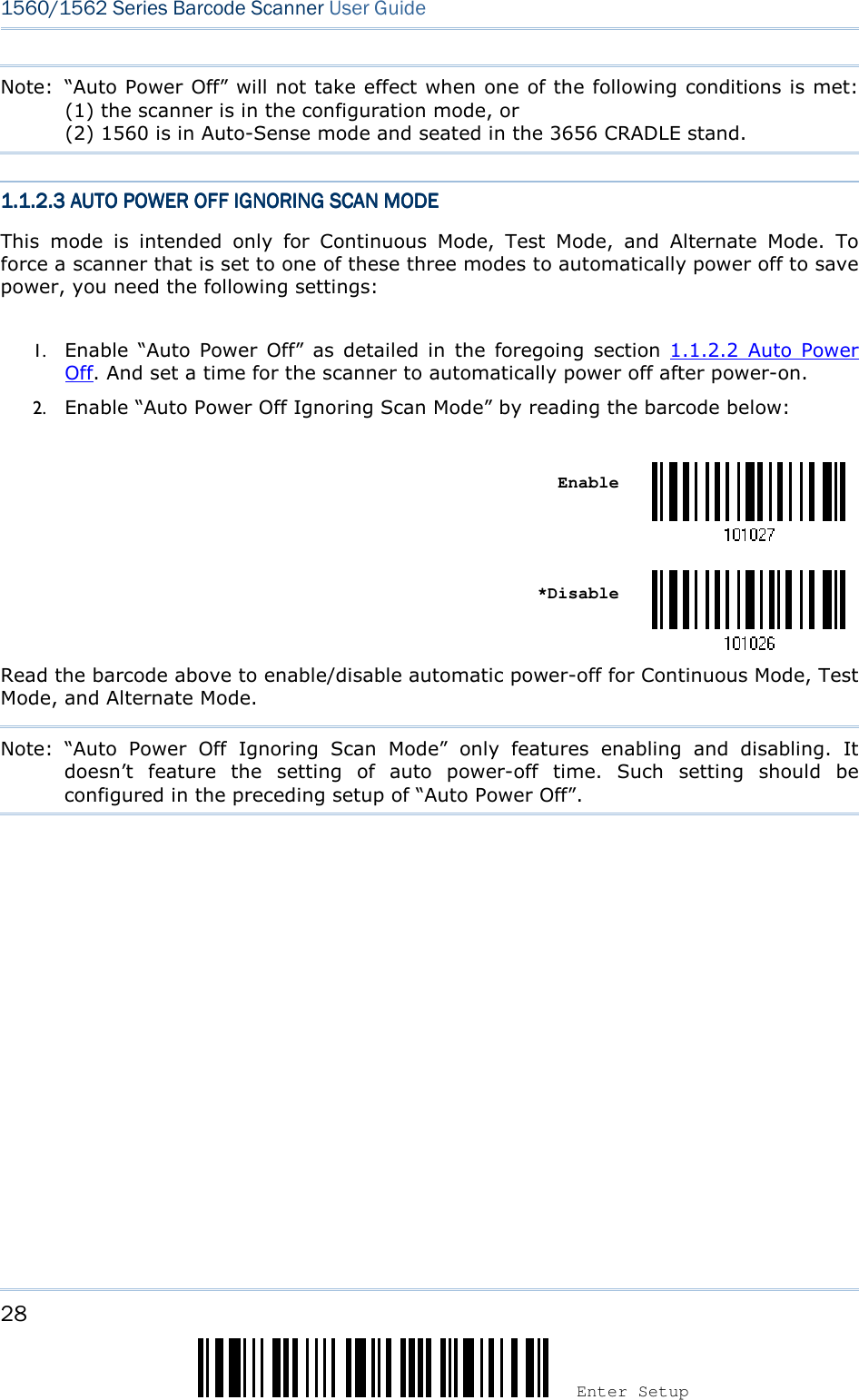
![27 Update Chapter 1 ! ! ! ! [[[[] ] ] ] Heading 1 Heading 1 Heading 1 Heading 1 Note: Power-Saving won’t take effect when one of the following conditions is met: (1) the scanner has already established a BT HID/SPP connection, (2) the scanner is in the configuration mode, (3) the scan mode is set to Test, Continuous or Alternate Mode, (4) 1560 is in Auto-Sense mode and seated in the 3656 CRADLE stand, or (5) the setting value of Power-Saving is greater than that of Auto Power Off. 1.1.2.2 AUTO POWER O1.1.2.2 AUTO POWER O1.1.2.2 AUTO POWER O1.1.2.2 AUTO POWER OFFFFFFFF For the scanner to save power, further to setting up “Power-Saving” mode, you may also need to enable “Auto Power Off”, which deals with a time for the scanner to automatically power off after power-on. Make the configuration that best suits your application while noting the following points: Auto Power Off: 1~254 minutes configurable. 0= Disable. 1. By default, the scanner automatically shuts down 10 minutes after power-on. 2. If Auto Power Off isn’t desired, set the parameter to 0 to disable it. 3. When the scan mode is set to any of Continuous Mode, Test Mode, and Alternate Mode, you need to enable “Auto Power Off Ignoring Scan Mode” in addition to enabling “Auto Power Off”. See the following section 1.1.2.3 Auto Power Off Ignoring Scan Mode to achieve auto power off. Note: When the scanner is set to any scan mode other than Continuous Mode, Test Mode and Alternate Mode, you can skip “Auto Power Off Ignoring Scan Mode”. Auto Power Off after 0~254 min. (*10) 1) Read the barcode above to enable the scanner to automatically turn off at a specified time after power-on. 2) Assign the auto power off time by reading the “Decimal Value” barcode on page 241. For example, read “1” and “5” for the scanner to automatically turn off after idleness of 15 minutes. 3) Read the “Validate” barcode on the same page to complete this setting.](https://usermanual.wiki/CipherLab/3656CRADLE/User-Guide-3879656-Page-45.png)
![29 Update Chapter 1 ! ! ! ! [[[[] ] ] ] Heading 1 Heading 1 Heading 1 Heading 1 1.1.1.1.1.3 1.3 1.3 1.3 POWER ECONOMY VS.POWER ECONOMY VS.POWER ECONOMY VS.POWER ECONOMY VS. WPAN CONNECTIONWPAN CONNECTIONWPAN CONNECTIONWPAN CONNECTION Before the scanner can communicate with the host computer, Bluetooth connection (or WPAN connection) needs to be established. The scanner’s power economy always accommodates itself to the establishment of the WPAN connection. The following describes how the scanner carries out power economy before and after the establishment of the WPAN connection: BBBBefefefefore establishing a WPAN connection successfullyore establishing a WPAN connection successfullyore establishing a WPAN connection successfullyore establishing a WPAN connection successfully………… 1. The scanner stays active for a specified period of time (2 minutes by default) for the following scenarios. The CPU runs at full speed, and the LED blinks blue (On/Off ratio 0.5 s: 0.5 s). (a) waiting for a connection request from the host (BT SPP Slave Mode) (b) trying to connect to the host (BT HID or BT SPP Master Mode) (c) trying to connect to 3656 CRADLE 2. If the scanner fails to connect within 2 minutes, it becomes inactive to save power for the remaining period of time (the specified “Auto Power Off” value minus 2 minutes). The CPU starts to run at low speed, and the LED begins to blink red (On/Off ratio 0.3 s: 2.5 s). Pull the trigger to wake up the scanner when it becomes inactive, and the scanner will become active again. 3. If it fails to connect again and again, and finally stays inactive until the specified Auto Power Off time elapses, the scanner will automatically turn off in order to conserve battery power. Pull down the trigger for about 2 seconds to turn it on again. Note: For scenarios (a) and (b) in step 1, you may need to search for the scanner again on your computer. AfterAfterAfterAfter establishing a WPAN connection successfullyestablishing a WPAN connection successfullyestablishing a WPAN connection successfullyestablishing a WPAN connection successfully………… 1. Once a WPAN connection is established successfully, the scanner will stay active for a specified period of time (2 minutes by default) for data transmission. The CPU runs at full speed, and the LED blinks blue (On/Off ratio 0.02 s: 3 s). 2. If the scanner stays idle for 2 minutes (default), it will then turn inactive to save power for the remaining period of time (the specified “Auto Power Off” value minus 2 minutes). The CPU runs at low speed, and the LED is blinking red (On/Off ratio 0.3 s: 2.5 s). Pull the trigger to wake up the scanner when it becomes inactive, then the scanner will stay active again. For BT HID or SPP, the scanner automatically shuts down after the configured “Auto Power Off” time without the transition from full CPU speed to low CPU speed. However, when connecting with 3656 CRADLE, the scanner will go through the transition in order to save power. 3. If the scanner first becomes idle and finally stays inactive until the specified Auto Power Off time is up, the scanner will automatically turn off in order to conserve battery power. You will hear three short beeps, tone descending from high to low. Pull down the trigger for about 2 seconds to turn it on again. For BT HID, the scanner resumes the connection with the host upon powering on again, as long as the host application is running. You will hear three short beeps, tone ascending](https://usermanual.wiki/CipherLab/3656CRADLE/User-Guide-3879656-Page-47.png)
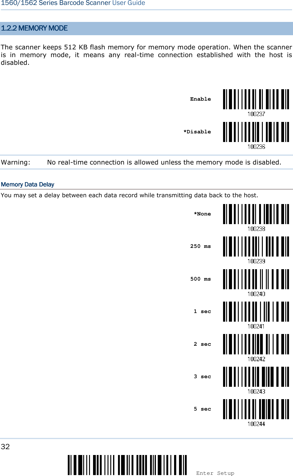
![31 Update Chapter 1 ! ! ! ! [[[[] ] ] ] Heading 1 Heading 1 Heading 1 Heading 1 1.2 1.2 1.2 1.2 MEMORYMEMORYMEMORYMEMORY The collected data can be sent back to a host computer one by one via the WPAN connection or stored in flash memory when the scanner is set to Memory mode. 1.2.1 1.2.1 1.2.1 1.2.1 TRANSMIT BUFTRANSMIT BUFTRANSMIT BUFTRANSMIT BUFFERFERFERFER By default, transmit buffer is enabled and for use when the scanner is out of range. Upon reading a barcode successfully within range, the scanner responds with one short beep (high tone) and its LED indicator becomes solid green and goes off quickly. However, the host computer may not receive the data immediately if getting out of range. With the 4 KB transmit buffer, the scanner can ignore the transmission status and keep on reading barcodes until the buffer is full. When transmit buffer is enabled…When transmit buffer is enabled…When transmit buffer is enabled…When transmit buffer is enabled… If the scanner is out of range, it will respond with two short beeps, high-low tone, upon reading a barcode successfully. When transmit buffer is full, the scanner will respond with one long beep (low tone) and its LED indicator will become solid red and go off quickly. You are advised to get back to range. When transmit buffer is disabled…When transmit buffer is disabled…When transmit buffer is disabled…When transmit buffer is disabled… If the scanner is out of range, it will respond with one long beep (low tone) and its LED indicator will become solid red and go off quickly. You are advised to get back to range. *Enable Disable Note: The 4 KB transmit buffer on the scanner can hold as many as 256 scans based on EAN-13 barcodes. Data will be cleared out once the scanner is turned off or running out of battery power!](https://usermanual.wiki/CipherLab/3656CRADLE/User-Guide-3879656-Page-49.png)
![33 Update Chapter 1 ! ! ! ! [[[[] ] ] ] Heading 1 Heading 1 Heading 1 Heading 1 8 sec Send DataSend DataSend DataSend Data The 512 KB flash memory on the scanner can store up to 32,768 scans based on EAN-13 barcodes. When it is used up, the scanner will respond with two short beeps (high-low tone) as a warning. You are advised to send data to the host immediately by having the scanner read the “Send Data” barcode below. It will resume the previous WPAN connection with the host temporarily. Send Data Clear Data & ConfirmClear Data & ConfirmClear Data & ConfirmClear Data & Confirm Even though data has been sent back to the host, the flash memory is still occupied unless you erase the memory by having the scanner read two barcodes – “Clear Data” and “Confirm”. 1. Read the “Clear Data” barcode to clear the flash memory. 2. Read the “Confirm” barcode to confirm the action. Clear Data Confirm 1.2.3 FREE MEMORY1.2.3 FREE MEMORY1.2.3 FREE MEMORY1.2.3 FREE MEMORY In memory mode, you can scan the barcode below to show the available capacity of the flash memory in percentage terms. Spare memory](https://usermanual.wiki/CipherLab/3656CRADLE/User-Guide-3879656-Page-51.png)
![35 Update Chapter 1 ! ! ! ! [[[[] ] ] ] Heading 1 Heading 1 Heading 1 Heading 1 1.3.1.3.1.3.1.3.1111 GOOD READ LEDGOOD READ LEDGOOD READ LEDGOOD READ LED *Enable Good Read LED Disable Good Read LED 1.3.2 GOOD READ LED 1.3.2 GOOD READ LED 1.3.2 GOOD READ LED 1.3.2 GOOD READ LED DURATIONDURATIONDURATIONDURATION By default, the Good Read LED stays on for 40 milliseconds. Specify a value, ranging from 1 to 254 in units of 10 milliseconds. Good Read LED Time-out after 0.01~2.54 sec. (*40 ms) 1) Read the barcode above to specify the time interval before the Good Read LED goes off. 2) Read the “Decimal Value” barcode on page 241. For example, read “1” and “5” for the Good Read LED to go off after 150 milliseconds. 3) Read the “Validate” barcode on the same page to complete this setting.](https://usermanual.wiki/CipherLab/3656CRADLE/User-Guide-3879656-Page-53.png)
![37 Update Chapter 1 ! ! ! ! [[[[] ] ] ] Heading 1 Heading 1 Heading 1 Heading 1 1.4.1.4.1.4.1.4.1111 BEEPER BEEPER BEEPER BEEPER VOLUMEVOLUMEVOLUMEVOLUME Mute Minimum Volume Medium Volume *Maximum Volume](https://usermanual.wiki/CipherLab/3656CRADLE/User-Guide-3879656-Page-55.png)
![39 Update Chapter 1 ! ! ! ! [[[[] ] ] ] Heading 1 Heading 1 Heading 1 Heading 1 1.4.1.4.1.4.1.4.3333 LOW BATTERY ALARMLOW BATTERY ALARMLOW BATTERY ALARMLOW BATTERY ALARM By default, it will activate the beeper to give a warning when the battery charge gets low. In order to prevent data loss, you are advised to replace the battery immediately when you hear two short beeps (high tone). No Alarm *Low Battery Alarm 1.51.51.51.5 SEND “NR” TO HOSTSEND “NR” TO HOSTSEND “NR” TO HOSTSEND “NR” TO HOST The scanner can send the “NR” string to the host to notify the No Read event. Enable *Disable](https://usermanual.wiki/CipherLab/3656CRADLE/User-Guide-3879656-Page-57.png)
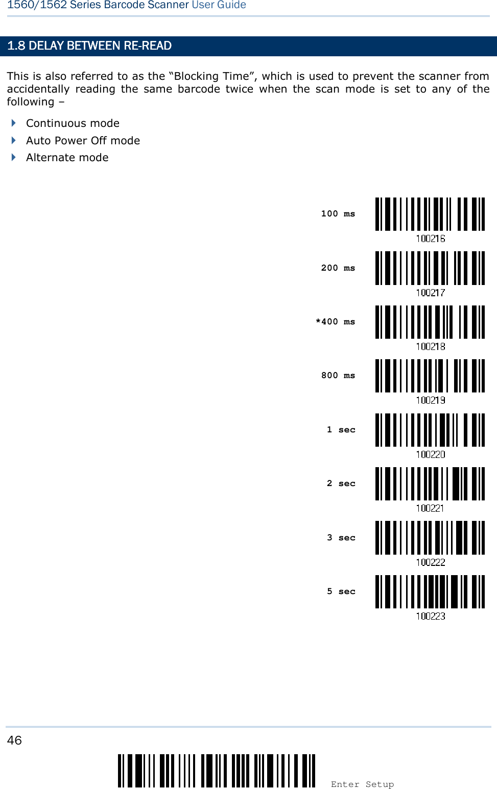
![41 Update Chapter 1 ! ! ! ! [[[[] ] ] ] Heading 1 Heading 1 Heading 1 Heading 1 1.1.1.1.6666....1111 CONTINUOUS MODECONTINUOUS MODECONTINUOUS MODECONTINUOUS MODE The scanner is always scanning. After a successful decoding, the removal of barcode is required. It is not allowed to proceed to decode until the decoding delay time has passed. To decode the same barcode repeatedly, move away the barcode and put it back again and again for scanning. Note: Refer to “Delay between Re-read”. Continuous Mode Decoding DelayDecoding DelayDecoding DelayDecoding Delay Set the time interval between each decoding. *Disable 0.5 sec 1 sec 2 sec 1.1.1.1.6666.2.2.2.2 TEST MODETEST MODETEST MODETEST MODE The scanner is always scanning. Capable of decoding the same barcode repeatedly without removing it, for testing purpose. Test Mode](https://usermanual.wiki/CipherLab/3656CRADLE/User-Guide-3879656-Page-59.png)
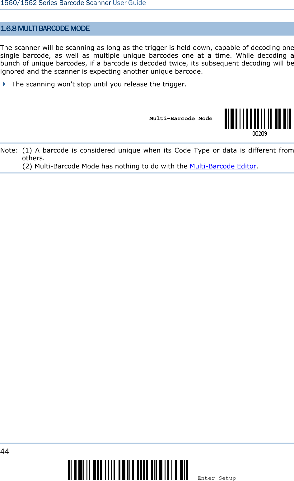
![43 Update Chapter 1 ! ! ! ! [[[[] ] ] ] Heading 1 Heading 1 Heading 1 Heading 1 1.6.6 ALTERNATE MODE1.6.6 ALTERNATE MODE1.6.6 ALTERNATE MODE1.6.6 ALTERNATE MODE The scanner will start scanning once the trigger is pressed The scanning won't stop until you press the trigger again. Alternate Mode 1.1.1.1.6666....7777 AIMING MODEAIMING MODEAIMING MODEAIMING MODE The scanner will aim at a barcode once the trigger is pressed, and start scanning when the trigger is pressed again within one second. The scanning won't stop until (1) a barcode is decoded, and (2) the pre-set timeout expires. Aiming Mode Aiming TimeoutAiming TimeoutAiming TimeoutAiming Timeout You can limit the aiming time interval (1~15). By default, the scanner time-out is set to 1 second. Aiming Time-out after 1~15 sec. (*1) 1. Read the barcode above to specify the time interval before aiming ends. (It is set to 1 by default.) 2. Read the “Decimal Value” barcode on page 241. For example, read “1” and “0” for the scanner to automatically shut down after idleness for 10 seconds. 3. Read the “Validate” barcode on the same page to complete this setting.](https://usermanual.wiki/CipherLab/3656CRADLE/User-Guide-3879656-Page-61.png)
![45 Update Chapter 1 ! ! ! ! [[[[] ] ] ] Heading 1 Heading 1 Heading 1 Heading 1 1.1.1.1.7777 SCANNSCANNSCANNSCANNINGINGINGING TIMEOUTTIMEOUTTIMEOUTTIMEOUT Specify the scanning time interval (1~254 sec.; 0= Disable) when the scan mode is set to any of the following – Laser mode Auto Off mode Auto Power Off mode Aiming mode Scanner Time-out after 0~254 sec. (*10) 1) Read the barcode above to specify the time interval before the scan engine times out. 2) Read the “Decimal Value” barcode on page 241. For example, read “1” and “5” for the scanner to automatically shut down after idleness of 15 seconds. 3) Read the “Validate” barcode on the same page to complete this setting.](https://usermanual.wiki/CipherLab/3656CRADLE/User-Guide-3879656-Page-63.png)
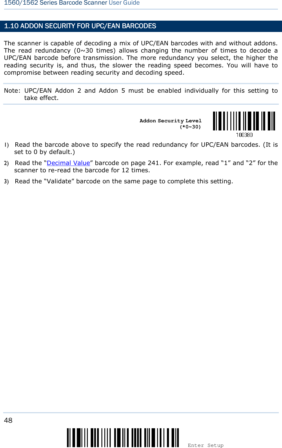
![47 Update Chapter 1 ! ! ! ! [[[[] ] ] ] Heading 1 Heading 1 Heading 1 Heading 1 1.1.1.1.9999 READ REDUNDAREAD REDUNDAREAD REDUNDAREAD REDUNDANCY FOR ALL SYMBLOGINCY FOR ALL SYMBLOGINCY FOR ALL SYMBLOGINCY FOR ALL SYMBLOGIESESESES Select the level of reading security. For example, If “No Redundancy” is selected, one successful decoding will make the reading valid and induce the “READER Event”. If “Three Times” is selected, it will take a total of four consecutive successful decoding of the same barcode to make the reading valid. The higher the reading security is (that is, the more redundancy the user selects), the slower the reading speed gets. It is obvious that the more redundancy you select, the higher the reading security is, and thus, the slower the reading speed becomes. You will have to compromise between reading security and decoding speed. *No Redundancy One Time Two Times Three Times](https://usermanual.wiki/CipherLab/3656CRADLE/User-Guide-3879656-Page-65.png)
![49 Update Chapter 1 ! ! ! ! [[[[] ] ] ] Heading 1 Heading 1 Heading 1 Heading 1 1.11 AUTO1.11 AUTO1.11 AUTO1.11 AUTO----SENSE MODE (1560SENSE MODE (1560SENSE MODE (1560SENSE MODE (1560/1560P/1560P/1560P/1560P ONLY)ONLY)ONLY)ONLY) 1.11.1 BEHAVIOR OF 11.11.1 BEHAVIOR OF 11.11.1 BEHAVIOR OF 11.11.1 BEHAVIOR OF 1560560560560 For 1560, this mode is available when you seat the scanner in the Auto-sense stand and scan the Enable barcode. When you enable this mode, it will force the scanner to apply Laser mode as the scan mode. However, it works slightly different from the original Laser mode. Now the scanner will be expecting barcodes as long as it is seated in the Auto-sense stand, as shown below. Whenever a barcode is brought within range, the scanner will be able to decode it. Enable *Disable Note: Enabling Auto-sense will force the scanner into Laser mode. To stop this mode, you may remove the scanner from the stand or have the scanner read the “Disable (Auto-sense)” barcode above. It will then return to Laser mode. If Laser mode is not desired, proceed to select a scan mode best suits your application. Note: To get Auto-sense mode work, you must connect both the power supply cord and the interface cable to the stand; supplying the only USB power is insufficient.](https://usermanual.wiki/CipherLab/3656CRADLE/User-Guide-3879656-Page-67.png)
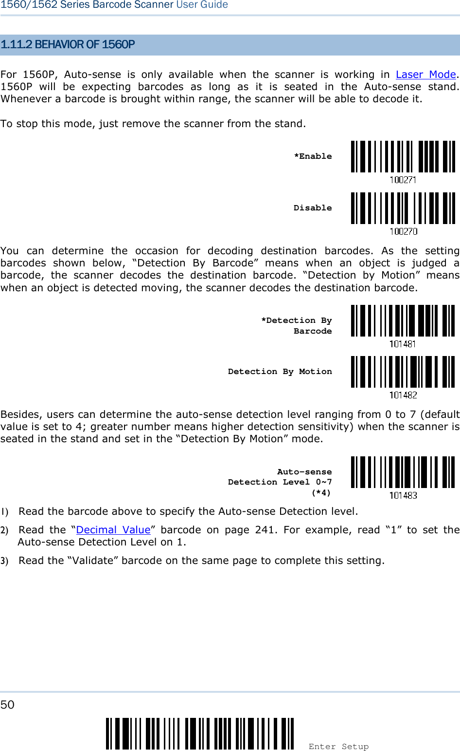
![51 Update Chapter 1 ! ! ! ! [[[[] ] ] ] Heading 1 Heading 1 Heading 1 Heading 1 For your convenience, 1560P is designed to power on automatically in Auto-sense mode when you seat it in the stand connecting to the power socket. By default, this mechanism is disabled. You have to enable it by having the scanner read the Enable barcode below. Enable *Disable 1.11.3 AMBIENT LIGHT1.11.3 AMBIENT LIGHT1.11.3 AMBIENT LIGHT1.11.3 AMBIENT LIGHT When the ambient light is too dim to activate the sensor, you may have the scanner read the “High Sensitivity” barcode to improve performance. Starting from firmware version 1.23, it will emit scan beam every 300 milliseconds when “High Sensitivity” is enabled. High Sensitivity *Normal Note: If the ambient light is under 100 lux, we suggest that you either add lighting or use Continuous mode instead.](https://usermanual.wiki/CipherLab/3656CRADLE/User-Guide-3879656-Page-69.png)
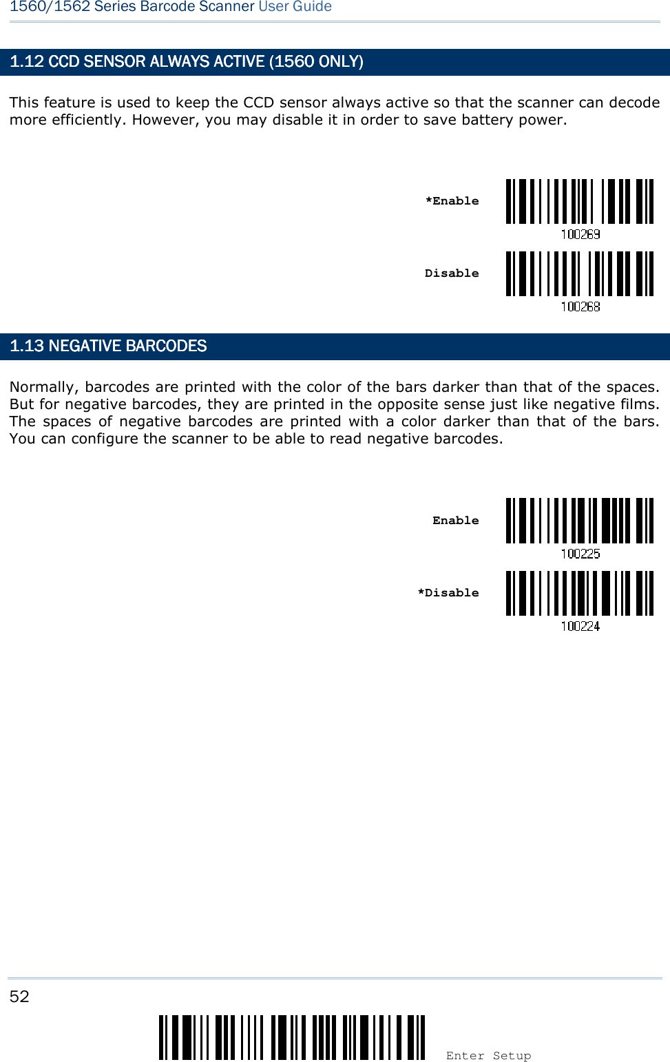
![53 Update Chapter 1 ! ! ! ! [[[[] ] ] ] Heading 1 Heading 1 Heading 1 Heading 1 1.1.1.1.14141414 EFFECTIVE DECODING AEFFECTIVE DECODING AEFFECTIVE DECODING AEFFECTIVE DECODING AREAREAREAREA By default, the effective decoding area is 100% covered by the scanned area. However, you may narrow down the decoding area to prevent reading the wrong barcode when a number of barcodes are printed closely. The scanner will only read barcodes that appear in the effective decoding area. Read the barcode “Centering On” and specify the percentage to narrow down the decoding area. For example, read “Left 10%” and then “Right 30%” for the scanner to decode barcode “A” only. 1.1.1.1.14141414.1 POSITIONING WINDO.1 POSITIONING WINDO.1 POSITIONING WINDO.1 POSITIONING WINDOWWWW Centering On *Centering Off](https://usermanual.wiki/CipherLab/3656CRADLE/User-Guide-3879656-Page-71.png)

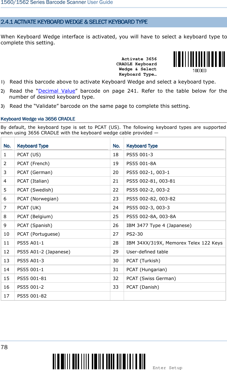
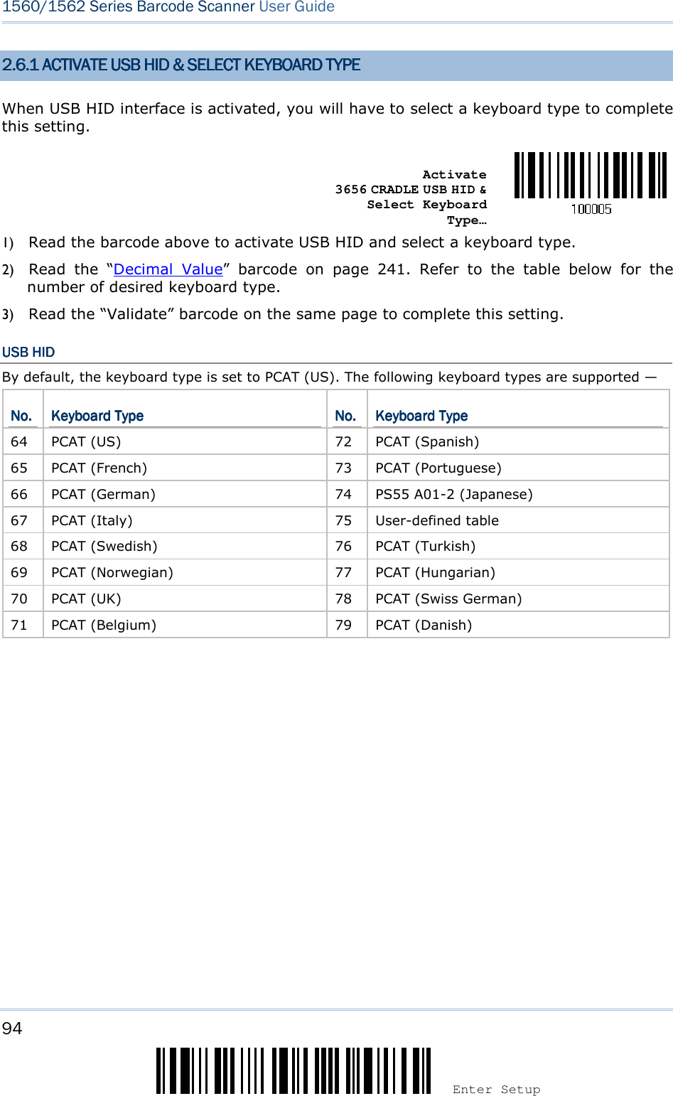
![57 Update Chapter 2 ! ! ! ! [[[[] ] ] ] Heading 1 Heading 1 Heading 1 Heading 1 2222.1.1.1.1.1 ACTIVATE .1 ACTIVATE .1 ACTIVATE .1 ACTIVATE BT BT BT BT HID & SELECT KEYBOARHID & SELECT KEYBOARHID & SELECT KEYBOARHID & SELECT KEYBOARD TYPED TYPED TYPED TYPE When BT HID interface is activated, you will have to select a keyboard type to complete this setting. By default, BT HID is activated on the scanner, and the keyboard type is set to PCAT (US). Activate BT HID & Select Keyboard Type… 1) Read the barcode above to activate BT HID and select a keyboard type. 2) Read the “Decimal Value” barcode on page 241. Refer to the table below for the number of desired keyboard type. 3) Read the “Validate” barcode on the same page to complete this setting. BT HIDBT HIDBT HIDBT HID By default, the keyboard type is set to PCAT (US). The following keyboard types are supported — No.No.No.No. Keyboard TypeKeyboard TypeKeyboard TypeKeyboard Type No.No.No.No. Keyboard TypeKeyboard TypeKeyboard TypeKeyboard Type 64 PCAT (US) 72 PCAT (Spanish) 65 PCAT (French) 73 PCAT (Portuguese) 66 PCAT (German) 74 PS55 A01-2 (Japanese) 67 PCAT (Italy) 75 User-defined table 68 PCAT (Swedish) 76 PCAT (Turkish) 69 PCAT (Norwegian) 77 PCAT (Hungarian) 70 PCAT (UK) 78 PCAT (Swiss German) 71 PCAT (Belgium) 79 PCAT (Danish)](https://usermanual.wiki/CipherLab/3656CRADLE/User-Guide-3879656-Page-75.png)
![59 Update Chapter 2 ! ! ! ! [[[[] ] ] ] Heading 1 Heading 1 Heading 1 Heading 1 2.2.2.2.1111....3333 KEYBOARD SETTINGSKEYBOARD SETTINGSKEYBOARD SETTINGSKEYBOARD SETTINGS Alphabets Layout Digits Layout Capital Lock Type Capital Lock Setting Alphabets Transmission Digits Transmission Note: BT HID does not support these functions on PDAs – (1) Capital Lock Setting: Auto Detection (2) Digits Transmission: Numeric Key Alphabets LayoutAlphabets LayoutAlphabets LayoutAlphabets Layout By default, the alphabets layout is set to normal mode, also known as the standard English layout. Select French or German keyboard layout if necessary. The scanner will make adjustments when sending the "A", "Q", "W", "Z", "Y", and "M" characters according to this setting. *Normal AZERTY QWERTZ Note: This setting only works when the keyboard type selected is US keyboard, such as PCAT (US). The Alphabets Layout and Digits Layout setting must match your keyboard.](https://usermanual.wiki/CipherLab/3656CRADLE/User-Guide-3879656-Page-77.png)

![61 Update Chapter 2 ! ! ! ! [[[[] ] ] ] Heading 1 Heading 1 Heading 1 Heading 1 Digits LayoutDigits LayoutDigits LayoutDigits Layout Select a proper layout that matches the alphabets layout. The scanner will make adjustments according to this setting.OptionsOptionsOptionsOptions DescriptionDescriptionDescriptionDescription Normal Depends on the [Shift] key or [Shift Lock] setting Lower Row For QWERTY or QWERTZ keyboard Upper Row For AZERTY keyboard *Normal Upper Row Lower Row Note: This setting is to be used with the Character Substitution setting when support to certain keyboard types (languages) is unavailable but required.](https://usermanual.wiki/CipherLab/3656CRADLE/User-Guide-3879656-Page-79.png)
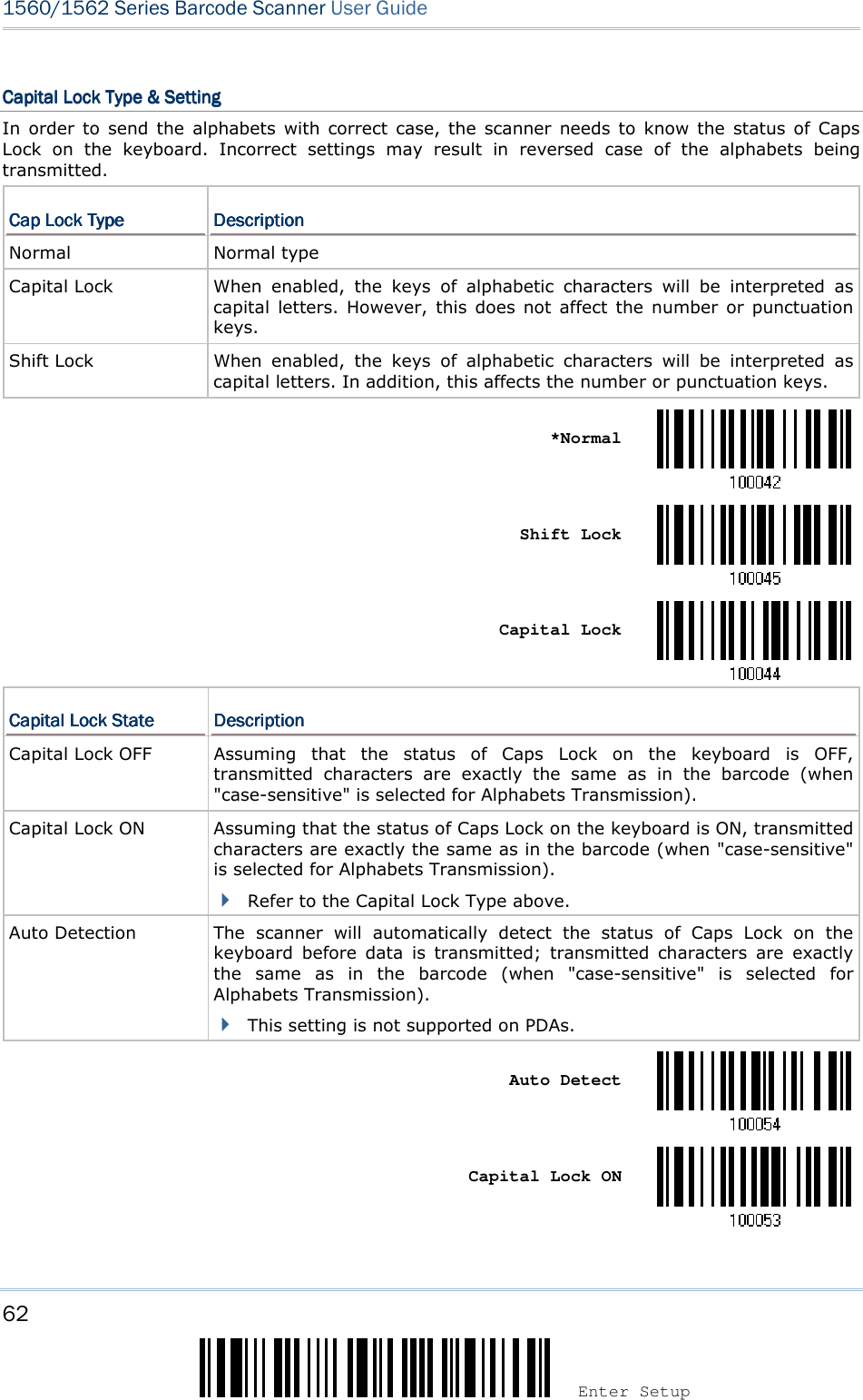
![63 Update Chapter 2 ! ! ! ! [[[[] ] ] ] Heading 1 Heading 1 Heading 1 Heading 1 *Capital Lock OFF](https://usermanual.wiki/CipherLab/3656CRADLE/User-Guide-3879656-Page-81.png)
![64 Enter Setup 1560/1562 Series Barcode Scanner User Guide Alphabets TransmissionAlphabets TransmissionAlphabets TransmissionAlphabets Transmission By default, the alphabets transmission is case-sensitive, meaning that the alphabets will be transmitted according to their original case, the status of Caps Lock on the keyboard, as well as the Capital Lock setting. Select [Ignore Case] to have alphabets transmitted according to the status of Caps Lock on the keyboard only. Ignore Case *Case-sensitive Refer to 5.1 Letter Case.](https://usermanual.wiki/CipherLab/3656CRADLE/User-Guide-3879656-Page-82.png)
![65 Update Chapter 2 ! ! ! ! [[[[] ] ] ] Heading 1 Heading 1 Heading 1 Heading 1 Digits TransmissionDigits TransmissionDigits TransmissionDigits Transmission By default, the alphanumeric keypad is used for transmitting digits. Select “Numeric Keypad” if you wish to use the keys on the numeric keypad. Numeric Key *Alphanumeric Key Note: If you select “Numeric Keypad”, the Num Lock status of the physical keyboard should be “ON”. This setting is not supported on PDAs.](https://usermanual.wiki/CipherLab/3656CRADLE/User-Guide-3879656-Page-83.png)
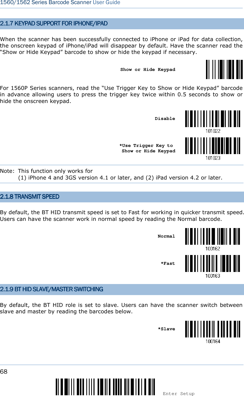
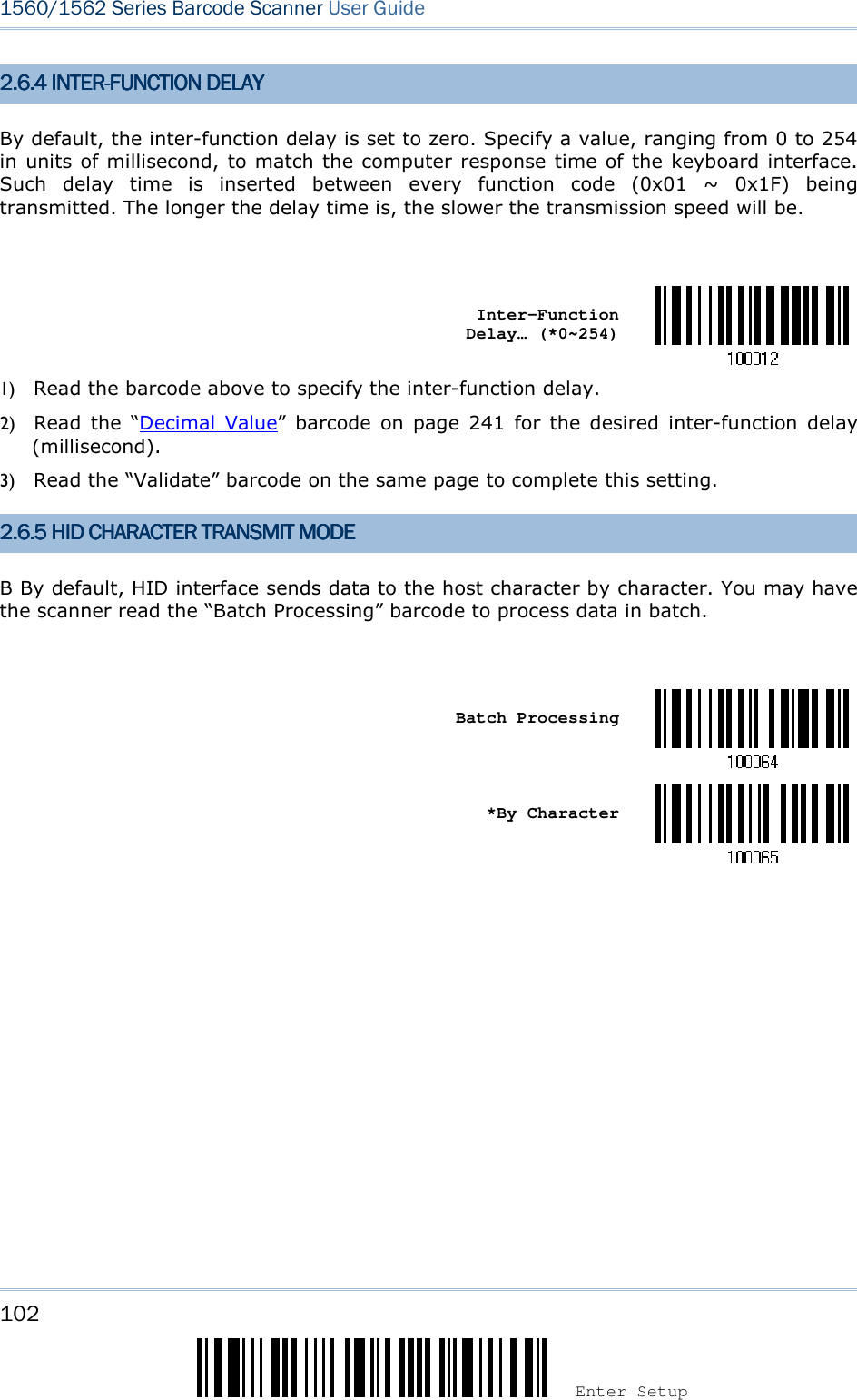
![67 Update Chapter 2 ! ! ! ! [[[[] ] ] ] Heading 1 Heading 1 Heading 1 Heading 1 2.2.2.2.1.1.1.1.6666 HID CHARACTER TRANSMHID CHARACTER TRANSMHID CHARACTER TRANSMHID CHARACTER TRANSMIT MODEIT MODEIT MODEIT MODE By default, HID interface sends data to the host character by character. You may have the scanner read the “Batch Processing” barcode to process data in batch. Batch Processing *By Character Note: “By Character” transmit mode is required when working with iPhone or iPad.](https://usermanual.wiki/CipherLab/3656CRADLE/User-Guide-3879656-Page-85.png)
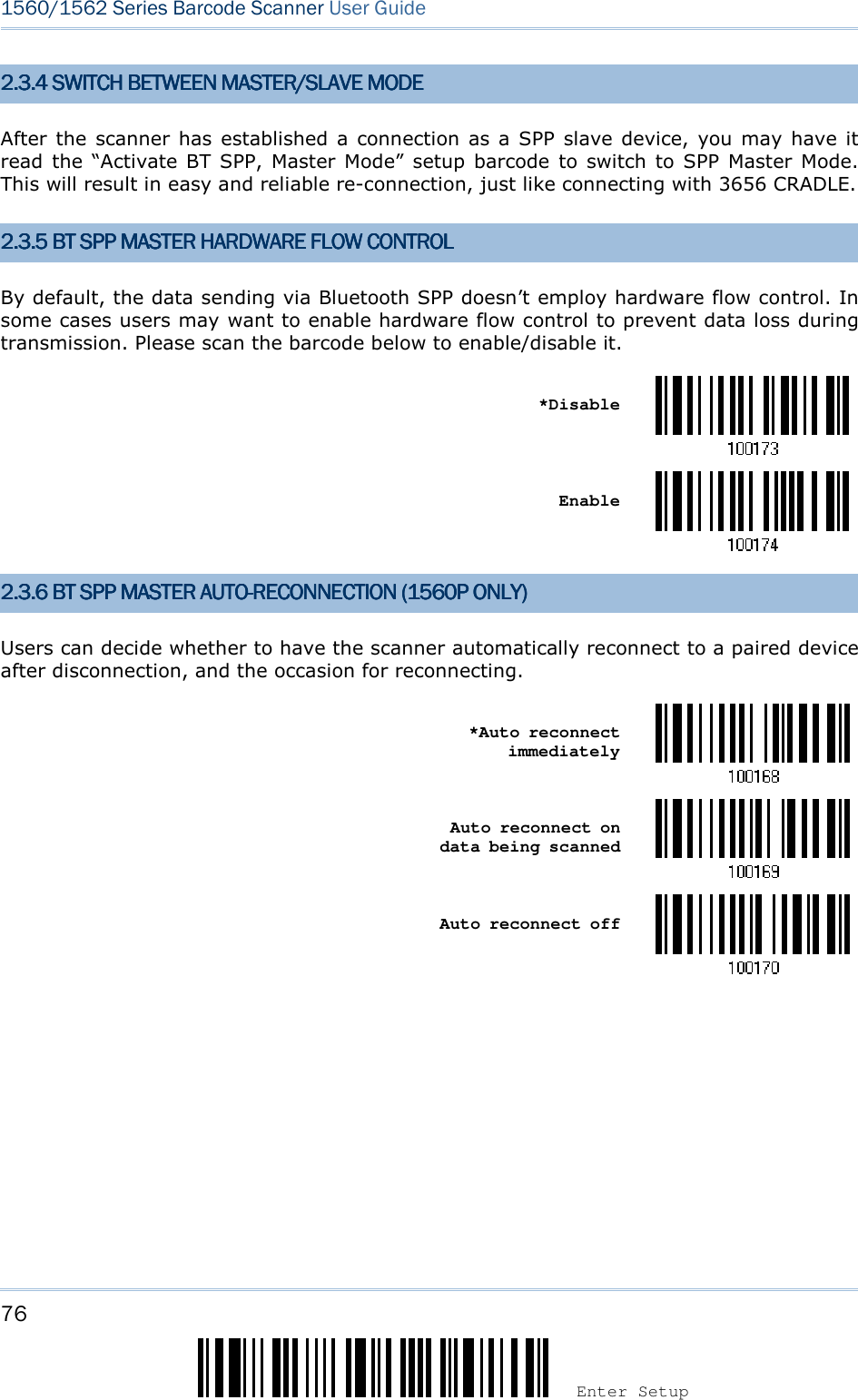
![69 Update Chapter 2 ! ! ! ! [[[[] ] ] ] Heading 1 Heading 1 Heading 1 Heading 1 Master 2.1.10 BT HID AUTO2.1.10 BT HID AUTO2.1.10 BT HID AUTO2.1.10 BT HID AUTO----RECONNECTION (1560P RECONNECTION (1560P RECONNECTION (1560P RECONNECTION (1560P ONLY)ONLY)ONLY)ONLY) Users can decide whether to have the scanner automatically reconnect to a paired device after disconnection, and the occasion for reconnecting. *Auto reconnect immediately Auto reconnect on data being scanned Auto reconnect off](https://usermanual.wiki/CipherLab/3656CRADLE/User-Guide-3879656-Page-87.png)
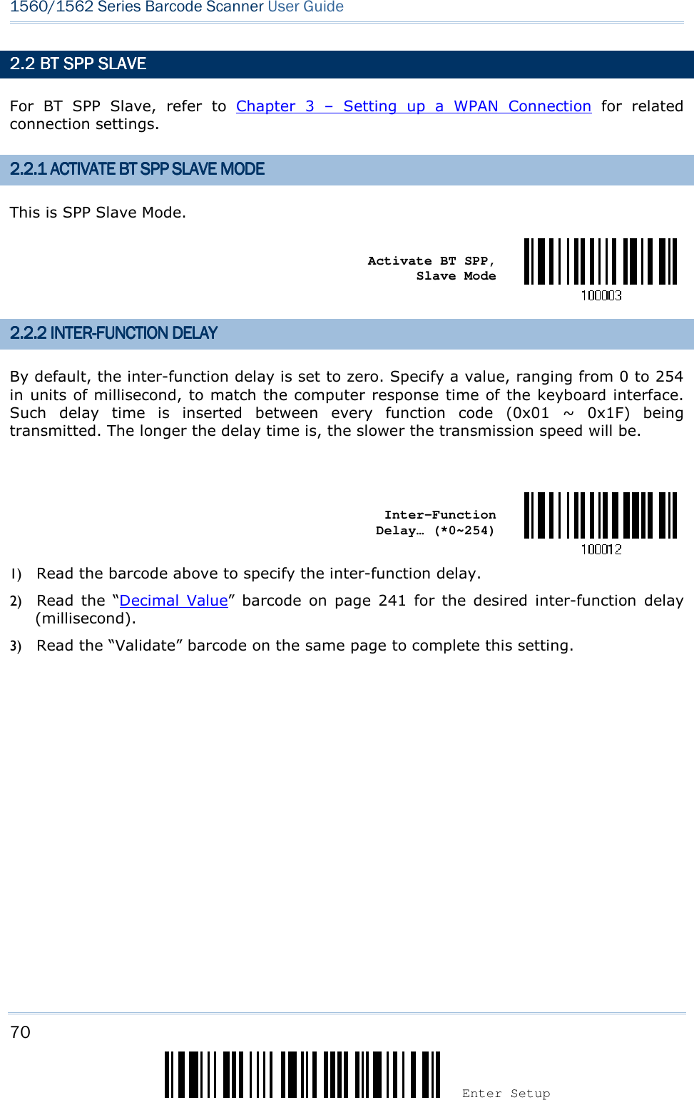
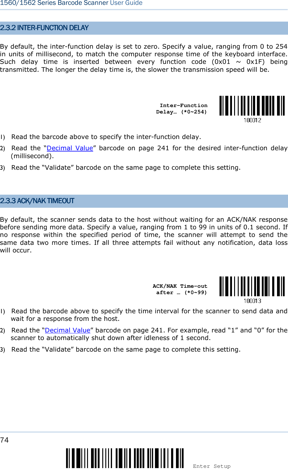
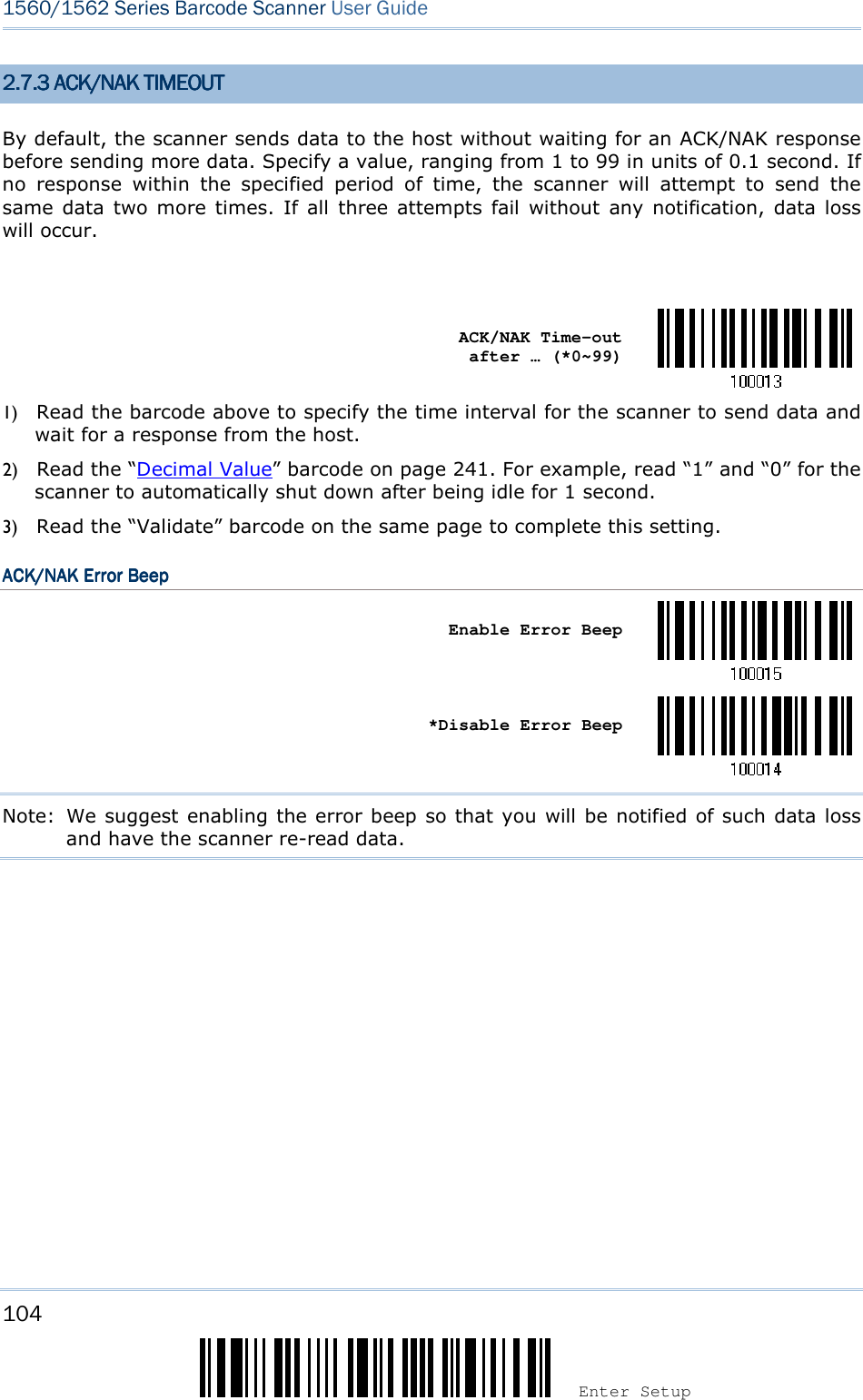
![71 Update Chapter 2 ! ! ! ! [[[[] ] ] ] Heading 1 Heading 1 Heading 1 Heading 1 2.2.2.2.2222.3.3.3.3 ACK/NAK TIACK/NAK TIACK/NAK TIACK/NAK TIMEOUTMEOUTMEOUTMEOUT By default, the scanner sends data to the host without waiting for an ACK/NAK response before sending more data. Specify a value, ranging from 1 to 99 in units of 0.1 second. If no response within the specified period of time, the scanner will attempt to send the same data two more times. If all three attempts fail without any notification, data loss will occur. ACK/NAK Time-out after … (*0~99) 1) Read the barcode above to specify the time interval for the scanner to send data and wait for a response from the host. 2) Read the “Decimal Value” barcode on page 241. For example, read “1” and “0” for the scanner to automatically shut down after idleness of 1 second. 3) Read the “Validate” barcode on the same page to complete this setting. ACK/NAK Error BeepACK/NAK Error BeepACK/NAK Error BeepACK/NAK Error Beep Enable Error Beep *Disable Error Beep Note: We suggest enabling the error beep so that you will be notified of such data loss and have the scanner re-read data. 2.2.4 2.2.4 2.2.4 2.2.4 BT SPP SLAVE HARDWARBT SPP SLAVE HARDWARBT SPP SLAVE HARDWARBT SPP SLAVE HARDWARE FLOW CONTROLE FLOW CONTROLE FLOW CONTROLE FLOW CONTROL By default, the data sending via Bluetooth SPP doesn’t employ hardware flow control. In some cases users may want to enable hardware flow control to prevent data loss during transmission. Please scan the barcode below to enable/disable it. *Disable Enable](https://usermanual.wiki/CipherLab/3656CRADLE/User-Guide-3879656-Page-89.png)
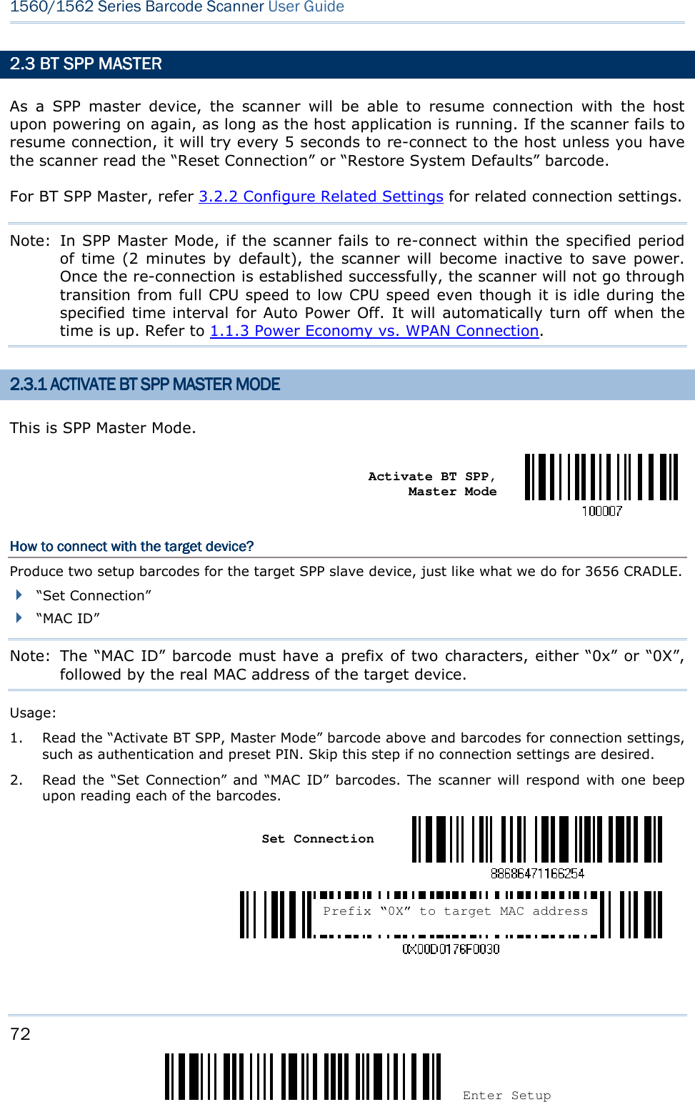
![73 Update Chapter 2 ! ! ! ! [[[[] ] ] ] Heading 1 Heading 1 Heading 1 Heading 1 Note: Read the “Set Connection” barcode first, and then the “MAC ID” barcode within 10 seconds. Instead of producing the “MAC ID” barcode, you may have the scanner read the setup barcodes for entering the MAC address. Have the scanner read the “Abort” barcode to cancel the operation at any time while reading setup barcodes for the MAC address. If the MAC address has not been completed yet, having the scanner read the “Validate” barcode can cancel the operation as well. Enter MAC ID in Hexadecimal… Usage: 1) Read the barcode above. 2) Read the “Hexadecimal System” barcode on page 242 for the desired MAC address. 3) Read the “Validate” barcode on the same page to complete this setting. CCCConnect with the target deviceonnect with the target deviceonnect with the target deviceonnect with the target device by scanning a single 1D setting barcodeby scanning a single 1D setting barcodeby scanning a single 1D setting barcodeby scanning a single 1D setting barcode Users can produce a single 1D setup barcode that combines the “Set Connection” and “MAC ID” setup commands to connect with the target device. While producing the barcode, be aware the letter upper/lower case “SeTcOn” and the barcode must be the Code 128 symbology. Usage: 1) Read the “Activate Bluetooth® SPP, Master Mode” barcode above and barcodes for connection settings, such as authentication and preset PIN. Skip this step if no connection settings are desired. 2) Read the “SeTcOnxxxxxxxxxxxx” 1D single barcode below. The scanner will respond with one beep upon reading the barcode. Exit SPP Master ModeExit SPP Master ModeExit SPP Master ModeExit SPP Master Mode To stop such re-connection, read “Reset Connection” or “Restore System Defaults” barcode so that the current connection record (= MAC ID) will be cleared. Then, the scanner will restart itself automatically. Go through the process in 3.2.3 Connect to Dongle to establish a new WPAN connection. Reset Connection](https://usermanual.wiki/CipherLab/3656CRADLE/User-Guide-3879656-Page-91.png)
![75 Update Chapter 2 ! ! ! ! [[[[] ] ] ] Heading 1 Heading 1 Heading 1 Heading 1 ACK/NAK Error BeepACK/NAK Error BeepACK/NAK Error BeepACK/NAK Error Beep Enable Error Beep *Disable Error Beep Note: We suggest enabling the error beep so that you will be notified of such data loss and have the scanner re-read data.](https://usermanual.wiki/CipherLab/3656CRADLE/User-Guide-3879656-Page-93.png)
![77 Update Chapter 2 ! ! ! ! [[[[] ] ] ] Heading 1 Heading 1 Heading 1 Heading 1 2222....4444 KEYBOARD WEDGEKEYBOARD WEDGEKEYBOARD WEDGEKEYBOARD WEDGE VIA VIA VIA VIA 3656365636563656 CRADLECRADLECRADLECRADLE The Y cable allows you to connect the scanner via 3656 CRADLE to the keyboard input port of PC and you may join the keyboard as well. The scanned data will be transmitted to the host keyboard port as if it is manually entered via the keyboard. For example, run a text editor on your computer to receive the data. Keyboard Wedge SettingsKeyboard Wedge SettingsKeyboard Wedge SettingsKeyboard Wedge Settings DefaultsDefaultsDefaultsDefaults Keyboard Type PCAT (US) Alphabets Layout Normal Digits Layout Normal Capital Lock Type Normal Capital Lock State Off Alphabets Transmission Case-sensitive Digits Transmission Alphanumeric keypad Alternate Composing No Laptop Support Disable Inter-Character Delay 0 (ms) Inter-Function Delay 0 (ms)](https://usermanual.wiki/CipherLab/3656CRADLE/User-Guide-3879656-Page-95.png)
![79 Update Chapter 2 ! ! ! ! [[[[] ] ] ] Heading 1 Heading 1 Heading 1 Heading 1 2.2.2.2.4444.2 KEYBOARD SETTINGS.2 KEYBOARD SETTINGS.2 KEYBOARD SETTINGS.2 KEYBOARD SETTINGS Alphabets Layout Digits Layout Capital Lock Type Capital Lock Setting Alphabets Transmission Digits Transmission Alternate Composing Laptop Support Alphabets LayoutAlphabets LayoutAlphabets LayoutAlphabets Layout By default, the alphabets layout is set to normal mode, also known as the standard English layout. Select French or German keyboard layout if necessary. The scanner will make adjustments when sending the "A", "Q", "W", "Z", "Y", and "M" characters according to this setting. *Normal AZERTY QWERTZ Note: This setting only works when the keyboard type selected is US keyboard, such as PCAT (US). The Alphabets Layout and Digits Layout setting must match your keyboard.](https://usermanual.wiki/CipherLab/3656CRADLE/User-Guide-3879656-Page-97.png)
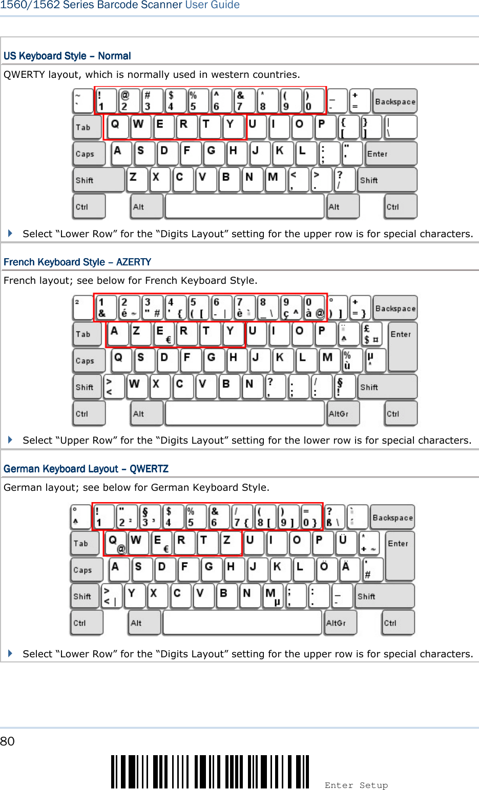
![81 Update Chapter 2 ! ! ! ! [[[[] ] ] ] Heading 1 Heading 1 Heading 1 Heading 1 Digits LayoutDigits LayoutDigits LayoutDigits Layout Select a proper layout that matches the alphabets layout. The scanner will make adjustments according to this setting.OptionsOptionsOptionsOptions DescriptionDescriptionDescriptionDescription Normal Depends on the [Shift] key or [Shift Lock] setting Lower Row For QWERTY or QWERTZ keyboard Upper Row For AZERTY keyboard *Normal Upper Row Lower Row Note: This setting is meant to be used with the Alphabets Layout; and perhaps with the Character Substitution setting when support to certain keyboard types (languages) is unavailable but required.](https://usermanual.wiki/CipherLab/3656CRADLE/User-Guide-3879656-Page-99.png)
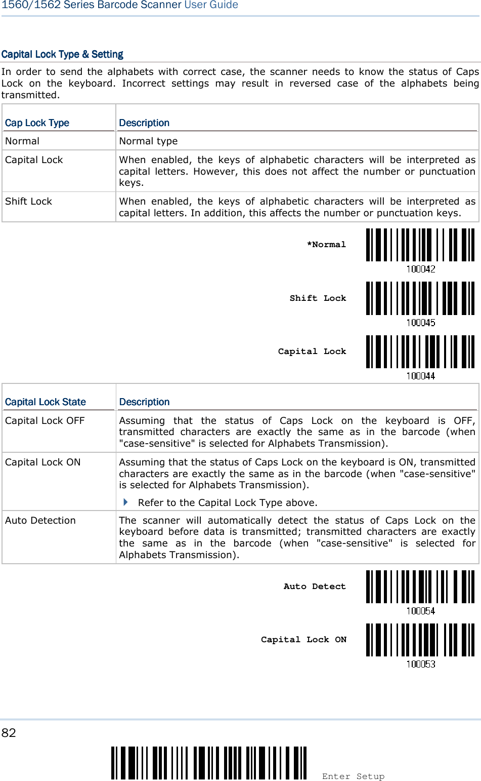
![83 Update Chapter 2 ! ! ! ! [[[[] ] ] ] Heading 1 Heading 1 Heading 1 Heading 1 *Capital Lock OFF](https://usermanual.wiki/CipherLab/3656CRADLE/User-Guide-3879656-Page-101.png)
![84 Enter Setup 1560/1562 Series Barcode Scanner User Guide Alphabets TransmissionAlphabets TransmissionAlphabets TransmissionAlphabets Transmission By default, the alphabets transmission is case-sensitive, meaning that the alphabets will be transmitted according to their original case, the status of Caps Lock on the keyboard, as well as the Capital Lock setting. Select [Ignore Case] to have alphabets transmitted according to the status of Caps Lock on the keyboard only. Ignore Case *Case-sensitive Refer to 5.1 Letter Case.](https://usermanual.wiki/CipherLab/3656CRADLE/User-Guide-3879656-Page-102.png)
![85 Update Chapter 2 ! ! ! ! [[[[] ] ] ] Heading 1 Heading 1 Heading 1 Heading 1 Digits TransmissionDigits TransmissionDigits TransmissionDigits Transmission By default, the alphanumeric keypad is used for transmitting digits. Select “Numeric Keypad” if you wish to use the keys on the numeric keypad. Numeric Key *Alphanumeric Key Note: If you select “Numeric Keypad”, the Num Lock status of the physical keyboard should be “ON”.](https://usermanual.wiki/CipherLab/3656CRADLE/User-Guide-3879656-Page-103.png)
![86 Enter Setup 1560/1562 Series Barcode Scanner User Guide ALT ComposingALT ComposingALT ComposingALT Composing By default, Alternate key composing is disabled. Select [Yes] to allow emulating Alternate key code of a specific keyboard character. For example, [Alt] + [065] will be sent to host for the character “A” regardless the keyboard type you are using. Yes *No Laptop SupportLaptop SupportLaptop SupportLaptop Support By default, laptop support is disabled. It is suggested to enable this feature if you connect the wedge cable to a laptop without an external keyboard being inter-connected. Enable *Disable](https://usermanual.wiki/CipherLab/3656CRADLE/User-Guide-3879656-Page-104.png)
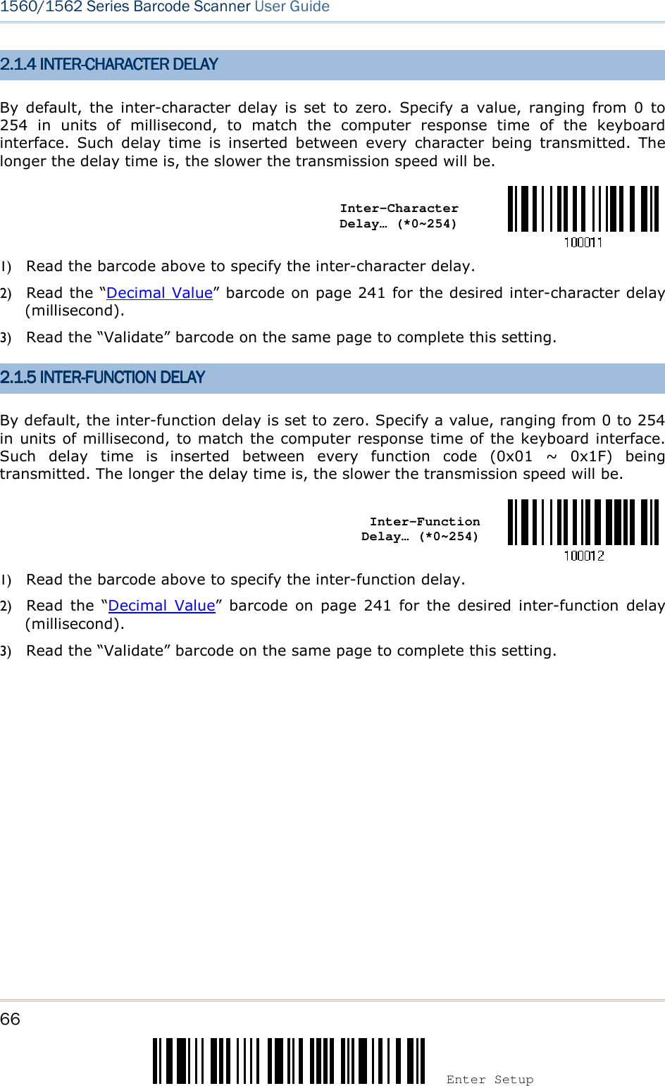
![87 Update Chapter 2 ! ! ! ! [[[[] ] ] ] Heading 1 Heading 1 Heading 1 Heading 1 2.2.2.2.4444.3 INTER.3 INTER.3 INTER.3 INTER----CHARACTER DELAYCHARACTER DELAYCHARACTER DELAYCHARACTER DELAY By default, the inter-character delay is set to zero. Specify a value, ranging from 0 to 254 in units of millisecond, to match the computer response time of the keyboard interface. Such delay time is inserted between every character being transmitted. The longer the delay time is, the slower the transmission speed will be. Inter-Character Delay… (*0~254) 1) Read the barcode above to specify the inter-character delay. 2) Read the “Decimal Value” barcode on page 241 for the desired inter-character delay (millisecond). 3) Read the “Validate” barcode on the same page to complete this setting. 2.2.2.2.4444.4 INTER.4 INTER.4 INTER.4 INTER----FUNCTION DELAYFUNCTION DELAYFUNCTION DELAYFUNCTION DELAY By default, the inter-function delay is set to zero. Specify a value, ranging from 0 to 254 in units of millisecond, to match the computer response time of the keyboard interface. Such delay time is inserted between every function code (0x01 ~ 0x1F) being transmitted. The longer the delay time is, the slower the transmission speed will be. Inter-Function Delay… (*0~254) 1) Read the barcode above to specify the inter-function delay. 2) Read the “Decimal Value” barcode on page 241 for the desired inter-function delay (millisecond). 3) Read the “Validate” barcode on the same page to complete this setting.](https://usermanual.wiki/CipherLab/3656CRADLE/User-Guide-3879656-Page-105.png)
![89 Update Chapter 2 ! ! ! ! [[[[] ] ] ] Heading 1 Heading 1 Heading 1 Heading 1 4800 bps 2400 bps 1200 bps 600 bps 2.2.2.2.5555.3 DATA BITS.3 DATA BITS.3 DATA BITS.3 DATA BITS *8 bits 7 bits 2.2.2.2.5555.4 PARITY.4 PARITY.4 PARITY.4 PARITY *No parity Even Odd](https://usermanual.wiki/CipherLab/3656CRADLE/User-Guide-3879656-Page-107.png)
![91 Update Chapter 2 ! ! ! ! [[[[] ] ] ] Heading 1 Heading 1 Heading 1 Heading 1 2.2.2.2.5555.7 INTER.7 INTER.7 INTER.7 INTER----CHARACTER DELAYCHARACTER DELAYCHARACTER DELAYCHARACTER DELAY By default, the inter-character delay is zero. Specify a value, ranging from 0 to 254 in units of millisecond, to match the computer response time. Such delay time is inserted between every character being transmitted. The longer the delay time is, the slower the transmission speed will be. Inter-Character Delay… (*0~254) 1) Read the barcode above to specify the inter-character delay. 2) Read the “Decimal Value” barcode on page 241 for the desired inter-character delay (millisecond). 3) Read the “Validate” barcode on the same page to complete this setting. 2.2.2.2.5555.8 INTER.8 INTER.8 INTER.8 INTER----FUNCTION DELAYFUNCTION DELAYFUNCTION DELAYFUNCTION DELAY By default, the inter-function delay is set to zero. Specify a value, ranging from 0 to 254 in units of millisecond, to match the computer response time of the keyboard interface. Such delay time is inserted between every function code (0x01 ~ 0x1F) being transmitted. The longer the delay time is, the slower the transmission speed will be. Inter-Function Delay… (*0~254) 1) Read this barcode above to specify the inter-function delay. 2) Read the “Decimal Value” barcode on page 241 for the desired inter-function delay (millisecond). 3) Read the “Validate” barcode on the same page to complete this setting.](https://usermanual.wiki/CipherLab/3656CRADLE/User-Guide-3879656-Page-109.png)

![93 Update Chapter 2 ! ! ! ! [[[[] ] ] ] Heading 1 Heading 1 Heading 1 Heading 1 2.2.2.2.6666 USB HID VIA USB HID VIA USB HID VIA USB HID VIA 3656365636563656 CRADLECRADLECRADLECRADLE For USB HID, use the USB cable to connect the scanner via 3656 CRADLE to the USB port of PC and connect the power supply cord. Run any text editor on your computer, and the scanned data will be transmitted to the computer. Warning: When the 3656 CRADLE stand is solely on USB power, the current may be insufficient for it to function normally. You must connect the power supply cord. HID SettingsHID SettingsHID SettingsHID Settings DefaultsDefaultsDefaultsDefaults Keyboard Type PCAT (US) Digits Layout Normal Capital Lock Type Normal Capital Lock State Off Alphabets Transmission Case-sensitive Digits Transmission Alphanumeric keypad Inter-Character Delay 0 (ms) Inter-Function Delay 0 (ms)](https://usermanual.wiki/CipherLab/3656CRADLE/User-Guide-3879656-Page-111.png)
![95 Update Chapter 2 ! ! ! ! [[[[] ] ] ] Heading 1 Heading 1 Heading 1 Heading 1 2.2.2.2.6666....2222 KEYBOARD SETTINGSKEYBOARD SETTINGSKEYBOARD SETTINGSKEYBOARD SETTINGS Alphabets Layout Digits Layout Capital Lock Type Capital Lock Setting Alphabets Transmission Digits Transmission Alphabets LayoutAlphabets LayoutAlphabets LayoutAlphabets Layout By default, the alphabets layout is set to normal mode, also known as the standard English layout. Select French or German keyboard layout if necessary. The scanner will make adjustments when sending the "A", "Q", "W", "Z", "Y", and "M" characters according to this setting. *Normal AZERTY QWERTZ Note: This setting only works when the keyboard type selected is US keyboard, such as PCAT (US). The Alphabets Layout and Digits Layout setting must match your keyboard.](https://usermanual.wiki/CipherLab/3656CRADLE/User-Guide-3879656-Page-113.png)

![97 Update Chapter 2 ! ! ! ! [[[[] ] ] ] Heading 1 Heading 1 Heading 1 Heading 1 Digits LayoutDigits LayoutDigits LayoutDigits Layout Select a proper layout that matches the alphabets layout. The scanner will make adjustments according to this setting.OptionsOptionsOptionsOptions DescriptionDescriptionDescriptionDescription Normal Depends on the [Shift] key or [Shift Lock] setting Lower Row For QWERTY or QWERTZ keyboard Upper Row For AZERTY keyboard *Normal Upper Row Lower Row Note: This setting is to be used with the Character Substitution setting when support to certain keyboard types (languages) is unavailable but required.](https://usermanual.wiki/CipherLab/3656CRADLE/User-Guide-3879656-Page-115.png)

![99 Update Chapter 2 ! ! ! ! [[[[] ] ] ] Heading 1 Heading 1 Heading 1 Heading 1 *Capital Lock OFF](https://usermanual.wiki/CipherLab/3656CRADLE/User-Guide-3879656-Page-117.png)
![100 Enter Setup 1560/1562 Series Barcode Scanner User Guide Alphabets TransmissionAlphabets TransmissionAlphabets TransmissionAlphabets Transmission By default, the alphabets transmission is case-sensitive, meaning that the alphabets will be transmitted according to their original case, the status of Caps Lock on the keyboard, as well as the Capital Lock setting. Select [Ignore Case] to have alphabets transmitted according to the status of Caps Lock on the keyboard only. Ignore Case *Case-sensitive Refer to 5.1 Letter Case.](https://usermanual.wiki/CipherLab/3656CRADLE/User-Guide-3879656-Page-118.png)
![101 Update Chapter 2 ! ! ! ! [[[[] ] ] ] Heading 1 Heading 1 Heading 1 Heading 1 Digits TransmissDigits TransmissDigits TransmissDigits Transmissionionionion By default, the alphanumeric keypad is used for transmitting digits. Select “Numeric Keypad” if you wish to use the keys on the numeric keypad. Numeric Key *Alphanumeric Key Note: If you select “Numeric Keypad”, the Num Lock status of the physical keyboard should be "ON". 2.6.3 INTER2.6.3 INTER2.6.3 INTER2.6.3 INTER----CHARACTER DELAYCHARACTER DELAYCHARACTER DELAYCHARACTER DELAY By default, the inter-character delay is set to zero. Specify a value, ranging from 0 to 254 in units of millisecond, to match the computer response time of the keyboard interface. Such delay time is inserted between every character being transmitted. The longer the delay time is, the slower the transmission speed will be. Inter-Character Delay… (*0~254) 1) Read the barcode above to specify the inter-character delay. 2) Read the “Decimal Value” barcode on page 241 for the desired inter-character delay (millisecond). 3) Read the “Validate” barcode on the same page to complete this setting.](https://usermanual.wiki/CipherLab/3656CRADLE/User-Guide-3879656-Page-119.png)
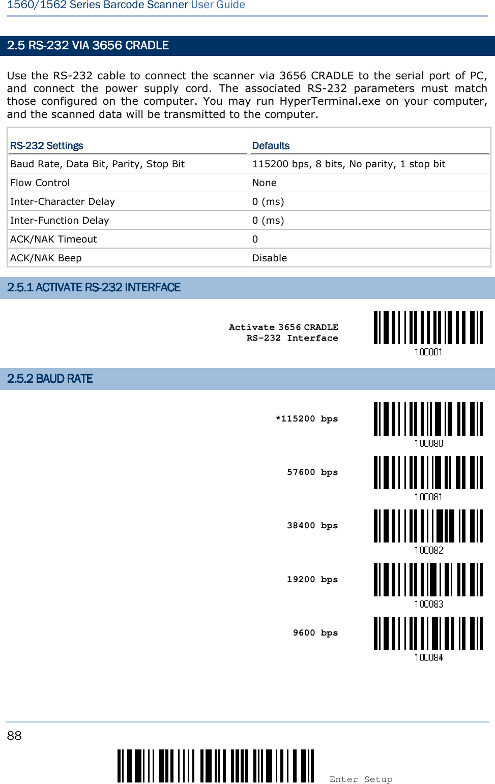
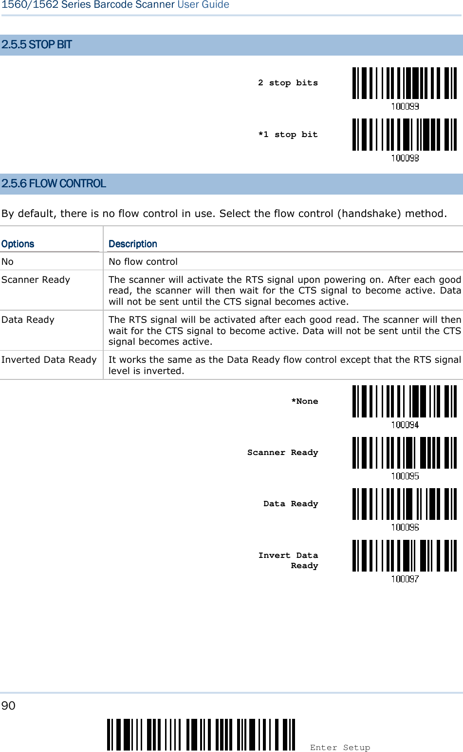
![103 Update Chapter 2 ! ! ! ! [[[[] ] ] ] Heading 1 Heading 1 Heading 1 Heading 1 2.2.2.2.7777 USB VIRTUAL COM VIA USB VIRTUAL COM VIA USB VIRTUAL COM VIA USB VIRTUAL COM VIA 3656365636563656 CRADLECRADLECRADLECRADLE Use the USB cable to connect the scanner via 3656 CRADLE to the USB port of PC and connect the power supply cord. You may run HyperTerminal.exe on your computer, and the scanned data will be transmitted to the computer. Warning: When the 3656 CRADLE stand is solely on USB power, the current may be insufficient for it to function normally. You must connect the power supply cord. Note: If using USB Virtual COM for the first time, you must install its driver beforehand. Driver version 5.4 or later is required. Please remove older versions! 2.2.2.2.7777.1 ACTIVATE .1 ACTIVATE .1 ACTIVATE .1 ACTIVATE USB VIRTUAL COMUSB VIRTUAL COMUSB VIRTUAL COMUSB VIRTUAL COM Activate 3656 CRADLE USB Virtual COM 2.2.2.2.7777.2 INTER.2 INTER.2 INTER.2 INTER----FUNCTION DELAYFUNCTION DELAYFUNCTION DELAYFUNCTION DELAY By default, the inter-function delay is set to zero. Specify a value, ranging from 0 to 254 in units of millisecond, to match the computer response time of the keyboard interface. Such delay time is inserted between every function code (0x01 ~ 0x1F) being transmitted. The longer the delay time is, the slower the transmission speed will be. Inter-Function Delay… (*0~254) 1) Read the barcode above to specify the inter-function delay. 2) Read the “Decimal Value” barcode on page 241 for the desired inter-function delay (millisecond). 3) Read the “Validate” barcode on the same page to complete this setting.](https://usermanual.wiki/CipherLab/3656CRADLE/User-Guide-3879656-Page-121.png)
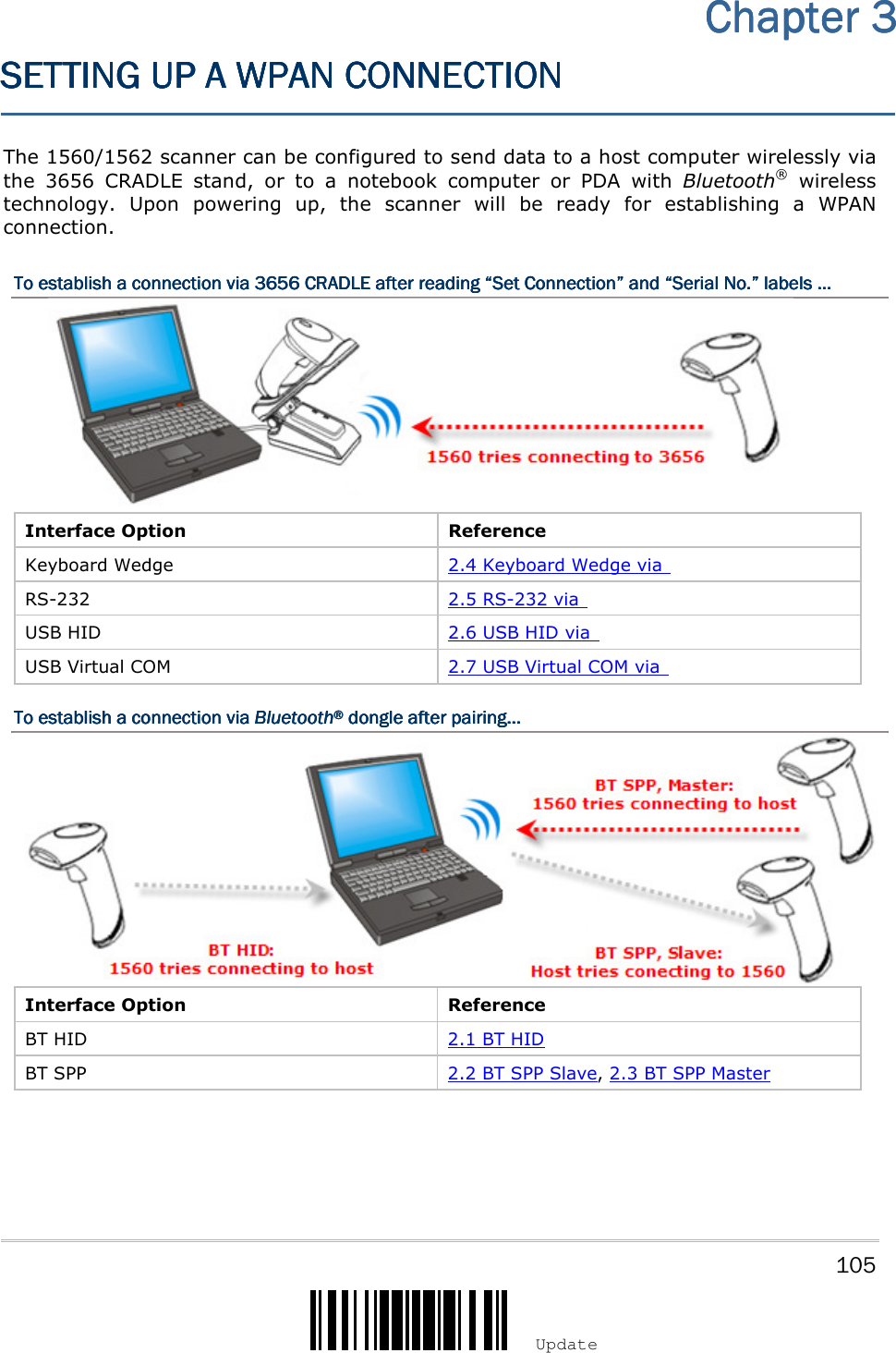
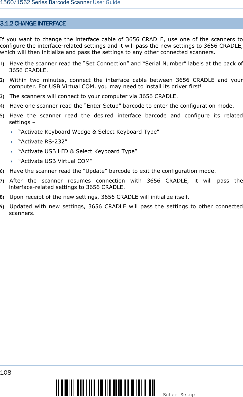
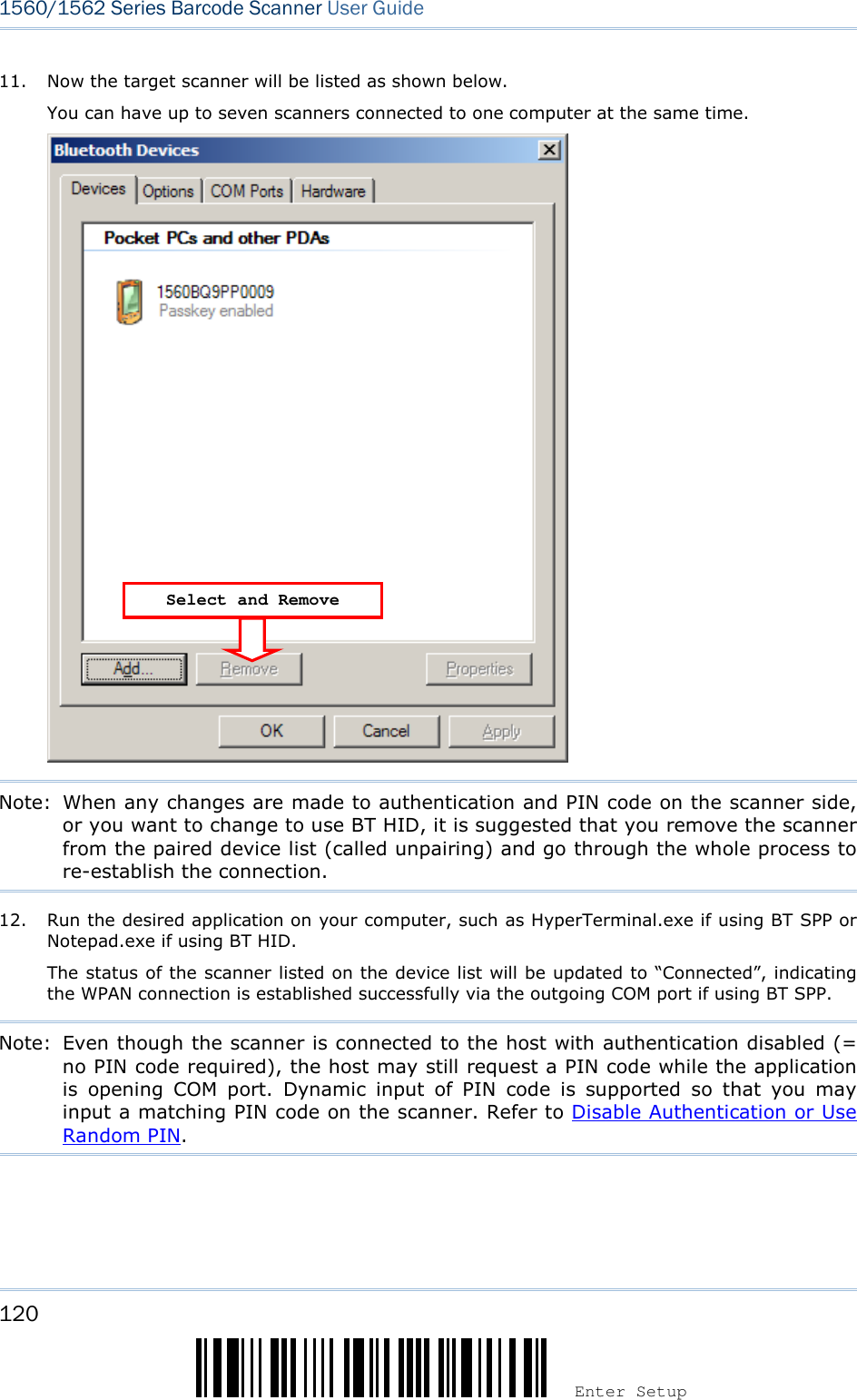
![107 Update Chapter 3 ! ! ! ! [[[[] ] ] ] Heading 1 Heading 1 Heading 1 Heading 1 3.3.3.3.1111 CONNECTING VIA CONNECTING VIA CONNECTING VIA CONNECTING VIA 3656365636563656 CRADLECRADLECRADLECRADLE By default, the interface of 3656 CRADLE is set to “USB HID”. Use the interface cable to connect the scanner via 3656 CRADLE to PC. You can have up to seven scanners connected to one computer at the same time. Note: If using USB Virtual COM for the first time, you must install its driver beforehand. Driver version 5.4 or later is required. Please remove older versions! 3.3.3.3.1111.1 CONNECT TO .1 CONNECT TO .1 CONNECT TO .1 CONNECT TO 3656365636563656 CRADLECRADLECRADLECRADLE By scanning two setting barcodes in sequenceBy scanning two setting barcodes in sequenceBy scanning two setting barcodes in sequenceBy scanning two setting barcodes in sequence Connect any scanner to 3656 CRADLE by reading the two labels at the back of 3656 CRADLE. The scanner will respond with one beep upon reading each of the labels. “Set Connection” label “Serial Number” label After reading these labels, the scanner will stay active for a specified period of time (2 minutes by default) trying to connect to the 3656 CRADLE while its LED is flashing blue (On/Off ratio 0.5 s: 0.5 s). Once connected, the scanner will respond with three beeps (tone ascending from low to high), and the LED flashes blue (On/Off ratio 0.02 s: 3 s). When out of range, the scanner will respond with three short beeps (tone descending from high to low). Usage: Read the “Set Connection” barcode first, and then the “Serial Number” barcode. If the “Set Connection” barcode on 3656 CRADLE is illegible, try this one — Set Connection Note: The 3656 CRADLE settings will overwrite the interface-related settings on the scanners that are currently connected to 3656 CRADLE. By scanning a single 1D setting barcodeBy scanning a single 1D setting barcodeBy scanning a single 1D setting barcodeBy scanning a single 1D setting barcode Users can produce a single 1D setup barcode that combines the “Set Connection” and “3656 CRADLE Serial Number” setup commands to connect with the target device. While producing the barcode, be aware the letter upper/lower case “SeTcOn” and the barcode must be the Code 128 symbology. Usage: Read the “SeTcOnxxxxxxxxx” single 1D barcode. The scanner will respond with one beep upon reading the barcode.](https://usermanual.wiki/CipherLab/3656CRADLE/User-Guide-3879656-Page-125.png)
![109 Update Chapter 3 ! ! ! ! [[[[] ] ] ] Heading 1 Heading 1 Heading 1 Heading 1](https://usermanual.wiki/CipherLab/3656CRADLE/User-Guide-3879656-Page-127.png)
![111 Update Chapter 3 ! ! ! ! [[[[] ] ] ] Heading 1 Heading 1 Heading 1 Heading 1 3.3.3.3.2222 CONNECTING VIA CONNECTING VIA CONNECTING VIA CONNECTING VIA BLUETOOTHBLUETOOTHBLUETOOTHBLUETOOTH®®®® DONGLEDONGLEDONGLEDONGLE 3.3.3.3.2222.1 C.1 C.1 C.1 CHANGEHANGEHANGEHANGE INTERFACEINTERFACEINTERFACEINTERFACE Below is the procedure to configure the scanner before establishing a WPAN connection via Bluetooth® dongle. 1) Have the scanner read the “Enter Setup” barcode to enter the configuration mode. 2) Have the scanner read the desired interface barcode – “Activate BT HID & Select Keyboard Type” “Activate BT SPP Slave Mode” “Activate BT SPP Master Mode” 3) Have the scanner read the barcodes related to WPAN settings, such as Device Name Broadcasting, Authentication & PIN Code, etc. 4) Have the scanner read the “Update” barcode to exit the configuration mode. 5) The scanner will stay active for a specified period of time (2 minutes by default) waiting for a connection request from the host (SPP Slave Mode) or trying to connect to the host (HID or SPP Master Mode). Its CPU is running at full speed, and the LED is flashing blue (On/Off ratio 0.5 s: 0.5 s). Once connected, when getting out of range, the scanner will respond with three short beeps (tone descending from high to low).](https://usermanual.wiki/CipherLab/3656CRADLE/User-Guide-3879656-Page-129.png)
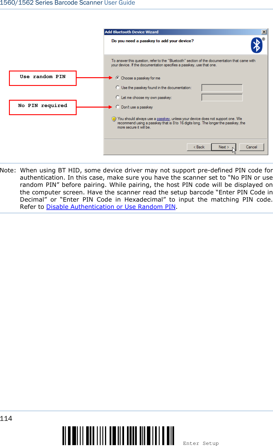
![113 Update Chapter 3 ! ! ! ! [[[[] ] ] ] Heading 1 Heading 1 Heading 1 Heading 1 AuthenticationAuthenticationAuthenticationAuthentication When any changes are made to authentication and PIN code on the scanner side, you will have to remove the scanner from the paired device list (called unpairing) and go through the whole process to re-establish the connection. The scanner allows up to 16 characters for a PIN code and provides two options for authentication: Enable Enable Enable Enable AuthenticationAuthenticationAuthenticationAuthentication with Preset PINwith Preset PINwith Preset PINwith Preset PIN Have the scanner read the “Use preset PIN” barcode, and change the preset PIN if necessary. This means you will have to enter exactly the same string for your computer or PDA to connect to the scanner. If the PIN or passkey is incorrect, any connection attempt will be turned down by the scanner. See step 8 in 3.2.3 Connect to Dongle. 1. Read the “Use preset PIN” barcode to enable authentication with a preset PIN. Use Preset PIN 2. Read one of the barcodes to specify the PIN code, in decimal or hexadecimal. By default, the PIN code is set to “0000”. Maximum 16 characters are allowed. Enter PIN in Hexadecimal … Enter PIN in Decimal… 3. Read the “Decimal Value” barcode on page 241 or the “Hexadecimal Value” barcode on page 242 for the desired digits or character string. Read the “Clear PIN Code” barcode first if you need to re-input the PIN code. Clear PIN Code 4. Read the “Validate” barcode to complete this setting. Enable Enable Enable Enable AuthenticationAuthenticationAuthenticationAuthentication with Random PIN or No Authenticationwith Random PIN or No Authenticationwith Random PIN or No Authenticationwith Random PIN or No Authentication By default, it is set to “No PIN or use random PIN”, which depends on the setting of the target device. (No PIN = No authentication.) *No PIN or use random PIN](https://usermanual.wiki/CipherLab/3656CRADLE/User-Guide-3879656-Page-131.png)
![115 Update Chapter 3 ! ! ! ! [[[[] ] ] ] Heading 1 Heading 1 Heading 1 Heading 1 3.2.3.2.3.2.3.2.3333 CONNECT TO DONGLECONNECT TO DONGLECONNECT TO DONGLECONNECT TO DONGLE The procedure goes through associating devices for establishing a WPAN connection, which is pretty much the same except for the software you are using. If your computer is running Microsoft® Windows® XP Service Pack 3 (SP3) or Windows Vista® Service Pack 1 (SP1), you can use the software support that Windows® includes, or you can use the driver that the device manufacturer provides. Now, let’s try using the software support that Windows® XP Service Pack 2 includes. BT HID ProcedureBT HID ProcedureBT HID ProcedureBT HID Procedure By default, BT HID is activated on the scanner, and the keyboard type is set to PCAT (US). When BT HID is re-activated, you will have to select a keyboard type to complete this setting. The procedure is the same as for BT SPP. Refer to steps 1~11 below. BT BT BT BT SPPSPPSPPSPP ProcedureProcedureProcedureProcedure 1. Turn on the Bluetooth® function on your computer, running Windows XP SP2. 2. Double-click the Bluetooth® icon from the lower right of the taskbar. Alternatively, you may go to Control Panel > Bluetooth Devices. 3. Click [Add] to search devices nearby.](https://usermanual.wiki/CipherLab/3656CRADLE/User-Guide-3879656-Page-133.png)
![116 Enter Setup 1560/1562 Series Barcode Scanner User Guide 4. Turn on the scanner with correct WPAN settings, such as select BT SPP or BT HID, broadcasting enabled, authentication enabled, and PIN code specified, etc. Select the check box of [My device is set up and ready to be found] on your computer. 5. Click [Next]. 6. Wait for a few seconds for the Wizard to search available devices nearby. The scanner will appear with its “serial number” as the device name. You may double-check the “Serial Number” label on the scanner to ensure connecting with the correct scanner. Select the target scanner. If the target scanner does not appear on the list, click [Search Again] to refresh the list. The scanner might enter Suspend Mode now, and you can press the trigger to have it active again (=discoverable). It will then stay active for a specified period of time (2 minutes by default) and wait for PC to establish a connection.](https://usermanual.wiki/CipherLab/3656CRADLE/User-Guide-3879656-Page-134.png)
![117 Update Chapter 3 ! ! ! ! [[[[] ] ] ] Heading 1 Heading 1 Heading 1 Heading 1 7. Click [Next]. 8. Enter the passkey for authentication, which must be exactly the same as configured for the scanner.](https://usermanual.wiki/CipherLab/3656CRADLE/User-Guide-3879656-Page-135.png)
![118 Enter Setup 1560/1562 Series Barcode Scanner User Guide 9. Click [Next]. Wait for a few seconds for Windows to exchange passkeys.](https://usermanual.wiki/CipherLab/3656CRADLE/User-Guide-3879656-Page-136.png)
![119 Update Chapter 3 ! ! ! ! [[[[] ] ] ] Heading 1 Heading 1 Heading 1 Heading 1 Note: When Bluetooth security is enabled without providing a pre-set PIN code, dynamic input of PIN code is supported. 10. Click [Finish]. 1560 as BT SPP Slave 1560 as BT SPP Master](https://usermanual.wiki/CipherLab/3656CRADLE/User-Guide-3879656-Page-137.png)
![121 Update Chapter 3 ! ! ! ! [[[[] ] ] ] Heading 1 Heading 1 Heading 1 Heading 1 BT SPP Connected BT SPP Disconnected](https://usermanual.wiki/CipherLab/3656CRADLE/User-Guide-3879656-Page-139.png)
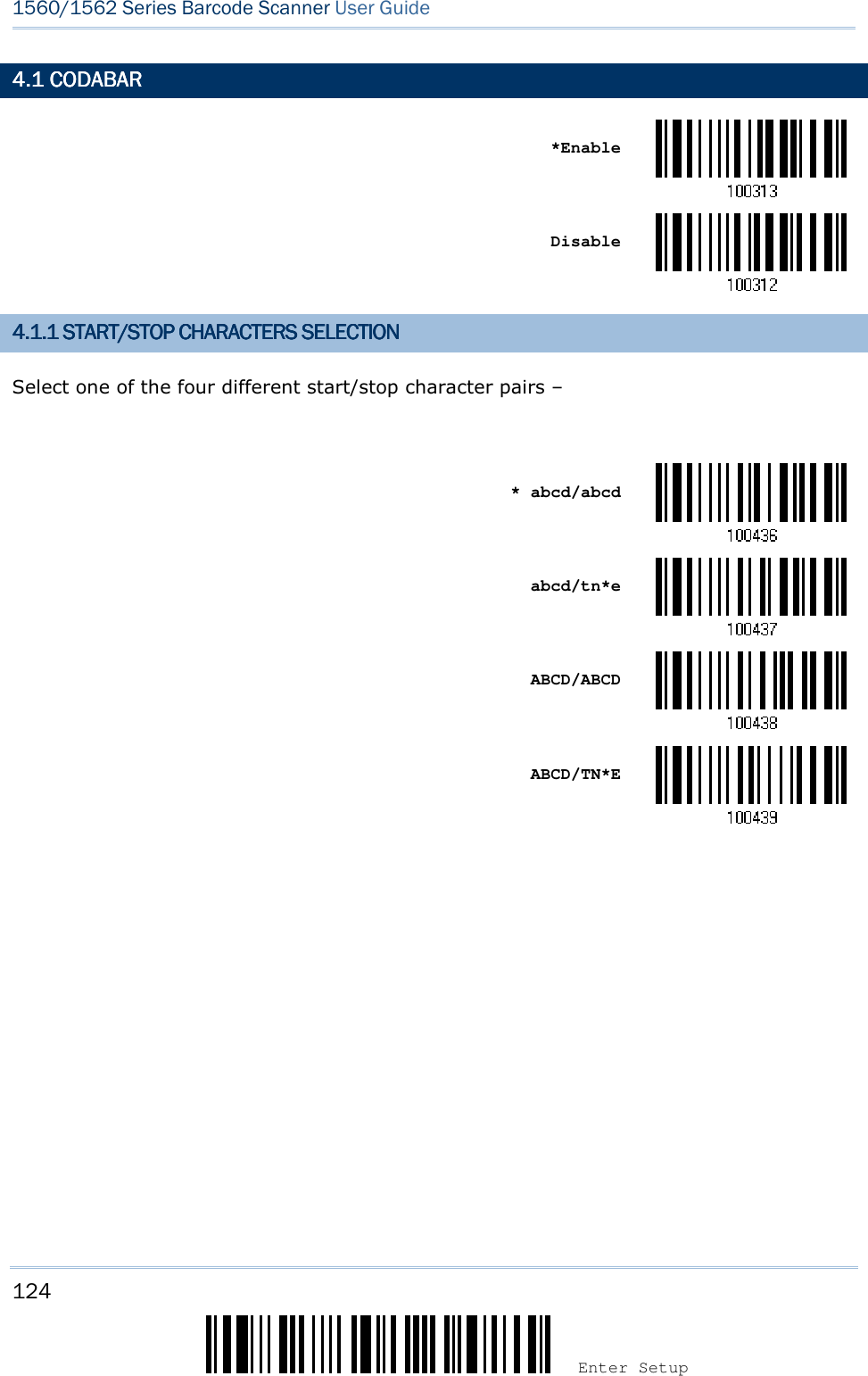
![125 Update Chapter 4 !!!! [[[[] ] ] ] Heading 1 Heading 1 Heading 1 Heading 1 4.1.2 START/STOP TRA4.1.2 START/STOP TRA4.1.2 START/STOP TRA4.1.2 START/STOP TRANSMISSIONNSMISSIONNSMISSIONNSMISSION Decide whether to include the start/stop characters in the data being transmitted. Transmit Start/Stop Characters *Do Not Transmit 4.1.3 CLSI CONVERSIO4.1.3 CLSI CONVERSIO4.1.3 CLSI CONVERSIO4.1.3 CLSI CONVERSIONNNN When enabled, the CLSI editing strips the start/stop characters and inserts a space after the first, fifth, and tenth characters of a 14-character Codabar barcode. Apply CLSI Editing *Do Not Apply Note: The 14-character barcode length does not include start/stop characters. 4.1.4 SECUR4.1.4 SECUR4.1.4 SECUR4.1.4 SECURITY LEVELITY LEVELITY LEVELITY LEVEL Security Level renders more decoding accuracy giving consideration to barcodes’ print quality. Decide the security level for reading CodaBar barcodes. Normal *High](https://usermanual.wiki/CipherLab/3656CRADLE/User-Guide-3879656-Page-143.png)
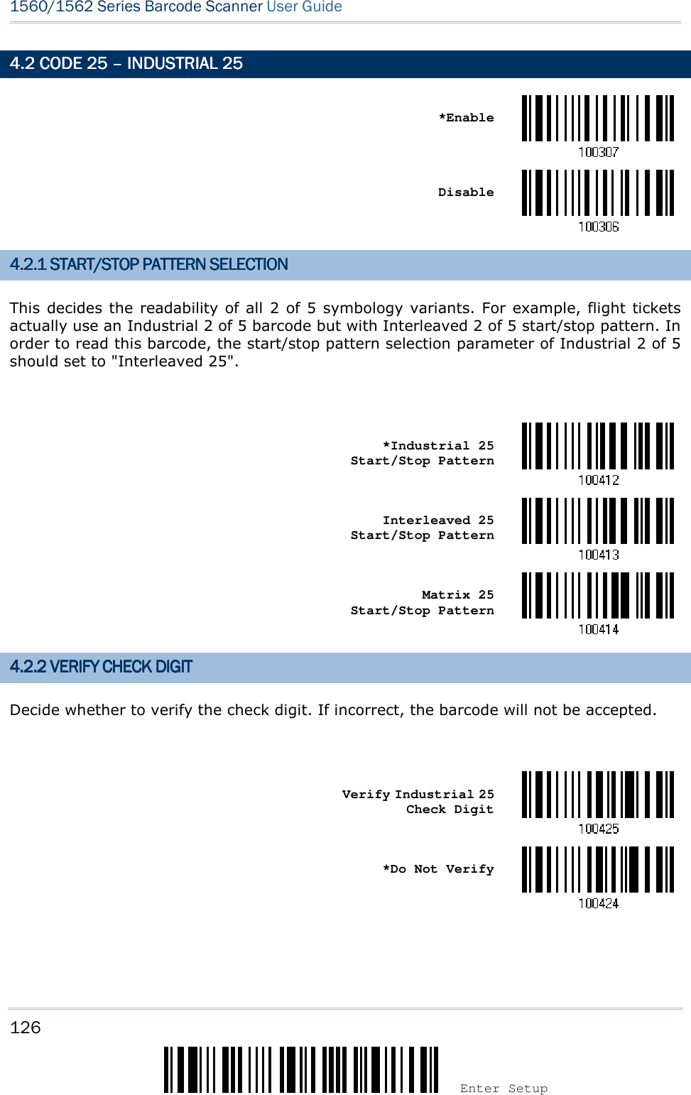
![127 Update Chapter 4 ! ! ! ! [[[[] ] ] ] Heading 1 Heading 1 Heading 1 Heading 1 4.2.3 4.2.3 4.2.3 4.2.3 TRANSMIT CHECK DIGITTRANSMIT CHECK DIGITTRANSMIT CHECK DIGITTRANSMIT CHECK DIGIT Decide whether to include the check digit in the data being transmitted. *Transmit Industrial 25 Check Digit Do Not Transmit 4.2.4 CODE LENGTH QU4.2.4 CODE LENGTH QU4.2.4 CODE LENGTH QU4.2.4 CODE LENGTH QUALIFICATIONALIFICATIONALIFICATIONALIFICATION To prevent the "short scan" error, define the "Length Qualification" settings to ensure that the correct barcode is read by qualifying the allowable code length. If "Max/Min Length" is selected, the maximum length and the minimum length must be specified. It only accepts those barcodes with lengths that fall between max/min lengths specified. If “Fixed Length” is selected, up to 2 fixed lengths can be specified. 1) Read the barcode to enable either Max. /Min. Length qualification or Fixed Length(s) qualification. *Enable Max./Min. Length (0~127)… Enable Fixed Length(s)… 2) Read the barcode for Max. Length or Fixed Length 1, and follow steps 3~4. Repeat steps 2~4 for Min. Length or Fixed Length 2.](https://usermanual.wiki/CipherLab/3656CRADLE/User-Guide-3879656-Page-145.png)
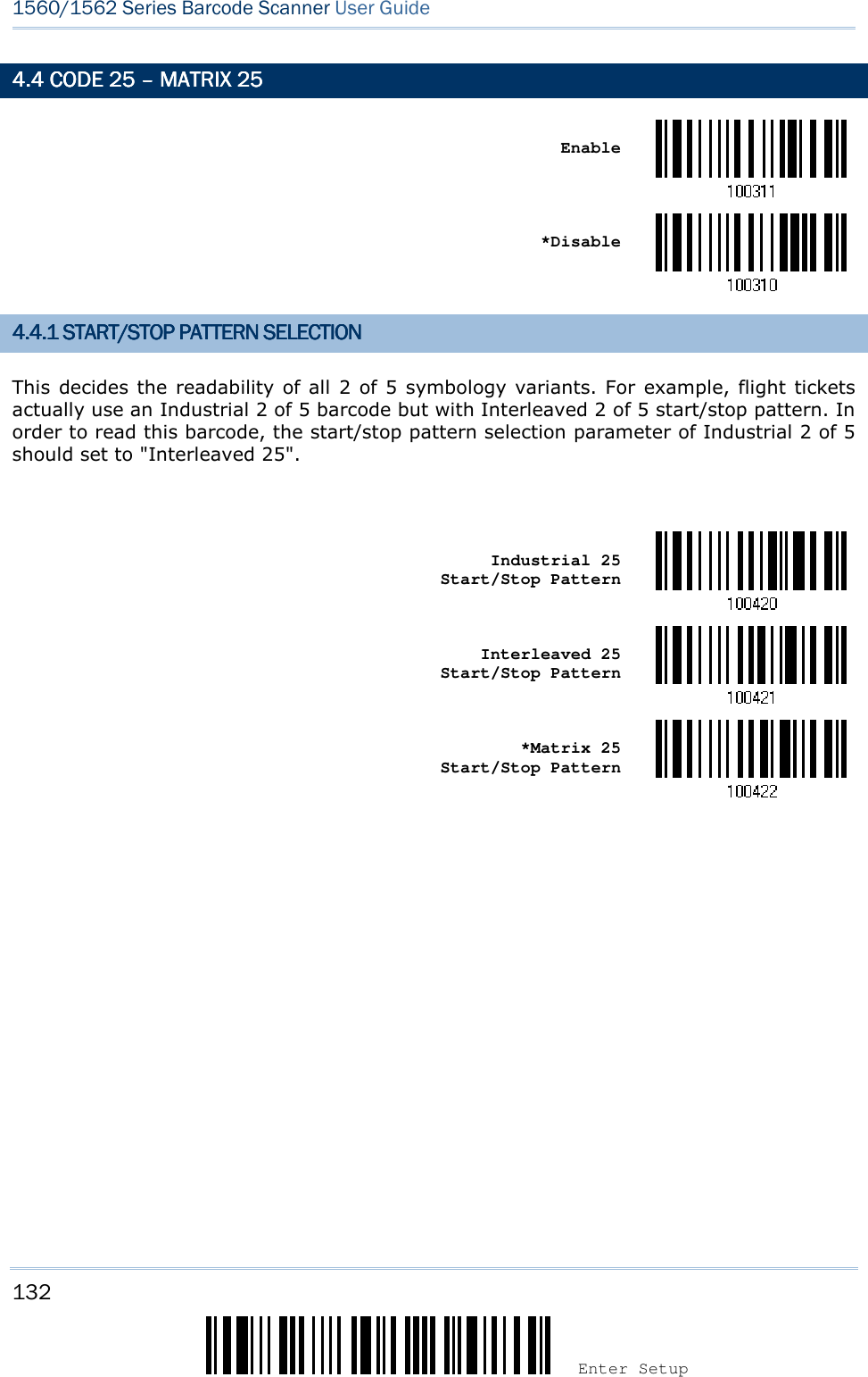
![129 Update Chapter 4 ! ! ! ! [[[[] ] ] ] Heading 1 Heading 1 Heading 1 Heading 1 4444.3 CODE 25 .3 CODE 25 .3 CODE 25 .3 CODE 25 –––– INTERLEAVED 25INTERLEAVED 25INTERLEAVED 25INTERLEAVED 25 *Enable Disable 4.3.1 START/STOP PAT4.3.1 START/STOP PAT4.3.1 START/STOP PAT4.3.1 START/STOP PATTERN SELECTIONTERN SELECTIONTERN SELECTIONTERN SELECTION This decides the readability of all 2 of 5 symbology variants. For example, flight tickets actually use an Industrial 2 of 5 barcode but with Interleaved 2 of 5 start/stop pattern. In order to read this barcode, the start/stop pattern selection parameter of Industrial 2 of 5 should set to "Interleaved 25". Industrial 25 Start/Stop Pattern *Interleaved 25 Start/Stop Pattern Matrix 25 Start/Stop Pattern](https://usermanual.wiki/CipherLab/3656CRADLE/User-Guide-3879656-Page-147.png)
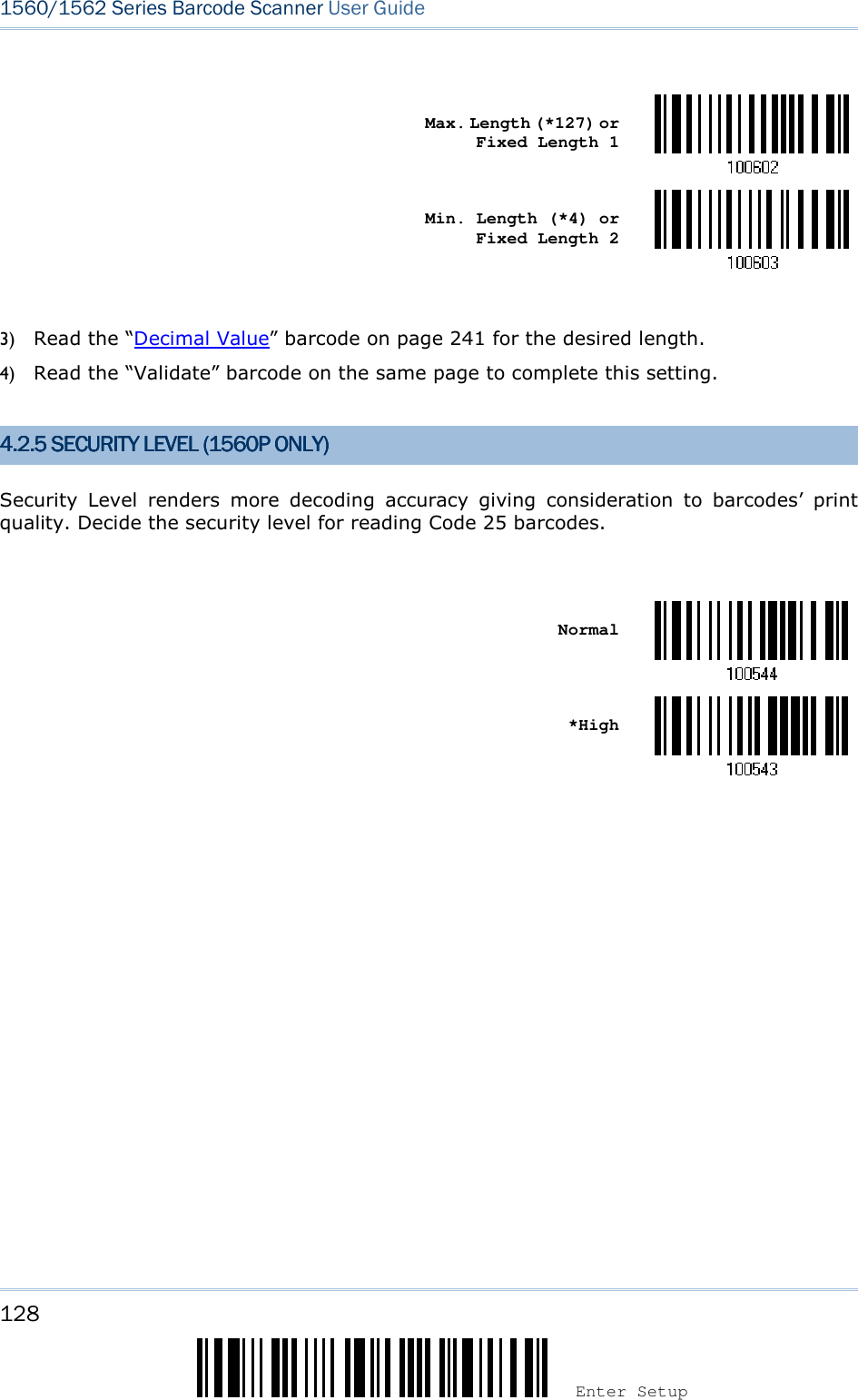
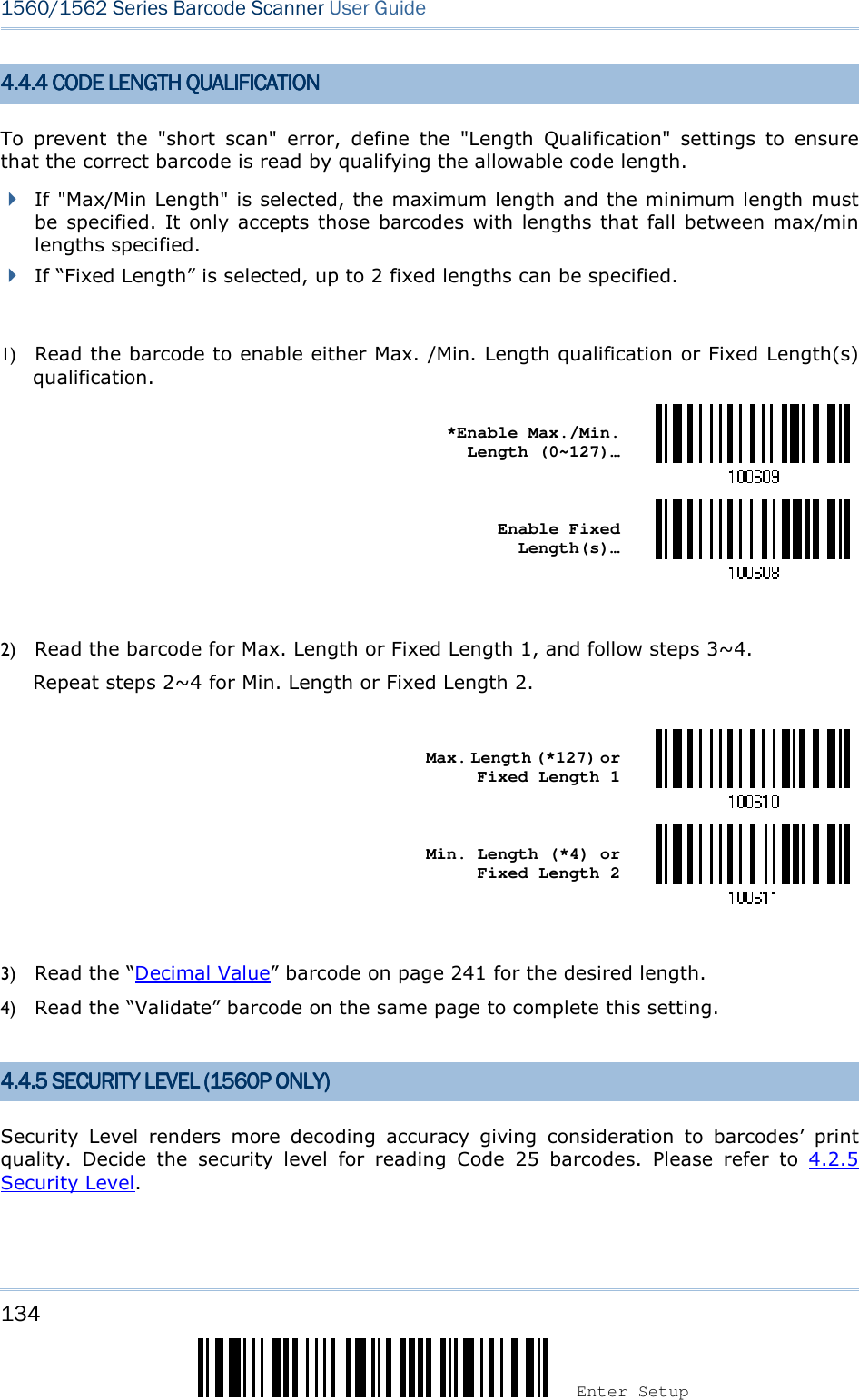
![131 Update Chapter 4 ! ! ! ! [[[[] ] ] ] Heading 1 Heading 1 Heading 1 Heading 1 4.3.4 CODE LENGTH QU4.3.4 CODE LENGTH QU4.3.4 CODE LENGTH QU4.3.4 CODE LENGTH QUALIFICATIONALIFICATIONALIFICATIONALIFICATION To prevent the "short scan" error, define the "Length Qualification" settings to ensure that the correct barcode is read by qualifying the allowable code length. If "Max/Min Length" is selected, the maximum length and the minimum length must be specified. It only accepts those barcodes with lengths that fall between max/min lengths specified. If “Fixed Length” is selected, up to 2 fixed lengths can be specified. 1) Read the barcode to enable either Max. /Min. Length qualification or Fixed Length(s) qualification. *Enable Max./Min. Length (0~127)… Enable Fixed Length(s)… 2) Read the barcode for Max. Length or Fixed Length 1, and follow steps 3~4. Repeat steps 2~4 for Min. Length or Fixed Length 2. Max. Length (*126) or Fixed Length 1 Min. Length (*4) or Fixed Length 2 3) Read the “Decimal Value” barcode on page 241 for the desired length. 4) Read the “Validate” barcode on the same page to complete this setting. 4.3.5 SESURITY LEVEL4.3.5 SESURITY LEVEL4.3.5 SESURITY LEVEL4.3.5 SESURITY LEVEL (1560P ONLY)(1560P ONLY)(1560P ONLY)(1560P ONLY) Security Level renders more decoding accuracy giving consideration to barcodes’ print quality. Decide the security level for reading Code 25 barcodes. Please refer to 4.2.5 Security Level.](https://usermanual.wiki/CipherLab/3656CRADLE/User-Guide-3879656-Page-149.png)
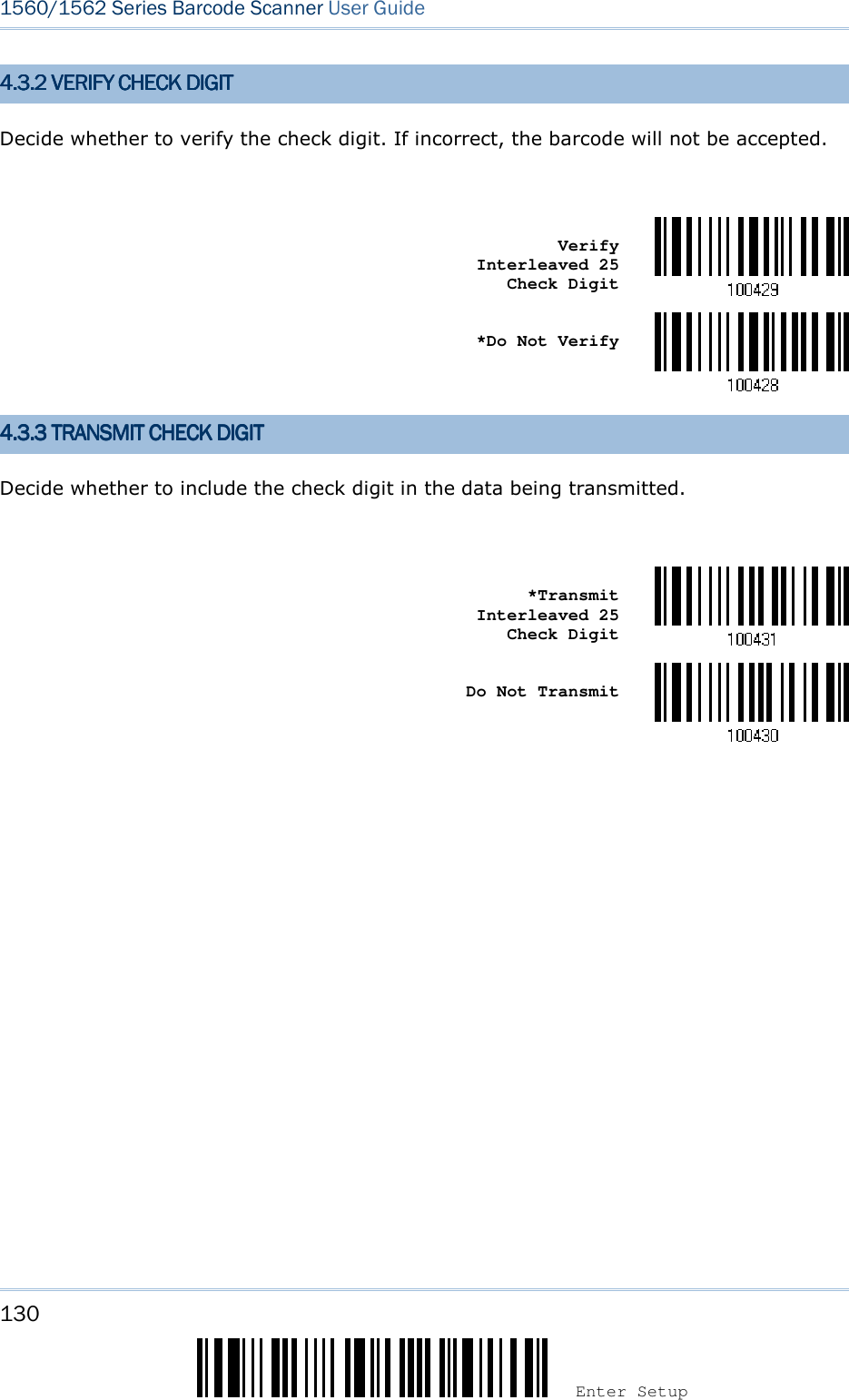
![133 Update Chapter 4 ! ! ! ! [[[[] ] ] ] Heading 1 Heading 1 Heading 1 Heading 1 4.4.2 4.4.2 4.4.2 4.4.2 VERIFY CHECK DIGITVERIFY CHECK DIGITVERIFY CHECK DIGITVERIFY CHECK DIGIT Decide whether to verify the check digit. If incorrect, the barcode will not be accepted. Verify Matrix 25 Check Digit *Do Not Verify 4.4.3 4.4.3 4.4.3 4.4.3 TRANSMIT CHECK DIGITTRANSMIT CHECK DIGITTRANSMIT CHECK DIGITTRANSMIT CHECK DIGIT Decide whether to include the check digit in the data being transmitted. *Transmit Matrix 25 Check Digit Do Not Transmit](https://usermanual.wiki/CipherLab/3656CRADLE/User-Guide-3879656-Page-151.png)
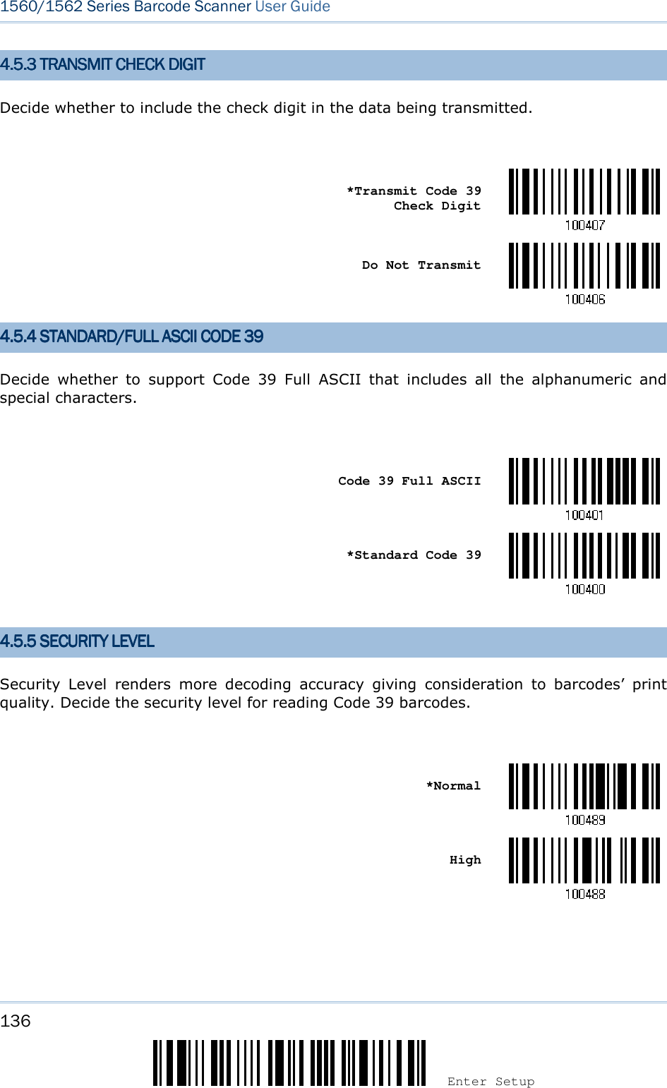
![135 Update Chapter 4 ! ! ! ! [[[[] ] ] ] Heading 1 Heading 1 Heading 1 Heading 1 4.4.4.4.5555 CODE 39CODE 39CODE 39CODE 39 *Enable Disable 4.5.1 START4.5.1 START4.5.1 START4.5.1 START/S/S/S/STOP TRANSMISSIONTOP TRANSMISSIONTOP TRANSMISSIONTOP TRANSMISSION Decide whether to include the start/stop characters in the data being transmitted. Transmit Code 39 Start/Stop Characters *Do Not Transmit 4.5.2 4.5.2 4.5.2 4.5.2 VERIFY CHECK DIGITVERIFY CHECK DIGITVERIFY CHECK DIGITVERIFY CHECK DIGIT Decide whether to verify check digit. If incorrect, the barcode will not be accepted. Verify Code 39 Check Digit *Do Not Verify](https://usermanual.wiki/CipherLab/3656CRADLE/User-Guide-3879656-Page-153.png)
![137 Update Chapter 4 ! ! ! ! [[[[] ] ] ] Heading 1 Heading 1 Heading 1 Heading 1 4.5.6 ASTERISK4.5.6 ASTERISK4.5.6 ASTERISK4.5.6 ASTERISKS S S S (*) (*) (*) (*) AS DATA CHARACTERSAS DATA CHARACTERSAS DATA CHARACTERSAS DATA CHARACTERS Decide whether to take asterisk (*) as part of the data. Enable *Disable 4.6 TRIOPTIC CODE 394.6 TRIOPTIC CODE 394.6 TRIOPTIC CODE 394.6 TRIOPTIC CODE 39 Enable *Disable 4.4.4.4.7777 CODE 93CODE 93CODE 93CODE 93 *Enable Disable 4.4.4.4.8888 CODE 128CODE 128CODE 128CODE 128 *Enable Disable](https://usermanual.wiki/CipherLab/3656CRADLE/User-Guide-3879656-Page-155.png)
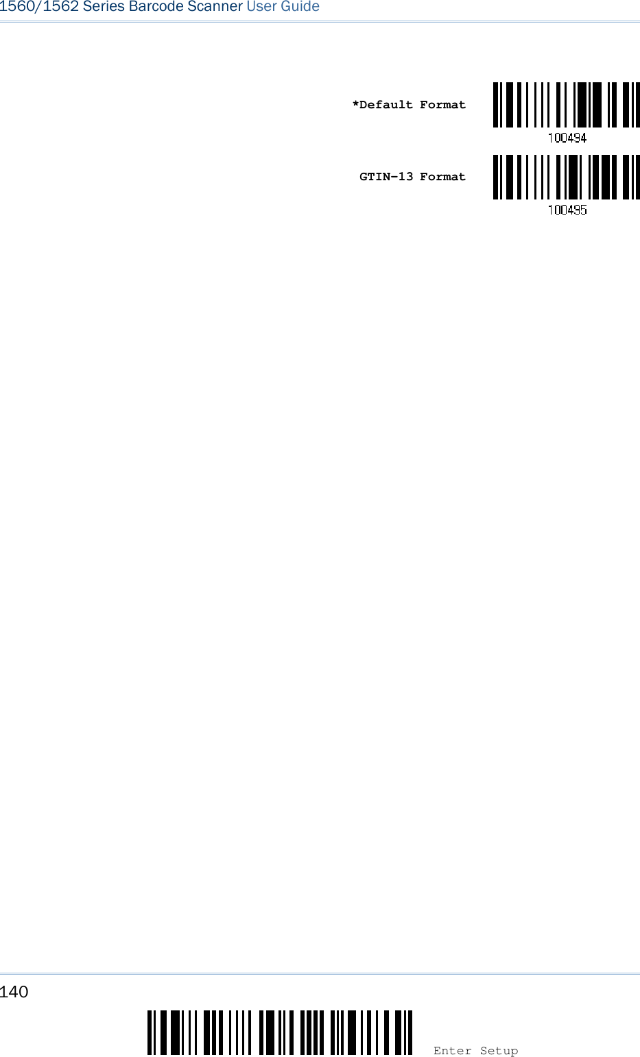
![139 Update Chapter 4 ! ! ! ! [[[[] ] ] ] Heading 1 Heading 1 Heading 1 Heading 1 4.4.4.4.9999.1.1.1.1 CONVERT TO EANCONVERT TO EANCONVERT TO EANCONVERT TO EAN----13131313 Decide whether to expand the read EAN-8 barcode, as well as its addons, into EAN-13. After conversion, the data follows EAN-13 format and is affected by EAN-13 programming selections (e.g. Check Digit). Convert EAN-8 to EAN-13 *Do Not Convert 4.4.4.4.9999....2 2 2 2 TRANSMIT CHECK DIGITTRANSMIT CHECK DIGITTRANSMIT CHECK DIGITTRANSMIT CHECK DIGIT Decide whether to include the check digit in the data being transmitted. *Transmit EAN-8 Check Digit Do Not Transmit 4.4.4.4.9999.3 CONVERSION FO.3 CONVERSION FO.3 CONVERSION FO.3 CONVERSION FORMATRMATRMATRMAT When converting EAN-8 to EAN-13, you can scan the barcode below to decide conversion in default or GTIN-13 format.](https://usermanual.wiki/CipherLab/3656CRADLE/User-Guide-3879656-Page-157.png)
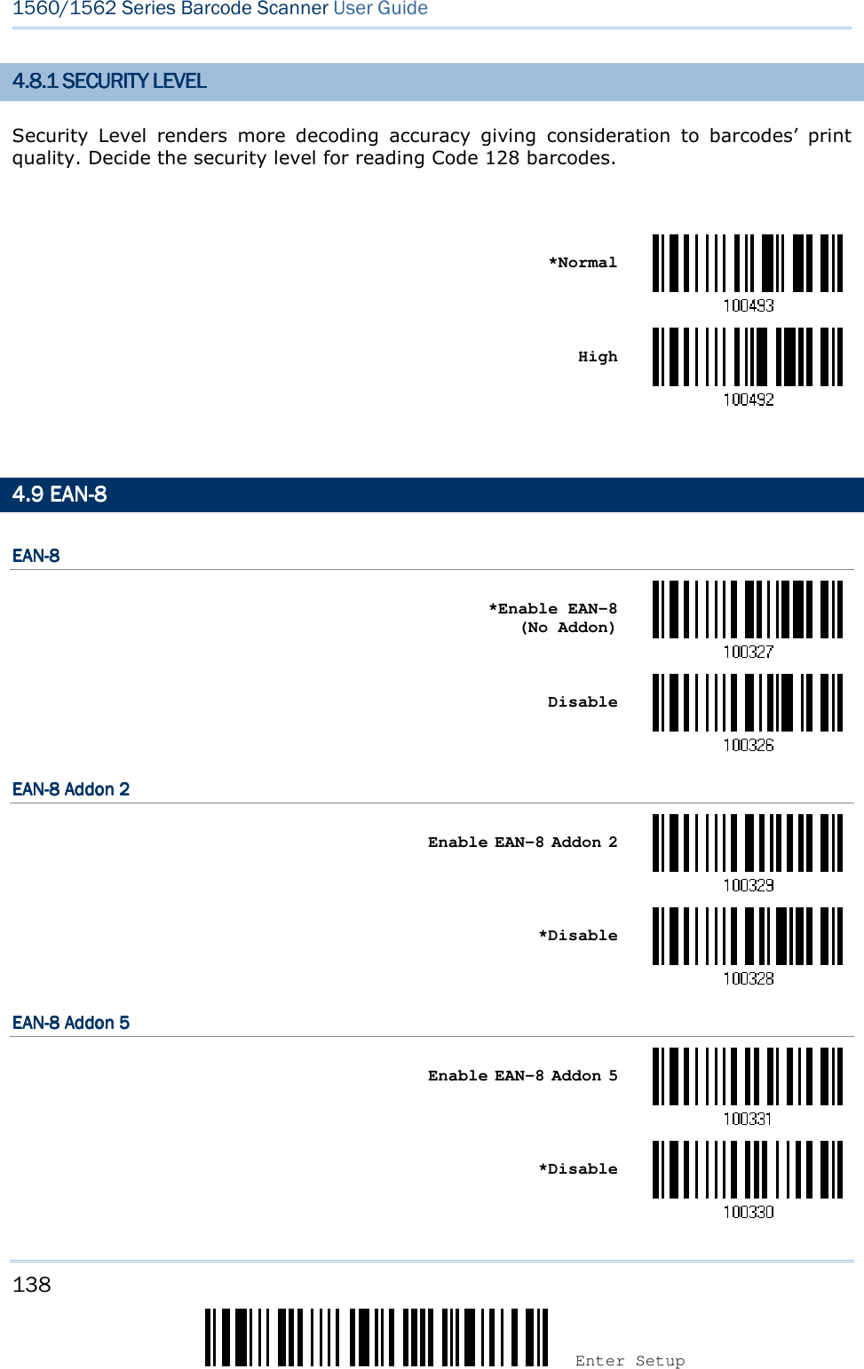
![141 Update Chapter 4 ! ! ! ! [[[[] ] ] ] Heading 1 Heading 1 Heading 1 Heading 1 4.4.4.4.10101010 EANEANEANEAN----13131313 EANEANEANEAN----13131313 *Enable EAN-13 (No Addon) Disable EANEANEANEAN----13 Addon 213 Addon 213 Addon 213 Addon 2 Enable EAN-13 Addon 2 *Disable EANEANEANEAN----13 Addon 513 Addon 513 Addon 513 Addon 5 Enable EAN-13 Addon 5 *Disable](https://usermanual.wiki/CipherLab/3656CRADLE/User-Guide-3879656-Page-159.png)
![143 Update Chapter 4 ! ! ! ! [[[[] ] ] ] Heading 1 Heading 1 Heading 1 Heading 1 4.104.104.104.10....4444 SSSSECURITY LEVELECURITY LEVELECURITY LEVELECURITY LEVEL Security Level renders more decoding accuracy giving consideration to barcodes’ print quality. Decide the security level for reading EAN-13 barcodes. *Normal High](https://usermanual.wiki/CipherLab/3656CRADLE/User-Guide-3879656-Page-161.png)
![144 Enter Setup 1560/1562 Series Barcode Scanner User Guide 4.4.4.4.11111111 GS1GS1GS1GS1----128 (128 (128 (128 (EANEANEANEAN----128128128128)))) *Enable Disable Note: When this setting is disabled, GS1-128 barcodes used to be taken as Code 128. However, starting from firmware version 1.01, GS1-128 barcodes can be decoded only when this setting is enabled. 4.4.4.4.11111111.1 CODE ID TRANSMISS.1 CODE ID TRANSMISS.1 CODE ID TRANSMISS.1 CODE ID TRANSMISSIONIONIONION Decide whether to include the Code ID ("]C1") in the data being transmitted. Transmit Code ID *Do Not Transmit 4.4.4.4.11111111.2 FIELD SEPARATOR (.2 FIELD SEPARATOR (.2 FIELD SEPARATOR (.2 FIELD SEPARATOR (GS CHARACTER)GS CHARACTER)GS CHARACTER)GS CHARACTER) Decide whether to apply a field separator (to convert the FNC1 control character to human readable character). Enable Field Separator… 1) Read the barcode above to enable field separator. 2) Read the “Hexadecimal Value” barcode on page 242 for the desired character string. 3) Read the “Validate” barcode to complete this setting. Note: GS1-128 barcodes start with the FNC1 control character to distinguish themselves from other uses of Code 128. FNC1 is also used to separate data fields in the GS1-128 barcodes.](https://usermanual.wiki/CipherLab/3656CRADLE/User-Guide-3879656-Page-162.png)
![145 Update Chapter 4 ! ! ! ! [[[[] ] ] ] HeaHeaHeaHeading 1 ding 1 ding 1 ding 1 4.14.14.14.11111.3.3.3.3 GS1 FORMATTINGGS1 FORMATTINGGS1 FORMATTINGGS1 FORMATTING Decide whether to enable GS1 formatting for GS1-128. Enable *Disable 4.14.14.14.11111.4 APPLICATION ID.4 APPLICATION ID.4 APPLICATION ID.4 APPLICATION ID MARKMARKMARKMARK Decide whether to add an application ID mark (1 character) to the left (AIMark1) or right (AIMark2) of an application ID (AI) for the purpose of labeling it when formatting the GS1 data. AIMark1 AIMark2 1) Read the barcode above to add a mark to the left (AIMark1)/right (AIMark2) of an application ID. 2) Read the “Hexadecimal Value” barcode on page 242 for the desired character string. Read ‘00’ if you want to remove the AI mark. 3) Read the “Validate” barcode to complete this setting.](https://usermanual.wiki/CipherLab/3656CRADLE/User-Guide-3879656-Page-163.png)
![147 Update Chapter 4 ! ! ! ! [[[[] ] ] ] Heading 1 Heading 1 Heading 1 Heading 1 4.4.4.4.11113333 MSIMSIMSIMSI Enable *Disable 4.4.4.4.11113333.1 .1 .1 .1 VERIFY CHECK DIGITVERIFY CHECK DIGITVERIFY CHECK DIGITVERIFY CHECK DIGIT Select one of the three calculations to verify check digit when decoding barcodes. If incorrect, the barcode will not be accepted. *Single Modulo 10 Double Modulo 10 Modulo 10 & 11 4.14.14.14.13333....2 2 2 2 TRANSMIT CHECK DIGITTRANSMIT CHECK DIGITTRANSMIT CHECK DIGITTRANSMIT CHECK DIGIT Decide whether to include the check digit in the data being transmitted. *Last Digit Not Transmitted Both Digits Transmitted Both Digits Not Transmitted](https://usermanual.wiki/CipherLab/3656CRADLE/User-Guide-3879656-Page-165.png)
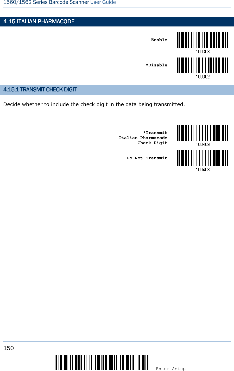
![149 Update Chapter 4 ! ! ! ! [[[[] ] ] ] Heading 1 Heading 1 Heading 1 Heading 1 4.14.14.14.14444 FRENCH FRENCH FRENCH FRENCH PHARMACODEPHARMACODEPHARMACODEPHARMACODE Enable *Disable 4.14.14.14.14444.1.1.1.1 TRANSMIT CHECK DIGITTRANSMIT CHECK DIGITTRANSMIT CHECK DIGITTRANSMIT CHECK DIGIT Decide whether to include the check digit in the data being transmitted. *Transmit French Pharmacode Check Digit Do Not Transmit](https://usermanual.wiki/CipherLab/3656CRADLE/User-Guide-3879656-Page-167.png)
![151 Update Chapter 4 ! ! ! ! [[[[]]]] Heading 1 Heading 1 Heading 1 Heading 1 4.14.14.14.16666 PLESSEYPLESSEYPLESSEYPLESSEY Enable *Disable 4.14.14.14.16666.1 CONVERT TO UK PLE.1 CONVERT TO UK PLE.1 CONVERT TO UK PLE.1 CONVERT TO UK PLESSEYSSEYSSEYSSEY Decide whether to change each occurrence of the character 'A' to character 'X' in the decoded data. Convert to UK Plessey *Do Not Convert 4.14.14.14.16666.2 .2 .2 .2 TRANSMIT CHECK DIGITTRANSMIT CHECK DIGITTRANSMIT CHECK DIGITTRANSMIT CHECK DIGIT Decide whether to include the two check digits in the data being transmitted. *Transmit Plessey Check Digits Do Not Transmit](https://usermanual.wiki/CipherLab/3656CRADLE/User-Guide-3879656-Page-169.png)
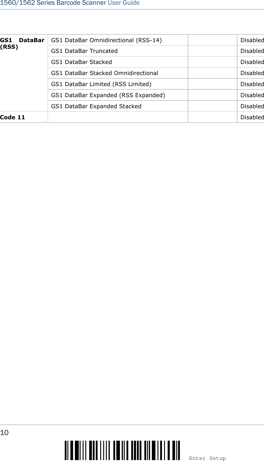
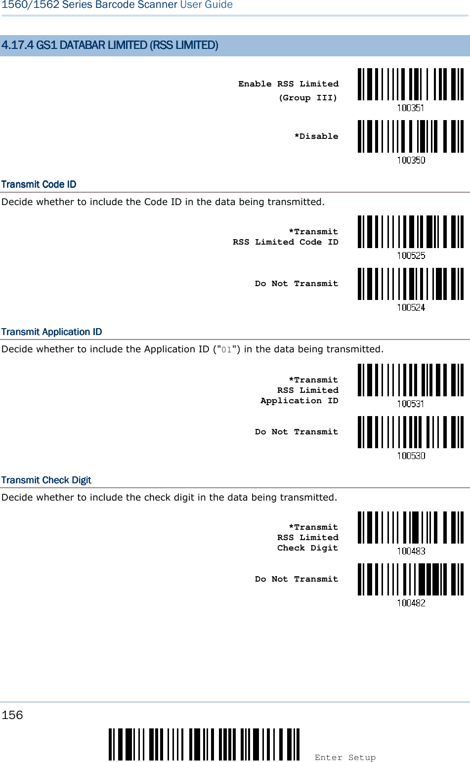
![152 Enter Setup 1560/1562 Series Barcode Scanner User Guide 4.14.14.14.17777 GS1 DAGS1 DAGS1 DAGS1 DATATATATABBBBAR (AR (AR (AR (RSS FAMILYRSS FAMILYRSS FAMILYRSS FAMILY)))) It is categorized into three groups: Group I Group I Group I Group I ———— GS1 DataBar Omnidirectional (RSSGS1 DataBar Omnidirectional (RSSGS1 DataBar Omnidirectional (RSSGS1 DataBar Omnidirectional (RSS----14)14)14)14) This group consists of the following: GS1 DataBar Omnidirectional GS1 DataBar Truncated GS1 DataBar Stacked GS1 DataBar Stacked Omnidirectional GrouGrouGrouGroup IIp IIp IIp II ———— GS1 DataBar Expanded (RSS Expanded)GS1 DataBar Expanded (RSS Expanded)GS1 DataBar Expanded (RSS Expanded)GS1 DataBar Expanded (RSS Expanded) This group consists of the following: GS1 DataBar Expanded GS1 DataBar Expanded Stacked Group III Group III Group III Group III ———— GS1 DataBar Limited (RSS Limited)GS1 DataBar Limited (RSS Limited)GS1 DataBar Limited (RSS Limited)GS1 DataBar Limited (RSS Limited) This group consists of the following: GS1 DataBar Limited 4.14.14.14.17777.1 CODE I.1 CODE I.1 CODE I.1 CODE ID SELECTIOND SELECTIOND SELECTIOND SELECTION Select a desired Code ID to use: “]e0“ (GS1 DataBar Code ID) “]C1” (GS1-128 Code ID) Use “]C1” *Use “]e0”](https://usermanual.wiki/CipherLab/3656CRADLE/User-Guide-3879656-Page-170.png)
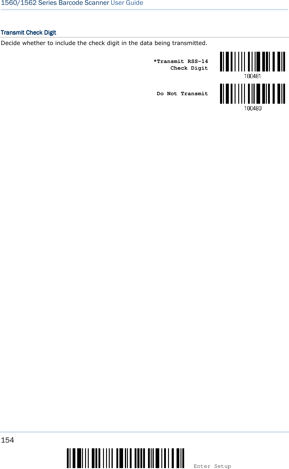
![153 Update Chapter 4 ! ! ! ! [[[[] ] ] ] Heading 1 Heading 1 Heading 1 Heading 1 4.14.14.14.17777.2 .2 .2 .2 GS1 DATAGS1 DATAGS1 DATAGS1 DATABBBBAR OMNIDIRECTIONAL (AR OMNIDIRECTIONAL (AR OMNIDIRECTIONAL (AR OMNIDIRECTIONAL (RSSRSSRSSRSS----14)14)14)14) Enable RSS-14 & RSS Expanded (Groups I, II) *Disable The settings below apply to Group I symbologies only: GS1 DataBar Omnidirectional GS1 DataBar Truncated GS1 DataBar Stacked GS1 DataBar Stacked Omnidirectional Transmit Code IDTransmit Code IDTransmit Code IDTransmit Code ID Decide whether to include the Code ID in the data being transmitted. *Transmit RSS-14 Code ID Do Not Transmit Transmit Application IDTransmit Application IDTransmit Application IDTransmit Application ID Decide whether to include the Application ID ("01") in the data being transmitted. *Transmit RSS-14 Application ID Do Not Transmit](https://usermanual.wiki/CipherLab/3656CRADLE/User-Guide-3879656-Page-171.png)
![155 Update Chapter 4 ! ! ! ! [[[[] ] ] ] Heading 1 Heading 1 Heading 1 Heading 1 4.14.14.14.17777.3 .3 .3 .3 GS1 DATAGS1 DATAGS1 DATAGS1 DATABBBBAR EXPANDED (AR EXPANDED (AR EXPANDED (AR EXPANDED (RSS EXPANDEDRSS EXPANDEDRSS EXPANDEDRSS EXPANDED)))) Enable RSS-14 & RSS Expanded (Groups I, II) *Disable The settings below apply to Group II symbologies only: GS1 DataBar Expanded GS1 DataBar Expanded Stacked Transmit Code IDTransmit Code IDTransmit Code IDTransmit Code ID Decide whether to include the Code ID in the data being transmitted. *Transmit RSS Expanded Code ID Do Not Transmit](https://usermanual.wiki/CipherLab/3656CRADLE/User-Guide-3879656-Page-173.png)
![157 Update Chapter 4 ! ! ! ! [[[[] ] ] ] Heading 1 Heading 1 Heading 1 Heading 1 4.14.14.14.17777.5 FIELD SEPARATOR.5 FIELD SEPARATOR.5 FIELD SEPARATOR.5 FIELD SEPARATOR (GS CHARACTER)(GS CHARACTER)(GS CHARACTER)(GS CHARACTER) Decide whether to apply a field separator (to convert the GS control character to human readable character). Enable Field Separator… 1) Read the barcode above to enable field separator. 2) Read the “Hexadecimal Value” barcode on page 242 for the desired character string. 3) Read the “Validate” barcode to complete this setting. 4.14.14.14.17.7.7.7.6 GS1 FORMATTING6 GS1 FORMATTING6 GS1 FORMATTING6 GS1 FORMATTING Decide whether to enable GS1 formatting for GS1 DataBar (RSS family). Enable *Disable 4.14.14.14.17777.7 APPLICATION ID .7 APPLICATION ID .7 APPLICATION ID .7 APPLICATION ID MMMMARKARKARKARK Decide whether to add an application ID mark (1 character) to the left (AIMark1) or right (AIMark2) of an application ID (AI) for the purpose of labeling it when formatting the GS1 data. AIMark1 AIMark2 1) Read the barcode above to add a mark to the left (AIMark1)/right (AIMark2) of an application ID. 2) Read the “Hexadecimal Value” barcode on page 242 for the desired character string. Read '00' if you want to remove the AI mark. 3) Read the “Validate” barcode to complete this setting.](https://usermanual.wiki/CipherLab/3656CRADLE/User-Guide-3879656-Page-175.png)
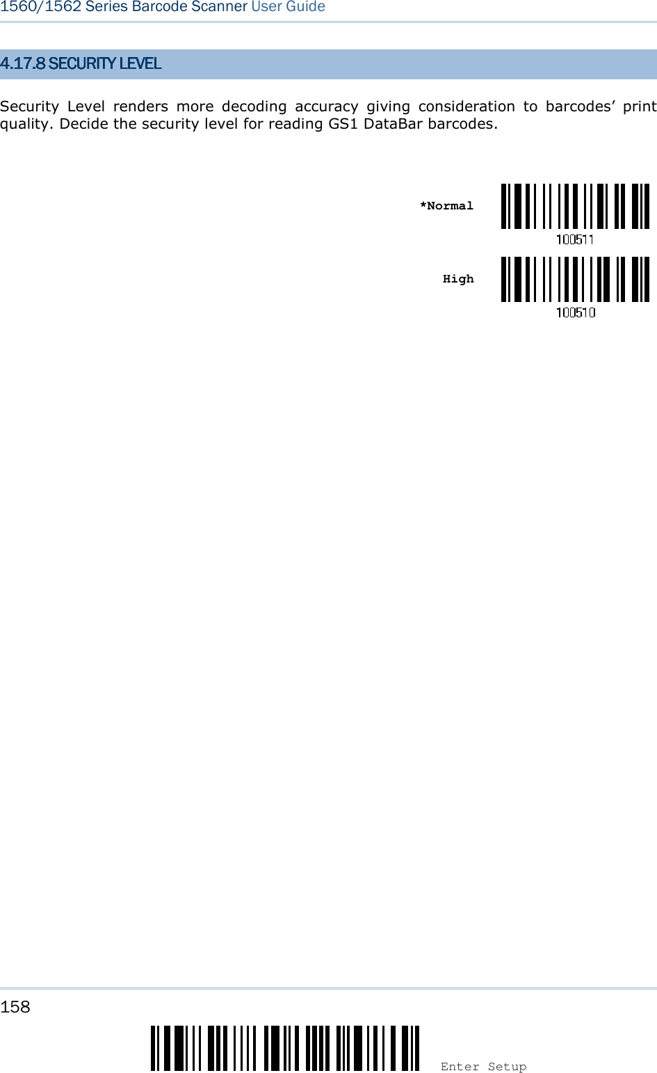
![159 Update Chapter 4 ! ! ! ! [[[[] ] ] ] Heading 1 Heading 1 Heading 1 Heading 1 4.14.14.14.18888 TELEPENTELEPENTELEPENTELEPEN Enable Telepen *Disable 4.14.14.14.18888.1 TELEPEN OUTPUT .1 TELEPEN OUTPUT .1 TELEPEN OUTPUT .1 TELEPEN OUTPUT –––– FULL ASCII/NUFULL ASCII/NUFULL ASCII/NUFULL ASCII/NUMERICMERICMERICMERIC Decide whether to support Telepen in full ASCII code. By default, it supports ASCII mode. AIM Telepen (Full ASCII) includes all the alphanumeric and special characters. Original Telepen (Numeric) *AIM Telepen](https://usermanual.wiki/CipherLab/3656CRADLE/User-Guide-3879656-Page-177.png)
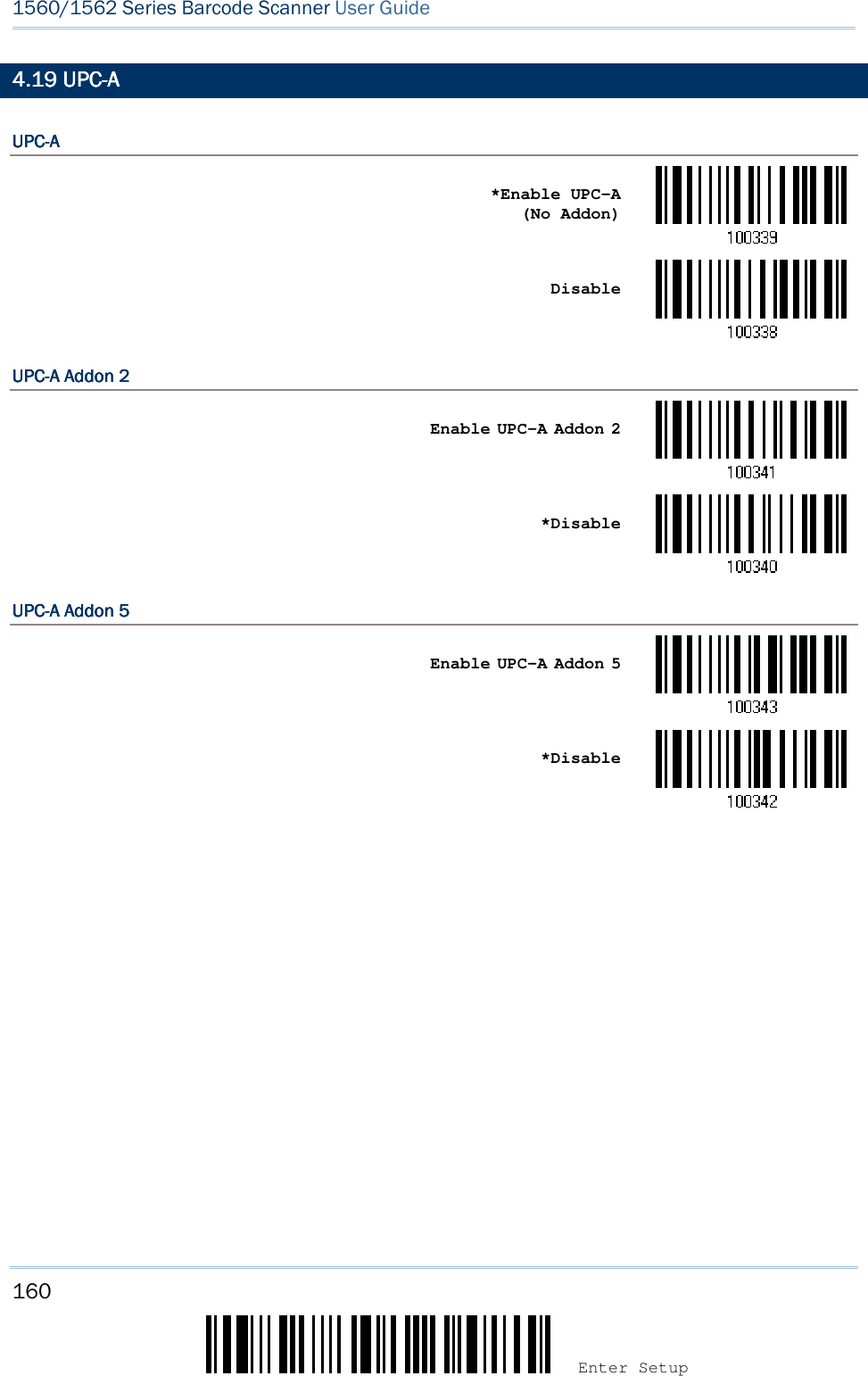
![161 Update Chapter 4 ! ! ! ! [[[[] ] ] ] Heading 1 Heading 1 Heading 1 Heading 1 4.14.14.14.19999.1 CONVERT TO EAN.1 CONVERT TO EAN.1 CONVERT TO EAN.1 CONVERT TO EAN----13131313 Decide whether to expand the read UPC-A barcode, as well as its addons, into EAN-13. After conversion, the data follows EAN-13 format and is affected by EAN-13 programming selections (e.g. Check Digit). Convert UPC-A to EAN-13 *Do Not Convert 4.14.14.14.19999.2 SYSTEM NUMBER TRA.2 SYSTEM NUMBER TRA.2 SYSTEM NUMBER TRA.2 SYSTEM NUMBER TRANSMISSIONNSMISSIONNSMISSIONNSMISSION Decide whether to include the system number in the data being transmitted. *Transmit UPC-A System Number Do Not Transmit 4.14.14.14.19999.3 .3 .3 .3 TRANSMIT CHECK DIGITTRANSMIT CHECK DIGITTRANSMIT CHECK DIGITTRANSMIT CHECK DIGIT Decide whether to include the check digit in the data being transmitted. *Transmit UPC-A Check Digit Do Not Transmit](https://usermanual.wiki/CipherLab/3656CRADLE/User-Guide-3879656-Page-179.png)
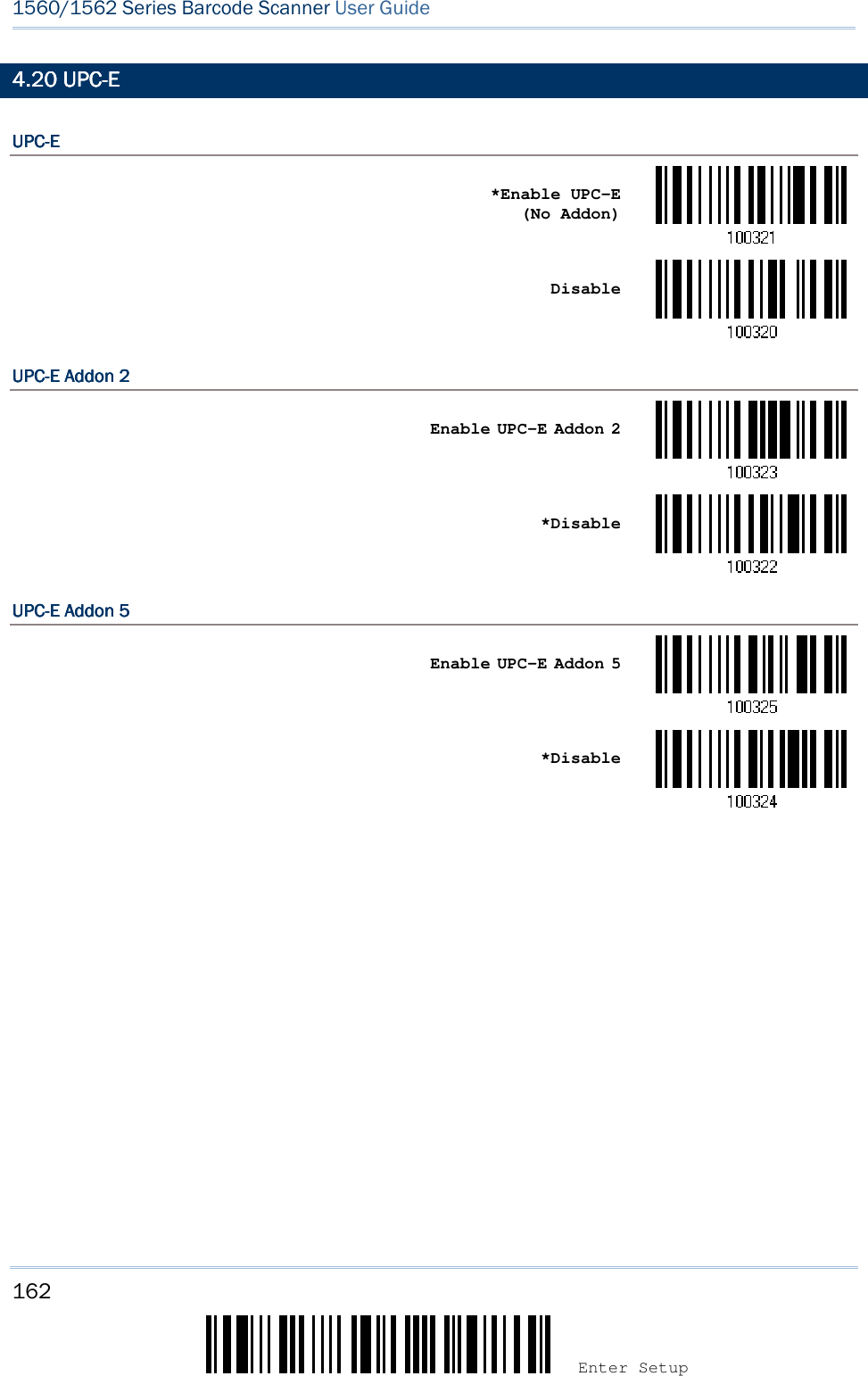
![163 Update Chapter 4 ! ! ! ! [[[[] ] ] ] Heading 1 Heading 1 Heading 1 Heading 1 4.4.4.4.20202020.1 SYSTEM NUMBER SEL.1 SYSTEM NUMBER SEL.1 SYSTEM NUMBER SEL.1 SYSTEM NUMBER SELECTIONECTIONECTIONECTION Decide whether to decode the ordinary UPC-E barcodes only or both UPC-E0 and UPC-E1 barcodes. System number 0 enabled for decoding UPC-E0 barcodes. System number 1 enabled for decoding UPC-E1 barcodes. System Number 0 & 1 *System Number 0 Only Warning: Because of the way system number 1 is encoded, if both system numbers are enabled, the user might suffer from short scanning UPC-A or EAN-13 barcodes into UPC-E1 barcodes. 4.4.4.4.20202020.2 CONVERT TO UPC.2 CONVERT TO UPC.2 CONVERT TO UPC.2 CONVERT TO UPC----AAAA Decide whether to expand the read UPC-E barcode, as well as its addons, into UPC-A. After conversion, the data follows UPC-A format and is affected by UPC-A programming selections (e.g. System Number, Check Digit). Convert UPC-E to UPC-A *Do Not Convert](https://usermanual.wiki/CipherLab/3656CRADLE/User-Guide-3879656-Page-181.png)
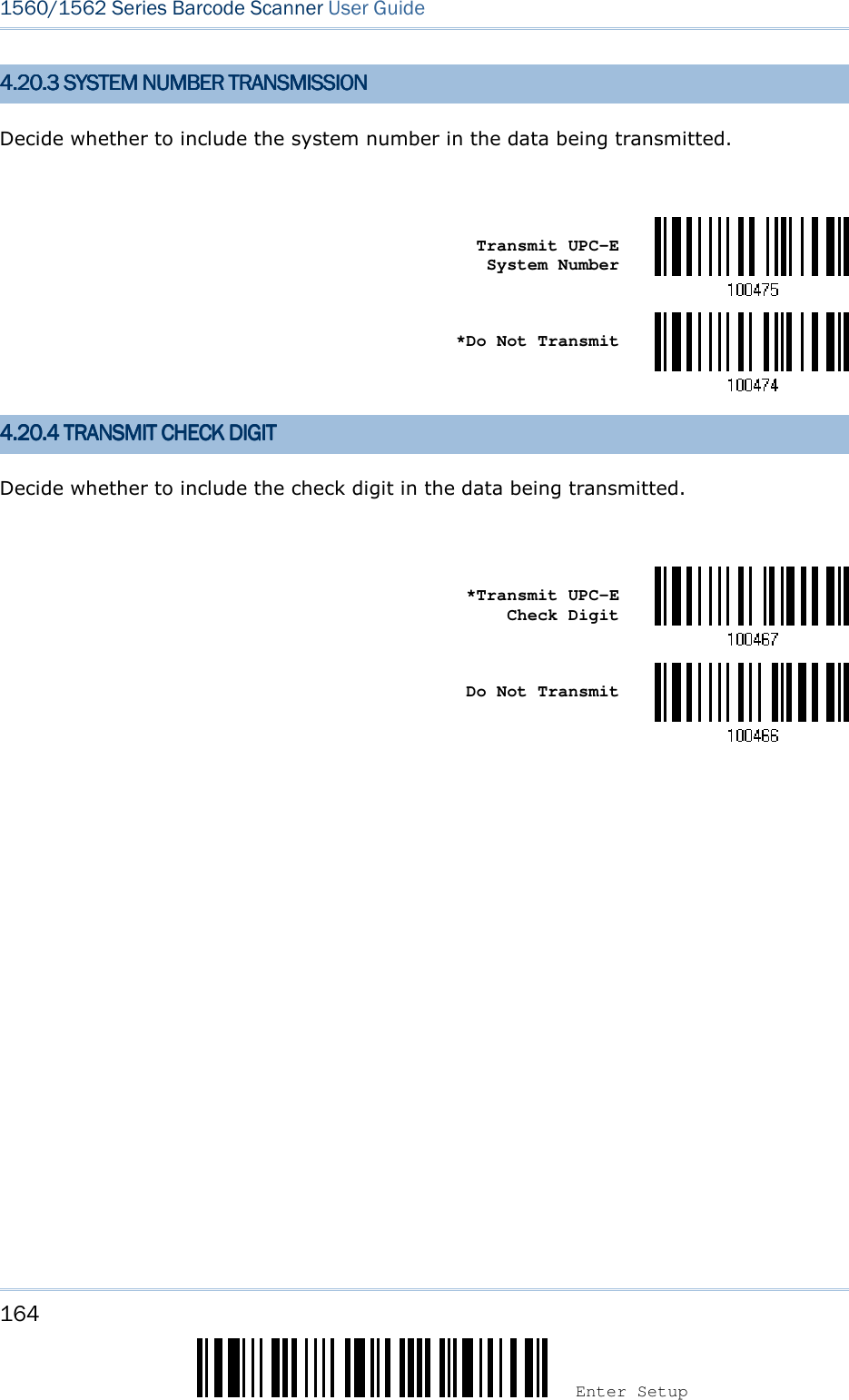
![165 Update Chapter 4 ! ! ! ! [[[[] ] ] ] Heading 1 Heading 1 Heading 1 Heading 1 4.214.214.214.21 CODE 11CODE 11CODE 11CODE 11 Enable *Disable 4.214.214.214.21.1 .1 .1 .1 VERIFVERIFVERIFVERIFY CHECK DIGITY CHECK DIGITY CHECK DIGITY CHECK DIGIT Select one of the verification when decoding barcodes. If incorrect, the barcode will not be accepted. None Double Single *Auto](https://usermanual.wiki/CipherLab/3656CRADLE/User-Guide-3879656-Page-183.png)
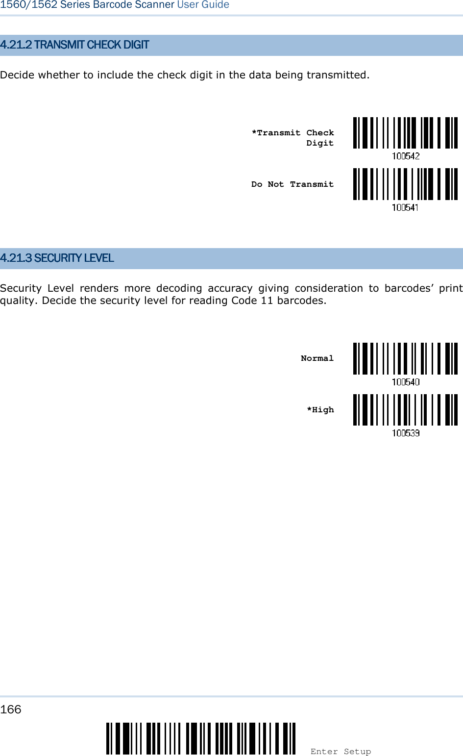
![167 Update You may configure in which format the collected data will be output to the host computer. Barcode read by the scanner will be processed in the following sequence – 1) Perform character substitution on the data scanned. 2) Add Code ID and Length Code to the front of the data:[Code ID][Length Code][Data] 3) Process the whole data in step 2 with user formats. Data is now divided into fields by user specified rules. Refer to Chapter 6 Applying Formats for Data Editing. 4) Add Prefix Code and Suffix Code before transmission:[Prefix Code][Processed Data][Suffix Code] IN THIS CHAPTERIN THIS CHAPTERIN THIS CHAPTERIN THIS CHAPTER 5.1 Letter Case .............................................................. 167 5.2 Character Substitution ............................................... 168 5.3 Prefix/Suffix Code ..................................................... 176 5.4 Code ID ................................................................... 177 5.5 Length Code ............................................................. 182 5.6 Multi-Barcode Editor .................................................. 186 5.7 Removal of Special Character ..................................... 190 5.1 LETTER CASE5.1 LETTER CASE5.1 LETTER CASE5.1 LETTER CASE By default, the alphabets transmission is case-sensitive, meaning that the alphabets will be transmitted according to their original case. Ignoring the original letter case, select [Upper Case] to output data in upper case only; otherwise, select [Lower Case] to output data in lower case only. *Normal Upper Case Lower Case Chapter Chapter Chapter Chapter 5555 DDDDEFINING OUTEFINING OUTEFINING OUTEFINING OUTPUT FORMATPUT FORMATPUT FORMATPUT FORMAT](https://usermanual.wiki/CipherLab/3656CRADLE/User-Guide-3879656-Page-185.png)
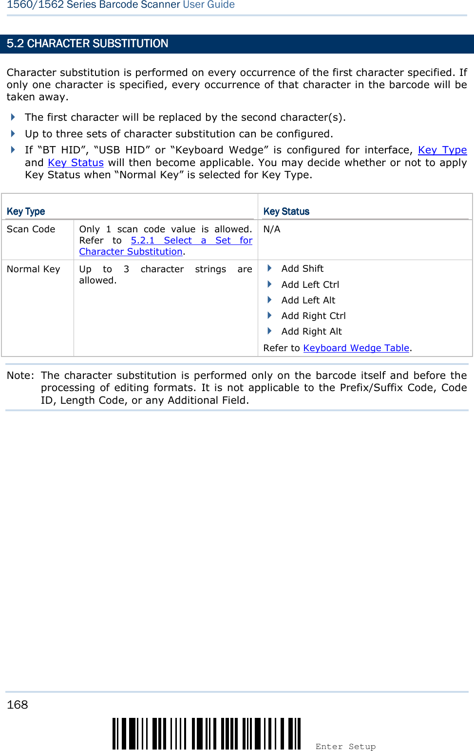
![169 Update Chapter 5 ! ! ! ! [[[[] ] ] ] Heading 1 Heading 1 Heading 1 Heading 1 5.2.1 SELECT A SET F5.2.1 SELECT A SET F5.2.1 SELECT A SET F5.2.1 SELECT A SET FOR CHARACTER SOR CHARACTER SOR CHARACTER SOR CHARACTER SUBSTITUUBSTITUUBSTITUUBSTITUTTTTIONIONIONION Configure Set 1 Configure Set 2 Configure Set 3 1) Read the barcode above to enable character substitution by set. For example, have the scanner read the “Set 1” barcode to configure the first set of character substitution. The scanner will respond with one short beep, high tone, to indicate more setup barcodes are required. 2) Read the “Hexadecimal Value” barcode on page 242 for the desired character substitution. For example, KEY TYPE = NORMALKEY TYPE = NORMALKEY TYPE = NORMALKEY TYPE = NORMAL Read “3”, “0”, “2”, and “D” to replace the character “0” with a dash “-”. Read “3”, “0”, “2”, “D”, “3”, and “0” to replace the character “0” with a dash “-0”. KEY TYPE = SCAN CODEKEY TYPE = SCAN CODEKEY TYPE = SCAN CODEKEY TYPE = SCAN CODE If you want to replace the character “0” with “a” (= “1C” on the scan code table): 1. Read “3” and “0”. 2. Read the “Scan Code” barcode. 3. Read “1” and “C”. KEY TYPE = NORMAL + KEY TYPE = NORMAL + KEY TYPE = NORMAL + KEY TYPE = NORMAL + KEY STATUS = SHIFTKEY STATUS = SHIFTKEY STATUS = SHIFTKEY STATUS = SHIFT If you want to replace the character “0” with “!” (= “Shift” + “1” on keyboard): 1. Read “3” and “0”. 2. Read the “Add Shift” barcode. 3. Read “3” and “1”. 3) Read the “Validate” barcode to complete this setting. (The defined set or sets will be applied to all symbologies by default.)](https://usermanual.wiki/CipherLab/3656CRADLE/User-Guide-3879656-Page-187.png)
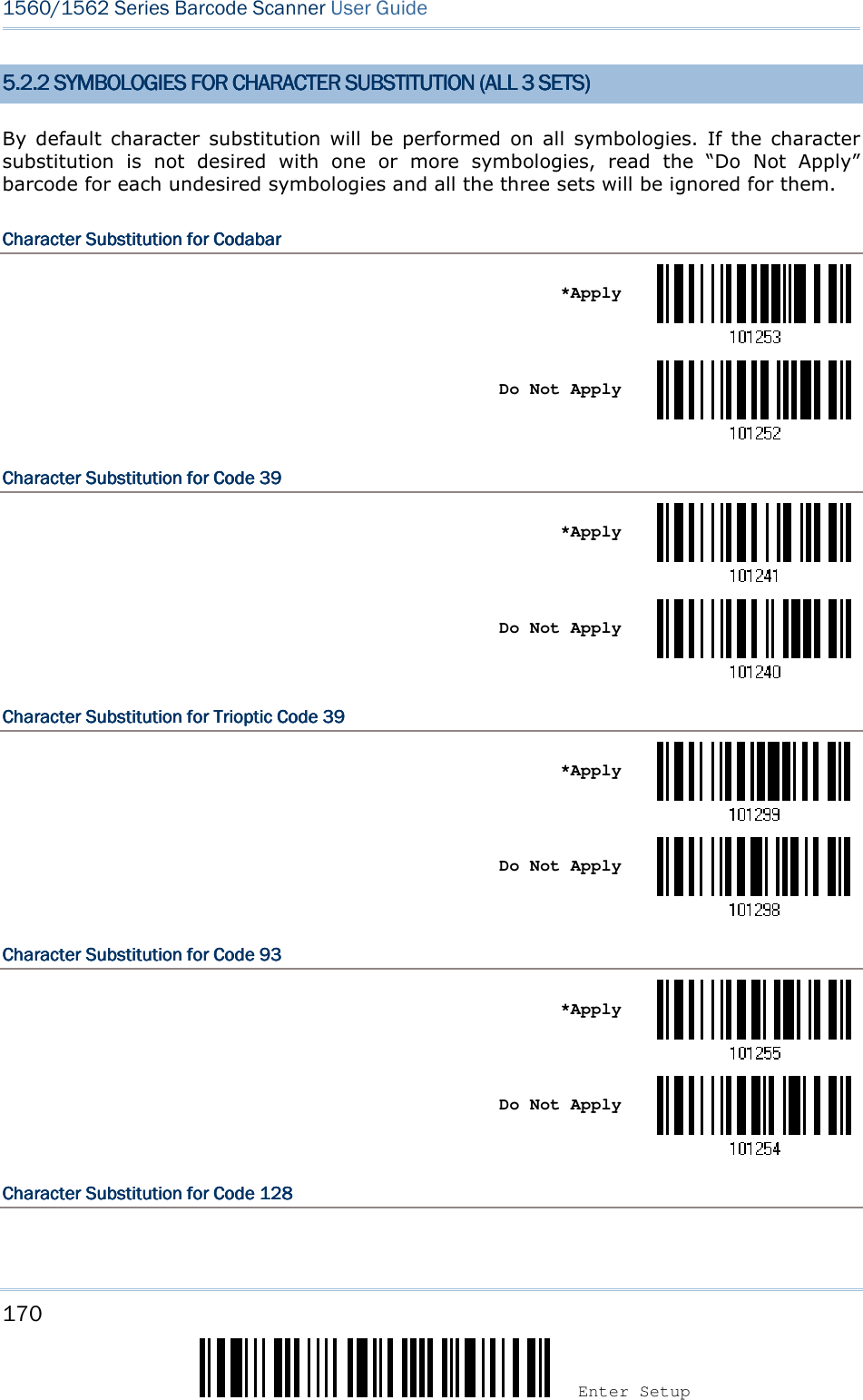
![171 Update Chapter 5 ! ! ! ! [[[[] ] ] ] Heading 1 Heading 1 Heading 1 Heading 1 *Apply Do Not Apply Character SubstitutionCharacter SubstitutionCharacter SubstitutionCharacter Substitution for for for for GS1GS1GS1GS1----128128128128 *Apply Do Not Apply Character SubstitutionCharacter SubstitutionCharacter SubstitutionCharacter Substitution for for for for ISBT 128ISBT 128ISBT 128ISBT 128 *Apply Do Not Apply Character SubstitutionCharacter SubstitutionCharacter SubstitutionCharacter Substitution fofofofor r r r EANEANEANEAN----8 (No Addon)8 (No Addon)8 (No Addon)8 (No Addon) *Apply Do Not Apply Character SubstitutionCharacter SubstitutionCharacter SubstitutionCharacter Substitution for for for for EANEANEANEAN----8 Addon 28 Addon 28 Addon 28 Addon 2 *Apply Do Not Apply Character SubstitutionCharacter SubstitutionCharacter SubstitutionCharacter Substitution for for for for EANEANEANEAN----8 Addon 58 Addon 58 Addon 58 Addon 5](https://usermanual.wiki/CipherLab/3656CRADLE/User-Guide-3879656-Page-189.png)
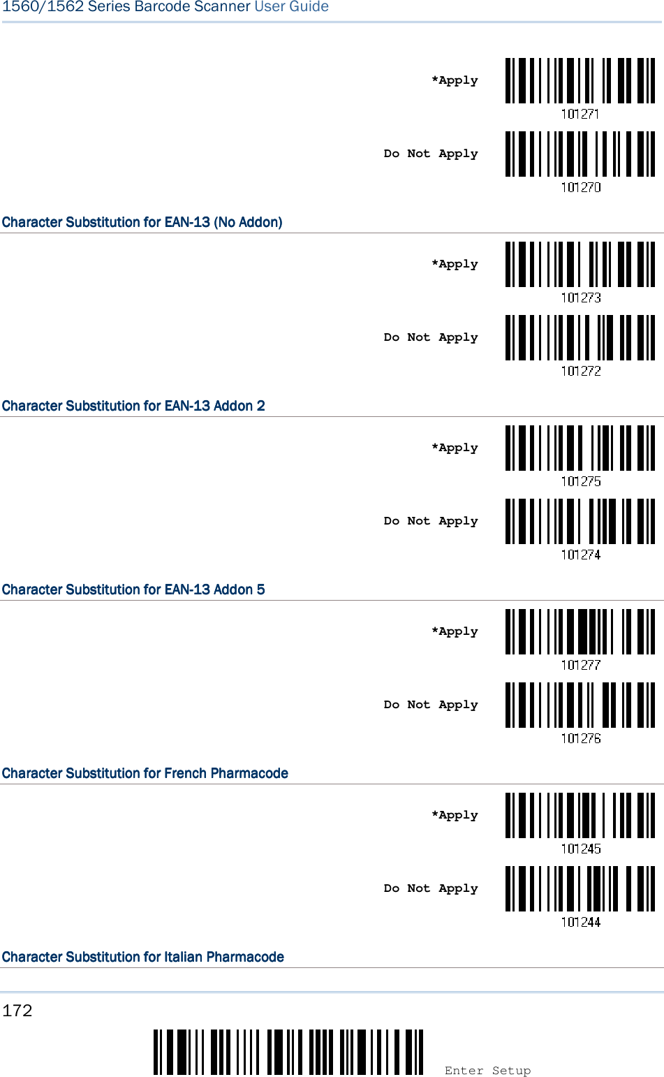
![173 Update Chapter 5 ! ! ! ! [[[[] ] ] ] Heading 1 Heading 1 Heading 1 Heading 1 *Apply Do Not Apply Character SubstitutionCharacter SubstitutionCharacter SubstitutionCharacter Substitution for for for for Industrial 25Industrial 25Industrial 25Industrial 25 *Apply Do Not Apply Character SubstitutionCharacter SubstitutionCharacter SubstitutionCharacter Substitution for for for for Interleaved 25Interleaved 25Interleaved 25Interleaved 25 *Apply Do Not Apply Character SubstitutionCharacter SubstitutionCharacter SubstitutionCharacter Substitution for for for for Matrix Matrix Matrix Matrix 25252525 *Apply Do Not Apply Character SubstitutionCharacter SubstitutionCharacter SubstitutionCharacter Substitution for for for for MSIMSIMSIMSI *Apply Do Not Apply Character SubstitutionCharacter SubstitutionCharacter SubstitutionCharacter Substitution for for for for PlesseyPlesseyPlesseyPlessey](https://usermanual.wiki/CipherLab/3656CRADLE/User-Guide-3879656-Page-191.png)
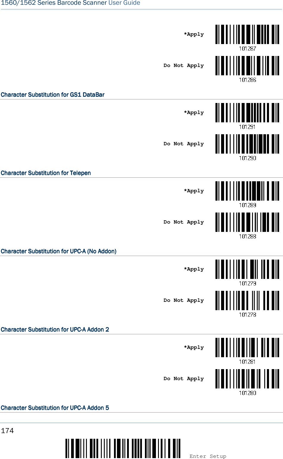
![175 Update Chapter 5 ! ! ! ! [[[[] ] ] ] Heading 1 Heading 1 Heading 1 Heading 1 *Apply Do Not Apply Character SubstitutionCharacter SubstitutionCharacter SubstitutionCharacter Substitution for for for for UPCUPCUPCUPC----E E E E (No Addon(No Addon(No Addon(No Addon)))) *Apply Do Not Apply Character SubstitutionCharacter SubstitutionCharacter SubstitutionCharacter Substitution for for for for UPCUPCUPCUPC----E Addon 2E Addon 2E Addon 2E Addon 2 *Apply Do Not Apply Character SubstitutionCharacter SubstitutionCharacter SubstitutionCharacter Substitution for for for for UPCUPCUPCUPC----E Addon 5E Addon 5E Addon 5E Addon 5 *Apply Do Not Apply Character Character Character Character SubstitutionSubstitutionSubstitutionSubstitution for Code 11for Code 11for Code 11for Code 11 *Apply Do Not Apply](https://usermanual.wiki/CipherLab/3656CRADLE/User-Guide-3879656-Page-193.png)
![176 Enter Setup 1560/1562 Series Barcode Scanner User Guide 5.3 PREFIX/SUFFIX CO5.3 PREFIX/SUFFIX CO5.3 PREFIX/SUFFIX CO5.3 PREFIX/SUFFIX CODEDEDEDE By default, there is no prefix code, and [ENTER] or [CR] (Carriage Return) is configured to be suffix code. Up to 8 characters can be configured, for example, “Barcode_”, and you will have the string appear in front of the barcode read, like this – “Barcode_1234567890”. If “BT HID”, “USB HID” or “Keyboard Wedge” is configured for interface, Key Type and Key Status will then become applicable. You may decide whether or not to apply Key Status when “Normal Key” is selected for Key Type. Key TypeKey TypeKey TypeKey Type Key StatusKey StatusKey StatusKey Status Scan Code Up to 4 scan code values are allowed. N/A Normal Key Up to 8 character strings are allowed. Add Shift Add Left Ctrl Add Left Alt Add Right Ctrl Add Right Alt Refer to Keyboard Wedge Table. Configure Prefix Configure Suffix 1) Read the barcode above to apply prefix code or suffix code separately, and follow steps 2~3. (Max. 8 characters each) 2) Read the “Hexadecimal Value” barcode on page 242 for the desired character string. For example, read “2” and “B” for the scanner to prefix or suffix the character [+]. 3) Read the “Validate” barcode to complete this setting.](https://usermanual.wiki/CipherLab/3656CRADLE/User-Guide-3879656-Page-194.png)
![177 Update Chapter 5 ! ! ! ! [[[[] ] ] ] Heading 1 Heading 1 Heading 1 Heading 1 5.4 CODE ID5.4 CODE ID5.4 CODE ID5.4 CODE ID Up to two characters for Code ID can be configured for each symbology. To make the Code ID configuration easier, the scanner provides five pre-defined Code ID sets that you can select one and make necessary changes on it. If “BT HID”, “USB HID” or “Keyboard Wedge” is configured for interface, Key Type and Key Status will then become applicable. You may decide whether or not to apply Key Status when “Normal Key” is selected for Key Type. Key TypeKey TypeKey TypeKey Type Key StatusKey StatusKey StatusKey Status Scan Code Only 1 scan code value is allowed. N/A Normal Key Up to 2 character strings are allowed. Add Shift Add Left Ctrl Add Left Alt Add Right Ctrl Add Right Alt Refer to Keyboard Wedge Table. Note: "]C1" is the Code ID of GS1-128 (EAN-128) barcodes; "]e0" is the default Code ID of GS1 DataBar (RSS) barcodes. 5.4.5.4.5.4.5.4.1111 SELECT PRESELECT PRESELECT PRESELECT PRE----DEFINED CODE IDDEFINED CODE IDDEFINED CODE IDDEFINED CODE ID Apply Code ID Set 1 Apply Code ID Set 2 Apply Code ID Set 3 Apply Code ID Set 4 Apply Code ID Set 5](https://usermanual.wiki/CipherLab/3656CRADLE/User-Guide-3879656-Page-195.png)
![178 Enter Setup 1560/1562 Series Barcode Scanner User Guide Code ID optionsCode ID optionsCode ID optionsCode ID options Set 1Set 1Set 1Set 1 Set 2Set 2Set 2Set 2 Set 3Set 3Set 3Set 3 Set 4Set 4Set 4Set 4 Set 5Set 5Set 5Set 5 Code 39 A C Y M A Trioptic Code 39 A C Y M X Italian Pharmacode A C Y M A French Pharmacode A C Y M A Industrial 25 C H H H S Interleaved 25 D I Z I S Matrix 25 E G G G S Codabar F N X N F Code 93 I L L L G Code 128 H K K K C ISBT 128 H K K K C UPC-E S E C E E EAN-8 P B B FF E EAN-13 M A A F E UPC-A J A A A E MSI V V D P M Plessey W W E Q P Telepen Z --- --- --- --- Code 11 K J J D H Besides Set 1 ~ 5 of Code ID options, you can also scan the barcode below to apply AIM Code ID as the Code ID option. Apply AIM Code ID After applying AIM Code ID, three characters are added in front of the output data. “]” is always the first character. The second (Character) and third (Modifier Character) may vary depending on symbologies. Please refer to the table below. SymbologySymbologySymbologySymbology CharacterCharacterCharacterCharacter Modifier CharacterModifier CharacterModifier CharacterModifier Character Codabar F 0: Standard Codabar symbol. No special processing. Code 11 H 0: Single modulo 11 check character validated and transmitted 1: Two modulo 11 check characters validated and transmitted 3: Check characters validated but not transmitted](https://usermanual.wiki/CipherLab/3656CRADLE/User-Guide-3879656-Page-196.png)
![179 Update Chapter 5 ! ! ! ! [[[[] ] ] ] Heading 1 Heading 1 Heading 1 Heading 1 Code 39 A 0: No check character validation nor full ASCII processing. All data transmitted as decoded. 1: Modulo 43 check character validated and transmitted 3: Modulo 43 check character validated but not transmitted 4: Full ASCII character conversion performed. No check character validation. 5: Full ASCII character conversion performed. Modulo 43 check character validated and transmitted. 7: Full ASCII character conversion performed. Modulo 43 check character validated but not transmitted. Code 93 G No options specified. Always transmit 0. Code 128 C 0: Standard data packet. No FNC1 in first or second symbol character position after start character. 1: EAN/UCC-128 data packet. FNC1 in first symbol character position after start character. 2: FNC1 in second symbol character position after start character. 4: Concatenation according to International Society for Blood Transfusion specifications has been performed. Concatenated data follows. GS1 DataBar Family e No option specified at this time. Always transmit 0. GS1 DataBar and GS1 DataBar Limited transmit with an Application Identifier “01”. Interleaved 25 I 0: No check character validation 1: Modulo 10 symbol check character validated and transmitted 3: Modulo 10 symbol check character validated but not transmitted MSI M 0: Modulo 10 symbol check character validated and transmitted 1: Modulo 10 symbol check character validated but not transmitted Matrix 25 X No options specified. Always transmit 0. Plessey P No options specified. Always transmit 0. Industrial 25 S No options specified. Always transmit 0. Telepen B No options specified. Always transmit 0. UPC/EAN E 0: Standard data packet in full EAN format (13 digits for EAN-13, UPC-A, and UPC-E; does not include add-on data) 3: Combined data packet comprising 13 digits from EAN-13, UPC-A, or UPC-E symbol and 2 or 5 digits from add-on symbol 4: EAN-8 data packet](https://usermanual.wiki/CipherLab/3656CRADLE/User-Guide-3879656-Page-197.png)
![180 Enter Setup 1560/1562 Series Barcode Scanner User Guide 5.4.25.4.25.4.25.4.2 CHANGE CODE IDCHANGE CODE IDCHANGE CODE IDCHANGE CODE ID 1) Read the barcode below to change code ID of a specific symbology. 2) Read the “Hexadecimal Value” barcode on page 242 for the desired character string. For example, read “4” and “4” for applying the character [D] for Code ID. 3) Read the “Validate” barcode to complete this setting. Configure Code ID for Codabar Configure Code ID for Code 39 Configure Code ID for Trioptic Code 39 Configure Code ID for Code 93 Configure Code ID for Code 128 Configure Code ID for ISBT 128 Configure Code ID for EAN-8 Configure Code ID for EAN-13 Configure Code ID for French Pharmacode Configure Code ID for Italian Pharmacode](https://usermanual.wiki/CipherLab/3656CRADLE/User-Guide-3879656-Page-198.png)
![181 Update Chapter 5 ! ! ! ! [[[[] ] ] ] Heading 1 Heading 1 Heading 1 Heading 1 Configure Code ID for Industrial 25 Configure Code ID for Interleaved 25 Configure Code ID for Matrix 25 Configure Code ID for MSI Configure Code ID for Plessey Configure Code ID for Telepen Configure Code ID for UPC-A Configure Code ID for UPC-E Configure Code ID for Code 11 5.4.3 CLEAR CODE ID 5.4.3 CLEAR CODE ID 5.4.3 CLEAR CODE ID 5.4.3 CLEAR CODE ID SETTINGSSETTINGSSETTINGSSETTINGS Clear All Code ID Settings](https://usermanual.wiki/CipherLab/3656CRADLE/User-Guide-3879656-Page-199.png)
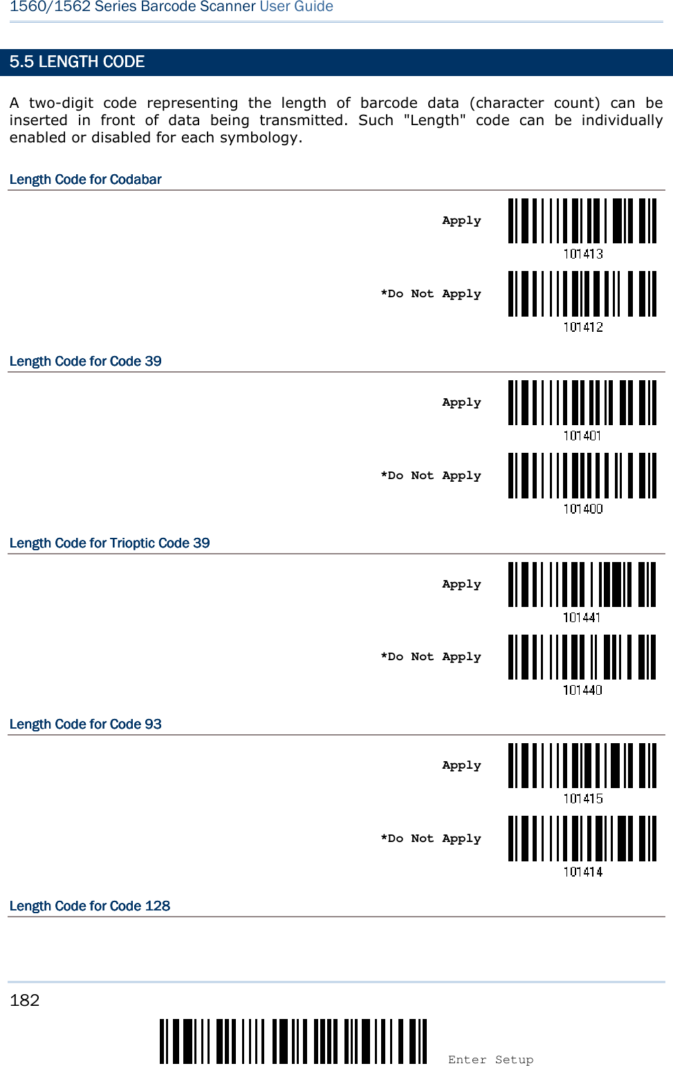
![183 Update Chapter 5 ! ! ! ! [[[[] ] ] ] Heading 1 Heading 1 Heading 1 Heading 1 Apply *Do Not Apply Length CodeLength CodeLength CodeLength Code for for for for GS1GS1GS1GS1----128 128 128 128 & GS1 DataBa& GS1 DataBa& GS1 DataBa& GS1 DataBarrrr Apply *Do Not Apply Length CodeLength CodeLength CodeLength Code for for for for ISBT 128ISBT 128ISBT 128ISBT 128 Apply *Do Not Apply Length CodeLength CodeLength CodeLength Code for for for for EANEANEANEAN----8888 Apply *Do Not Apply Length CodeLength CodeLength CodeLength Code for for for for EANEANEANEAN----13131313 Apply *Do Not Apply](https://usermanual.wiki/CipherLab/3656CRADLE/User-Guide-3879656-Page-201.png)
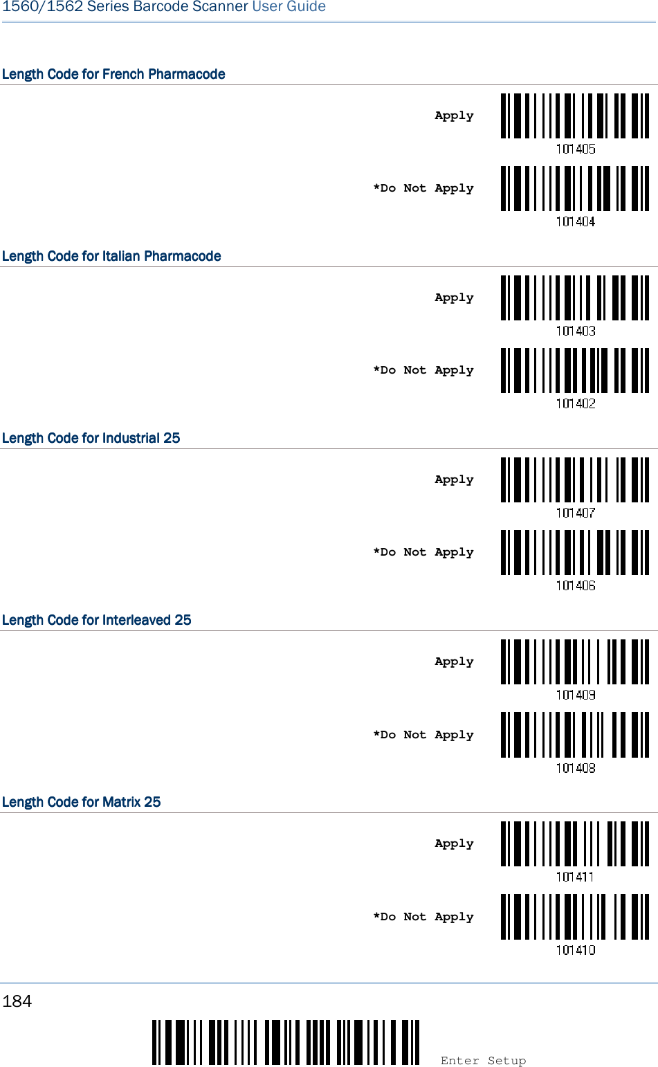
![185 Update Chapter 5 ! ! ! ! [[[[] ] ] ] Heading 1 Heading 1 Heading 1 Heading 1 Length CodeLength CodeLength CodeLength Code for for for for MSIMSIMSIMSI Apply *Do Not Apply Length CodeLength CodeLength CodeLength Code for for for for PlesseyPlesseyPlesseyPlessey Apply *Do Not Apply Length CodeLength CodeLength CodeLength Code for for for for TelepenTelepenTelepenTelepen Apply *Do Not Apply Length CodeLength CodeLength CodeLength Code for for for for UPCUPCUPCUPC----AAAA Apply *Do Not Apply Length CodeLength CodeLength CodeLength Code for for for for UPCUPCUPCUPC----EEEE Apply *Do Not Apply](https://usermanual.wiki/CipherLab/3656CRADLE/User-Guide-3879656-Page-203.png)
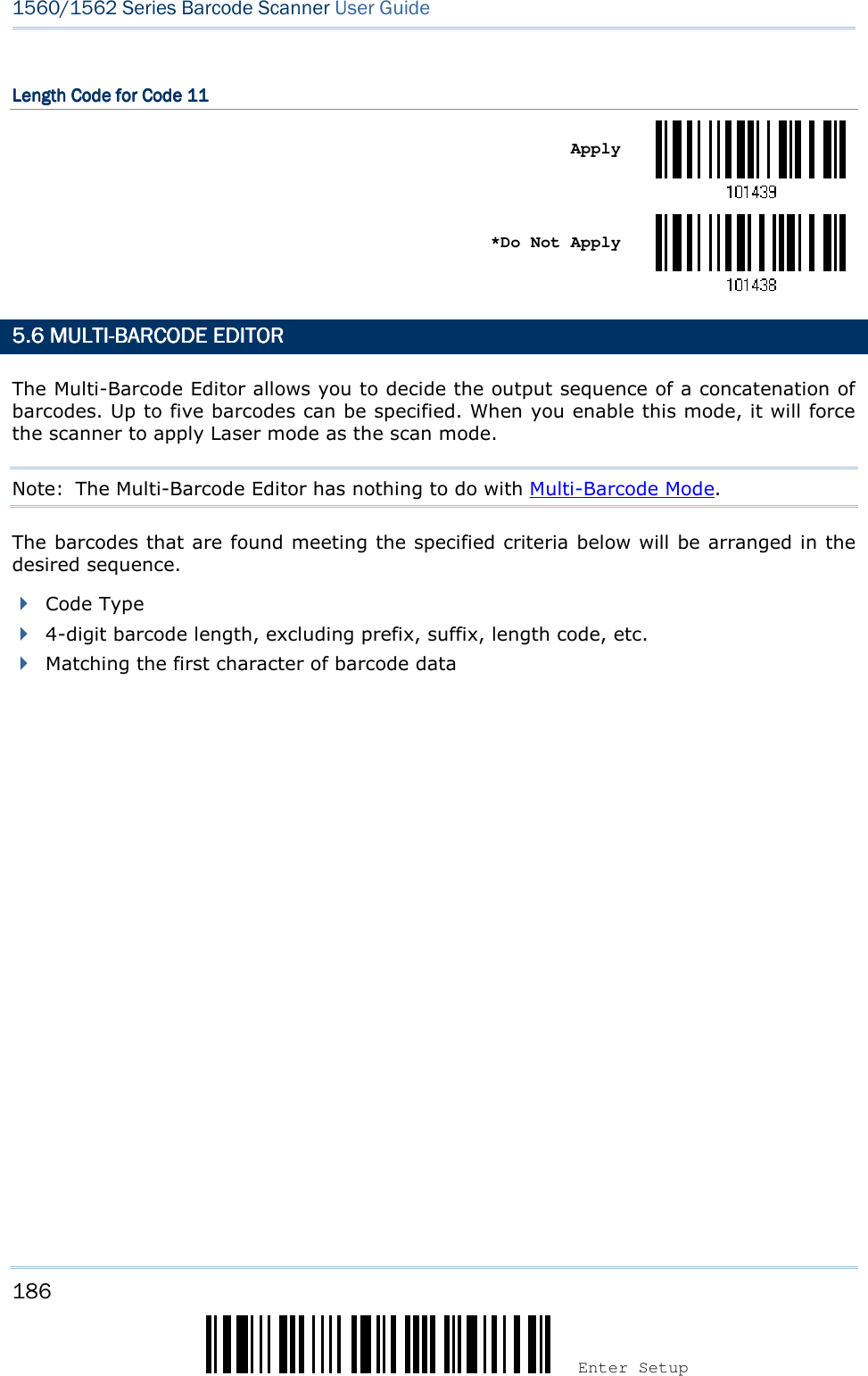
![187 Update Chapter 5 ! ! ! ! [[[[] ] ] ] Heading 1 Heading 1 Heading 1 Heading 1 5.6.1 EDIT A CONCATE5.6.1 EDIT A CONCATE5.6.1 EDIT A CONCATE5.6.1 EDIT A CONCATENATION OF BARCODESNATION OF BARCODESNATION OF BARCODESNATION OF BARCODES Edit Output Sequence 1) Read the barcode above to start editing a concatenation of barcodes. 2) Code Type setting – read the “Hexadecimal Value” barcode on page 242 for Code Type of the (first) barcode. For example, read “4” and “1” for Code 39.](https://usermanual.wiki/CipherLab/3656CRADLE/User-Guide-3879656-Page-205.png)
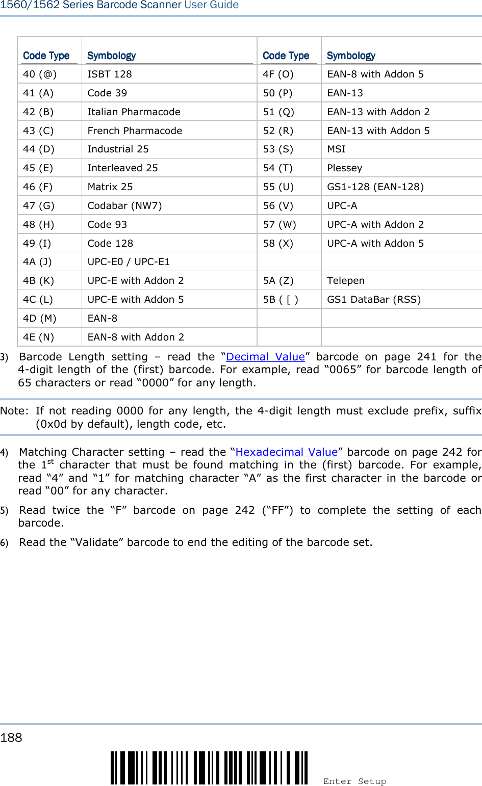
![189 Update Chapter 5 ! ! ! ! [[[[] ] ] ] Heading 1 Heading 1 Heading 1 Heading 1 5.6.2 ACTIVATE THE C5.6.2 ACTIVATE THE C5.6.2 ACTIVATE THE C5.6.2 ACTIVATE THE CONCATENATION OF BARCONCATENATION OF BARCONCATENATION OF BARCONCATENATION OF BARCODESODESODESODES By default, the output sequence editing of the concatenation of barcodes is not applied. When “Enforce Output Sequence” is enabled, all barcodes read by the scanner must meet with the criteria for the concatenation. If data is found excluded from all output sequence sets (= not meeting with the criteria), the scanner will not accept the reading, and therefore, data will not be transmitted. When “Apply Output Sequence” is enabled, only barcodes found meeting with the criteria are counted for the concatenation. Those found not meeting with the criteria are processed normally and individually. Note: When it requires reading more barcodes to complete the “output sequence” requirements, the scanner will respond with one short beep (low tone). After reading an acceptable barcode, its LED indicator will become solid green and go off quickly (= Good Read). Upon completion of reading acceptable barcodes, the scanner will respond with one short beep (high tone) and its LED indicator will become solid green and go off quickly (= Good Read). *Ignore Output Sequence Enforce Output Sequence Apply Output Sequence Warning: When you disable the Multi-Barcode Editor later, the scan mode remains unchanged. If Laser mode is not desired, proceed to select a scan mode best suits your application.](https://usermanual.wiki/CipherLab/3656CRADLE/User-Guide-3879656-Page-207.png)
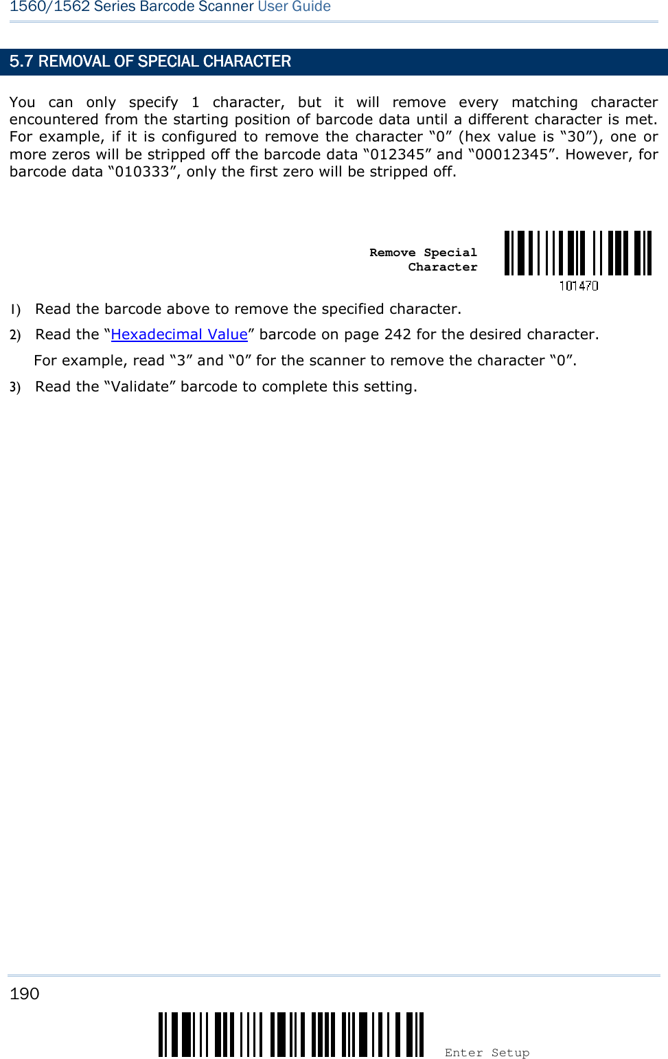
![191 Update The scanner allows advanced data editing by applying user-configured editing formats. The whole processed data can be divided into fields by user-specified rules. These fields together with the user-configurable additional fields consist of the data actually sent to the host computer. [Prefix Code] [Code ID] [Length Code] [Data] [Suffix Code] Additional Field(s) None by default None by default None by default Barcode itself 0x0d by default IN THIS CHAPTERIN THIS CHAPTERIN THIS CHAPTERIN THIS CHAPTER 6.1 Activating Editing Formats ......................................... 192 6.2 How to Configure Editing Formats ............................... 194 6.3 Configuring Format — Define Data Criteria ................... 197 6.4 Configuring Format — Define Data Field ....................... 205 6.5 Configuring Format — Define Transmission Sequence .... 214 6.6 Programming Examples ............................................. 216 Chapter Chapter Chapter Chapter 6666 APPLYING FORMATS FORAPPLYING FORMATS FORAPPLYING FORMATS FORAPPLYING FORMATS FOR DADADADATA EDITINGTA EDITINGTA EDITINGTA EDITING](https://usermanual.wiki/CipherLab/3656CRADLE/User-Guide-3879656-Page-209.png)
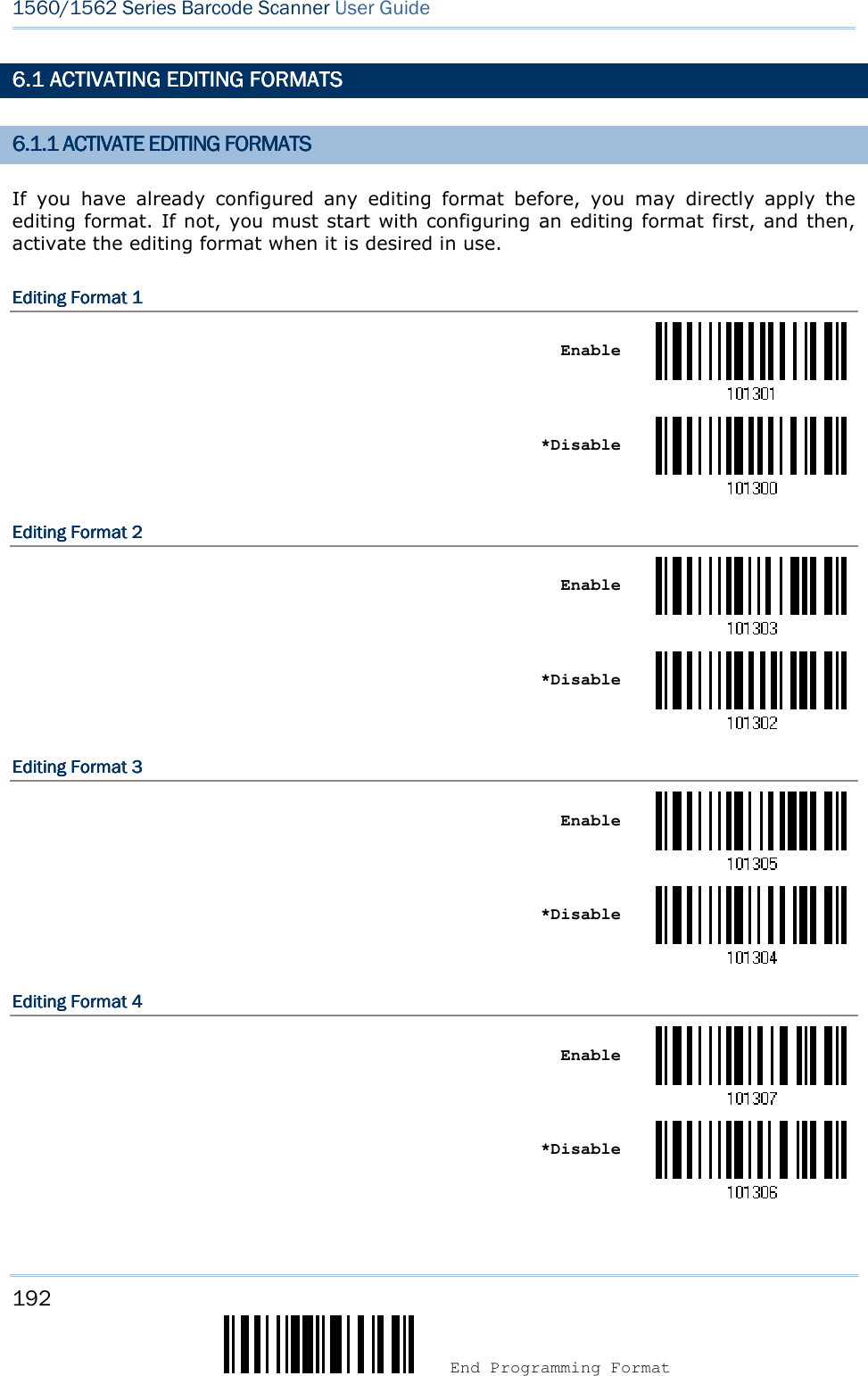
![193 Update Chapter 6 ! ! ! ! [[[[] ] ] ] Heading 1 Heading 1 Heading 1 Heading 1 Editing Format 5Editing Format 5Editing Format 5Editing Format 5 Enable *Disable 6.1.2 6.1.2 6.1.2 6.1.2 EXCLUSIVE DATA EDITIEXCLUSIVE DATA EDITIEXCLUSIVE DATA EDITIEXCLUSIVE DATA EDITINGNGNGNG By default, only barcodes found meeting with the criteria are processed by the editing formats. Those found not meeting with the criteria are processed normally. When “Exclusive Data Editing” is enabled, all barcodes read by the scanner must be processed by the editing formats. If data is found excluded from all enabled editing formats (= not meeting with the specified criteria), the scanner will not accept the reading, and therefore, data will not be transmitted. Yes *No](https://usermanual.wiki/CipherLab/3656CRADLE/User-Guide-3879656-Page-211.png)
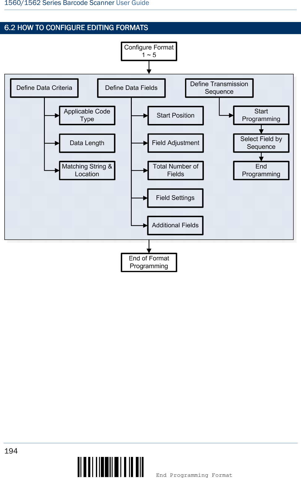
![195 Update Chapter 6 ! ! ! ! [[[[] ] ] ] Heading 1 Heading 1 Heading 1 Heading 1 6.2.1 SELECT FORMAT 6.2.1 SELECT FORMAT 6.2.1 SELECT FORMAT 6.2.1 SELECT FORMAT TO CONFIGURETO CONFIGURETO CONFIGURETO CONFIGURE Start Programming FormatStart Programming FormatStart Programming FormatStart Programming Format Select one editing format (Format 1~5) and the parameters pertaining to the editing format can then be configured – applicable code type, data length, matching string & location, start position, field adjustment, total number of fields, field settings (field-dividing rule), additional fields, and field transmission sequence. Up to five different formats can be specified. Configure Format 1 Configure Format 2 Configure Format 3 Configure Format 4 Configure Format 5 Note: Before you complete the programming of an editing format, if you have the scanner read any barcode for parameters other than those pertaining to the editing format, it will automatically abort the programming process. End Programming FormatEnd Programming FormatEnd Programming FormatEnd Programming Format After having configured all the desired parameters, you must have the scanner read the “End Programming Format” barcode, which can be located at the bottom of every even page in this chapter. End Programming Format](https://usermanual.wiki/CipherLab/3656CRADLE/User-Guide-3879656-Page-213.png)
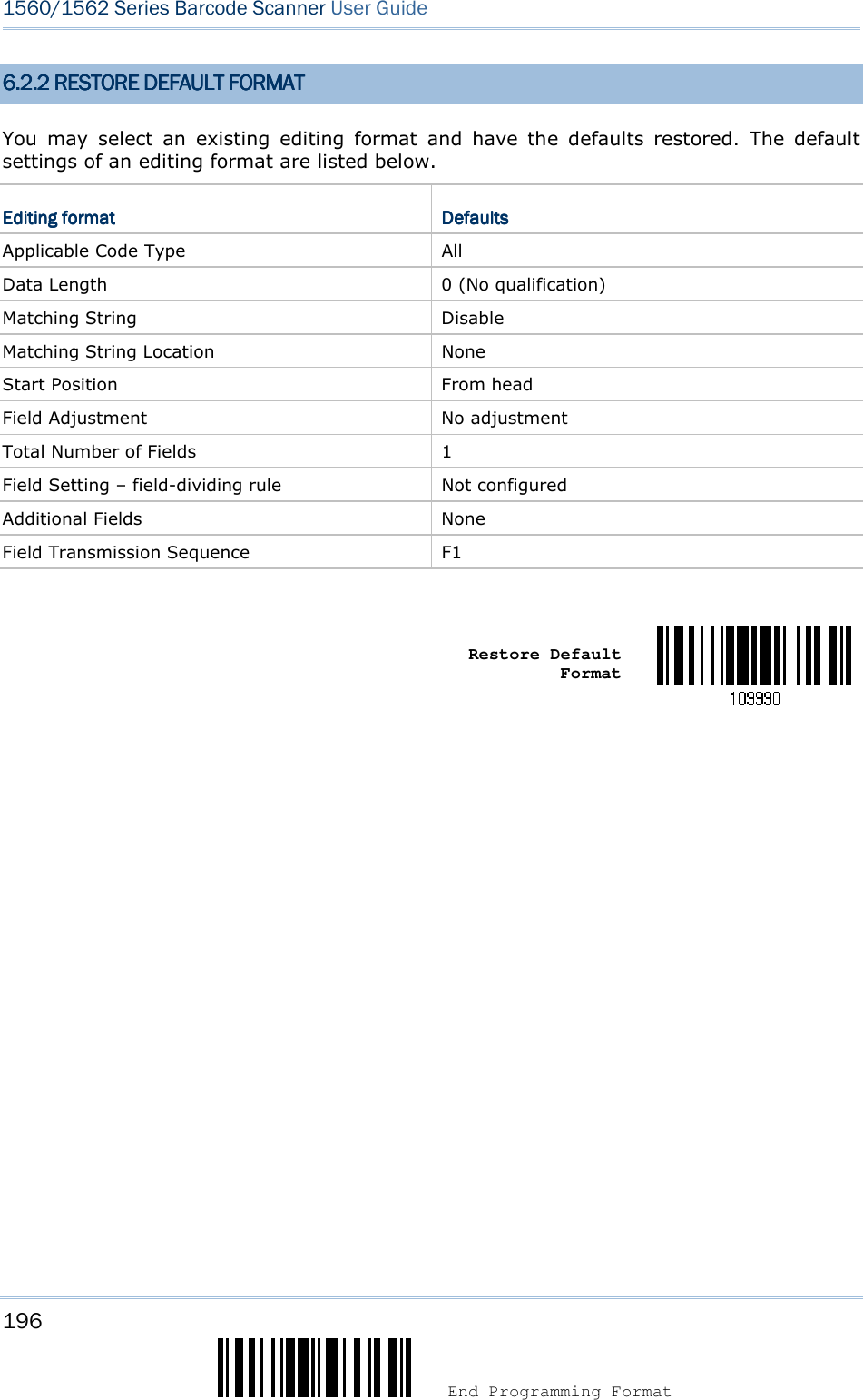
![197 Update Chapter 6 ! ! ! ! [[[[] ] ] ] Heading 1 Heading 1 Heading 1 Heading 1 6.3 CONFIGURING FORM6.3 CONFIGURING FORM6.3 CONFIGURING FORM6.3 CONFIGURING FORMAT AT AT AT ———— DEFINE DATADEFINE DATADEFINE DATADEFINE DATA CRITERIACRITERIACRITERIACRITERIA Three applicable conditions can be configured to check whether the data read by the scanner can be processed by the particular editing format. Note: Data editing cannot be performed unless the three conditions are all met. 6.3.1 APPLICABLE COD6.3.1 APPLICABLE COD6.3.1 APPLICABLE COD6.3.1 APPLICABLE CODE E E E TYPETYPETYPETYPE By default, barcodes of all the supported symbologies will be processed by any editing format, if having been configured and enabled. For quick configuration, you may first clear all, and then select the desired symbologies. Note: You must have at least one symbology selected. *Apply to All Clear All](https://usermanual.wiki/CipherLab/3656CRADLE/User-Guide-3879656-Page-215.png)
![199 Update Chapter 6 ! ! ! ! [[[[] ] ] ] Heading 1 Heading 1 Heading 1 Heading 1 Editing Format for Editing Format for Editing Format for Editing Format for GS1GS1GS1GS1----128 128 128 128 & GS1 DataBar& GS1 DataBar& GS1 DataBar& GS1 DataBar *Apply Do Not Apply Editing Format for Editing Format for Editing Format for Editing Format for ISBT 128ISBT 128ISBT 128ISBT 128 *Apply Do Not Apply EdiEdiEdiEditing Format for EANting Format for EANting Format for EANting Format for EAN----8888 *Apply Do Not Apply Editing Format for EANEditing Format for EANEditing Format for EANEditing Format for EAN----8 Addon 28 Addon 28 Addon 28 Addon 2 *Apply Do Not Apply Editing Format for EANEditing Format for EANEditing Format for EANEditing Format for EAN----8 Addon 58 Addon 58 Addon 58 Addon 5 *Apply Do Not Apply](https://usermanual.wiki/CipherLab/3656CRADLE/User-Guide-3879656-Page-217.png)
![201 Update Chapter 6 ! ! ! ! [[[[] ] ] ] Heading 1 Heading 1 Heading 1 Heading 1 Editing Format for Industrial 25Editing Format for Industrial 25Editing Format for Industrial 25Editing Format for Industrial 25 *Apply Do Not Apply Editing Format for Interleaved 25Editing Format for Interleaved 25Editing Format for Interleaved 25Editing Format for Interleaved 25 *Apply Do Not Apply Editing Format for Matrix 25Editing Format for Matrix 25Editing Format for Matrix 25Editing Format for Matrix 25 *Apply Do Not Apply Editing Format for MSIEditing Format for MSIEditing Format for MSIEditing Format for MSI *Apply Do Not Apply Editing Format for PlesseyEditing Format for PlesseyEditing Format for PlesseyEditing Format for Plessey *Apply Do Not Apply](https://usermanual.wiki/CipherLab/3656CRADLE/User-Guide-3879656-Page-219.png)
![203 Update Chapter 6 ! ! ! ! [[[[] ] ] ] Heading 1 Heading 1 Heading 1 Heading 1 Editing Format for UPCEditing Format for UPCEditing Format for UPCEditing Format for UPC----E Addon 2E Addon 2E Addon 2E Addon 2 *Apply Do Not Apply Editing Format for UPCEditing Format for UPCEditing Format for UPCEditing Format for UPC----E Addon 5E Addon 5E Addon 5E Addon 5 *Apply Do Not Apply Editing Editing Editing Editing Format for Format for Format for Format for Code 11Code 11Code 11Code 11 *Apply Do Not Apply](https://usermanual.wiki/CipherLab/3656CRADLE/User-Guide-3879656-Page-221.png)
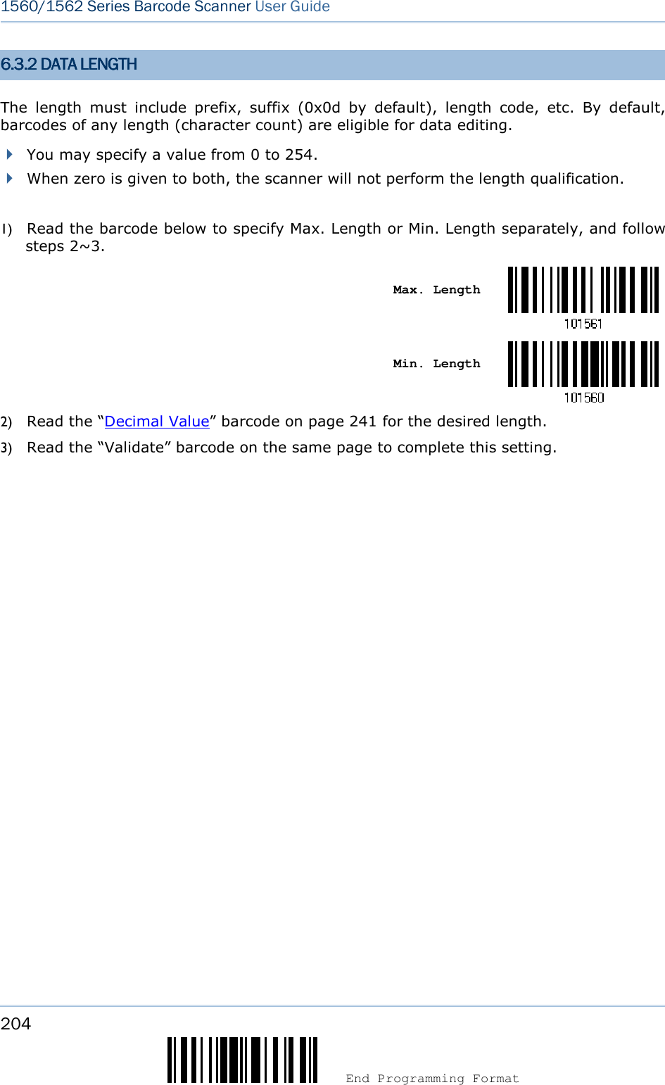
![205 Update Chapter 6 ! ! ! ! [[[[] ] ] ] Heading 1 Heading 1 Heading 1 Heading 1 6.3.3 MATCHING STRIN6.3.3 MATCHING STRIN6.3.3 MATCHING STRIN6.3.3 MATCHING STRING & LOCATIONG & LOCATIONG & LOCATIONG & LOCATION By default, no matching string is specified, and therefore, it is disabled. You may enable this feature by specifying a matching string; up to four characters are allowed. When the Matching String Location is zero, the scanner will only check for the existence of the matching string in the barcode data. You may specify a value from 1 to 254 to indicate where the matching string starts in the barcode data. 1) Read the barcode to specify a matching string. Matching String… 2) Read the “Hexadecimal Value” barcode on page 242 for the desired character string. 3) Read the “Validate” barcode to complete this setting. 4) Read the barcode to specify the location of the matching string. Location of Matching String… 5) Read the “Decimal Value” barcode on page 241 for the desired location. 6) Read the “Validate” barcode on the same page to complete this setting. 6.4 CONFIGURING FORM6.4 CONFIGURING FORM6.4 CONFIGURING FORM6.4 CONFIGURING FORMAT AT AT AT ———— DEFINE DADEFINE DADEFINE DADEFINE DATA TA TA TA FIELDFIELDFIELDFIELD 6666....4.14.14.14.1 START POSITIONSTART POSITIONSTART POSITIONSTART POSITION Data can be divided into fields in one of the following direction – from head (F1) to tail (F5) from tail (F1) to head (F5) *From Head From Tail](https://usermanual.wiki/CipherLab/3656CRADLE/User-Guide-3879656-Page-223.png)
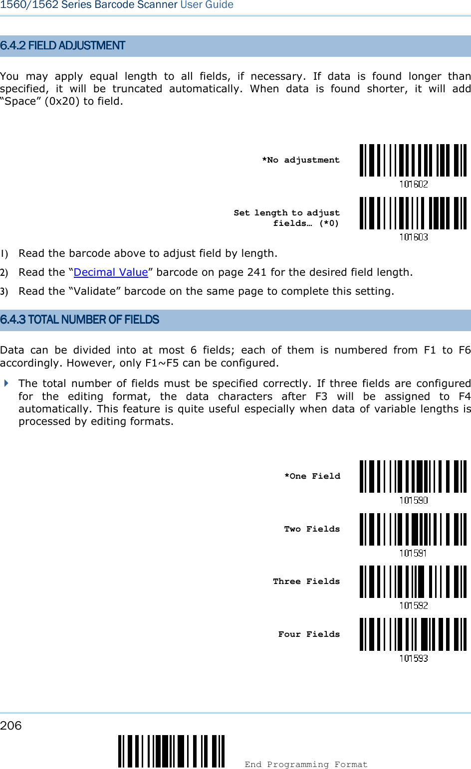
![207 Update Chapter 6 ! ! ! ! [[[[] ] ] ] HeaHeaHeaHeading 1 ding 1 ding 1 ding 1 Five Fields Six Fields Note: The number of configurable fields is always one less than the total number of fields specified. The extra data characters beyond the last field configured will be automatically assigned to the next field. 6.6.6.6.4.44.44.44.4 FIELD SETTINGSFIELD SETTINGSFIELD SETTINGSFIELD SETTINGS Data eligible for editing formats is divided into fields by user-specified rules – either using the field terminating string or specified field length. By Terminating StringBy Terminating StringBy Terminating StringBy Terminating String Specify the field terminating string. Up to two characters are allowed. The scanner will search for the occurrence of this particular string in the data. By default, this string will be included in the field. You may discard it. By LengthBy LengthBy LengthBy Length Alternatively, you may simply specify the field length. The scanner will assign the next specified number of characters into the field. Field 1Field 1Field 1Field 1 SettingSettingSettingSetting 1. Read the barcode below to divide field 1 by a specified terminating string. Select Field Separator to Divide Field 1… 2. Read the “Hexadecimal Value” barcode on page 242 for the desired character string. 3. Read the “Validate” barcode to complete this setting. 4. Read the “Discard Separator” barcode if the field separator is not desired in the field. *Include Separator Discard Separator](https://usermanual.wiki/CipherLab/3656CRADLE/User-Guide-3879656-Page-225.png)
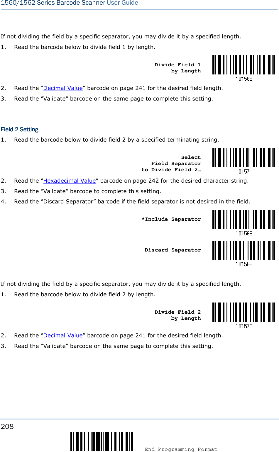
![209 Update Chapter 6 ! ! ! ! [[[[] ] ] ] Heading 1 Heading 1 Heading 1 Heading 1 Field 3Field 3Field 3Field 3 SettingSettingSettingSetting 1. Read the barcode below to divide field 3 by a specified terminating string. Select Field Separator to Divide Field 3… 2. Read the “Hexadecimal Value” barcode on page 242 for the desired character string. 3. Read the “Validate” barcode to complete this setting. 4. Read the “Discard Separator” barcode if the field separator is not desired in the field. *Include Separator Discard Separator If not dividing the field by a specific separator, you may divide it by a specified length. 1. Read the barcode below to divide field 3 by length. Divide Field 3 by Length 2. Read the “Decimal Value” barcode on page 241 for the desired field length. 3. Read the “Validate” barcode on the same page to complete this setting.](https://usermanual.wiki/CipherLab/3656CRADLE/User-Guide-3879656-Page-227.png)
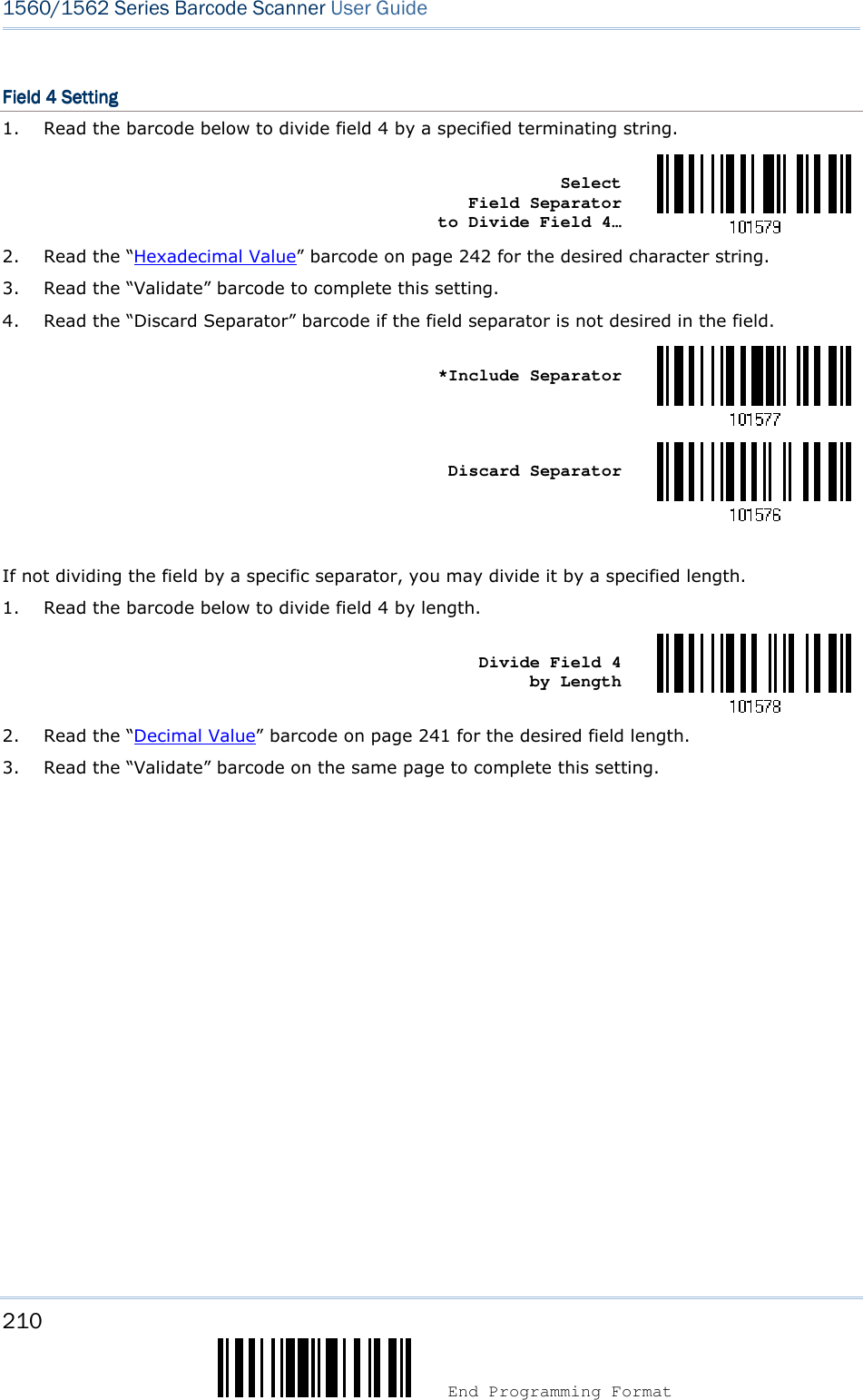
![211 Update Chapter 6 ! ! ! ! [[[[] ] ] ] Heading 1 Heading 1 Heading 1 Heading 1 Field 5Field 5Field 5Field 5 SettingSettingSettingSetting 1. Read the barcode below to divide field 5 by a specified terminating string. Select Field Separator to Divide Field 5… 2. Read the “Hexadecimal Value” barcode on page 242 for the desired character string. 3. Read the “Validate” barcode to complete this setting. 4. Read the “Discard Separator” barcode if the field separator is not desired in the field. *Include Separator Discard Separator If not dividing the field by a specific separator, you may divide it by a specified length. 1. Read the barcode below to divide field 5 by length. Divide Field 5 by Length 2. Read the “Decimal Value” barcode on page 241 for the desired field length. 3. Read the “Validate” barcode on the same page to complete this setting.](https://usermanual.wiki/CipherLab/3656CRADLE/User-Guide-3879656-Page-229.png)
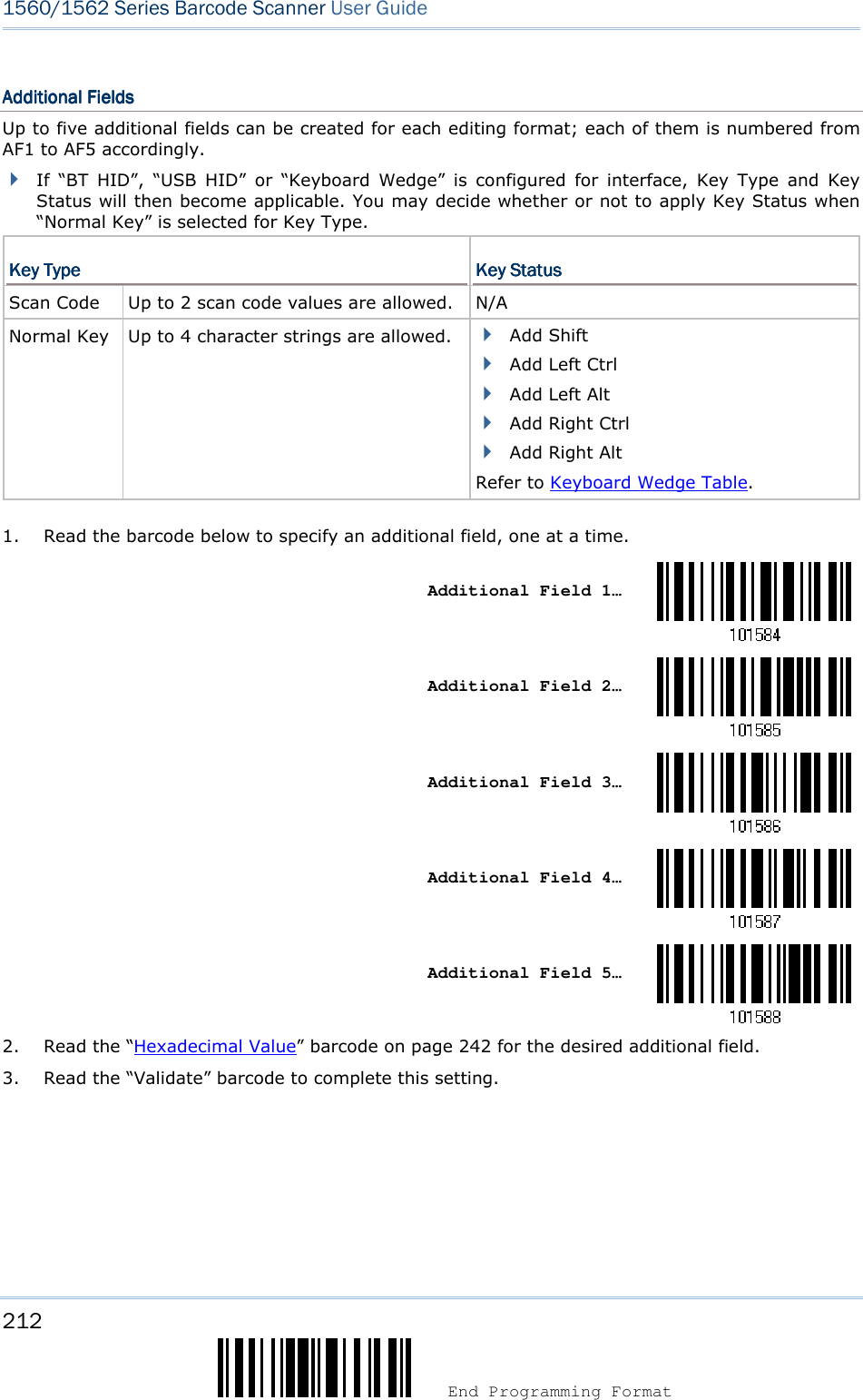
![213 Update Chapter 6 ! ! ! ! [[[[]]]] Heading 1 Heading 1 Heading 1 Heading 1 6.4.5 PAUSE FIELD SE6.4.5 PAUSE FIELD SE6.4.5 PAUSE FIELD SE6.4.5 PAUSE FIELD SETTINGTTINGTTINGTTING Pause Field TimePause Field TimePause Field TimePause Field Time You can limit the pause time interval (1~16). By default, it is set to 1 second. Pause Field Time 1~16 sec. (*1) 1. Read the barcode above to specify the time interval for the Pause Field. (It is set to 1 by default.) 2. Read the “Decimal Value” barcode on page 241. For example, read “1” and “0” for setting the Pause Field Time to 10 seconds. 3. Read the “Validate” barcode on the same page to complete this setting.](https://usermanual.wiki/CipherLab/3656CRADLE/User-Guide-3879656-Page-231.png)
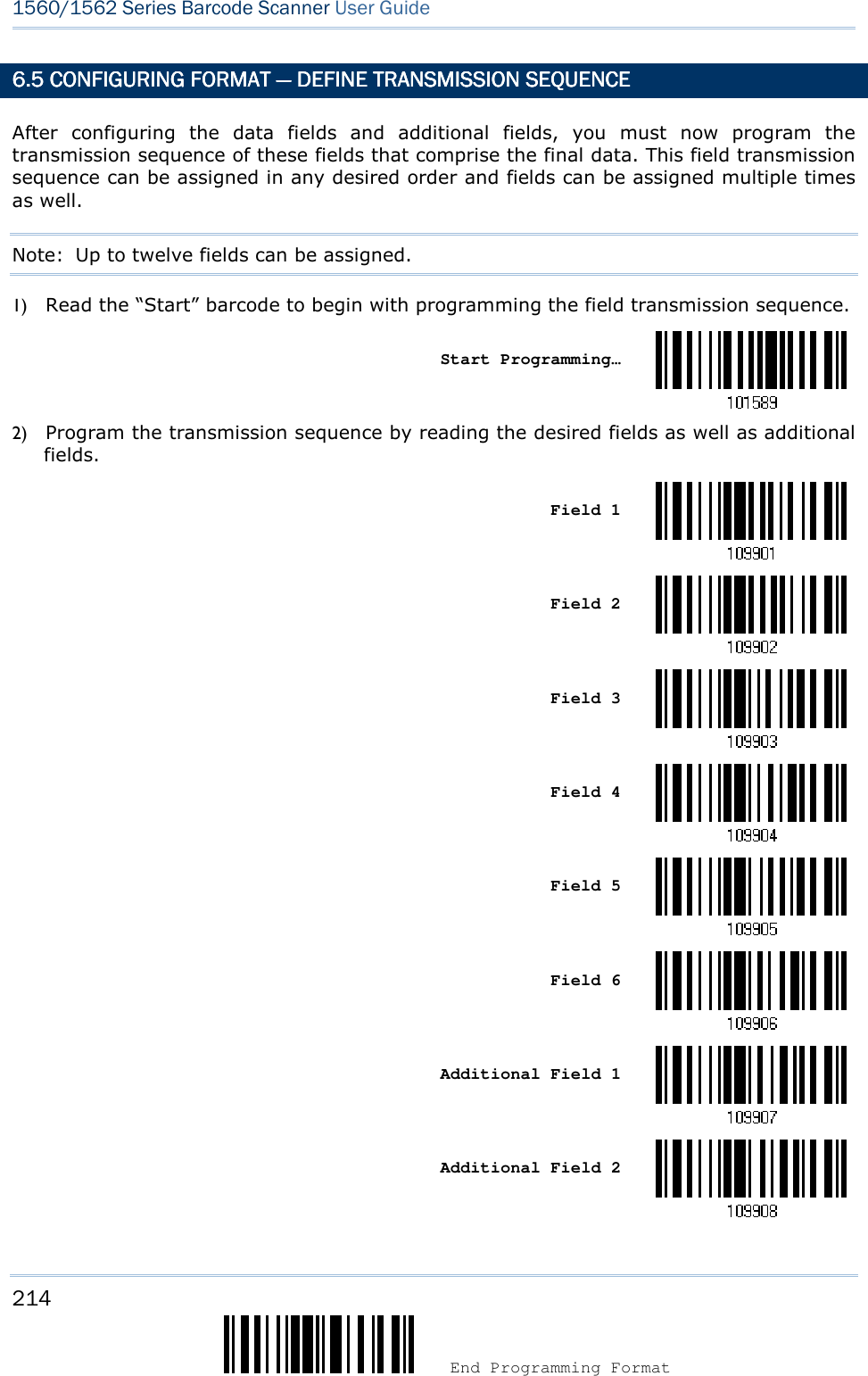
![215 Update Chapter 6 ! ! ! ! [[[[] ] ] ] Heading 1 Heading 1 Heading 1 Heading 1 Additional Field 3 Additional Field 4 Additional Field 5 Pause Field Null Character Field 3) Read the “End” barcode to complete this setting. End Programming…](https://usermanual.wiki/CipherLab/3656CRADLE/User-Guide-3879656-Page-233.png)
![217 Update Chapter 6 ! ! ! ! [[[[] ] ] ] Heading 1 Heading 1 Heading 1 Heading 1 6666....6666.2 EXAMPLE II.2 EXAMPLE II.2 EXAMPLE II.2 EXAMPLE II Extract the date code, item number, and quantity information from barcodes.Extract the date code, item number, and quantity information from barcodes.Extract the date code, item number, and quantity information from barcodes.Extract the date code, item number, and quantity information from barcodes. Data in a barcode is encoded like this: From the 1st character to the 6th character is the date code. From the 7th character to the dash ‘-’ character is the item number. After the dash ‘-’ character is the quantity information. Data will be transmitted like this: The item number goes first, then a TAB character, followed by the date code, then another TAB character, and finally the quantity information. The editing format should be configured as follows: 1. Read the “Enter Setup” barcode to enter the Configuration Mode. 2. Read the “Configure Format 2” barcode. 3. Read the “Three Fields” barcode. 4. Read the “Divide Field 1 by Length” barcode, and set length to 6. Field 1 data starts from the 1st character to the 6th character. 5. Read the “Select Field Separator to Divide Field 2” barcode, and use a dash ‘-’ character. Field 2 data starts from the 7th character until the dash ‘-’ character is met. 6. Read the “Additional Field 1” barcode, and use a tab character for the field. 7. Read the “Start (Programming)” barcode to program the transmission sequence. 8. Read the “Field 2”, “Additional Field 1”, “Field 1”, “Additional Field 1”, “Field 3” barcodes. 9. Read the “End” barcode to complete the transmission sequence (F2 A1 F1 A1 F3) setting. 10. Read the “End Programming Format” barcode to complete the setting of Editing Format 1. 11. Read the “Enable Format 2” barcode to apply Editing Format 2 to all code types. 12. Read the “Update” barcode to exit the Configuration Mode.](https://usermanual.wiki/CipherLab/3656CRADLE/User-Guide-3879656-Page-235.png)
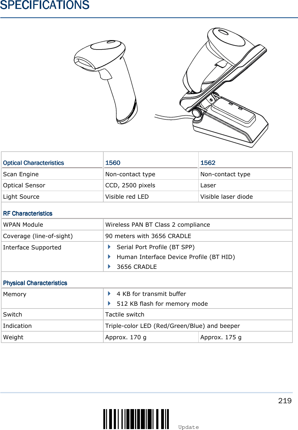
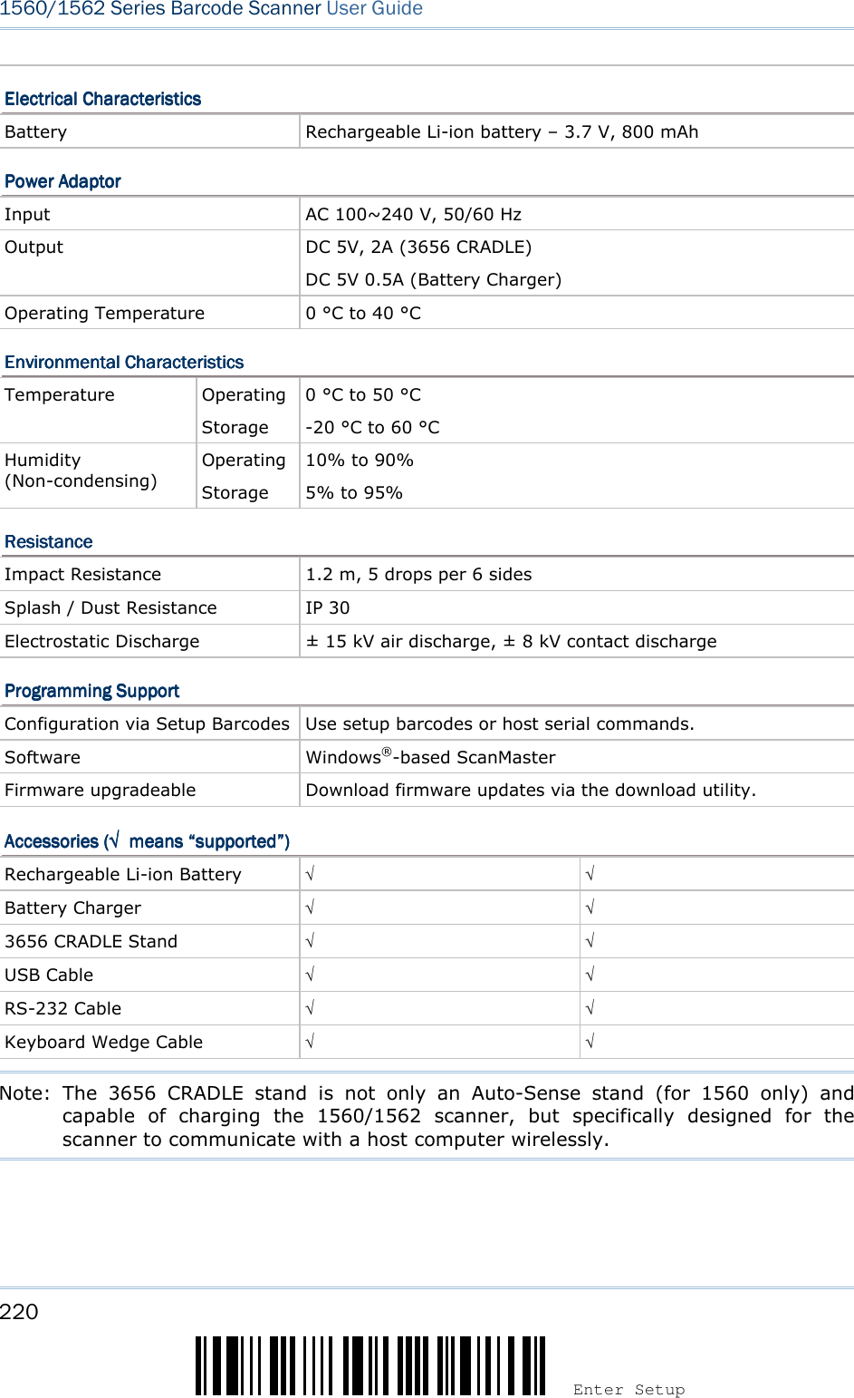
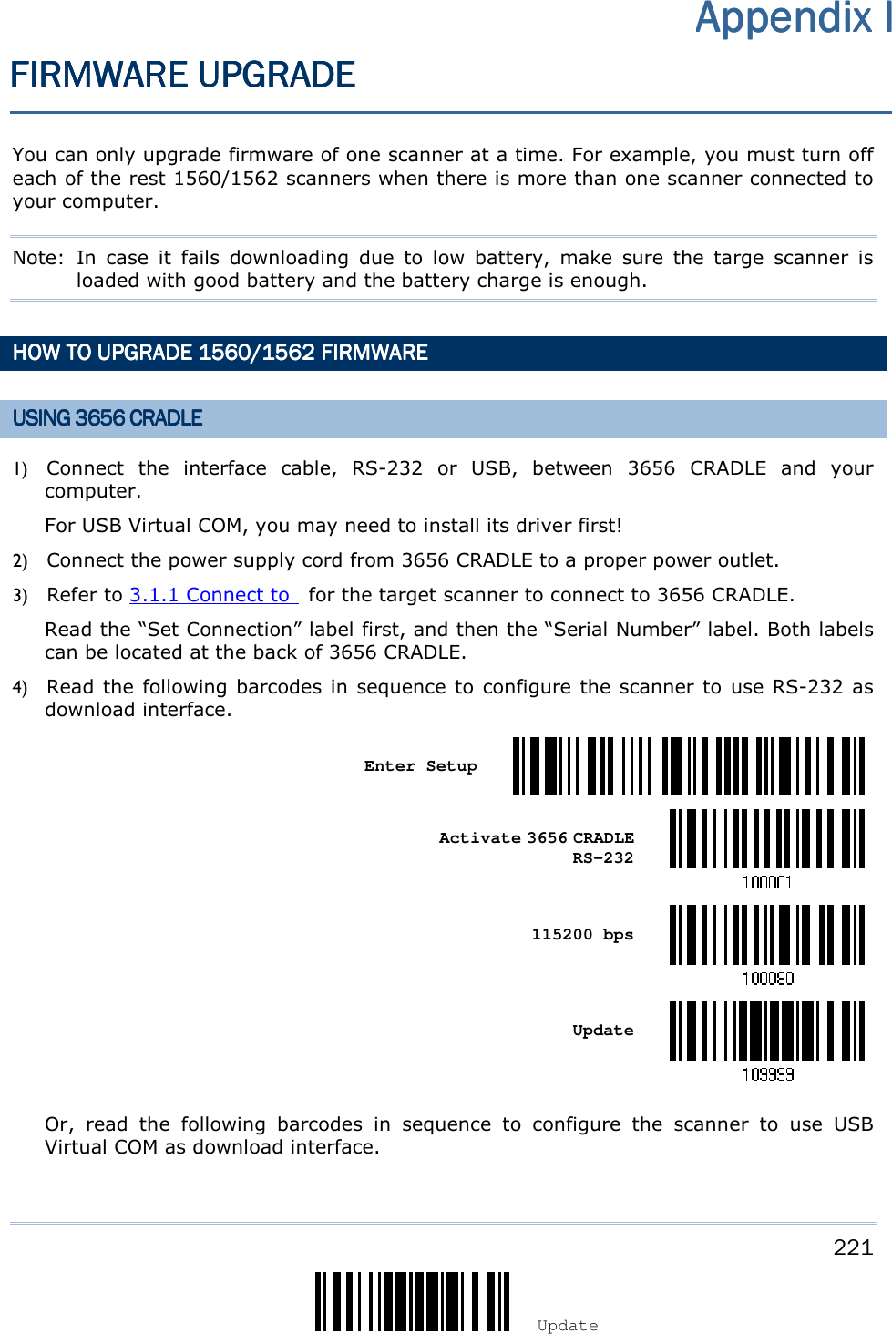
![222 Enter Setup 1560/1562 Series Barcode Scanner User Guide Enter Setup Activate 3656 CRADLE USB Virtual COM Update 5) Read the following barcodes in sequence for the scanner to enter the download mode. The scanner will respond with beeps to indicate it is ready for downloading. Enter Setup Download 6) Run the download utility “ProgLoad.exe” on your computer. Kernel ProgramKernel ProgramKernel ProgramKernel Program User ProgramUser ProgramUser ProgramUser Program K1560_V*.shx STD1560_V*.shx For the communication settings, select “RS-232” and the correct COM port for RS-232 or USB Virtual COM interface. For RS-232, select 115200 bps for baud rate; for USB Virtual COM, ignore the baud rate setting. For the file option, click [Browse] to select the target file for firmware update. Click [OK]. 7) After upgrading kernel, you will need to manually restart the scanner. After upgrading the user program, the scanner will automatically restart itself once the download is completed successfully.](https://usermanual.wiki/CipherLab/3656CRADLE/User-Guide-3879656-Page-240.png)
![223 Update Appendix I ! ! ! ! [[[[] ] ] ] Heading 1 Heading 1 Heading 1 Heading 1 Note: The output interface remains unchanged as specified in step 3 (= RS-232 or USB Virtual COM). For RS-232, the baud rate setting is still 115200 bps!](https://usermanual.wiki/CipherLab/3656CRADLE/User-Guide-3879656-Page-241.png)
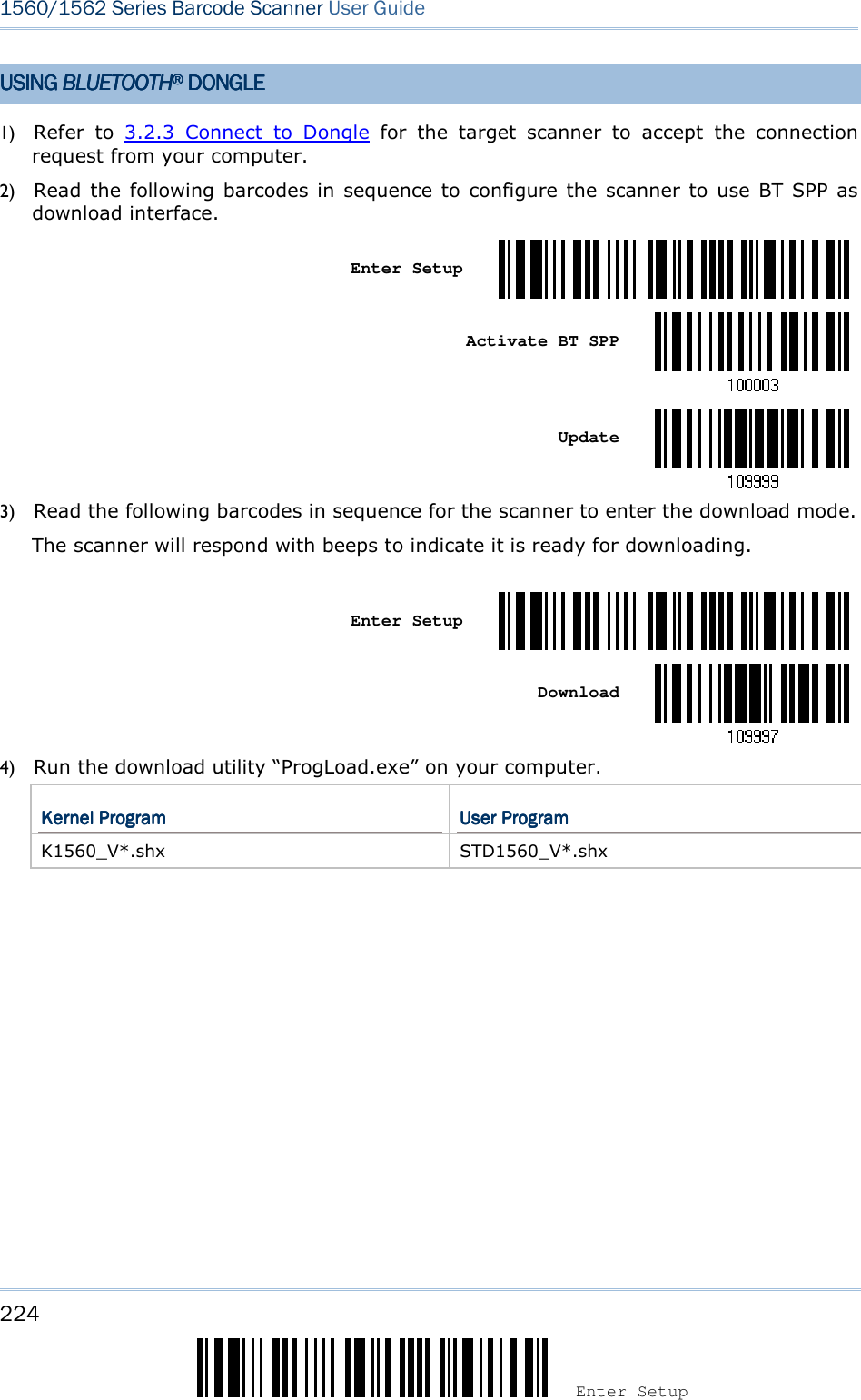
![225 Update Appendix I ! ! ! ! [[[[] ] ] ] Heading 1Heading 1Heading 1Heading 1 For the communication settings, select “RS-232” and the correct COM port for BT SPP interface. Ignore the baud rate setting. For the file option, click [Browse] to select the target file for firmware update. Click [OK]. 5) After upgrading kernel, you will need to manually restart the scanner. After upgrading the user program, the scanner will automatically restart itself once the download is completed successfully. Note: The output interface remains unchanged as specified in step 2 (= BT SPP).](https://usermanual.wiki/CipherLab/3656CRADLE/User-Guide-3879656-Page-243.png)
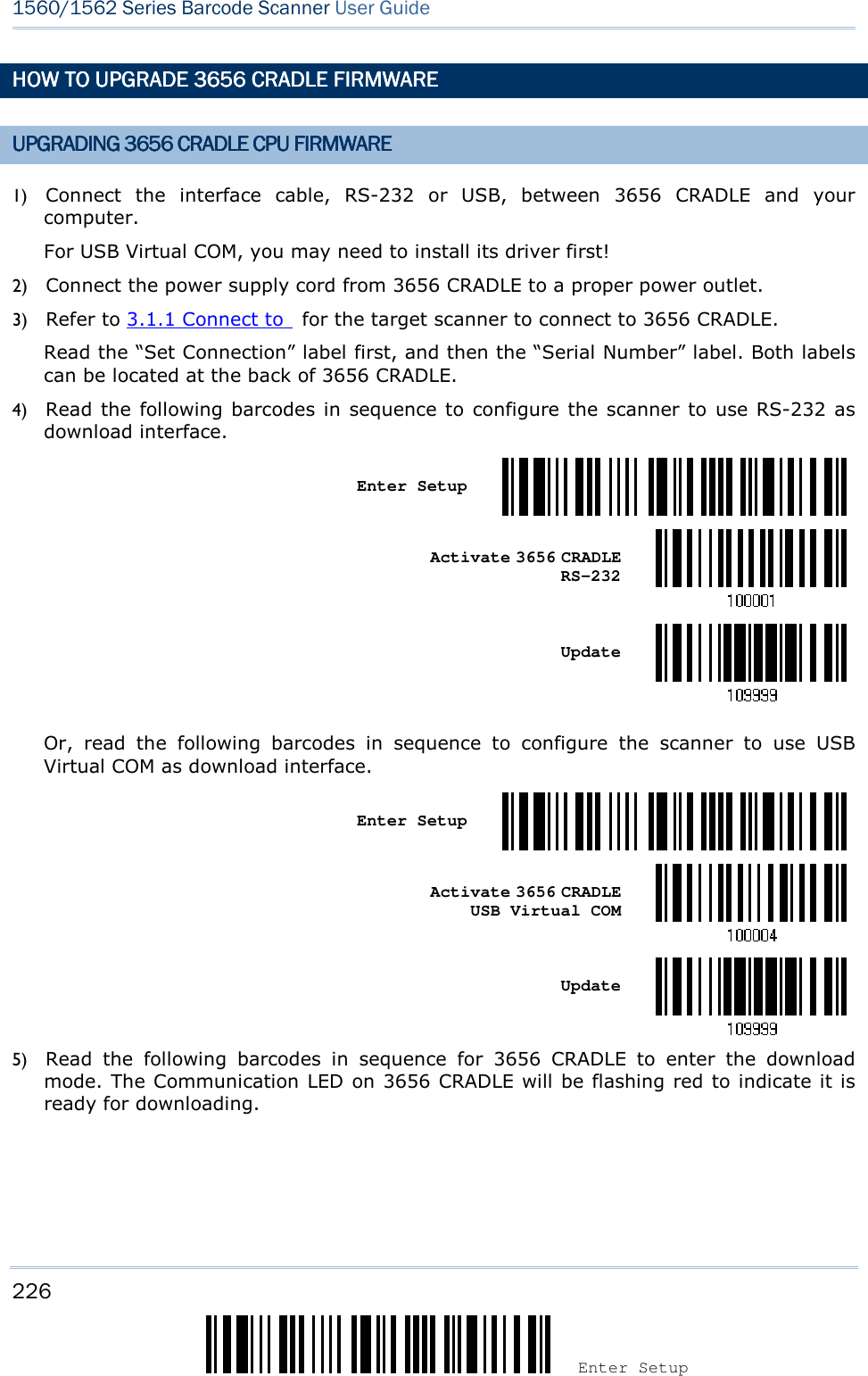
![227 Update Appendix I ! ! ! ! [[[[] ] ] ] Heading 1 Heading 1 Heading 1 Heading 1 Enter Setup Download 3656 CRADLE CPU Firmware 6) Run the download utility “ProgLoad.exe” on your computer. Kernel ProgramKernel ProgramKernel ProgramKernel Program User ProgramUser ProgramUser ProgramUser Program K3656 CRADLE _V*.shx STD3656 CRADLE _V*.shx For the communication settings, select “RS-232” and the correct COM port for RS-232 or USB Virtual COM interface. For RS-232, select 115200 bps for baud rate; for USB Virtual COM, ignore the baud rate setting. For the file option, click [Browse] to select the target file for firmware update. Click [OK]. 7) The 3656 CRADLE will automatically restart itself when upgrading firmware is completed successfully. 8) Read the “Update” barcode for the scanner to resume its operation (exit the configuration mode). Update](https://usermanual.wiki/CipherLab/3656CRADLE/User-Guide-3879656-Page-245.png)
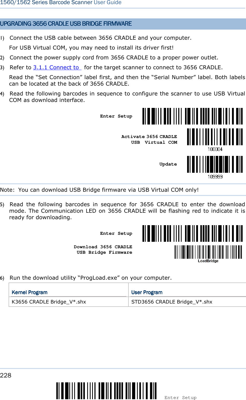
![229 Update Appendix I ! ! ! ! [[[[] ] ] ] Heading 1 Heading 1 Heading 1 Heading 1 For the communication settings, select “RS-232” and the correct COM port for USB Virtual COM interface. Ignore the baud rate setting. For the file option, click [Browse] to select the target file for firmware update. Click [OK]. 7) The 3656 CRADLE will automatically restart itself when upgrading firmware is completed successfully. 8) Read the “Update” barcode for the scanner to resume its operation (exit the configuration mode). Update](https://usermanual.wiki/CipherLab/3656CRADLE/User-Guide-3879656-Page-247.png)

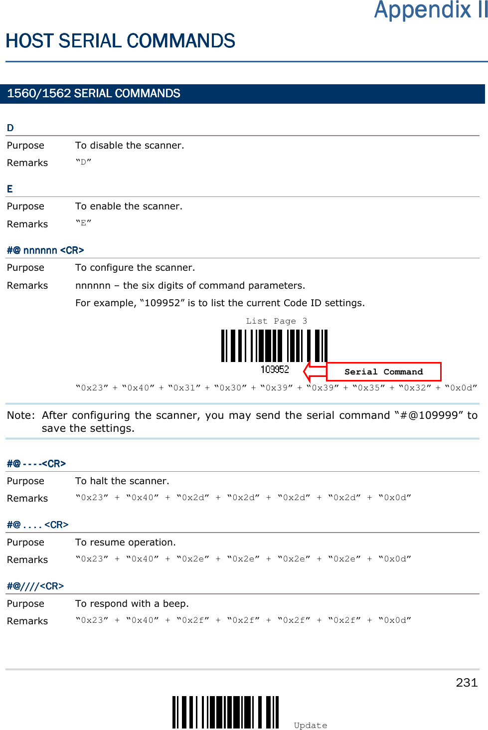
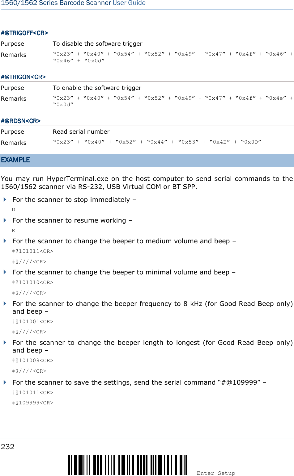
![233 Update Appendix II ! ! ! ! [[[[] ] ] ] Heading 1 Heading 1 Heading 1 Heading 1 For the scanner to read the serial number and beep – #@RDSN<CR> #@////<CR> Note: (1) For RS-232 or USB Virtual COM, you can only configure the first scanner that connects to 3656 CRADLE. To identify the scanner, you may send the serial command to have it respond with a beep. (2) For BT SPP, you can configure up to seven scanners at the same time. 3656365636563656 CRADLECRADLECRADLECRADLE SETUP SETUP SETUP SETUP BARCODEBARCODEBARCODEBARCODES & S & S & S & SERIAL COMMANDSSERIAL COMMANDSSERIAL COMMANDSSERIAL COMMANDS Normally, you can configure the 3656 CRADLE stand by having a connected scanner read 3656 CRADLE -related setup barcodes. 1) Connect the interface cable, RS-232, Keyboard Wedge or USB, between 3656 CRADLE and your computer. For USB Virtual COM, you may need to install its driver first! 2) Connect the power supply cord from 3656 CRADLE to a proper power outlet. 3) Refer to 3.1.1 Connect to for the target scanner to connect to 3656 CRADLE. Read the “Set Connection” label first, and then the “Serial Number” label. Both labels can be located at the back of 3656 CRADLE. 4) Read the following barcodes in sequence to configure 3656 CRADLE. Enter Setup Update For 3656 CRADLE -related setup barcodes, refer to the Serial Command table below. Note that for the “Version” and “GetID” barcodes, you must run HyperTerminal.exe or any text editor to receive the information. If the output interface is RS-232 or USB Virtual COM, run HyperTerminal.exe on your computer to receive the information. If the output interface is Keyboard Wedge or USB HID, run any text editor to receive the information. (3656-related setup barcodes)](https://usermanual.wiki/CipherLab/3656CRADLE/User-Guide-3879656-Page-251.png)
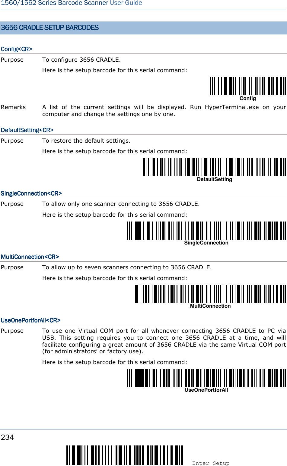
![235 Update Appendix II ! ! ! ! [[[[] ] ] ] Heading 1 Heading 1 Heading 1 Heading 1 UseVariablePortUseVariablePortUseVariablePortUseVariablePort<CR><CR><CR><CR> Purpose To use variable Virtual COM port when connecting more than one 3656 CRADLE to PC via USB. Here is the setup barcode for this serial command: UseVariablePort VersionVersionVersionVersion<CR><CR><CR><CR> Purpose To get the firmware versions (CPU+USB Bridge). Here is the setup barcode for this serial command: Version GetIDGetIDGetIDGetID<CR><CR><CR><CR> Purpose To get MAC ID. Here is the setup barcode for this serial command: GetID DownloadDownloadDownloadDownload<CR><CR><CR><CR> Purpose To download CPU firmware to 3656 CRADLE via RS-232 or USB. Here is the setup barcode for this serial command: Download LoadBridgeLoadBridgeLoadBridgeLoadBridge<CR><CR><CR><CR> Purpose To download USB Bridge firmware to 3656 CRADLE via USB only. Here is the setup barcode for this serial command: LoadBridge](https://usermanual.wiki/CipherLab/3656CRADLE/User-Guide-3879656-Page-253.png)
![236 Enter Setup 1560/1562 Series Barcode Scanner User Guide EXAMPLEEXAMPLEEXAMPLEEXAMPLE Without using the scanner to read the above setup barcodes for configuring the 3656 CRADLE stand, you may run HyperTerminal.exe on the host computer to send serial commands to 3656 CRADLE via RS-232 or USB. 1) Connect the interface cable, RS-232 or USB, between 3656 CRADLE and your computer. For USB Virtual COM, you may need to install its driver first! 2) Connect the power supply cord from 3656 CRADLE to a proper power outlet. The Communication LED will indicate when 3656 CRADLE can accept serial commands after initializing. Refer to the table below. If the output interface is USB Virtual COM or RS-232, run HyperTerminal.exe on your computer. While the Communication LED on 3656 CRADLE is purple (red with flashing blue), type the serial command within three seconds. If the output interface is USB HID, press the “Num Lock” or “Caps Lock” key on your keyboard 5 times within 3 seconds while the Communication LED on 3656 CRADLE is flashing red and blue. This will change the interface from USB HID to USB Virtual COM and the Communication LED will become purple (red with flashing blue). Then, run HyperTerminal.exe on your computer. While the Communication LED on 3656 CRADLE is purple (red with flashing blue), type the serial command within three seconds. After configuring via serial commands, the interface will be reset to USB HID after re-connecting the power supply cord. Communication LEDCommunication LEDCommunication LEDCommunication LED MMMMeaningeaningeaningeaning --- Blue, solid Initialize Red, solid Blue, flashing Serial command mode with USB Virtual COM or RS-232: wait 3 seconds for starting a serial command Red, flashing Blue, flashing Serial command mode with USB HID changed to USB Virtual COM first: wait 3 seconds for pressing [Num Lock] or [Caps Lock] 5 times via keyboard](https://usermanual.wiki/CipherLab/3656CRADLE/User-Guide-3879656-Page-254.png)
![237 Update 0 1 2 3 4 5 6 7 8 0 F2 SP 0 @ P ` p 1 INS F3 ! 1 A Q a q 2 DLT F4 " 2 B R b r 3 Home F5 # 3 C S c s 4 End F6 $ 4 D T d t 5 Up F7 % 5 E U e u 6 Down F8 & 6 F V f v 7 Left F9 ' 7 G W g w 8 BS F10 ( 8 H X h x 9 HT F11 ) 9 I Y i y A LF F12 * : J Z j z B Right ESC + ; K [ k { C PgUp Exec , < L \ l | D CR CR* - = M ] m } E PgDn . > N ^ n ~ F F1 / ? O _ o Dly ENTER* Note: (1) ~: Digits of numeric keypad. (2) CR*/ENTER*: ENTER key on the numeric keypad. Appendix Appendix Appendix Appendix IIIIIIIIIIII KEYBOARD WEDGE TABLEKEYBOARD WEDGE TABLEKEYBOARD WEDGE TABLEKEYBOARD WEDGE TABLE](https://usermanual.wiki/CipherLab/3656CRADLE/User-Guide-3879656-Page-255.png)
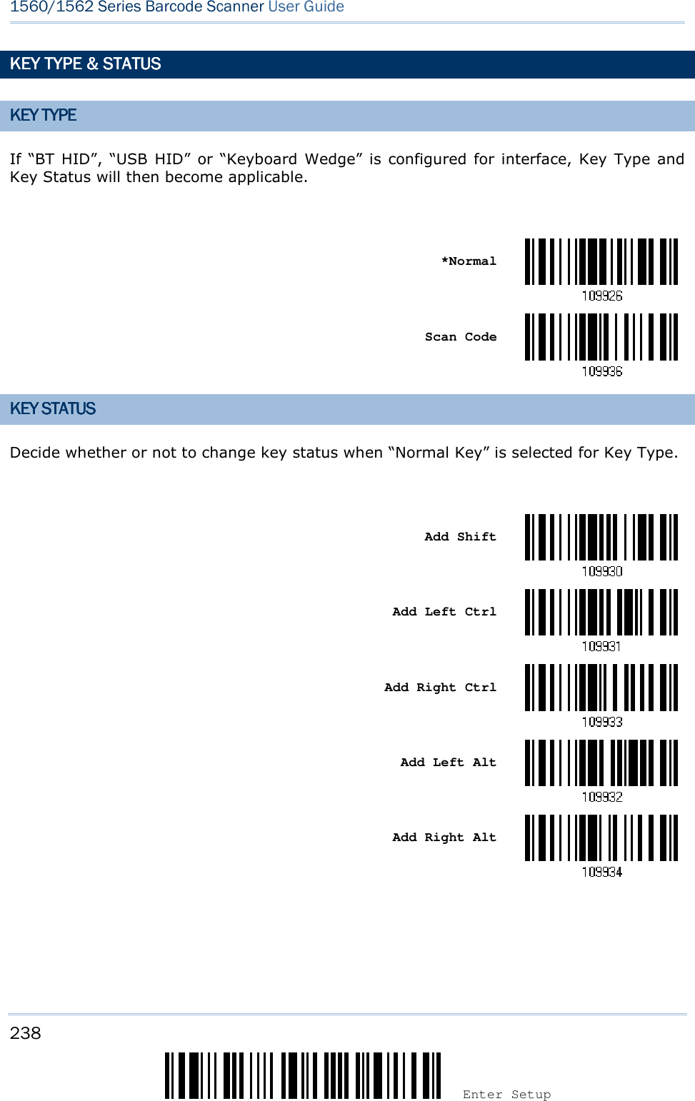
![239 Update Appendix III ! ! ! ! [[[[] ] ] ] Heading 1 Heading 1 Heading 1 Heading 1 EXAMPLEEXAMPLEEXAMPLEEXAMPLE KEY TYPE = NORMALKEY TYPE = NORMALKEY TYPE = NORMALKEY TYPE = NORMAL For example, if you want to program the character “!” as the prefix code: 1. Read the “Configure Prefix” barcode. 2. Read the “Hexadecimal Value” barcode on page 242 for “2” and “1”. 3. Read the “Validate” barcode to complete this setting. KEY TYPE = SCAN CODEKEY TYPE = SCAN CODEKEY TYPE = SCAN CODEKEY TYPE = SCAN CODE For example, if you want to program the character “a” (= “1C” on the scan code table) as the prefix code: 1. Read the “Configure Prefix” barcode. 2. Read the “Scan Code” barcode. 3. Read the “Hexadecimal Value” barcode on page 242 for “1” and “C”. 4. Read the “Validate” barcode to complete this setting. KEY TYPE = NORMAL + KEY TYPE = NORMAL + KEY TYPE = NORMAL + KEY TYPE = NORMAL + KEY STATUS = SHIFTKEY STATUS = SHIFTKEY STATUS = SHIFTKEY STATUS = SHIFT For example, if you want to program the character “!” (= “Shift” + “1” on keyboard) as the prefix code: 1. Read the “Configure Prefix” barcode. 2. Read the “Add Shift” barcode. 3. Read the “Hexadecimal Value” barcode on page 242 for “3” and “1”. 4. Read the “Validate” barcode to complete this setting. KEY TYPE = NORMAL + KEY TYPE = NORMAL + KEY TYPE = NORMAL + KEY TYPE = NORMAL + KEY STATUSKEY STATUSKEY STATUSKEY STATUS = CTRL= CTRL= CTRL= CTRL For example, if you want to program “Ctrl+A” and “Ctrl+$” as the prefix code: 1. Read the “Configure Prefix” barcode. 2. Read the “Add Left Ctrl” barcode. 3. Read the “Hexadecimal Value” barcode on page 242 for “4”, “1” (= “A”). 4. Read the “Add Left Ctrl” barcode. 5. Read the “Hexadecimal Value” barcode on page 242 for “2”, “4” (= “$”). 6. Read the “Validate” barcode to complete this setting.](https://usermanual.wiki/CipherLab/3656CRADLE/User-Guide-3879656-Page-257.png)
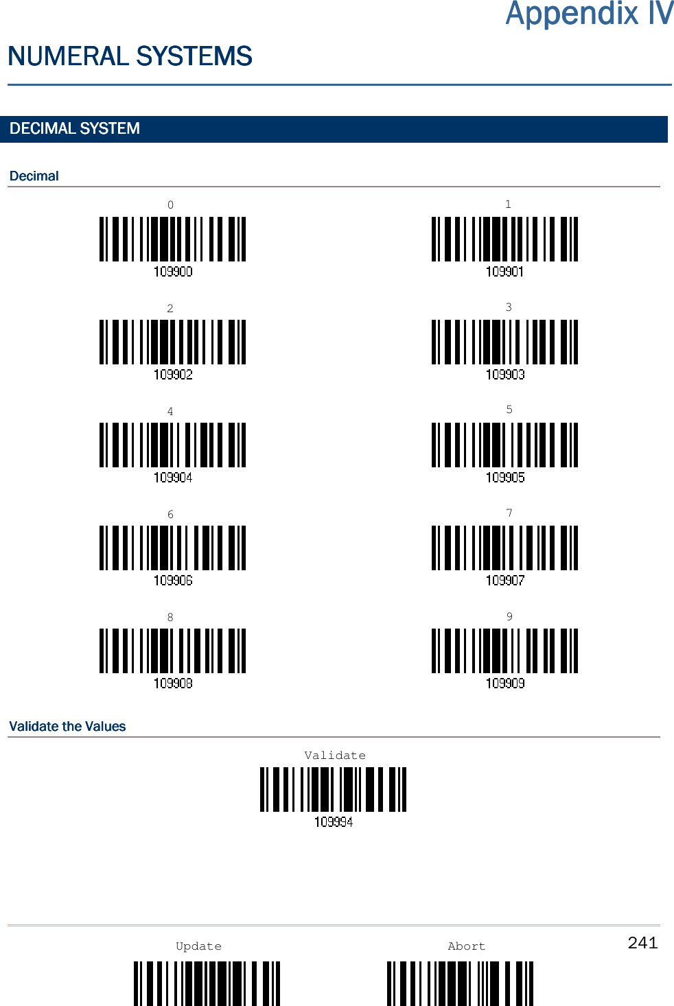
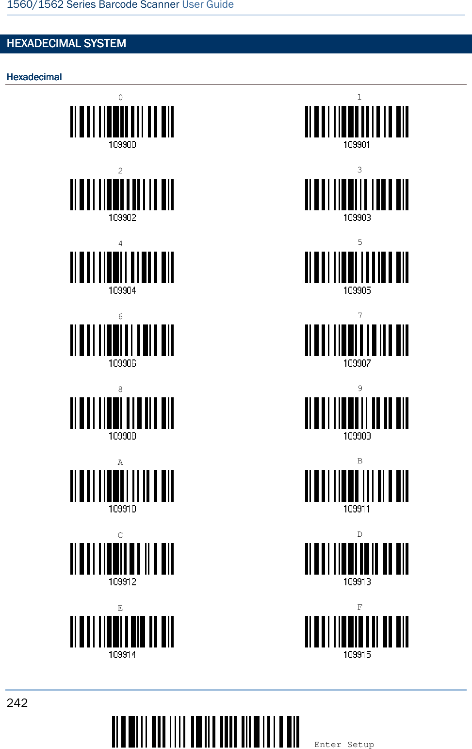
![243 Appendix IV ! ! ! ! [[[[] ] ] ] Heading 1 Heading 1 Heading 1 Heading 1 Update Abort Validate the ValuesValidate the ValuesValidate the ValuesValidate the Values ASCII TABLEASCII TABLEASCII TABLEASCII TABLE 0 1 2 3 4 5 6 7 0 DLE SP 0 @ P ` p 1 SOH DC1 ! 1 A Q a q 2 STX DC2 " 2 B R b r 3 ETX DC3 # 3 C S c s 4 EOT DC4 $ 4 D T d t 5 ENQ NAK % 5 E U e u 6 ACK SYN & 6 F V f v 7 BEL ETB ' 7 G W g w 8 BS CAN ( 8 H X h x 9 HT EM ) 9 I Y i y A LF SUB * : J Z j z B VT ESC + ; K [ k { C FF FS , < L \ l | D CR GS - = M ] m } E SO RS . > N ^ n ~ F SI US / ? O _ o DEL Validate](https://usermanual.wiki/CipherLab/3656CRADLE/User-Guide-3879656-Page-261.png)
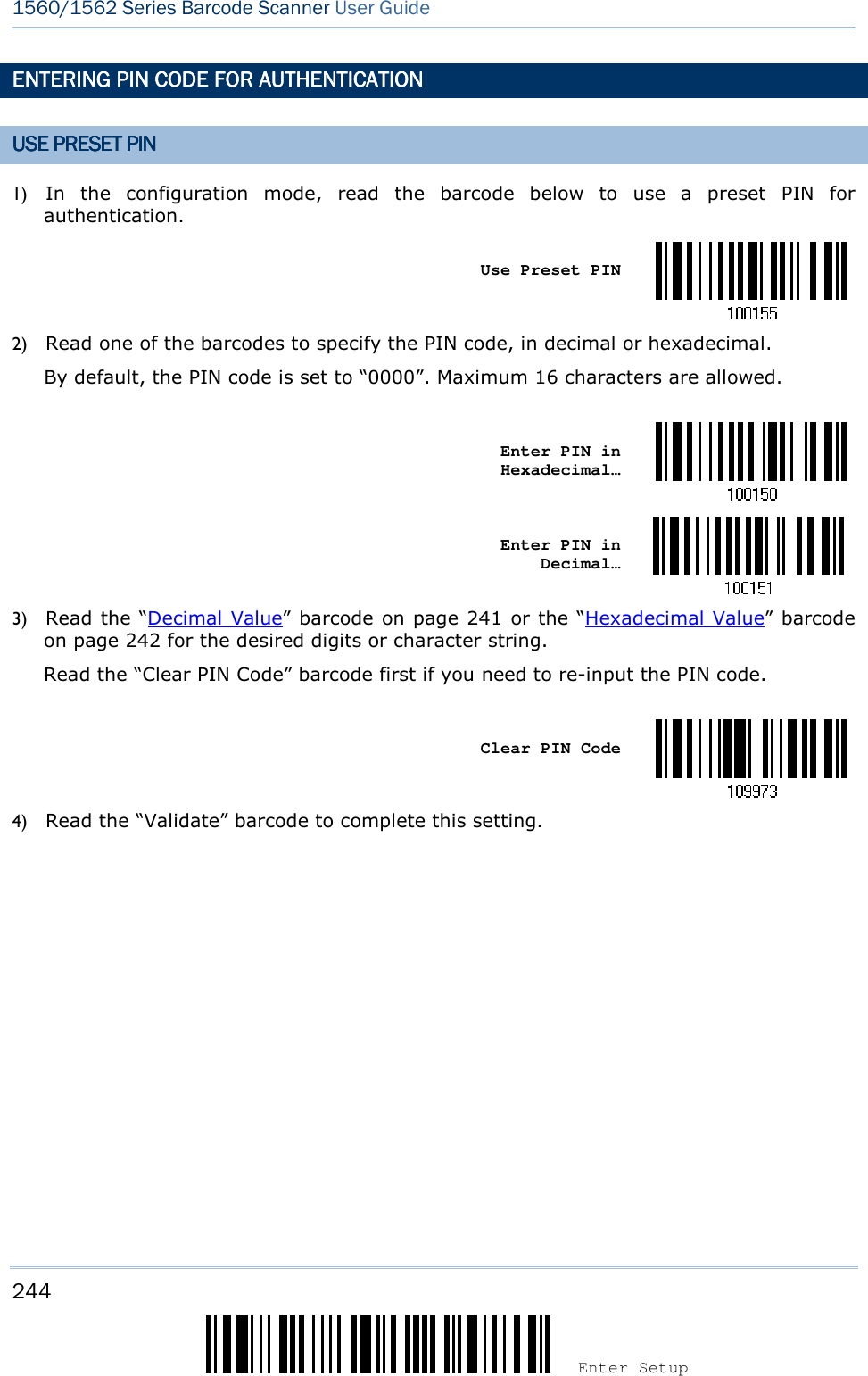
![245 Appendix IV ! ! ! ! [[[[] ] ] ] Heading 1 Heading 1 Heading 1 Heading 1 Update Abort DISABLEDISABLEDISABLEDISABLE AUTHENTICATIONAUTHENTICATIONAUTHENTICATIONAUTHENTICATION OR UOR UOR UOR USE RANDOM PINSE RANDOM PINSE RANDOM PINSE RANDOM PIN In the configuration mode, read the barcode below to disable authentication (= No PIN) or use a random PIN for authentication. *No PIN or use random PIN Note: When using BT HID, some device driver may not support pre-defined PIN code for authentication. In this case, make sure you have the scanner set to “No PIN or use random PIN” before pairing. While pairing, the host PIN code will be displayed on the computer screen. Use Random PINUse Random PINUse Random PINUse Random PIN When the target device is set to use a random PIN for authentication, wait until the random PIN is displayed on the target device while pairing, and then input the matching PIN code on the scanner. Note: Follow the steps below to enter the matching PIN on the scanner. There is no need to enter the configuration mode! 1. Read one of the barcodes to specify the PIN code, in decimal or hexadecimal. Enter PIN in Hexadecimal… Enter PIN in Decimal… 2. Read the “Decimal Value” barcode on page 241 or the “Hexadecimal Value” barcode on page 242 for the desired digits or character string. Read the “Clear PIN Code” barcode first if you need to re-input the PIN. Clear PIN Code 3. Read the “Validate” barcode to complete this setting. Reject Random PIN RequestReject Random PIN RequestReject Random PIN RequestReject Random PIN Request When the random PIN is displayed on the target device while pairing, you can reject the PIN request by having the scanner read the “Validate” barcode.](https://usermanual.wiki/CipherLab/3656CRADLE/User-Guide-3879656-Page-263.png)