CipherLab 3656CRADLE Cradle User Manual
CipherLab Co., Ltd. Cradle Users Manual
Users Manual
1560/1562 Barcode Scanner
3656 CRADLE
Setup barcodes included.
Version 1.21

Copyright © 2009~2017 CIPHERLAB CO., LTD.
All rights reserved
The software contains proprietary information of CIPHERLAB CO., LTD.; it is provided
under a license agreement containing restrictions on use and disclosure and is also
protected by copyright law. Reverse engineering of the software is prohibited.
Due to continued product development this information may change without notice. The
information and intellectual property contained herein is confidential between CIPHERLAB
and the client and remains the exclusive property of CIPHERLAB CO., LTD. If you find
any problems in the documentation, please report them to us in writing. CIPHERLAB
does not warrant that this document is error-free.
No part of this publication may be reproduced, stored in a retrieval system, or
transmitted in any form or by any means, electronic, mechanical, photocopying,
recording or otherwise without the prior written permission of CIPHERLAB CO., LTD.
For product consultancy and technical support, please contact your local sales
representative. Also, you may visit our web site for more information.
The CipherLab logo is a registered trademark of CIPHERLAB CO., LTD.
All brand, product and service, and trademark names are the property of their registered
owners.
The editorial use of these names is for identification as well as to the benefit of the
owners, with no intention of infringement.
CIPHERLAB CO., LTD.
Website: http://www.cipherlab.com

F
FF
FOR USA
OR USAOR USA
OR USA
This equipment has been tested and found to comply with the limits for a Class B digital
device, pursuant to Part 15 of the FCC Rules. These limits are designed to provide
reasonable protection against harmful interference in a residential installation. This
equipment generates, uses and can radiate radio frequency energy and, if not installed
and used in accordance with the instructions, may cause harmful interference to radio
communications. However, there is no guarantee that interference will not occur in a
particular installation. If this equipment does cause harmful interference to radio or
television reception, which can be determined by turning the equipment off and on, the
user is encouraged to try to correct the interference by one or more of the following
measures:
Reorient or relocate the receiving antenna.
Increase the separation between the equipment and receiver.
Connect the equipment into an outlet on a circuit different from that to which the
receiver is connected.
Consult the dealer or an experienced radio/TV technician for help.
This device complies with Part 15 of the FCC Rules. Operation is subject to the following
two conditions: (1) This device may not cause harmful interference, and (2) this device
must accept any interference received, including interference that may cause undesired
operation.
FCC Caution: Any changes or modifications not expressly approved by the party
responsible for compliance could void the user's authority to operate this equipment.
This transmitter must not be co-located or operating in conjunction with any other
antenna or transmitter.
Radiation Exposure Statement:
This equipment complies with FCC radiation exposure limits set forth for an uncontrolled
environment. This equipment should be installed and operated with minimum distance
20cm between the radiator & your body.
FOR CANADA
FOR CANADAFOR CANADA
FOR CANADA
This digital apparatus does not exceed the Class B limits for radio noise emissions from
digital apparatus as set out in the interference-causing equipment standard entitled
"Digital Apparatus," ICES-003 of Industry Canada. This device complies with Part 15 of
the FCC Rules. Operation is subject to the following two conditions: (1) This device may
not cause harmful interference, and (2) this device must accept any interference received,
including interference that may cause undesired operation.
IMPORTANT NOTICES
IMPORTANT NOTICESIMPORTANT NOTICES
IMPORTANT NOTICES

Cet appareil numerique respecte les limites de bruits radioelectriques applicables aux
appareils numeriques de Classe B prescrites dans la norme sur le material brouilleur:
"Appareils Numeriques," NMB-003 edictee par l'Industrie.
FOR
FOR FOR
FOR EUROPE
EUROPEEUROPE
EUROPE
This device complies with the essential requirements of the R&TTE Directive 1999/5/EC.
The following test methods have been applied in order to prove presumption of
conformity with the essential requirements of the R&TTE Directive 1999/5/EC:
- EN 60950-1: 2006+A11:2009+A1:2010+A12:2011+A2:2013
Safety of Information Technology Equipment
- EN 301 489-1 V2.1.1: 2016
Electromagnetic compatibility and Radio Spectrum Matters (ERM); ElectroMagnetic
Compatibility (EMC) standard for radio equipment and services; Part 1: Common
technical requirements
- EN 301 489-3 V2.1.0: 2016
Electromagnetic compatibility and Radio Spectrum Matters (ERM); ElectroMagnetic
Compatibility (EMC) standard for radio equipment and services; Part 3: Specific
conditions for Short-Range Devices (SRD) operating on frequencies between 9 kHz and
40 GHz
- EN 301 489-17 V3.1.1: 2016
ElectroMagnetic Compatibility (EMC) standard for radio equipment and services; Part 17:
Specific conditions for Broadband Data Transmission Systems; Harmonised Standard
covering the essential requirements of article 3.1(b) of Directive 2014/53/EU
- EN 300 328 V2.1.1: 2016
Wideband transmission systems;Data transmission equipment operating in the 2,4 GHz
ISM band and using wide band modulation techniques; Harmonised Standard covering
the essential requirements of article 3.2 of Directive 2014/53/EU
FOR
FORFOR
FOR
HAND
HANDHAND
HAND-
--
-HELD PRODUCT WITH RF
HELD PRODUCT WITH RFHELD PRODUCT WITH RF
HELD PRODUCT WITH RF
FUNCTIONS
FUNCTIONSFUNCTIONS
FUNCTIONS
The 1560/1562 unit (FCC ID: Q3N-1560) complies with FCC radiation exposure limits set
forth for uncontrolled environment and meets the FCC radio frequency (RF) Exposure
Guidelines in Supplement C to OET65. The unit has very low level of RF energy that it is
deemed to comply without testing of specific absorption ratio (SAR).
The 3656 CRADLE CRADLE unit (FCC ID: Q3N-3656CRADLE) complies with FCC radiation
exposure limits set forth for an uncontrolled environment. This equipment should be
installed and operated with minimum distance 20 cm between the radiator & your body.
It only operated in hand-held used. If you only transfer data to the host wirelessly,
please keep the minimum distance 20 cm between machine & your body.
FOR PRODUCT WITH LAS
FOR PRODUCT WITH LASFOR PRODUCT WITH LAS
FOR PRODUCT WITH LASER
ERER
ER
CAUTION
This laser component emits FDA / IEC Class 2 laser light at the exit port. Do not
stare into beam.
SAFETY PRECAUTIONS
SAFETY PRECAUTIONSSAFETY PRECAUTIONS
SAFETY PRECAUTIONS
DO NOT expose the scanner to any flammable sources.
Under no circumstances, internal components are self-serviceable.
For AC power adaptor, a socket outlet shall be installed near the equipment and shall
be easily accessible. Make sure there is stable power supply for the scanner or its
peripherals to operate properly.
CARE & MAINTENANCE
CARE & MAINTENANCECARE & MAINTENANCE
CARE & MAINTENANCE
Use a clean cloth to wipe dust off the scanning window and the body of the scanner.
DO NOT use/mix any bleach or cleaner.
If finding the scanner malfunctioning, write down the specific scenario and consult the
local sales representative.
Version
VersionVersion
Version
Date
DateDate
Date
Notes
NotesNotes
Notes
RELEASE NOTES
RELEASE NOTESRELEASE NOTES
RELEASE NOTES
1.21 Jul. 13, 2017
Modified: 2.3.1 Activate BT SPP Master Mode – settings as
a
single 1D barcode (SeTcOn) for connecting to a target device added
Modified: 3.1.1 Connect to 3656 CRADLE – settings as
a single 1D
barcode (SeTcOn) for connecting to a target device added
New: 4.2.5/4.3.5/4.4.5 – Code 25 Security Level (1560P Only)
Modified: 4.21.2 – setting barcodes of Transmit and Do Not
Transmit exchanged
1.20 Mar. 15, 2017
Modified: Symbology Supported – Code 11, Trioptic Code 39
added
Modified: 2.1.6 – set “By Character” to default
Modified: 2.1.7 – set “Use Trigger Key to Show or Hide Keypad”
to
default
Modified: 2.1.8 – set “Fast” transmit speed to default
New: 2.1.10 BT HID Auto-Reconnection (1560P Only)
Modified: 2.6.5 – set “By Character” to default
Modified: 3.2.4 – set “Enable” (simple pairing) to default
Modified: 4.5.5 – set “Normal” (Code 39 security level) to default
New: 4.6 Trioptic Code 39
Modified: 4.8.1 – set “Normal” (Code 128 security level) to default
Modified: 4.10.4 – set “Normal” (EAN-13 security level) to default
New: 4.17.8 Security Level (GS1 DataBar)
New: 4.21 Code 11
Modified: 5.2.2 Symbologies for Character Substitution (All 3
Sets) – Code 11, Trioptic Code 39 added
Modified: 5.4.1 Select Pre-defined Code ID – AIM Code ID added
Modified: 5.4.2 Change Code ID – Code 11, Trioptic Code 39
added
Modified: 5.5 Length Code – Code 11, Trioptic Code 39 added
Modified: 6.3.1 Applicable Code Type – Code 11, Trioptic Code 39
added
1.17 Dec. 17, 2015
Modified: 1.11.2 - setting barcodes for Auto-sense Detection,
Auto-sense Detection Level, and Auto Power On added
Modified: 2.1.7 – setting barcodes for showing
/hiding iPhone/iPad
onscreen keypad added (1560P)
1.16 Nov. 10, 2015
New: 1.11.1 Behavior of 1560
New: 1.11.2 Behavior of 1560P
New: 1.11.3 Ambient Light
New: 4.5.6 Asterisks as Data Characters
1.15 Aug. 21, 2015
New: 2.3.6 BT SPP Master Auto-Reconnection (1560P Only)
1.14 Aug. 17, 2015
New: 2.1.9 BT HID Slave/Master Switching
New: 2.2.4 BT SPP Slave Hardware Flow Control
New: 2.3.5 BT SPP Master Hardware Flow Control
Modified: descriptions relating to CD-ROM removed

1.13 Mar. 14, 2014
Modified: Care & Maintenance –
Keep the scanner away from any
magnets and magnetic fields to prevent the laser engine from
malfunctioning.” added
New: 4.8.3 – GTIN-13 format barcodes added
New: 4.10.3 – GS1 formatting barcodes added
New: 4.10.4 – Application ID Mark barcodes added
New: 4.16.5 – Field Separator barcode added
New: 4.16.6 – GS1 Formatting barcodes added
New: 4.16.7 – Application ID Mark barcodes added
1.12 Oct. 09, 2013
New: 2.1.8 Transmit Speed – setting barcodes (for BT HID) added
New: 3.2.4 Secure Simple Pairing (SSP) setting barcodes added
New: 4.11.1 ISBT Concatenation – setting barcodes added
1.11 Jan. 02, 2013
Modified: Symbologies Supported – Code 128 - GS1-
128
(EAN-128): default value to Enabled
New: 1.2.3 Free Memory barcode
Modified: 2.1/2.4/2.6 Add Keyboard Type: PCAT (Hungarian), PCAT
(Swiss German), PCAT (Danish)
Modified: 2.7/3.1 Note for Driver version 5.4 or later required
New: 4.1.4 Security Level (Codabar) setup barcodes
New: 4.5.5 Security Level (Code 39) setup barcodes
New: 4.7.1 Security Level (Code 128) setup barcodes
Modified: 4.10 GS1-128 (EAN-128) - GS1-128 default to Enable
Modified: Appendix II - #@RDSN command added
1.10 Aug 31, 2011
New: “Auto Power Off Ignoring Scan Mode”
is added. Sections
involved are:
-
Renamed section 1.1.1 “Turn on/off the Scanner”
-
Modified section: 1.1.2 “Power Economy”.
-
Adjusted new section: 1.1.3 “Power E
conomy vs. WPAN
Connection”
1.09 May 25, 2011
Modified: 3656 CRADLE +USB+Adaptor issue
Modified: 2.1 BT HID — add Inter-Character Delay
Modified: 2.6 USB HID via 3656 CRADLE — add Inter-
Character
Delay
1.08 Mar. 11, 2011
New: Quick Start — Create One-Scan Setup Barcodes (e.g. ”109950
”
”#@109950#”)
Modified: 1.11 Auto-Sense Mode (1560 Only) —
add High Sensitivity
behavior
Modified: Specifications — Power Adaptor
1.07 Jan. 10, 2011
Modified: Introduction, Product Highlights — add CipherConnect
Modified: 4.10 GS1-128 (EAN-128) —
Cannot read when disabled
since firmware v1.01
Modified: 5.6.1 Edit a Concatenation of Barcodes — Code type for
ISBT 128
New: 6.4.5 Pause Field Setting
Modified: 6.5 Configuring Format — Def
ine Transmission Sequence
(add Pause Field, Null Character Field )
1.06 Nov. 30, 2010
Modified: Introduction, Symbologies Supported —
add support of
more RSS symbologies
New: Introduction — Charging the Battery via Charger
Modified: 1.1.2 Auto Power Off & Power-Saving
Modified: 1.4 Beeper — describe “Low Battery Alarm”
New: 2.1.6 Keypad Support for iPhone/iPad
Modified: 3.2.3 Connect to Dongle —
describe random PIN in Step
12
Modified: 4.16 GS1 DataBar (RSS Family)
Modified: 4.16.2 GS1 DataBar Omnidirectional (RSS-14)
Modified: 4.16.3 GS1 DataBar Expanded (RSS Expanded)
Modified: 5.2 Character Substitution —
add table for Scan
Code/Normal Key
1.05 Apr. 09, 2010
Modified: 1.1.2 Auto Power Off & Power-Saving
Modified: 2.1.1 Activate BT HID & Select Keyboard Type —
add
Turkish
Modified: 2.1.3 Keyboard Settings — BT HID supports “Alphabets
Layout”
Modified: 2.1.5 HID Character Transmit Mode
Modified: 2.2 BT SPP Slave
Modified: 2.3 BT SPP Master
Modified: 2.4.1 Activate Keyboard Wedge & Select Keyboard
Type — add Turkish
Modified: 2.5.2 Baud Rate — add setup barcode
for 4800 bps
(100100)
Modified: 2.5.2 Baud Rate —
change default baud rate to 115200
bps
Modified: 2.6.1 Activate USB HID & Select Keyboard Type —
add
Turkish
Modified: 2.6.2 Keyboard Settings — USB HID supports “
Alphabets
Layout”
Modified: 2.6.4 HID Character Transmit Mode
New: 3.1.3 Configure Related Settings — Sniff Mode
Modified: 4.9.4 Security Level
Modified: Appendix III Keyboard Wedge Table —
remove settings for
user-defined scan code
Modified: Appendix III Keyboard Wedge Table — provide examples
1.04 Mar. 02, 2010
Modified: Charging the Battery via 3656 CRADLE —
suggest
connecting power cord for USB
1.03 Oct. 30, 2009
Modified: 1.10 Auto-Sense Mode (1560 Only) —
Continuous mode as
an alternative
Modified: 1.13 Symbologies Supported —
ISBT 128 enabled by
default
Modified: 5.2.2
Symbologies for Character Substitution (All 3
Sets) — add ISBT 128
Modified: 5.4.1 Select Pre-defined Code ID — add ISBT 128
Modified: 5.4.2 Change Code ID — add ISBT 128
Modified: 5.5 Length Code — add ISBT 128
Modified: 6.3.1 Applicable Code Type (for Editing Format) —
add
ISBT 128
1.02 July 07, 2009
Modified: Charging the Battery via 3656 CRADLE —charging time
changed from 3 to 5 (hr)
Modified: 1.1 Battery — charging time changed from 3 to 5 (hr)
Modified: 1.1.2 Auto Power Off & Power-Saving —
add setup barcode
for Power-Saving setting (101021)
Modified: 3.2.2 Configure Related Settings — Authentication
1.01 June 3, 2009
Modified: 1.10 Auto-Sense Mode — Power supply cord is required.
Modified: Appendix II Host Serial Commands
1.00 Apr. 29, 2009 Initial release

CONTENTS
CONTENTSCONTENTS
CONTENTS
IMPORTANT NOTICES
................................
................................................................
................................................................
................................................................
................................................................
................................................................
........................................
................
........
-
--
-
3
3 3
3 -
--
-
For USA........................................................................................................................................ - 3 -
For Canada ................................................................................................................................. - 3 -
For Hand-held Product with RF Functions ...................................................................... - 4 -
For Product with Laser ........................................................................................................... - 4 -
Safety Precautions .................................................................................................................. - 5 -
Care & Maintenance................................................................................................................ - 5 -
RELEASE NOTES
................................
................................................................
................................................................
................................................................
................................................................
................................................................
....................................................
........................................
....................
-
--
-
5
5 5
5 -
--
-
INTRODUCTION................................
................................................................
................................................................
................................................................
................................................................
................................................................
........................................................
................................................
........................
1
11
1
Getting Familiarized with 1560/1562 and 3656 CRADLE ................................................ 2
Installing the Battery to 1560/1562 ............................................................................... 2
Setting up 3656 CRADLE ........................................................................................................ 3
Charging the Battery via 3656 CRADLE ............................................................................ 5
Charging the Battery via Charger .................................................................................... 6
Inside the Package ...................................................................................................................... 8
Product Highlights ....................................................................................................................... 8
Symbologies Supported ............................................................................................................ 9
QUICK START
................................
................................................................
................................................................
................................................................
................................................................
................................................................
...........................................................
......................................................
...........................
13
1313
13
Enter Configuration Mode ....................................................................................................... 15
Exit Configuration Mode .......................................................................................................... 15
Default Settings ......................................................................................................................... 16
Save User Settings as Defaults ....................................................................................... 16
Restore User Defaults ......................................................................................................... 16
Restore System Defaults ................................................................................................... 16
Read a Setup Barcode ............................................................................................................. 17
Configure Parameters ......................................................................................................... 17
List the Current Settings ................................................................................................... 21
Create One-Scan Setup Barcodes ....................................................................................... 23
UNDERSTANDING THE BARCODE SCANNER
................................
................................................................
............................................................
........................................................
............................
25
2525
25
1.1 Battery ................................................................................................................................... 25
1.1.1 Turn on/off the Scanner ........................................................................................ 25
1.1.2 Power Economy ......................................................................................................... 26
1.1.3 Power Economy vs. WPAN Connection ............................................................ 29
1.2 Memory .................................................................................................................................. 31
1.2.1 Transmit Buffer ......................................................................................................... 31
1.2.2 Memory Mode............................................................................................................. 32
1.2.3 Free Memory .............................................................................................................. 33

1560/1562 Series Barcode Scanner
Us
er Guide
1.3 LED Indicator ....................................................................................................................... 34
1.3.1 Good Read LED .......................................................................................................... 35
1.3.2 Good Read LED Duration ....................................................................................... 35
1.4 Beeper .................................................................................................................................... 36
1.4.1 Beeper Volume .......................................................................................................... 37
1.4.2 Good Read Beep ....................................................................................................... 38
1.4.3 Low Battery Alarm ................................................................................................... 39
1.5 Send “NR” to Host ............................................................................................................. 39
1.6 Scan Modes .......................................................................................................................... 40
1.6.1 Continuous Mode ...................................................................................................... 41
1.6.2 Test Mode .................................................................................................................... 41
1.6.3 Laser Mode .................................................................................................................. 42
1.6.4 Auto Off Mode ............................................................................................................ 42
1.6.5 Auto Power Off Mode .............................................................................................. 42
1.6.6 Alternate Mode .......................................................................................................... 43
1.6.7 Aiming Mode ............................................................................................................... 43
1.6.8 Multi-Barcode Mode ................................................................................................. 44
1.7 Scanning Timeout .............................................................................................................. 45
1.8 Delay between Re-read ................................................................................................... 46
1.9 Read Redundancy for All Symblogies ........................................................................ 47
1.10 Addon Security for UPC/EAN Barcodes ................................................................... 48
1.11 Auto-Sense Mode (1560/1560P Only) .................................................................... 49
1.11.1 Behavior of 1560 .................................................................................................... 49
1.11.2 Behavior of 1560P ................................................................................................. 50
1.11.3 Ambient Light .......................................................................................................... 51
1.12 CCD Sensor Always Active (1560 Only) ................................................................. 52
1.13 Negative Barcodes .......................................................................................................... 52
1.14 Effective Decoding Area................................................................................................ 53
1.14.1 Positioning Window ............................................................................................... 53
1.14.2 Adjusting Window .................................................................................................. 54
SELECTING OUTPUT INTERFACE
................................
................................................................
................................................................
................................................................
...................................................
......................................
...................
55
5555
55
2.1 BT HID ................................................................................................................................... 56
2.1.1 Activate BT HID & Select Keyboard Type ....................................................... 57
2.1.2 Reset Connection ...................................................................................................... 58
2.1.3 Keyboard Settings .................................................................................................... 59
2.1.4 Inter-Character Delay ............................................................................................. 66
2.1.5 Inter-Function Delay ............................................................................................... 66
2.1.6 HID Character Transmit Mode ............................................................................. 67
2.1.7 Keypad Support for iPhone/iPad ......................................................................... 68
2.1.8 Transmit Speed ......................................................................................................... 68
2.1.9 BT HID Slave/Master Switching .......................................................................... 68
2.1.10 BT HID Auto-Reconnection (1560P Only)..................................................... 69
2.2 BT SPP Slave ....................................................................................................................... 70
2.2.1 Activate BT SPP Slave Mode ................................................................................. 70
2.2.2 Inter-Function Delay ............................................................................................... 70

1560/1562 Series Barcode Scanner
User Guide
2.2.3 ACK/NAK Timeout .................................................................................................... 71
2.2.4 BT SPP Slave Hardware Flow Control ............................................................... 71
2.3 BT SPP Master ..................................................................................................................... 72
2.3.1 Activate BT SPP Master Mode .............................................................................. 72
2.3.2 Inter-Function Delay ............................................................................................... 74
2.3.3 ACK/NAK Timeout .................................................................................................... 74
2.3.4 Switch between Master/Slave Mode ................................................................. 76
2.3.5 BT SPP Master Hardware Flow Control ............................................................. 76
2.3.6 BT SPP Master Auto-Reconnection (1560P Only) ........................................ 76
2.4 Keyboard Wedge via 3656 CRADLE ............................................................................... 77
2.4.1 Activate Keyboard Wedge & Select Keyboard Type .................................... 78
2.4.2 Keyboard Settings .................................................................................................... 79
2.4.3 Inter-Character Delay ............................................................................................. 87
2.4.4 Inter-Function Delay ............................................................................................... 87
2.5 RS-232 via 3656 CRADLE .................................................................................................. 88
2.5.1 Activate RS-232 Interface ..................................................................................... 88
2.5.2 Baud Rate .................................................................................................................... 88
2.5.3 Data Bits ...................................................................................................................... 89
2.5.4 Parity ............................................................................................................................. 89
2.5.5 Stop Bit ......................................................................................................................... 90
2.5.6 Flow Control ................................................................................................................ 90
2.5.7 Inter-Character Delay ............................................................................................. 91
2.5.8 Inter-Function Delay ............................................................................................... 91
2.5.9 ACK/NAK Timeout .................................................................................................... 92
2.6 USB HID via 3656 CRADLE ................................................................................................ 93
2.6.1 Activate USB HID & Select Keyboard Type .................................................... 94
2.6.2 Keyboard Settings .................................................................................................... 95
2.6.3 Inter-Character Delay ........................................................................................... 101
2.6.4 Inter-Function Delay ............................................................................................. 102
2.6.5 HID Character Transmit Mode ........................................................................... 102
2.7 USB Virtual COM via 3656 CRADLE .............................................................................. 103
2.7.1 Activate USB Virtual COM.................................................................................... 103
2.7.2 Inter-Function Delay ............................................................................................. 103
2.7.3 ACK/NAK Timeout .................................................................................................. 104
SETTING UP A WPAN CONNECTION................................
................................................................
................................................................
................................................................
...........................................
......................
...........
105
105105
105
3.1 Connecting via 3656 CRADLE ......................................................................................... 107
3.1.1 Connect to 3656 CRADLE ........................................................................................ 107
3.1.2 Change Interface .................................................................................................... 108
3.1.3 Configure Related Settings ................................................................................. 110
3.2 Connecting via Bluetooth
®
Dongle ............................................................................ 111
3.2.1 Change Interface .................................................................................................... 111
3.2.2 Configure Related Settings ................................................................................. 112
3.2.3 Connect to Dongle .................................................................................................. 115
3.2.4 Secure Simple Pairing (SSP) .............................................................................. 122
CHANGING SYMBOLOGY SETTINGS
................................
................................................................
................................................................
................................................................
...........................................
......................
...........
1
11
123
2323
23
4.1 Codabar ............................................................................................................................... 124

1560/1562 Series Barcode Scanner
Us
er Guide
4.1.1 Start/Stop Characters Selection ....................................................................... 124
4.1.2 Start/Stop Transmission ...................................................................................... 125
4.1.3 CLSI Conversion ...................................................................................................... 125
4.1.4 Security Level .......................................................................................................... 125
4.2 Code 25 – Industrial 25 ................................................................................................ 126
4.2.1 Start/Stop Pattern Selection .............................................................................. 126
4.2.2 Verify Check Digit ................................................................................................... 126
4.2.3 Transmit Check Digit ............................................................................................. 127
4.2.4 Code Length Qualification ................................................................................... 127
4.2.5 Security Level (1560P Only) .............................................................................. 128
4.3 Code 25 – Interleaved 25 ............................................................................................ 129
4.3.1 Start/Stop Pattern Selection .............................................................................. 129
4.3.2 Verify Check Digit ................................................................................................... 130
4.3.3 Transmit Check Digit ............................................................................................. 130
4.3.4 Code Length Qualification ................................................................................... 131
4.3.5 Sesurity Level (1560P Only) .............................................................................. 131
4.4 Code 25 – Matrix 25 ....................................................................................................... 132
4.4.1 Start/Stop Pattern Selection .............................................................................. 132
4.4.2 Verify Check Digit ................................................................................................... 133
4.4.3 Transmit Check Digit ............................................................................................. 133
4.4.4 Code Length Qualification ................................................................................... 134
4.4.5 Security Level (1560P Only) .............................................................................. 134
4.5 Code 39 ............................................................................................................................... 135
4.5.1 Start/Stop Transmission ...................................................................................... 135
4.5.2 Verify Check Digit ................................................................................................... 135
4.5.3 Transmit Check Digit ............................................................................................. 136
4.5.4 Standard/Full ASCII Code 39 ............................................................................. 136
4.5.5 Security Level .......................................................................................................... 136
4.5.6 Asterisks (*) as Data Characters ..................................................................... 137
4.6 Trioptic Code 39 ............................................................................................................... 137
4.7 Code 93 ............................................................................................................................... 137
4.8 Code 128 ............................................................................................................................. 137
4.8.1 Security Level .......................................................................................................... 138
4.9 EAN-8 ................................................................................................................................... 138
4.9.1 Convert to EAN-13 ................................................................................................. 139
4.9.2 Transmit Check Digit ............................................................................................. 139
4.9.3 Conversion Format ................................................................................................. 139
4.10 EAN-13 .............................................................................................................................. 141
4.10.1 ISBN Conversion .................................................................................................. 142
4.10.2 ISSN Conversion .................................................................................................. 142
4.10.3 Transmit Check Digit .......................................................................................... 142
4.10.4 Security Level ........................................................................................................ 143
4.11 GS1-128 (EAN-128) ..................................................................................................... 144
4.11.1 Code ID Transmission ........................................................................................ 144
4.11.2 Field Separator (GS Character) ...................................................................... 144
4.11.3 GS1 Formatting .................................................................................................... 145

1560/1562 Series Barcode Scanner
User Guide
4.11.4 Application ID Mark ............................................................................................. 145
4.12 ISBT 128 ........................................................................................................................... 146
4.12.1 ISBT Concatenation ............................................................................................ 146
4.13 MSI ..................................................................................................................................... 147
4.13.1 Verify Check Digit ................................................................................................ 147
4.13.2 Transmit Check Digit .......................................................................................... 147
4.13.3 Code Length Qualification ................................................................................. 148
4.14 French Pharmacode ...................................................................................................... 149
4.14.1 Transmit Check Digit .......................................................................................... 149
4.15 Italian Pharmacode ...................................................................................................... 150
4.15.1 Transmit Check Digit .......................................................................................... 150
4.16 Plessey .............................................................................................................................. 151
4.16.1 Convert to UK Plessey ........................................................................................ 151
4.16.2 Transmit Check Digit .......................................................................................... 151
4.17 GS1 DataBar (RSS Family) ....................................................................................... 152
4.17.1 Code ID Selection ................................................................................................ 152
4.17.2 GS1 DataBar Omnidirectional (RSS-14) ..................................................... 153
4.17.3 GS1 DataBar Expanded (RSS Expanded) ................................................... 155
4.17.4 GS1 DataBar Limited (RSS Limited) ............................................................. 156
4.17.5 Field Separator (GS Character) ...................................................................... 157
4.17.6 GS1 Formatting .................................................................................................... 157
4.17.7 Application ID Mark ............................................................................................. 157
4.17.8 Security Level ........................................................................................................ 158
4.18 Telepen .............................................................................................................................. 159
4.18.1 Telepen Output – Full ASCII/Numeric ......................................................... 159
4.19 UPC-A ................................................................................................................................. 160
4.19.1 Convert to EAN-13 .............................................................................................. 161
4.19.2 System Number Transmission ........................................................................ 161
4.19.3 Transmit Check Digit .......................................................................................... 161
4.20 UPC-E ................................................................................................................................. 162
4.20.1 System Number Selection ................................................................................ 163
4.20.2 Convert to UPC-A ................................................................................................. 163
4.20.3 System Number Transmission ........................................................................ 164
4.20.4 Transmit Check Digit .......................................................................................... 164
4.21 Code 11 ............................................................................................................................. 165
4.21.1 Verify Check Digit ................................................................................................ 165
4.21.2 Transmit Check Digit .......................................................................................... 166
4.21.3 Security Level ........................................................................................................ 166
DEFINING OUTPUT FORMAT
................................
................................................................
................................................................
................................................................
..........................................................
....................................................
..........................
167
167167
167
5.1 Letter Case ......................................................................................................................... 167
5.2 Character Substitution ................................................................................................... 168
5.2.1 Select a Set for Character Substitution ......................................................... 169
5.2.2 Symbologies for Character Substitution (All 3 Sets) ................................ 170
5.3 Prefix/Suffix Code ............................................................................................................ 176
5.4 Code ID ................................................................................................................................ 177

1560/1562 Series Barcode Scanner
Us
er Guide
5.4.1 Select Pre-defined Code ID ................................................................................ 177
5.4.2 Change Code ID ...................................................................................................... 180
5.4.3 Clear Code ID Settings ......................................................................................... 181
5.5 Length Code ....................................................................................................................... 182
5.6 Multi-Barcode Editor ....................................................................................................... 186
5.6.1 Edit a Concatenation of Barcodes .................................................................... 187
5.6.2 Activate the Concatenation of Barcodes ........................................................ 189
5.7 Removal of Special Character ..................................................................................... 190
APPLYING FORMATS FOR DATA EDITING
................................
................................................................
..............................................................
............................................................
..............................
191
191191
191
6.1 Activating Editing Formats ........................................................................................... 192
6.1.1 Activate Editing Formats ...................................................................................... 192
6.1.2 Exclusive Data Editing .......................................................................................... 193
6.2 How to Configure Editing Formats ............................................................................ 194
6.2.1 Select Format to Configure ................................................................................. 195
6.2.2 Restore Default Format ........................................................................................ 196
6.3 Configuring Format — Define Data Criteria .......................................................... 197
6.3.1 Applicable Code Type ............................................................................................ 197
6.3.2 Data Length .............................................................................................................. 204
6.3.3 Matching String & Location ................................................................................. 205
6.4 Configuring Format — Define Data Field ................................................................ 205
6.4.1 Start Position ............................................................................................................ 205
6.4.2 Field Adjustment ..................................................................................................... 206
6.4.3 Total Number of Fields ......................................................................................... 206
6.4.4 Field Settings............................................................................................................ 207
6.4.5 Pause Field Setting ................................................................................................ 213
6.5 Configuring Format — Define Transmission Sequence ..................................... 214
6.6 Programming Examples ................................................................................................ 216
6.6.1 Example I .................................................................................................................. 216
6.6.2 Example II ................................................................................................................. 217
SPECIFICATIONS
................................
................................................................
................................................................
................................................................
................................................................
................................................................
.................................................
..................................
.................
219
219219
219
FIRMWARE UPGRADE
................................
................................................................
................................................................
................................................................
................................................................
................................................................
........................................
................
........
221
221221
221
How to Upgrade 1560/1562 Firmware ............................................................................ 221
Using 3656 CRADLE .............................................................................................................. 221
Using Bluetooth
®
Dongle ................................................................................................. 224
How to Upgrade 3656 CRADLE Firmware .......................................................................... 226
Upgrading 3656 CRADLE CPU Firmware ....................................................................... 226
Upgrading 3656 CRADLE USB Bridge Firmware ........................................................ 228
HOST SERIAL COMMANDS
................................
................................................................
................................................................
................................................................
..............................................................
............................................................
..............................
231
231231
231
1560/1562 Serial Commands ............................................................................................. 231
Example ................................................................................................................................. 232
3656 CRADLE Setup Barcodes & Serial Commands ...................................................... 233
3656 CRADLE Setup Barcodes .......................................................................................... 234
Example ................................................................................................................................. 236

1560/1562 Series Barcode Scanner
User Guide
KEYBOARD WEDGE TABLE
................................
................................................................
................................................................
................................................................
..............................................................
............................................................
..............................
237
237237
237
Key Type & Status ................................................................................................................... 238
Key Type ................................................................................................................................ 238
Key Status ............................................................................................................................. 238
Example ....................................................................................................................................... 239
NUMERAL SYSTEMS
................................
................................................................
................................................................
................................................................
................................................................
................................................................
............................................
........................
............
241
241241
241
Decimal System ....................................................................................................................... 241
Hexadecimal System .............................................................................................................. 242
ASCII Table ................................................................................................................................ 243
Entering PIN Code for Authentication .............................................................................. 244
Use Preset PIN ..................................................................................................................... 244
Disable Authentication or Use Random PIN ............................................................. 245

1
Update
CipherLab’s 1560 Series Barcode Scanners are specifically designed to answer your
mobile demands. The versatile scanners are designed to help accelerate productivity
while lowering the total cost of ownership. Intensive data collection jobs are made easier
with fast, accurate barcode scanning in various working environments, especially in small
businesses. Integrating short-distance wireless technology to small-form-factor scanners,
the 1560/1562 scanners are ideal for carrying around, and thus give workers tether-free
mobility anytime anywhere and get job done more efficiently. This line of scanners
deliver data over a wireless personal network at a range of up to 90 meters and a
prolonged battery life to keep business running.
Owing to the slim, ergonomic design, extremely low power consumption, and powerful
decoding capability, the 1560 Series Barcode Scanners are the best choice for the
following applications –
Receiving in Retail
Product labeling & Tracking
Shelf Product Replenishment
Mobile Point of Sale (POS)
Mobile Inventory Management
Order Picking & Staging
Work-In-Process Tracking
Material Flow Control
Transportation & Distribution
Warehousing
Asset Management
This manual contains information on operating the scanner and using its features. We
recommend that you keep one copy of the manual at hand for quick reference or
maintenance purposes. To avoid any improper disposal or operation, please read the
manual thoroughly before use.
Thank you for choosing CipherLab products!
INTRODUCTION
INTRODUCTIONINTRODUCTION
INTRODUCTION
2
Enter Setup
1560/1562 Series Barcode Scanner
User Guide
GETTING FAMILIARIZED
GETTING FAMILIARIZEDGETTING FAMILIARIZED
GETTING FAMILIARIZED
WITH 1560
WITH 1560WITH 1560
WITH 1560/1562
/1562/1562
/1562
AND
AND AND
AND 3656
36563656
3656
CRADLE
CRADLECRADLE
CRADLE
INSTALLING THE BATTE
INSTALLING THE BATTEINSTALLING THE BATTE
INSTALLING THE BATTERY
RYRY
RY
TO 1560
TO 1560TO 1560
TO 1560/1562
/1562/1562
/1562
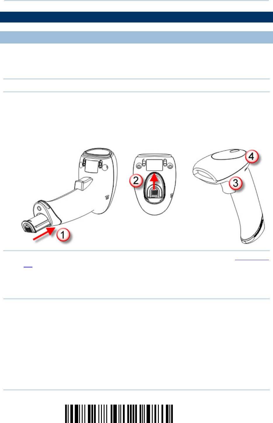
When you first receive the package, the rechargeable battery is stored separately from
the scanner. Insert the battery into the scanner first so that it can be charged when
sitting in the Auto-Sense stand.
Note: Any improper handling may reduce the battery life.
1) Hold the scanner still and insert the battery into the battery compartment at the
bottom of the scanner.
2) Slide the battery latch to lock the battery in the compartment.
3) Hold down the trigger about 2 seconds to turn on the scanner.
4) The scanner will respond with a long beep and its LED will come on-off shortly.
Note: (1) To turn off the scanner, remove the battery. Refer to settings of “Auto Power
Off”.
(2) For shipping and storage purposes, save the scanner and the battery
separately. This will keep the battery in good condition for future use.
(3) When the battery charge becomes low, you will find the scanner cannot emit
scan beam and its power-on beep sounds differently.
3
Update
!
! !
!
[
[[
[
]
] ]
]
Heading 1
Heading 1 Heading 1
Heading 1
SETTING UP
SETTING UP SETTING UP
SETTING UP 3656
36563656
3656
CRADLE
CRADLECRADLE
CRADLE
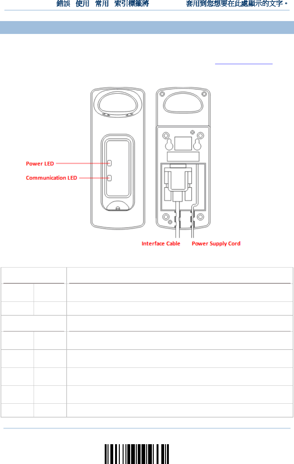
Capable of charging 1560/1562, the 3656 CRADLE stand is specifically designed for the
scanner to communicate with a host computer wirelessly. The connection between the
scanners and 3656 CRADLE is made easy and reliable. Refer to 3.1.1 Connect to . The
3656 CRADLE stand is also an Auto-Sense stand when used with the scanner set to
Auto-Sense mode.
Two LED indicators are provided for power and communications status.
Power LED
Power LEDPower LED
Power LED
Meaning
MeaningMeaning
Meaning
Red,
solid
--- Power ON
--- --- Power OFF
Communication LED
Communication LEDCommunication LED
Communication LED
Meaning
MeaningMeaning
Meaning
--- Blue,
solid
Initialize
Red,
solid
--- Failed to establish a USB connection
Red,
solid
Blue,
flashing
Serial command mode with USB Virtual COM or RS-232: wait 3 seconds for
starting a serial command
Red,
flashing
Blue,
flashing
Serial command mode with USB HID: wait 3 seconds for pressing [Num
Lock] or [Caps Lock] 5 times via keyboard
--- Blue, Wait for connection request from the scanner (Slow flash at 0.5 Hz)

4
Enter Setup
1560/1562 Series Barcode Scanner
User Guide
flashing
--- Blue,
flashing
Connected with the scanner (Fast flash at 1 Hz)
Red,
solid
Blue,
flashing
Failed to send data to host via USB Virtual COM (Fast flash at 1 Hz)
Red,
flashing
--- Enter Download Mode
5
Update
!
! !
!
[
[[
[
]
] ]
]
Heading 1
Heading 1 Heading 1
Heading 1
CHARGING THE BATTERY
CHARGING THE BATTERYCHARGING THE BATTERY
CHARGING THE BATTERY
VIA
VIA VIA
VIA 3656
36563656
3656
CRADLE
CRADLECRADLE
CRADLE
The battery may not be charged to full for shipment. When you first receive the package,
you will need to charge the battery to full before using the scanner. When using the
RS-232 cable, it takes approximately 5 hours to charge the battery to full (from the
power adaptor).
Note: Battery charging stops when the temperature drops below 0°C or exceeds 40°C. It
is recommended to charge the battery at room temperature (18°C to 25°C) for
optimal performance.
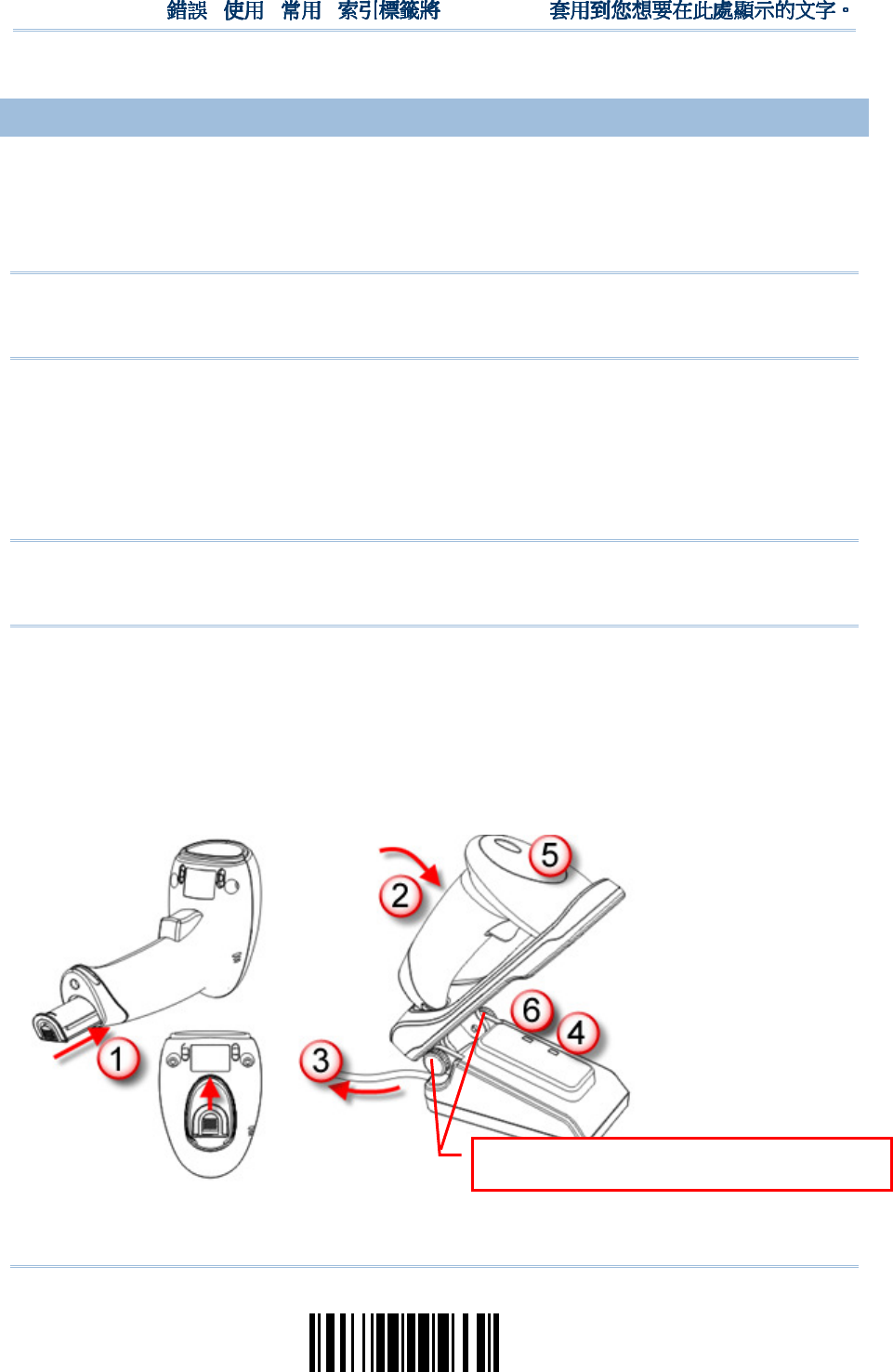
1) Install the battery to the scanner.
2) Seat the scanner in the 3656 CRADLE stand.
3) Connect the 3656 CRADLE stand to your computer or notebook via the USB or
RS-232 cable.
4) Connect the power supply cord from 3656 CRADLE to a proper power outlet.
Warning: RS-232/USB interface both require connecting the power supply cord.
When the stand is solely on USB power, the current may be insufficient for
it to function normally. You must connect the power supply cord.
5) The LED for power indication on 3656 CRADLE will become solid red.
6) The scanner LED will be flashing red during charging.
When the charging is done, the LED will turn off.
When charging error occurs, the LED will turn solid red.
7) The LED for communications on 3656 CRADLE will first become solid blue while
initializing. Refer to the table above for details on different stage of communications.
The two pivot bolts need to be tightened,
or charging error may occur.

6
Enter Setup
1560/1562 Series Barcode Scanner
User Guide
Warning: If the two pivot bolts are not tightened properly, charging error may occur.
CHARGING THE BATTERY
CHARGING THE BATTERYCHARGING THE BATTERY
CHARGING THE BATTERY
VIA CHARGER
VIA CHARGERVIA CHARGER
VIA CHARGER
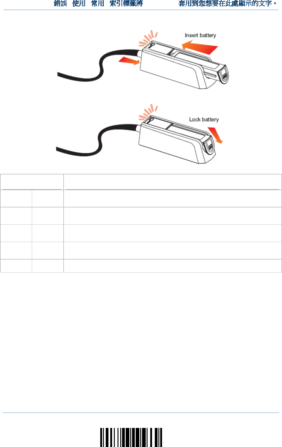
The battery charger is provided for charging the battery only. You may purchase the
charger separately. It takes approximately 3 hours to charge the battery to full.
Note: Battery charging stops when the temperature drops below 0°C or exceeds 40°C. It
is recommended to charge the battery at room temperature (18°C to 25°C) for
optimal performance.
1) Insert the battery.
2) Lock the battery.
3) Connect the power supply cord to the charger.
4) Connect the other end of the power cord to a suitable power outlet.
7
Update
!
! !
!
[
[[
[
]
] ]
]
Heading 1
Heading 1 Heading 1
Heading 1
Status LED
Status LEDStatus LED
Status LED
Meaning
MeaningMeaning
Meaning
Red,
solid
--- Charger power ON (LED on for 0.5 second)
Red,
solid
--- Charging battery
--- Green,
solid
Charging done
Red,
solid
Green,
solid
Pre-charging when battery voltage under 3V (Typical)
--- --- Power or battery not ready

8
Enter Setup
1560/1562 Series Barcode Scanner
User Guide
INSIDE THE PACKAGE
INSIDE THE PACKAGEINSIDE THE PACKAGE
INSIDE THE PACKAGE
The items included in the package may be different, depending on your order. Save the
box and packaging material for future use in case you need to store or ship the scanner.
Barcode Scanner (1560, 1560P, or 1562)
BT Base (3656 CRADLE)
Rechargeable Li-ion battery
PRODUCT HIGHLIGHTS
PRODUCT HIGHLIGHTSPRODUCT HIGHLIGHTS
PRODUCT HIGHLIGHTS
Small-form-factor and built tough to survive drop test
Extremely low power consumption
Firmware upgradeable
Supports most popular barcode symbologies, including GS1-128 (EAN-128), GS1
DataBar (RSS), etc.
Supports negative barcodes
Supports different scan modes, including Aiming Mode and Multi-Barcode Mode
User feedback via LED indicator and beeper
Beeping tone and duration programmable for Good Read
512 KB flash memory for Memory Mode operation, storing up to 32,768 scans based
on EAN-13 barcodes
Provides up to 4 KB SRAM for reserve buffer while getting out of range over a
wireless personal area network (WPAN), storing up to 256 scans based on EAN-13
barcodes
Capable of transmitting scanned data, emulating a serial cable (BT SPP) or as
keyboard input (BT HID), to a notebook computer or PDA with Bluetooth
®
wireless
technology
Programmable parameters include data output format, editing format, symbologies,
etc.
Easy configuration through ScanMaster
Easy connection through CipherConnect, available via online marketplace for mobile
devices running on Android 2.x, BlackBerry 5.x, or Windows Mobile 6.x
9
Update
!
! !
!
[
[[
[
]
] ]
]
Heading 1
Heading 1 Heading 1
Heading 1
SYMBOLOGIES
SYMBOLOGIES SYMBOLOGIES
SYMBOLOGIES SUPPORTED
SUPPORTEDSUPPORTED
SUPPORTED
Most of the popular barcode symbologies are supported, as listed below. Each can be
individually enabled or disabled. The scanner will automatically discriminate and
recognize all the symbologies that are enabled. Refer to Chapter 4 Changing Symbology
Settings for details of each symbology.
Symbologies Supported: Enable/Disable
Symbologies Supported: Enable/DisableSymbologies Supported: Enable/Disable
Symbologies Supported: Enable/Disable
Default
DefaultDefault
Default
Codabar Enabled
Code 93 Enabled
MSI Disabled
Plessey Disabled
Telepen Disabled
Code 128 Code 128 Enabled
GS1-128 (EAN-128) Enabled
ISBT 128 Enabled
Note: Starting from firmware version 1.01, ISBT 128 is enabled by default.
Code 2 of 5 Industrial 25 Enabled
Interleaved 25 Enabled
Matrix 25 Disabled
Code 3 of 9 Code 39 Enabled
Italian Pharmacode Disabled
French Pharmacode Disabled
Trioptic Code 39 Disabled
EAN/UPC EAN-8 Enabled
EAN-8 Addon 2 Disabled
EAN-8 Addon 5 Disabled
EAN-13 Enabled
EAN-13 & UPC-A Addon 2 Disabled
EAN-13 & UPC-A Addon 5 Disabled
ISBN Disabled
UPC-E0 Enabled
UPC-E1 Disabled
UPC-E Addon 2 Disabled
UPC-E Addon 5 Disabled
UPC-A Enabled

10
Enter Setup
1560/1562 Series Barcode Scanner
User Guide
GS1 DataBar
(RSS)
GS1 DataBar Omnidirectional (RSS-14) Disabled
GS1 DataBar Truncated Disabled
GS1 DataBar Stacked Disabled
GS1 DataBar Stacked Omnidirectional Disabled
GS1 DataBar Limited (RSS Limited) Disabled
GS1 DataBar Expanded (RSS Expanded) Disabled
GS1 DataBar Expanded Stacked Disabled
Code 11 Disabled

11
Update
!
! !
!
[
[[
[
]
] ]
]
Heading 1
Heading 1 Heading 1
Heading 1
13
Update
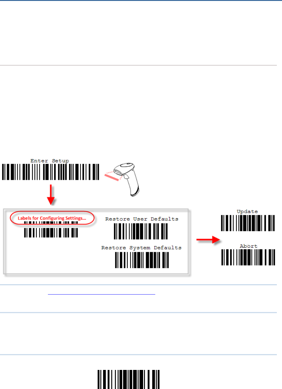
The configuration of the scanner can be done by reading the setup barcodes contained in
this manual or via the ScanMaster software.
This section describes the procedure of configuring the scanner by reading the setup
barcodes and provides some examples for demonstration.
Configuration Mode
Configuration ModeConfiguration Mode
Configuration Mode
1.
Hold down the trigger about 2 seconds to turn on the scanner. It will respond with a long beep
and its LED will come on-off shortly.
2.
Have the scanner read the “Enter Setup” barcode. It will respond with six beeps and its LED
indicator will become flashing red after reading the barcode.
3.
Have the scanner read more setup barcodes… Most of the setup barcodes are normal. The
scanner will respond with two beeps (low-high tone). For special setup barcodes, it requires
reading more than one setup barcode to complete the setting.
4.
Have the scanner read the “Update” or “Abort” barcode. It will respond with six beeps and its
LED indicator will become flashing red after reading the barcode.
5.
The scanner will restart automatically upon reading the “Update” or “Abort” barcode. It will
respond with a long beep and its LED will come on-off shortly.
Note: Refer to Appendix II Host Serial Commands for how to configure the 3656 CRADLE
stand by having the scanner read 3656 CRADLE -related setup barcodes or using
serial commands.
QUICK START
QUICK STARTQUICK START
QUICK START
14
Enter Setup
1560/1562 Series Barcode Scanner
User Guide
Work
WorkWork
Working
inging
ing
Mode
ModeMode
Mode
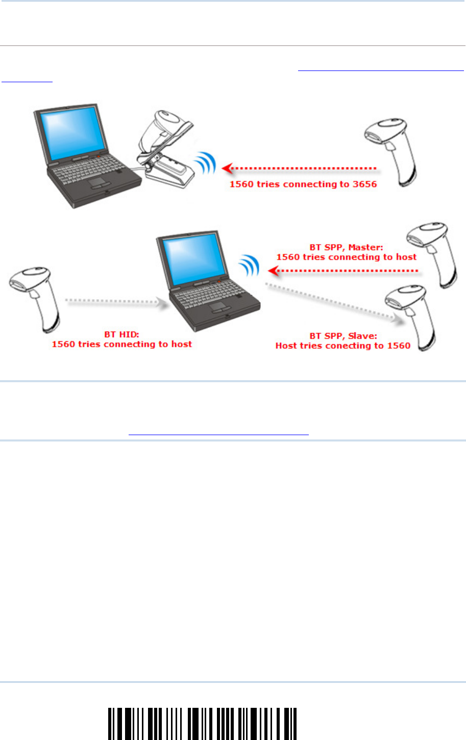
Upon powering up, the 1560/1562 scanner will try to establish a connection with 3656 CRADLE or
a computer with Bluetooth
®
wireless technology. Refer to Chapter 3 – Setting up a WPAN
Connection for details. The connection between the scanners and 3656 CRADLE is made easy and
reliable.
Note: If RS-232, USB Virtual COM or BT SPP is selected for output interface, the host can
directly send serial commands to configure the scanner. For example, run
HyperTerminal.exe and type the 6-digit command located under each setup
barcode. Refer to Appendix II Host Serial Commands.

15
Update
!
! !
!
[
[[
[
]
] ]
]
Heading 1
Heading 1 Heading 1
Heading 1
ENTER CONFIGURATION
ENTER CONFIGURATION ENTER CONFIGURATION
ENTER CONFIGURATION MODE
MODEMODE
MODE
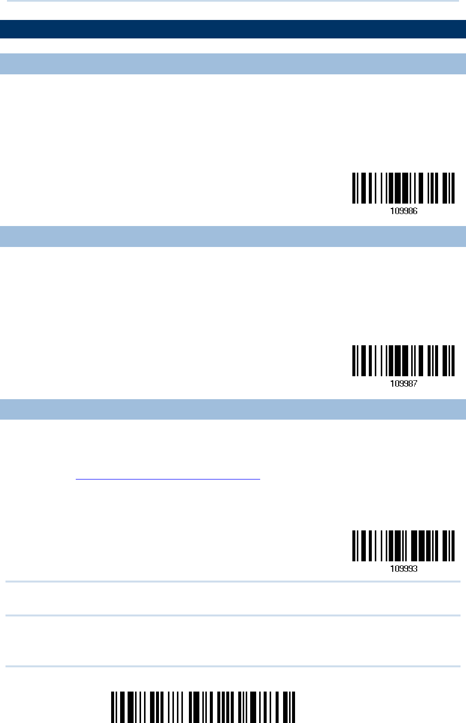
For the scanner to enter the configuration mode, you must have it read the “Enter Setup”
barcode, which can be located at the bottom of almost every even page of this manual.
The scanner will respond with six beeps and its LED indicator will become flashing red
after reading the barcode.
Enter Setup
For configuring scanner parameters, see “Read a Setup Barcode” below.
EXIT CONFIGURATION M
EXIT CONFIGURATION MEXIT CONFIGURATION M
EXIT CONFIGURATION MODE
ODEODE
ODE
For the scanner to save settings and exit the configuration mode, you must have it read
the “Update” barcode, which can be located at the bottom of almost every odd page of
this manual. If you want to exit the configuration mode without saving any changes,
have the scanner read the “Abort” barcode instead.
Just like reading the “Enter Setup” barcode, the scanner will respond with six beeps
and its LED indicator will become flashing red after reading the barcode. Wait for a
few seconds for the scanner to restart itself.
Update
Abort
16
Enter Setup
1560/1562 Series Barcode Scanner
User Guide
DEFAULT SETTINGS
DEFAULT SETTINGSDEFAULT SETTINGS
DEFAULT SETTINGS
SAVE USER SETTINGS A
SAVE USER SETTINGS ASAVE USER SETTINGS A
SAVE USER SETTINGS AS DEFAULTS
S DEFAULTSS DEFAULTS
S DEFAULTS
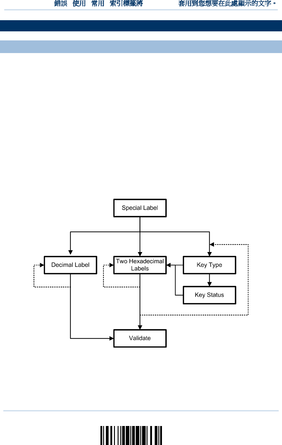
For the scanner to keep the customized settings as user defaults, you must have it read
the “Save as User Defaults” barcode. This is a normal setup barcode, and the scanner will
respond with two beeps (low-high tone).
After reading the “Update” barcode, the current settings will be saved as user
defaults.
Save as
User
Defaults
RESTORE USER DEFAULT
RESTORE USER DEFAULTRESTORE USER DEFAULT
RESTORE USER DEFAULTS
SS
S
For the scanner to restore the user defaults, which you have saved earlier, you must
have it read the “Restore User Defaults” barcode. This is a normal setup barcode, and the
scanner will respond with two beeps (low-high tone).
After reading the “Update” barcode, all the parameters of the scanner will return to
their customized values.
Restore User
Defaults
RESTORE SYSTEM DEFAU
RESTORE SYSTEM DEFAURESTORE SYSTEM DEFAU
RESTORE SYSTEM DEFAULTS
LTSLTS
LTS
For the scanner to restore the factory defaults, you must have it read the “Restore
System Defaults” barcode. This is a normal setup barcode, and the scanner will respond
with two beeps (low-high tone). For 3656 CRADLE to restore factory defaults, refer to
3656 CRADLE Setup Barcodes & Serial Commands.
After reading the “Update” barcode, all the parameters of the scanner will return to
their default values. The current connection record will be cleared as well.
Restore System
Defaults
Note: The system default value (if there is) for each setting is indicated by an asterisk
“*”.
17
Update
!
! !
!
[
[[
[
]
] ]
]
Heading 1
Heading 1 Heading 1
Heading 1
READ A SETUP
READ A SETUP READ A SETUP
READ A SETUP BARCODE
BARCODEBARCODE
BARCODE
CONFIGURE PARAMETERS
CONFIGURE PARAMETERSCONFIGURE PARAMETERS
CONFIGURE PARAMETERS
For most of the scanner parameters, only one read is required to set them to new values.
The scanner will respond with two beeps (low-high tone) when each parameter is set
successfully.
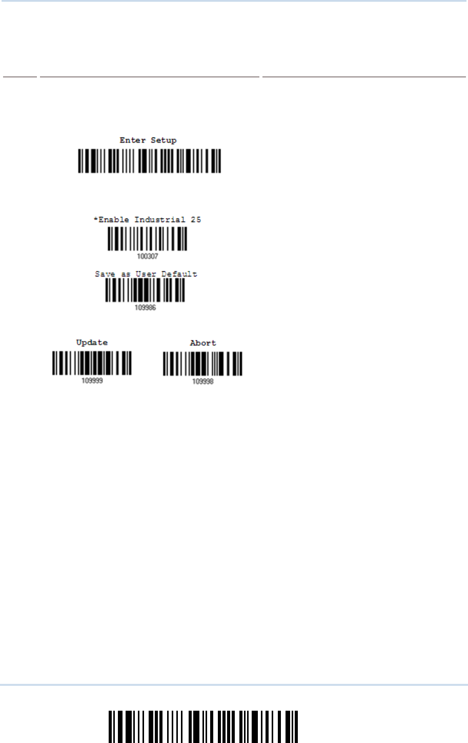
But for a number of special parameters, multiple reads are required to complete the
setting. In this case, the scanner will respond with a short beep to indicate it needs to
read more setup barcodes. These special parameters may require reading one or more
setup barcodes, such as
Numeric barcodes, say, for keyboard type, inter-character delay, length qualification
Hexadecimal barcodes, say, for character strings as prefix, suffix, etc.
When “BT HID”, “USB HID” or “Keyboard Wedge” is configured for interface, Key
Type and Key Status will then become applicable. You may decide whether or not to
change key status when “Normal Key” is selected for Key Type.
To complete the configuration of these special parameters, it requires reading the
“Validate” barcode, and the scanner will respond with two beeps (low-high tone) to
indicate the input values are validated.
18
Enter Setup
1560/1562 Series Barcode Scanner
User Guide
The example below shows how to save your settings as “User Default” so that you may
restore user defaults at a later time:
Steps
StepsSteps
Steps
Acti
ActiActi
Action
onon
on
User Feedback if Successful
User Feedback if SuccessfulUser Feedback if Successful
User Feedback if Successful
1 Power on the scanner… The scanner will respond with a long beep
(high tone) and its LED indicator will
become solid red and go off quickly.
2 Enter the Configuration Mode…
The scanner will respond with six beeps
(high-l
ow tone repeats three times), and
its LED indicator will be flashing red.
3 Read a Setup barcode…
For example,
The scanner will respond with two beeps
(low-high tone) if reading a
normal setup
barcode.
4 Exit the Configuration Mode…
OR
Same as for Enter the Configuration Mode.
5 The scanner will automatically restart itself… Same as for Power on the scanner.
* When any configuration error occurs...
The scanner will respond with one long
beep (low tone).
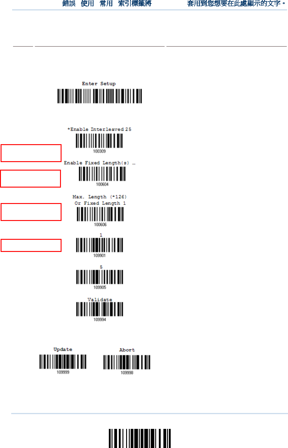
19
Update
!
! !
!
[
[[
[
]
] ]
]
Heading 1
Heading 1 Heading 1
Heading 1
The example below shows how to set numeric parameters:
Steps
StepsSteps
Steps
Action
ActionAction
Action
User Feedback if Successful
User Feedback if SuccessfulUser Feedback if Successful
User Feedback if Successful
1 Power on the scanner... The scanner will respond with a long beep
(high tone) and its LED indicator will
become solid red and go off quickly.
2 Enter the Configuration Mode…
The sca
nner will respond with six beeps
(high-
low tone repeats three times), and
its LED indicator will become flashing red.
3 Read a Setup barcode...
For example,
The scanner will respond with two beeps
(low-high tone) if reading a
normal setup
barcode.
The scanner will respond with one short
beep if reading a special setup barcode
such as “Max. Length”, indicating the
setup requires reading more barcodes.
Read the “Decimal Value” barcode(s).
Refer to Appendix IV
“Decimal
System”
The scanner will respond with two beeps
(low-high
tone) when the input values are
validated.
4 Exit the Configuration Mode…
OR
Same as for Enter the Configuration Mode.
5 The scanner will automatically restart itself… Same as for Power on the scanner.
Normal setup
barcode
Special setup
barcode
Decimal barcodes
Normal setup
barcode
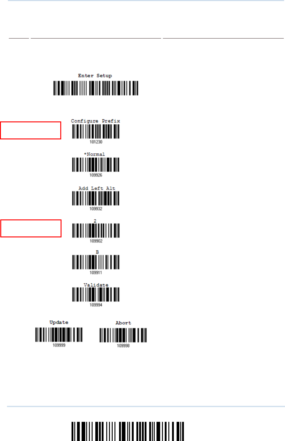
20
Enter Setup
1560/1562 Series Barcode Scanner
User Guide
The example below shows how to set string parameters:
Steps
StepsSteps
Steps
Action
ActionAction
Action
User Feedback if Successful
User Feedback if SuccessfulUser Feedback if Successful
User Feedback if Successful
1 Power on the scanner... The scanner will respond with a long beep
(high tone) and its LED indicator will
become solid red and go off quickly.
2 Enter the Configuration Mode…
The scanner will respond with six beeps
(high-
low tone repeats three times), and
its LED indicator will become flashing red.
3 Read a Setup barcode...
For example,
The scanner will respond with one short
beep if reading a special setup barcode
such as “Prefix Code”, indicating the setup
requires reading more barcodes.
When “BT HID”
, “USB HID” or “Keyboard
Wedge”
is configured for interface, Key
Type and Key Status will then become
applicable. You may decide whether
or not
to change key status
when “Normal Key”
is selected for Key Type.
Refer to Appendix III
Read the “Hexadecimal Value” barcodes
for the desired character string. For
example, read “2” and “B” for the scanner
to prefix the character “+”.
Refer to Appendix IV
“Hexadecimal
System”
The scanner will respond with two beeps
(low-high
tone) when the input values are
validated.
4 Exit the Configuration Mode…
OR
Same as for Enter the Configuration Mode.
5 The scanner will automatically restart itself… Same as for Power on the scanner.
Hexadecimal
barcodes
Special setup
barcodes
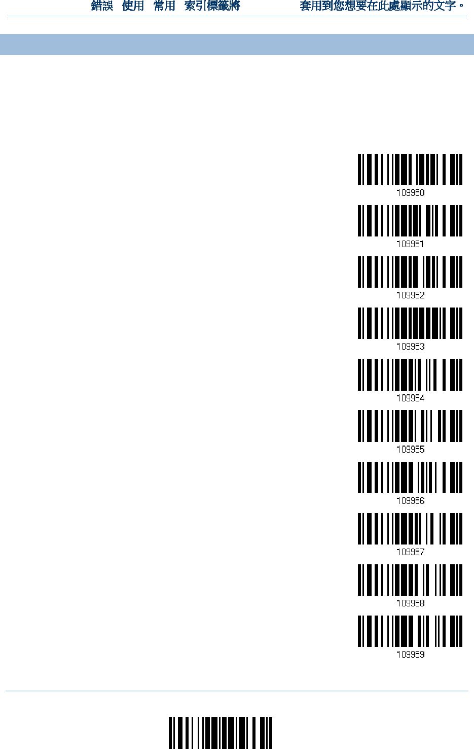
21
Update
!
! !
!
[
[[
[
]
] ]
]
Heading 1
Heading 1 Heading 1
Heading 1
LIST THE CURRENT SET
LIST THE CURRENT SETLIST THE CURRENT SET
LIST THE CURRENT SETTINGS
TINGSTINGS
TINGS
The current settings of all scanner parameters can be sent to the host computer for user
inspection. The listing includes pages as shown below. You can select the page of interest
by having the scanner read the “List Page x” barcode. The scanner will respond with two
beeps (low-high tone) and send the selected page to the host immediately.
List settings regarding Firmware Version, Serial
Number, Interface, Buzzer, and Other Scanner
Parameters
List Page 1
List settings regarding Prefix, Suffix, and Length
Code Setting
List Page 2
List settings regarding Code ID
List Page 3
List settings regarding: Readable Symbologies
List Page 4
List settings regarding Symbology Parameters
(1/3)
List Page 5
List settings regarding Symbology Parameters
(2/3)
List Page 6
List settings regarding Symbology Parameters
(3/3)
List Page 7
List settings regarding Editing Format 1
List Page 8
List settings regarding Editing Format 2
List Page 9
List settings regarding Editing Format 3
List Page 10

22
Enter Setup
1560/1562 Series Barcode Scanner
User Guide
List settings regarding Editing Format 4
List Page 11
List settings regarding Editing Format 5
List Page 12
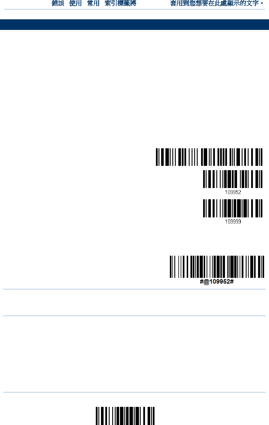
23
Update
!
! !
!
[
[[
[
]
] ]
]
Heading 1
Heading 1 Heading 1
Heading 1
CREATE ONE
CREATE ONECREATE ONE
CREATE ONE-
--
-SCAN SETUP BARCODES
SCAN SETUP BARCODESSCAN SETUP BARCODES
SCAN SETUP BARCODES
The fact is most of the scanner parameters require only one read for setting new values.
To facilitate configuring the scanner, you may create One-Scan setup barcodes for use.
The requirements of a One-Scan setup barcode are:
a prefix of the “#@” characters
the six digits of command parameters
a suffix of the “#”character
For example, the scanner needs reading three setup barcodes for the command
parameter “109952” to take effect:
Enter Setup
List Page 3
Update
Now, it requires only one read:
One-Scan Setup Barcode
for 109952
Note: The scanner will restart automatically upon reading the One-Scan setup barcode
for (1) changing the interface or (2) setting memory mode, enable or disable. It
will respond with a long beep and its LED will come on-off shortly.

24
Enter Setup
1560/1562 Series Barcode Scanner
User Guide
25
Update
This chapter will guide you through the features of the barcode scanner and how it can
function for you.
IN THIS CHAPTER
IN THIS CHAPTERIN THIS CHAPTER
IN THIS CHAPTER
1.1 Battery ...................................................................... 25
1.2 Memory ..................................................................... 31
1.3 LED Indicator ............................................................. 34
1.4 Beeper....................................................................... 36
1.5 Send “NR” to Host ....................................................... 39
1.6 Scan Modes ................................................................ 40
1.7 Scanning Timeout ....................................................... 45
1.8 Delay between Re-read ................................................ 46
1.9 Read Redundancy for All Symblogies ............................. 47
1.10 Addon Security for UPC/EAN Barcodes ......................... 48
1.11 Auto-Sense Mode (1560/1560P Only) .......................... 49
1.12 CCD Sensor Always Active (1560 Only) ........................ 52
1.13 Negative Barcodes..................................................... 52
1.14 Effective Decoding Area ............................................. 53
1.1
1.1 1.1
1.1 B
BB
BATTERY
ATTERYATTERY
ATTERY
The scanner is powered by a rechargeable 3.7 V/800 mAh Li-ion battery, and it takes
approximately 5 hours to charge the battery to full (via 3656 CRADLE from the power
adaptor). However, the charging time may vary by working condition. For intensive data
collection, you may need to purchase a spare battery for non-stop operation.
Note: See also “Power Economy”, “CCD Sensor Always Active”, “Sniff Mode”, as well as
“Low Battery Alarm”.
1.1.1
1.1.1 1.1.1
1.1.1 TURN ON/OFF
TURN ON/OFFTURN ON/OFF
TURN ON/OFF
THE SCANNER
THE SCANNERTHE SCANNER
THE SCANNER
Turn on the scanner
Turn on the scannerTurn on the scanner
Turn on the scanner…
……
…
After installing the battery, pull down the trigger for about 2 seconds. The scanner will respond
with a long beep (high tone), then the LED will become solid red and go off quickly
Turn off the scanner
Turn off the scannerTurn off the scanner
Turn off the scanner…
……
…
Remove the battery directly or let it turn off automatically in specific circumstances.
Chapter
Chapter Chapter
Chapter
1
11
1
U
UU
UNDERSTAND
NDERSTANDNDERSTAND
NDERSTANDING THE
ING THE ING THE
ING THE BARCODE
BARCODE BARCODE
BARCODE SCANNER
SCANNERSCANNER
SCANNER
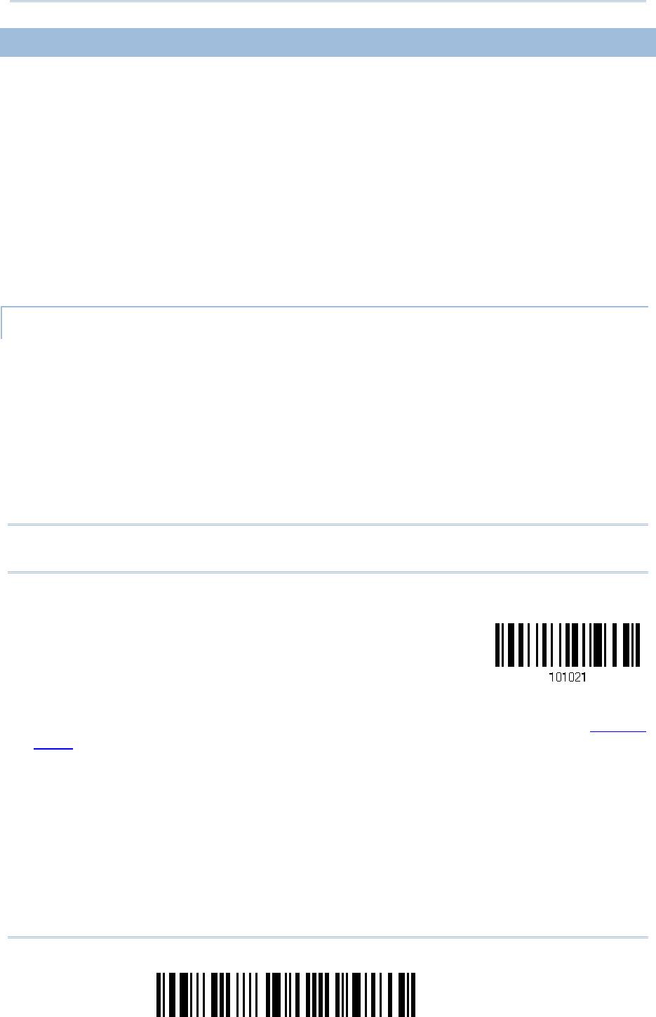
26
Enter Setup
1560/1562 Series Barcode Scanner
User
Guide
1.1.2
1.1.2 1.1.2
1.1.2 POWER E
POWER EPOWER E
POWER ECONOMY
CONOMYCONOMY
CONOMY
The scanner features “Power-Saving”, “Auto Power Off” and “Auto Power Off Ignoring
Scan Mode” giving consideration to the power issue that is generally critical for
Bluetooth-enabled devices. By the scanner’s support of power economy, its power
consumption may progress by the following transition:
1) running at full CPU speed at power-on
2) shifting to low CPU speed (Power-Saving)
3) finally shutting down automatically (Auto Power Off)
In the following content of this section, you will be guided through the configurations for
the scanner’s power economy.
1.1.2.1 POWER
1.1.2.1 POWER1.1.2.1 POWER
1.1.2.1 POWER-
--
-SAVING
SAVINGSAVING
SAVING
For the scanner to save power, you need to appoint the timing for the scanner to shift to
power-saving mode. Make the configuration that best suits your application while noting
the following points:
Power-Saving: 1~254 minutes configurable. 0= Disable.
By default, the scanner stands by at full-speed for 2 minutes after power-on and
before entering low-speed mode. If Power-Saving isn’t desired, set it to 0 to disable it.
Read the setup barcode in the following to achieve the setup.
Note: Power-Saving setting won’t take effect when the WPAN connection is established
successfully whether via BT HID or SPP.
Power-
Saving after
0~254 min. (*2)
1) Read the barcode above to enable the scanner to enter low-speed “Power-Saving”.
2) Assign the time for the scanner to enter low-speed mode by reading the “Decimal
Value” barcode on page 241. For example, read “5” for the scanner to enter
low-speed mode after idleness of 5 minutes.
3) Read the “Validate” barcode on the same page to complete this setting.
27
Update
Chapter 1
!
! !
!
[
[[
[
]
] ]
]
Heading 1
Heading 1 Heading 1
Heading 1
Note: Power-Saving won’t take effect when one of the following conditions is met:
(1) the scanner has already established a BT HID/SPP connection,
(2) the scanner is in the configuration mode,
(3) the scan mode is set to Test, Continuous or Alternate Mode,
(4) 1560 is in Auto-Sense mode and seated in the 3656 CRADLE stand, or
(5) the setting value of Power-Saving is greater than that of Auto Power Off.
1.1.2.2 AUTO POWER O
1.1.2.2 AUTO POWER O1.1.2.2 AUTO POWER O
1.1.2.2 AUTO POWER OFF
FFFF
FF
For the scanner to save power, further to setting up “Power-Saving” mode, you may also
need to enable “Auto Power Off”, which deals with a time for the scanner to automatically
power off after power-on. Make the configuration that best suits your application while
noting the following points:
Auto Power Off: 1~254 minutes configurable. 0= Disable.
1. By default, the scanner automatically shuts down 10 minutes after power-on.
2. If Auto Power Off isn’t desired, set the parameter to 0 to disable it.
3. When the scan mode is set to any of Continuous Mode, Test Mode, and Alternate
Mode, you need to enable “Auto Power Off Ignoring Scan Mode” in addition to
enabling “Auto Power Off”. See the following section 1.1.2.3 Auto Power Off
Ignoring Scan Mode to achieve auto power off.
Note: When the scanner is set to any scan mode other than Continuous Mode, Test Mode
and Alternate Mode, you can skip “Auto Power Off Ignoring Scan Mode”.
Auto Power
Off after
0~254 min. (*10)
1) Read the barcode above to enable the scanner to automatically turn off at a specified
time after power-on.
2) Assign the auto power off time by reading the “Decimal Value” barcode on page 241.
For example, read “1” and “5” for the scanner to automatically turn off after idleness
of 15 minutes.
3) Read the “Validate” barcode on the same page to complete this setting.
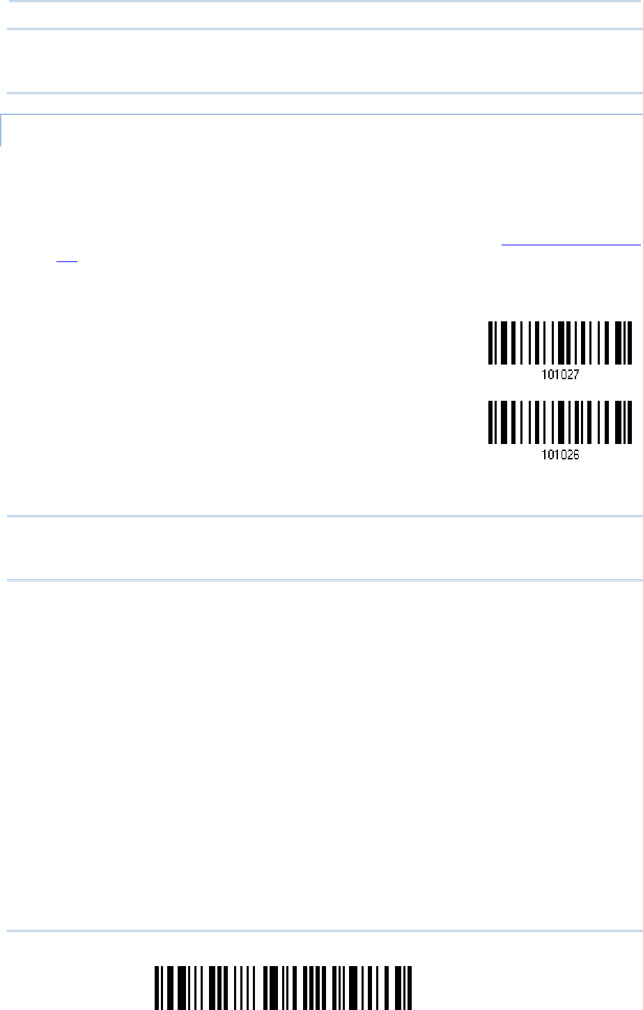
28
Enter Setup
1560/1562 Series Barcode Scanner
User
Guide
Note: “Auto Power Off” will not take effect when one of the following conditions is met:
(1) the scanner is in the configuration mode, or
(2) 1560 is in Auto-Sense mode and seated in the 3656 CRADLE stand.
1.1.2.3 AUTO POWER O
1.1.2.3 AUTO POWER O1.1.2.3 AUTO POWER O
1.1.2.3 AUTO POWER OFF IGNORING SCAN MOD
FF IGNORING SCAN MODFF IGNORING SCAN MOD
FF IGNORING SCAN MODE
EE
E
This mode is intended only for Continuous Mode, Test Mode, and Alternate Mode. To
force a scanner that is set to one of these three modes to automatically power off to save
power, you need the following settings:
1. Enable “Auto Power Off” as detailed in the foregoing section 1.1.2.2 Auto Power
Off. And set a time for the scanner to automatically power off after power-on.
2. Enable “Auto Power Off Ignoring Scan Mode” by reading the barcode below:
Enable
*Disable
Read the barcode above to enable/disable automatic power-off for Continuous Mode, Test
Mode, and Alternate Mode.
Note: “Auto Power Off Ignoring Scan Mode” only features enabling and disabling. It
doesn’t feature the setting of auto power-off time. Such setting should be
configured in the preceding setup of “Auto Power Off”.

29
Update
Chapter 1
!
! !
!
[
[[
[
]
] ]
]
Heading 1
Heading 1 Heading 1
Heading 1
1.
1.1.
1.1.3
1.3 1.3
1.3 POWER ECONOMY VS.
POWER ECONOMY VS.POWER ECONOMY VS.
POWER ECONOMY VS.
WPAN CONNECTION
WPAN CONNECTIONWPAN CONNECTION
WPAN CONNECTION
Before the scanner can communicate with the host computer, Bluetooth connection (or
WPAN connection) needs to be established. The scanner’s power economy always
accommodates itself to the establishment of the WPAN connection.
The following describes how the scanner carries out power economy before and after the
establishment of the WPAN connection:
B
BB
Bef
efef
efore establishing a WPAN connection successfully
ore establishing a WPAN connection successfullyore establishing a WPAN connection successfully
ore establishing a WPAN connection successfully…
……
…
1.
The scanner stays active for a specified period of time (2 minutes by default) for the following
scenarios. The CPU runs at full speed, and the LED blinks blue (On/Off ratio 0.5 s: 0.5 s).
(a) waiting for a connection request from the host (BT SPP Slave Mode)
(b) trying to connect to the host (BT HID or BT SPP Master Mode)
(c) trying to connect to 3656 CRADLE
2.
If the scanner fails to connect within 2 minutes, it becomes inactive to save power for the
remaining period of time (the specified “Auto Power Off” value minus 2 minutes). The CPU
starts to run at low speed, and the LED begins to blink red (On/Off ratio 0.3 s: 2.5 s).
Pull the trigger to wake up the scanner when it becomes inactive, and the scanner will become
active again.
3.
If it fails to connect again and again, and finally stays inactive until the specified Auto Power
Off time elapses, the scanner will automatically turn off in order to conserve battery power.
Pull down the trigger for about 2 seconds to turn it on again.
Note: For scenarios (a) and (b) in step 1, you may need to search for the scanner again
on your computer.
After
AfterAfter
After
establishing a WPAN connection successfully
establishing a WPAN connection successfullyestablishing a WPAN connection successfully
establishing a WPAN connection successfully…
……
…
1.
Once a WPAN connection is established successfully, the scanner will stay active for a specified
period of time (2 minutes by default) for data transmission. The CPU runs at full speed, and
the LED blinks blue (On/Off ratio 0.02 s: 3 s).
2.
If the scanner stays idle for 2 minutes (default), it will then turn inactive to save power for the
remaining period of time (the specified “Auto Power Off” value minus 2 minutes). The CPU
runs at low speed, and the LED is blinking red (On/Off ratio 0.3 s: 2.5 s).
Pull the trigger to wake up the scanner when it becomes inactive, then the scanner will stay
active again.
For BT HID or SPP, the scanner automatically shuts down after the configured “Auto Power
Off” time without the transition from full CPU speed to low CPU speed. However, when
connecting with 3656 CRADLE, the scanner will go through the transition in order to save
power.
3.
If the scanner first becomes idle and finally stays inactive until the specified Auto Power Off
time is up, the scanner will automatically turn off in order to conserve battery power. You will
hear three short beeps, tone descending from high to low.
Pull down the trigger for about 2 seconds to turn it on again.
For BT HID, the scanner resumes the connection with the host upon powering on again, as
long as the host application is running. You will hear three short beeps, tone ascending

30
Enter Setup
1560/1562 Series Barcode Scanner
User
Guide
from low to high upon the resumption. If the scanner fails to resume the connection, it will
try every 5 seconds to re-connect to the host unless you have the scanner read the “Reset
Connection” barcode.
For BT SPP Slave Mode, the scanner waits for the host to re-connect.
For BT SPP Master Mode, the scanner resumes the connection with the host upon
powering on again as long as the host application is running. You will hear three short
beeps, tone ascending from low to high upon resumption. If the scanner fails to resume
the connection, it will try every 5 seconds to re-connect to the host unless you have the
scanner read the “Reset Connection” or “Restore System Defaults” barcode.
With the use of 3656 CRADLE, the scanner tries to re-connect 3656 CRADLE unless you
turn off the scanner.
31
Update
Chapter 1
!
! !
!
[
[[
[
]
] ]
]
Heading 1
Heading 1 Heading 1
Heading 1
1.2
1.2 1.2
1.2 MEMORY
MEMORYMEMORY
MEMORY
The collected data can be sent back to a host computer one by one via the WPAN
connection or stored in flash memory when the scanner is set to Memory mode.
1.2.1
1.2.1 1.2.1
1.2.1 TRANSMIT BUF
TRANSMIT BUFTRANSMIT BUF
TRANSMIT BUFFER
FERFER
FER
By default, transmit buffer is enabled and for use when the scanner is out of range. Upon
reading a barcode successfully within range, the scanner responds with one short beep
(high tone) and its LED indicator becomes solid green and goes off quickly. However, the
host computer may not receive the data immediately if getting out of range. With the 4
KB transmit buffer, the scanner can ignore the transmission status and keep on reading
barcodes until the buffer is full.
When transmit buffer is enabled…
When transmit buffer is enabled…When transmit buffer is enabled…
When transmit buffer is enabled…
If the scanner is out of range, it will respond with two short beeps, high-low tone, upon reading a
barcode successfully.
When transmit buffer is full, the scanner will respond with one long beep (low tone) and its LED
indicator will become solid red and go off quickly. You are advised to get back to range.
When transmit buffer is disabled…
When transmit buffer is disabled…When transmit buffer is disabled…
When transmit buffer is disabled…
If the scanner is out of range, it will respond with one long beep (low tone) and its LED indicator
will become solid red and go off quickly. You are advised to get back to range.
*Enable
Disable
Note: The 4 KB transmit buffer on the scanner can hold as many as 256 scans based on
EAN-13 barcodes. Data will be cleared out once the scanner is turned off or
running out of battery power!
32
Enter Setup
1560/1562 Series Barcode Scanner
User
Guide
1.2.
1.2.1.2.
1.2.2
2 2
2 MEMORY MODE
MEMORY MODEMEMORY MODE
MEMORY MODE
The scanner keeps 512 KB flash memory for memory mode operation. When the scanner
is in memory mode, it means any real-time connection established with the host is
disabled.
Enable
*Disable
Warning: No real-time connection is allowed unless the memory mode is disabled.
Memory Data Delay
Memory Data DelayMemory Data Delay
Memory Data Delay
You may set a delay between each data record while transmitting data back to the host.
*None
250 ms
500 ms
1 sec
2 sec
3 sec
5 sec
33
Update
Chapter 1
!
! !
!
[
[[
[
]
] ]
]
Heading 1
Heading 1 Heading 1
Heading 1
8 sec
Send Data
Send DataSend Data
Send Data
The 512 KB flash memory on the scanner can store up to 32,768 scans based on EAN-13 barcodes.
When it is used up, the scanner will respond with two short beeps (high-low tone) as a warning.
You are advised to send data to the host immediately by having the scanner read the “Send Data”
barcode below. It will resume the previous WPAN connection with the host temporarily.
Send Data
Clear Data & Confirm
Clear Data & ConfirmClear Data & Confirm
Clear Data & Confirm
Even though data has been sent back to the host, the flash memory is still occupied unless you
erase the memory by having the scanner read two barcodes – “Clear Data” and “Confirm”.
1.
Read the “Clear Data” barcode to clear the flash memory.
2.
Read the “Confirm” barcode to confirm the action.
Clear Data
Confirm
1.2.3 FREE MEMORY
1.2.3 FREE MEMORY1.2.3 FREE MEMORY
1.2.3 FREE MEMORY
In memory mode, you can scan the barcode below to show the available capacity of the
flash memory in percentage terms.
Spare memory

34
Enter Setup
1560/1562 Series Barcode Scanner
User
Guide
1.3 LED INDICATOR
1.3 LED INDICATOR1.3 LED INDICATOR
1.3 LED INDICATOR
The triple-color LED on top of the scanner is used to provide user feedback. For example,
the LED becomes solid red and goes off quickly upon powering on or running out of
transmit buffer. You may tell the difference by the beeps – you will hear a long beep of
high tone when powering on the scanner, and a long beep of low tone when the transmit
buffer becomes full.
Scanner
Scanner Scanner
Scanner LED
LEDLED
LED
Meaning
MeaningMeaning
Meaning
Red,
flashing
--- ---
Charging (On/Off ratio 0.5 s: 0.5 s)
Configuration Mode (On/Off ratio 0.5 s: 0.5 s)
Red,
solid
--- --- Charging error
Red,
flashing
--- --- Flashing red (On/Off ratio 0.3 s: 2.5 s) indicates the scanner is
inactive and its CPU running at low speed to save power —
No WPAN connection is established after waiting for two
minutes
Red,
on-off
--- ---
Power on, with one long beep (high tone, LED on for 1
second)
Data saved to buffer when transmit buffer is enabled and the
scanner is out of range, with two short beeps (high-low tone)
Transmit buffer full, with one long beep (low tone)
Transmit buffer disabled, with one long beep (low tone)
Memory full in memory mode, with two short beeps (high-low
tone)
--- --- Green,
on-off
Good Read, with one short beep (high tone) and beeper pitch and
duration programmable
--- Blue,
flashing
--- First, flashing blue (On/Off ratio 0.5 s: 0.5 s) for two minutes
indicates the scanner is waiting for connection, and goes off if no
connection is established, then flashing red (On/Off ratio 0.3 s:
2.5 s) indicates the scanner is inactive.
It is ready for connection only while the LED is flashing blue —
SPP Slave: waiting host to connect
HID or SPP Master: trying to connect to host
Using 3656 CRADLE: trying to connect to 3656 CRADLE
--- Blue,
flashing
--- Flashing blue (On/Off ratio 0.1 s: 0.1 s) indicates the scanner
receives a PIN code request from host (flashing more quickly
than waiting connection).
--- Blue,
flashing
--- Flashing blue (On/Off ratio 0.02 s: 3 s) indicates the scanner has
established a WPAN connection successfully.
--- Blue,
flashing
Green,
flashing
Flashing blue and green (On/Off ratio 0.1 s: 0.1 s) indicates an
error occurs while entering the PIN code. Press the trigger to get
ready for re-connecting.
35
Update
Chapter 1
!
! !
!
[
[[
[
]
] ]
]
Heading 1
Heading 1 Heading 1
Heading 1
1.3.
1.3.1.3.
1.3.1
11
1
GOOD READ LED
GOOD READ LEDGOOD READ LED
GOOD READ LED
*Enable
Good Read LED
Disable
Good Read LED
1.3.2 GOOD READ LED
1.3.2 GOOD READ LED 1.3.2 GOOD READ LED
1.3.2 GOOD READ LED DURATION
DURATIONDURATION
DURATION
By default, the Good Read LED stays on for 40 milliseconds. Specify a value, ranging
from 1 to 254 in units of 10 milliseconds.
Good Read LED
Time-out after
0.01~2.54 sec.
(*40 ms)
1) Read the barcode above to specify the time interval before the Good Read LED goes
off.
2) Read the “Decimal Value” barcode on page 241. For example, read “1” and “5” for the
Good Read LED to go off after 150 milliseconds.
3) Read the “Validate” barcode on the same page to complete this setting.
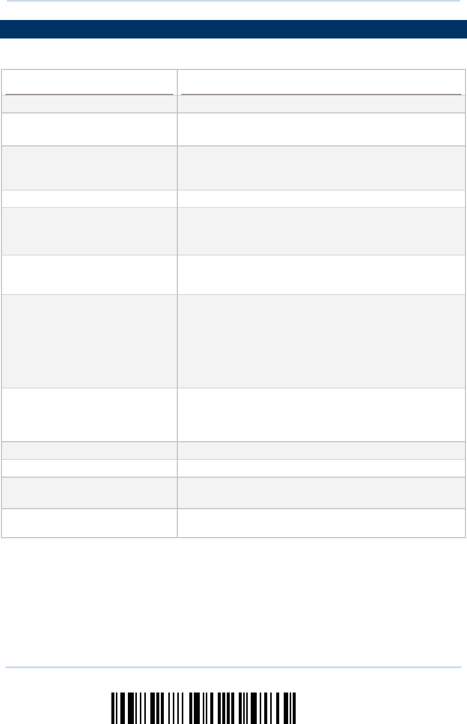
36
Enter Setup
1560/1562 Series Barcode Scanner
User
Guide
1.
1.1.
1.4
44
4
BEEP
BEEPBEEP
BEEPER
ERER
ER
The scanner has a buzzer to provide user feedback in various operating conditions.
Beeping
BeepingBeeping
Beeping
Meaning
MeaningMeaning
Meaning
One long beep, high tone Power on, with red LED on (1 second) and off quickly
One short beep, high tone
Programmable, default to 4 KHz
Good Read, with green LED on-off quickly
Six short beeps
High-low tone repeats three
times
Enter Configuration Mode, with red LED flashing
Exit Configuration Mode
Two short beeps, low-high tone Setup barcode read successfully
One short beep, high tone
More setup barcode required
Input PIN code
Clear PIN code
One short beep, low tone More barcodes required to complete the “output sequence”
requirements of Multi-Barcode Editor, with green LED on-off
quickly (Upon completion, same as Good Read.)
One long beep, low tone
Transmit buffer full, with red LED on-off quickly
Transmit buffer disabled, with red LED on-off quickly
Configuration error (Wrong barcode…)
PIN code input error
Reject random PIN request
Fail to send data in memory mode
Two short beeps, high-low tone
Data saved to buffer when transmit buffer is enabled
and the scanner is out of range, with red LED on-off
quickly
Memory Mode – Memory full, with red LED on-off quickly
Two short beeps, high tone Low Battery Alarm
Two long beeps, high-low tone Multi-Barcode Mode – Buffer full
Three short beeps, tone ascending
from low to high
WPAN connection established, with blue LED flashing
WPAN connection resumed, with blue LED flashing
Three short beeps, tone ascending
from high to low
WPAN connection out of range or suspended

37
Update
Chapter 1
!
! !
!
[
[[
[
]
] ]
]
Heading 1
Heading 1 Heading 1
Heading 1
1.4.
1.4.1.4.
1.4.1
11
1
BEEPER
BEEPER BEEPER
BEEPER VOLUME
VOLUMEVOLUME
VOLUME
Mute
Minimum Volume
Medium Volume
*Maximum Volume
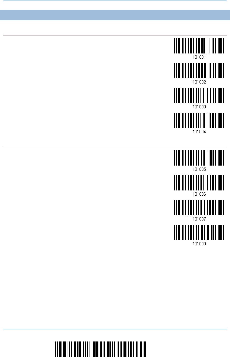
38
Enter Setup
1560/1562 Series Barcode Scanner
User
Guide
1.4.
1.4.1.4.
1.4.2
22
2
GOOD READ BEEP
GOOD READ BEEPGOOD READ BEEP
GOOD READ BEEP
Frequency
FrequencyFrequency
Frequency
8 kHz
*4 kHz
2 kHz
1 kHz
Duration
DurationDuration
Duration
*Shortest
Shorter
Longer
Longest
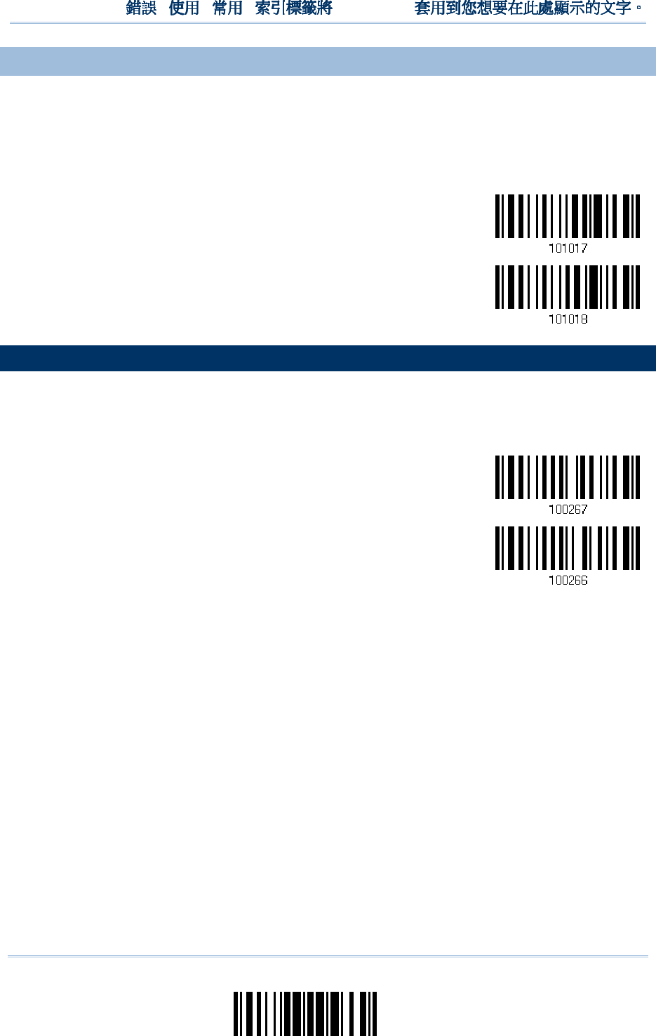
39
Update
Chapter 1
!
! !
!
[
[[
[
]
] ]
]
Heading 1
Heading 1 Heading 1
Heading 1
1.4.
1.4.1.4.
1.4.3
33
3
LOW BATTERY ALARM
LOW BATTERY ALARMLOW BATTERY ALARM
LOW BATTERY ALARM
By default, it will activate the beeper to give a warning when the battery charge gets low.
In order to prevent data loss, you are advised to replace the battery immediately when
you hear two short beeps (high tone).
No Alarm
*Low Battery Alarm
1.5
1.51.5
1.5
SEND “NR” TO HOST
SEND “NR” TO HOSTSEND “NR” TO HOST
SEND “NR” TO HOST
The scanner can send the “NR” string to the host to notify the No Read event.
Enable
*Disable
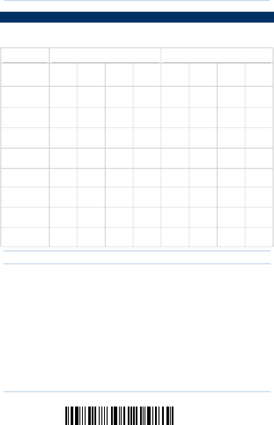
40
Enter Setup
1560/1562 Series Barcode Scanner
User
Guide
1.
1.1.
1.6
66
6
SCAN MODES
SCAN MODESSCAN MODES
SCAN MODES
Different scan modes are supported – select the scan mode that best suits the
requirements of a specific application. Refer to the comparison table below.
Scan Mode
Scan ModeScan Mode
Scan Mode
Start to Scan
Start to ScanStart to Scan
Start to Scan
Stop Scanning
Stop ScanningStop Scanning
Stop Scanning
Always Press
trigger
once
Hold
trigger
Press
trigger
twice
Release
trigger
Press
trigger
once
Barcode
being
read
Timeout
Continuous
mode
Test mode
Laser mode
Auto Off mode
Auto Power Off
mode
Alternate mode
Aiming mode
Multi-Barcode
mode
Note: By default, the scan mode is set to Laser mode.
41
Update
Chapter 1
!
! !
!
[
[[
[
]
] ]
]
Heading 1
Heading 1 Heading 1
Heading 1
1.
1.1.
1.6
66
6.
..
.1
11
1
CONTINUOUS MODE
CONTINUOUS MODECONTINUOUS MODE
CONTINUOUS MODE
The scanner is always scanning.
After a successful decoding, the removal of barcode is required. It is not allowed to
proceed to decode until the decoding delay time has passed.
To decode the same barcode repeatedly, move away the barcode and put it back
again and again for scanning.
Note: Refer to “Delay between Re-read”.
Continuous Mode
Decoding Delay
Decoding DelayDecoding Delay
Decoding Delay
Set the time interval between each decoding.
*Disable
0.5 sec
1 sec
2 sec
1.
1.1.
1.6
66
6.2
.2.2
.2
TEST MODE
TEST MODETEST MODE
TEST MODE
The scanner is always scanning.
Capable of decoding the same barcode repeatedly without removing it, for testing
purpose.
Test Mode
42
Enter Setup
1560/1562 Series Barcode Scanner
User
Guide
1.
1.1.
1.6
66
6.
..
.3
33
3
LASER MODE
LASER MODELASER MODE
LASER MODE
The scanner will start scanning once the trigger is held down.
The scanning won’t stop until (1) a barcode is decoded, (2) the pre-set timeout
expires, or (3) you release the trigger.
Note: Refer to “Scanning Timeout”.
*Laser Mode
1.
1.1.
1.6
66
6.
..
.4
44
4
AUTO OFF MODE
AUTO OFF MODEAUTO OFF MODE
AUTO OFF MODE
The scanner will start scanning once the trigger is pressed.
The scanning won’t stop until (1) a barcode is decoded, and (2) the pre-set timeout
expires.
Note: Refer to “Scanning Timeout”.
Auto Off Mode
1.
1.1.
1.6.
6.6.
6.5
55
5
AUTO POWER OFF MODE
AUTO POWER OFF MODEAUTO POWER OFF MODE
AUTO POWER OFF MODE
The scanner will start scanning once the trigger is pressed.
The scanning won’t stop until the pre-set timeout expires, and, the pre-set timeout
period re-counts after each successful decoding.
Note: Refer to “Delay between Re-read” and “Scanning Timeout”.
Auto Power Off Mode
43
Update
Chapter 1
!
! !
!
[
[[
[
]
] ]
]
Heading 1
Heading 1 Heading 1
Heading 1
1.6.6 ALTERNATE MODE
1.6.6 ALTERNATE MODE1.6.6 ALTERNATE MODE
1.6.6 ALTERNATE MODE
The scanner will start scanning once the trigger is pressed
The scanning won't stop until you press the trigger again.
Alternate Mode
1.
1.1.
1.6
66
6.
..
.7
77
7
AIMING MODE
AIMING MODEAIMING MODE
AIMING MODE
The scanner will aim at a barcode once the trigger is pressed, and start scanning when
the trigger is pressed again within one second.
The scanning won't stop until (1) a barcode is decoded, and (2) the pre-set timeout
expires.
Aiming Mode
Aiming Timeout
Aiming TimeoutAiming Timeout
Aiming Timeout
You can limit the aiming time interval (1~15). By default, the scanner time-out is set to 1 second.
Aiming Time-out
after 1~15 sec.
(*1)
1.
Read the barcode above to specify the time interval before aiming ends. (It is set to 1 by
default.)
2.
Read the “Decimal Value” barcode on page 241. For example, read “1” and “0” for the scanner
to automatically shut down after idleness for 10 seconds.
3.
Read the “Validate” barcode on the same page to complete this setting.

44
Enter Setup
1560/1562 Series Barcode Scanner
User
Guide
1.
1.1.
1.6
66
6.
..
.8
88
8
MULTI
MULTIMULTI
MULTI-
--
-BARCODE MODE
BARCODE MODEBARCODE MODE
BARCODE MODE
The scanner will be scanning as long as the trigger is held down, capable of decoding one
single barcode, as well as multiple unique barcodes one at a time. While decoding a
bunch of unique barcodes, if a barcode is decoded twice, its subsequent decoding will be
ignored and the scanner is expecting another unique barcode.
The scanning won't stop until you release the trigger.
Multi-Barcode Mode
Note: (1) A barcode is considered unique when its Code Type or data is different from
others.
(2) Multi-Barcode Mode has nothing to do with the Multi-Barcode Editor.

45
Update
Chapter 1
!
! !
!
[
[[
[
]
] ]
]
Heading 1
Heading 1 Heading 1
Heading 1
1.
1.1.
1.7
77
7
SCANN
SCANNSCANN
SCANNING
INGING
ING
TIMEOUT
TIMEOUTTIMEOUT
TIMEOUT
Specify the scanning time interval (1~254 sec.; 0= Disable) when the scan mode is set
to any of the following –
Laser mode
Auto Off mode
Auto Power Off mode
Aiming mode
Scanner Time-out
after 0~254 sec.
(*10)
1) Read the barcode above to specify the time interval before the scan engine times out.
2) Read the “Decimal Value” barcode on page 241. For example, read “1” and “5” for the
scanner to automatically shut down after idleness of 15 seconds.
3) Read the “Validate” barcode on the same page to complete this setting.
46
Enter Setup
1560/1562 Series Barcode Scanner
User
Guide
1.
1.1.
1.8
88
8
DELAY BETWEEN RE
DELAY BETWEEN REDELAY BETWEEN RE
DELAY BETWEEN RE-
--
-READ
READREAD
READ
This is also referred to as the “Blocking Time”, which is used to prevent the scanner from
accidentally reading the same barcode twice when the scan mode is set to any of the
following –
Continuous mode
Auto Power Off mode
Alternate mode
100 ms
200 ms
*400 ms
800 ms
1 sec
2 sec
3 sec
5 sec
47
Update
Chapter 1
!
! !
!
[
[[
[
]
] ]
]
Heading 1
Heading 1 Heading 1
Heading 1
1.
1.1.
1.9
99
9
READ REDUNDA
READ REDUNDAREAD REDUNDA
READ REDUNDANCY FOR ALL SYMBLOGI
NCY FOR ALL SYMBLOGINCY FOR ALL SYMBLOGI
NCY FOR ALL SYMBLOGIES
ESES
ES
Select the level of reading security. For example,
If “No Redundancy” is selected, one successful decoding will make the reading valid
and induce the “READER Event”.
If “Three Times” is selected, it will take a total of four consecutive successful
decoding of the same barcode to make the reading valid. The higher the reading
security is (that is, the more redundancy the user selects), the slower the reading
speed gets.
It is obvious that the more redundancy you select, the higher the reading security is, and
thus, the slower the reading speed becomes. You will have to compromise between
reading security and decoding speed.
*No Redundancy
One Time
Two Times
Three Times
48
Enter Setup
1560/1562 Series Barcode Scanner
User
Guide
1.1
1.11.1
1.10
00
0
ADDON SECURITY FOR
ADDON SECURITY FORADDON SECURITY FOR
ADDON SECURITY FOR
UPC/EAN BARCODES
UPC/EAN BARCODESUPC/EAN BARCODES
UPC/EAN BARCODES
The scanner is capable of decoding a mix of UPC/EAN barcodes with and without addons.
The read redundancy (0~30 times) allows changing the number of times to decode a
UPC/EAN barcode before transmission. The more redundancy you select, the higher the
reading security is, and thus, the slower the reading speed becomes. You will have to
compromise between reading security and decoding speed.
Note: UPC/EAN Addon 2 and Addon 5 must be enabled individually for this setting to
take effect.
Addon Security Level
(*0~30)
1) Read the barcode above to specify the read redundancy for UPC/EAN barcodes. (It is
set to 0 by default.)
2) Read the “Decimal Value” barcode on page 241. For example, read “1” and “2” for the
scanner to re-read the barcode for 12 times.
3) Read the “Validate” barcode on the same page to complete this setting.
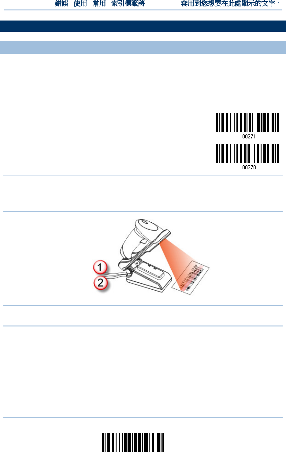
49
Update
Chapter 1
!
! !
!
[
[[
[
]
] ]
]
Heading 1
Heading 1 Heading 1
Heading 1
1.11 AUTO
1.11 AUTO1.11 AUTO
1.11 AUTO-
--
-SENSE MODE (1560
SENSE MODE (1560SENSE MODE (1560
SENSE MODE (1560/1560P
/1560P/1560P
/1560P
ONLY)
ONLY)ONLY)
ONLY)
1.11.1 BEHAVIOR OF 1
1.11.1 BEHAVIOR OF 11.11.1 BEHAVIOR OF 1
1.11.1 BEHAVIOR OF 1560
560560
560
For 1560, this mode is available when you seat the scanner in the Auto-sense stand and
scan the Enable barcode. When you enable this mode, it will force the scanner to apply
Laser mode as the scan mode. However, it works slightly different from the original Laser
mode. Now the scanner will be expecting barcodes as long as it is seated in the
Auto-sense stand, as shown below. Whenever a barcode is brought within range, the
scanner will be able to decode it.
Enable
*Disable
Note: Enabling Auto-sense will force the scanner into Laser mode. To stop this mode,
you may remove the scanner from the stand or have the scanner read the
“Disable (Auto-sense)” barcode above. It will then return to Laser mode. If Laser
mode is not desired, proceed to select a scan mode best suits your application.
Note: To get Auto-sense mode work, you must connect both the power supply cord and
the interface cable to the stand; supplying the only USB power is insufficient.
50
Enter Setup
1560/1562 Series Barcode Scanner
User
Guide
1.11.2 BEHAVIOR OF 1
1.11.2 BEHAVIOR OF 11.11.2 BEHAVIOR OF 1
1.11.2 BEHAVIOR OF 1560P
560P560P
560P
For 1560P, Auto-sense is only available when the scanner is working in Laser Mode.
1560P will be expecting barcodes as long as it is seated in the Auto-sense stand.
Whenever a barcode is brought within range, the scanner will be able to decode it.
To stop this mode, just remove the scanner from the stand.
*Enable
Disable
You can determine the occasion for decoding destination barcodes. As the setting
barcodes shown below, “Detection By Barcode” means when an object is judged a
barcode, the scanner decodes the destination barcode. “Detection by Motion” means
when an object is detected moving, the scanner decodes the destination barcode.
*Detection By
Barcode
Detection By Motion
Besides, users can determine the auto-sense detection level ranging from 0 to 7 (default
value is set to 4; greater number means higher detection sensitivity) when the scanner is
seated in the stand and set in the “Detection By Motion” mode.
Auto-sense
Detection Level 0~7
(*4)
1) Read the barcode above to specify the Auto-sense Detection level.
2) Read the “Decimal Value” barcode on page 241. For example, read “1” to set the
Auto-sense Detection Level on 1.
3) Read the “Validate” barcode on the same page to complete this setting.
51
Update
Chapter 1
!
! !
!
[
[[
[
]
] ]
]
Heading 1
Heading 1 Heading 1
Heading 1
For your convenience, 1560P is designed to power on automatically in Auto-sense mode
when you seat it in the stand connecting to the power socket. By default, this mechanism
is disabled. You have to enable it by having the scanner read the Enable barcode below.
Enable
*Disable
1.11.3 AMBIENT LIGHT
1.11.3 AMBIENT LIGHT1.11.3 AMBIENT LIGHT
1.11.3 AMBIENT LIGHT
When the ambient light is too dim to activate the sensor, you may have the scanner read
the “High Sensitivity” barcode to improve performance. Starting from firmware version
1.23, it will emit scan beam every 300 milliseconds when “High Sensitivity” is enabled.
High Sensitivity
*Normal
Note: If the ambient light is under 100 lux, we suggest that you either add lighting or
use Continuous mode instead.
52
Enter Setup
1560/1562 Series Barcode Scanner
User
Guide
1.12 CCD SENSOR ALWA
1.12 CCD SENSOR ALWA1.12 CCD SENSOR ALWA
1.12 CCD SENSOR ALWAYS ACTIV
YS ACTIVYS ACTIV
YS ACTIVE (1560 ONLY)
E (1560 ONLY)E (1560 ONLY)
E (1560 ONLY)
This feature is used to keep the CCD sensor always active so that the scanner can decode
more efficiently. However, you may disable it in order to save battery power.
*Enable
Disable
1.1
1.11.1
1.13
33
3
NEGATIVE BARCODES
NEGATIVE BARCODESNEGATIVE BARCODES
NEGATIVE BARCODES
Normally, barcodes are printed with the color of the bars darker than that of the spaces.
But for negative barcodes, they are printed in the opposite sense just like negative films.
The spaces of negative barcodes are printed with a color darker than that of the bars.
You can configure the scanner to be able to read negative barcodes.
Enable
*Disable
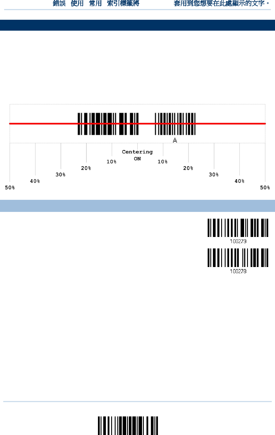
53
Update
Chapter 1
!
! !
!
[
[[
[
]
] ]
]
Heading 1
Heading 1 Heading 1
Heading 1
1.
1.1.
1.14
1414
14
EFFECTIVE DECODING A
EFFECTIVE DECODING AEFFECTIVE DECODING A
EFFECTIVE DECODING AREA
REAREA
REA
By default, the effective decoding area is 100% covered by the scanned area. However,
you may narrow down the decoding area to prevent reading the wrong barcode when a
number of barcodes are printed closely. The scanner will only read barcodes that appear
in the effective decoding area.
Read the barcode “Centering On” and specify the percentage to narrow down the
decoding area. For example, read “Left 10%” and then “Right 30%” for the scanner to
decode barcode “A” only.
1.
1.1.
1.14
1414
14.1 POSITIONING WINDO
.1 POSITIONING WINDO.1 POSITIONING WINDO
.1 POSITIONING WINDOW
WW
W
Centering On
*Centering Off
54
Enter Setup
1560/1562 Series Barcode Scanner
User
Guide
1.
1.1.
1.14
1414
14.2 ADJUSTING WINDOW
.2 ADJUSTING WINDOW.2 ADJUSTING WINDOW
.2 ADJUSTING WINDOW
Percentage for Left Half
Percentage for Left HalfPercentage for Left Half
Percentage for Left Half
*Left 50%
Left 40%
Left 30%
Left 20%
Left 10%
Percentage for Right Half
Percentage for Right HalfPercentage for Right Half
Percentage for Right Half
Right 10%
Right 20%
Right 30%
Right 40%
*Right 50%

55
Update
In order to establish a proper connection between your computer and the scanner, we
suggest that you follow these instructions –
1) Install the battery and hold down the trigger for about 2 seconds to turn on the
scanner.
2) Have the scanner read the “Enter Setup” barcode to enter the configuration mode.
3) Have the scanner read the associated barcodes to activate the desired interface.
See the following sections for output interfaces supported.
4) Have the scanner read the barcodes for related settings.
5) Have the scanner read the “Update” barcode to exit the configuration mode.
6) Turn on your computer or laptop and establish a WPAN connection with the scanner.
Refer to Chapter 3 – Setting up a WPAN Connection.
Note: By default, the output interface is set to “BT HID”.
IN THIS
IN THIS IN THIS
IN THIS CHAPTER
CHAPTERCHAPTER
CHAPTER
2.1 BT HID ...................................................................... 56
2.2 BT SPP Slave .............................................................. 68
2.3 BT SPP Master ............................................................ 72
2.4 Keyboard Wedge via .................................................. 77
2.5 RS-232 via ............................................................... 88
2.6 USB HID via .............................................................. 93
2.7 USB Virtual COM via ................................................ 103
Chapter
Chapter Chapter
Chapter
2
22
2
SE
SESE
SELECTING OUTPUT INTER
LECTING OUTPUT INTERLECTING OUTPUT INTER
LECTING OUTPUT INTERFACE
FACEFACE
FACE
56
Enter Setup
1560/1562 Series Barcode Scanner
User Guide
2.
2.2.
2.1
11
1
BT
BT BT
BT HID
HIDHID
HID
For BT HID, refer to Chapter 3 – Setting up a WPAN Connection for related connection
settings. Run any text editor on your computer, and the scanned data will be transmitted
to the computer.
HID Settings
HID SettingsHID Settings
HID Settings
Defaults
DefaultsDefaults
Defaults
Keyboard Type PCAT (US)
Alphabets Layout Normal
Digits Layout Normal
Capital Lock Type Normal
Capital Lock State Off
Alphabets Transmission Case-sensitive
Digits Transmission Alphanumeric keypad
Inter-Character Delay 0 (ms)
Inter-Function Delay 0 (ms)
57
Update
Chapter 2
!
! !
!
[
[[
[
]
] ]
]
Heading 1
Heading 1 Heading 1
Heading 1
2
22
2.1
.1.1
.1.1 ACTIVATE
.1 ACTIVATE .1 ACTIVATE
.1 ACTIVATE BT
BT BT
BT HID & SELECT KEYBOAR
HID & SELECT KEYBOARHID & SELECT KEYBOAR
HID & SELECT KEYBOARD TYPE
D TYPED TYPE
D TYPE
When BT HID interface is activated, you will have to select a keyboard type to complete
this setting. By default, BT HID is activated on the scanner, and the keyboard type is set
to PCAT (US).
Activate BT HID &
Select Keyboard
Type…
1) Read the barcode above to activate BT HID and select a keyboard type.
2) Read the “Decimal Value” barcode on page 241. Refer to the table below for the
number of desired keyboard type.
3) Read the “Validate” barcode on the same page to complete this setting.
BT HID
BT HIDBT HID
BT HID
By default, the keyboard type is set to PCAT (US). The following keyboard types are supported —
No.
No.No.
No.
Keyboard Type
Keyboard TypeKeyboard Type
Keyboard Type
No.
No.No.
No.
Keyboard Type
Keyboard TypeKeyboard Type
Keyboard Type
64 PCAT (US) 72 PCAT (Spanish)
65 PCAT (French) 73 PCAT (Portuguese)
66 PCAT (German) 74 PS55 A01-2 (Japanese)
67 PCAT (Italy) 75 User-defined table
68 PCAT (Swedish) 76 PCAT (Turkish)
69 PCAT (Norwegian) 77 PCAT (Hungarian)
70 PCAT (UK) 78 PCAT (Swiss German)
71 PCAT (Belgium) 79 PCAT (Danish)

58
Enter Setup
1560/1562 Series Barcode Scanner
User Guide
2.1.2
2.1.22.1.2
2.1.2
RESET CONNECTION
RESET CONNECTIONRESET CONNECTION
RESET CONNECTION
For BT HID, you can only have the scanner connected to one computer at a time. If you
want to connect the scanner to another host, you must have it read the “Reset
Connection” barcode so that the current connection record will be cleared. Then, the
scanner will restart itself automatically. Go through the whole process in 3.2.3 Connect to
Dongle to establish a new connection.
Reset Connection
Note: The “Restore System Defaults” barcode will have the current connection record
cleared as well.
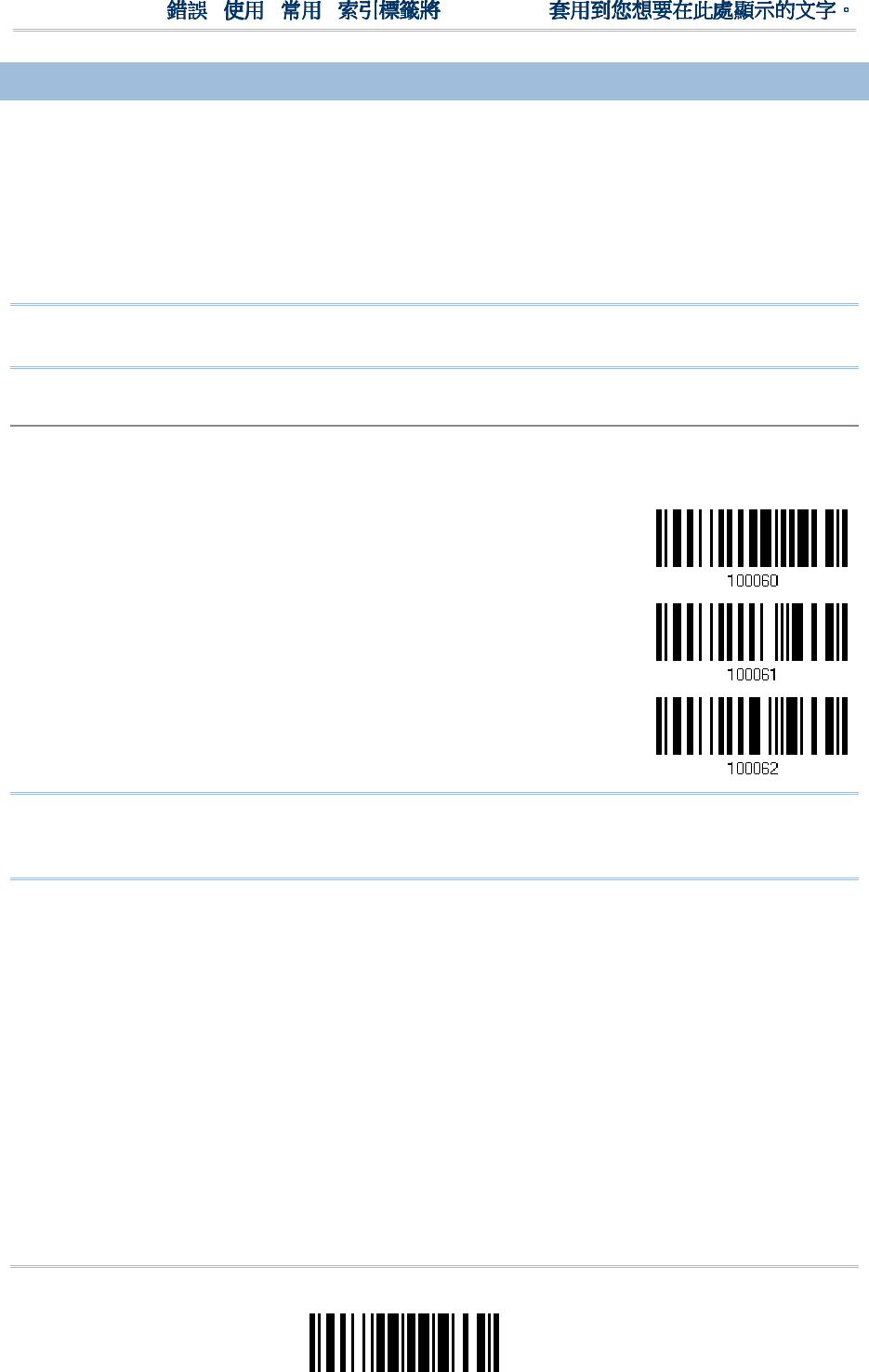
59
Update
Chapter 2
!
! !
!
[
[[
[
]
] ]
]
Heading 1
Heading 1 Heading 1
Heading 1
2.
2.2.
2.1
11
1.
..
.3
33
3
KEYBOARD SETTINGS
KEYBOARD SETTINGSKEYBOARD SETTINGS
KEYBOARD SETTINGS
Alphabets Layout
Digits Layout
Capital Lock Type
Capital Lock Setting
Alphabets Transmission
Digits Transmission
Note: BT HID does not support these functions on PDAs – (1) Capital Lock Setting: Auto
Detection (2) Digits Transmission: Numeric Key
Alphabets Layout
Alphabets LayoutAlphabets Layout
Alphabets Layout
By default, the alphabets layout is set to normal mode, also known as the standard English layout.
Select French or German keyboard layout if necessary. The scanner will make adjustments when
sending the "A", "Q", "W", "Z", "Y", and "M" characters according to this setting.
*Normal
AZERTY
QWERTZ
Note: This setting only works when the keyboard type selected is US keyboard, such as
PCAT (US). The Alphabets Layout and Digits Layout setting must match your
keyboard.
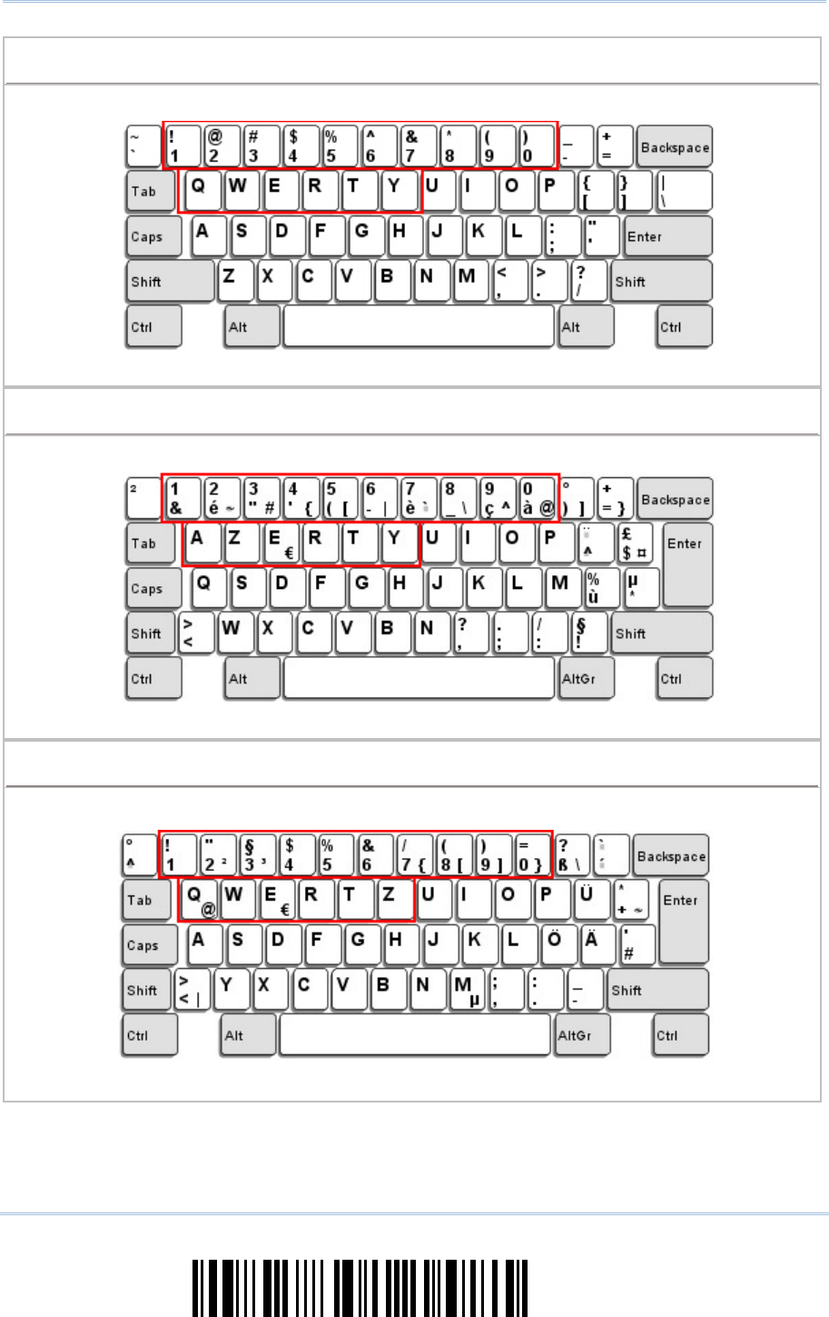
60
Enter Setup
1560/1562 Series Barcode Scanner
User Guide
US Keyboard Style
US Keyboard Style US Keyboard Style
US Keyboard Style –
––
–
Normal
NormalNormal
Normal
QWERTY layout, which is normally used in western countries.
Select “Lower Row” for the “Digits Layout” setting for the upper row is for special characters.
French Keyboard Style
French Keyboard Style French Keyboard Style
French Keyboard Style –
––
–
AZERTY
AZERTYAZERTY
AZERTY
French layout; see below for French Keyboard Style.
Select “Upper Row” for the “Digits Layout” setting for the lower row is for special characters.
German Keyboard Layout
German Keyboard Layout German Keyboard Layout
German Keyboard Layout –
––
–
QWERTZ
QWERTZQWERTZ
QWERTZ
German layout; see below for German Keyboard Style.
Select “Lower Row” for the “Digits Layout” setting for the upper row is for special characters.
61
Update
Chapter 2
!
! !
!
[
[[
[
]
] ]
]
Heading 1
Heading 1 Heading 1
Heading 1
Digits Layout
Digits LayoutDigits Layout
Digits Layout
Select a proper layout that matches the alphabets layout. The scanner will make adjustments
according to this setting.
Options
OptionsOptions
Options
Description
DescriptionDescription
Description
Normal Depends on the [Shift] key or [Shift Lock] setting
Lower Row For QWERTY or QWERTZ keyboard
Upper Row For AZERTY keyboard
*Normal
Upper Row
Lower Row
Note: This setting is to be used with the Character Substitution setting when support to
certain keyboard types (languages) is unavailable but required.
62
Enter Setup
1560/1562 Series Barcode Scanner
User Guide
Capital Lock Type & Setting
Capital Lock Type & SettingCapital Lock Type & Setting
Capital Lock Type & Setting
In order to send the alphabets with correct case, the scanner needs to know the status of Caps
Lock on the keyboard. Incorrect settings may result in reversed case of the alphabets being
transmitted.
Cap Lock T
Cap Lock TCap Lock T
Cap Lock Type
ypeype
ype
Description
DescriptionDescription
Description
Normal Normal type
Capital Lock
When enabled, the keys of alphabetic characters will be interpreted as
capital letters. However, this does not affect the number or punctuation
keys.
Shift Lock When enabled, the keys of alphabetic charact
ers will be interpreted as
capital letters. In addition, this affects the number or punctuation keys.
*Normal
Shift Lock
Capital Lock
Capital Lock State
Capital Lock StateCapital Lock State
Capital Lock State
Description
DescriptionDescription
Description
Capital Lock OFF Assuming that the status of Caps Lock on the keyboar
d is OFF,
transmitted characters are exactly the same as in the barcode (when
"case-sensitive" is selected for Alphabets Transmission).
Capital Lock ON
Assuming that the status of Caps Lock on the keyboard is ON, transmitted
characters are exactly the same as in the barcode (when "case-
sensitive"
is selected for Alphabets Transmission).
Refer to the Capital Lock Type above.
Auto Detection
The scanner will automatically detect the status of Caps Lock on the
keyboard before data is transmitted; transmitted
characters are exactly
the same as in the barcode (when "case-
sensitive" is selected for
Alphabets Transmission).
This setting is not supported on PDAs.
Auto Detect
Capital Lock ON

63
Update
Chapter 2
!
! !
!
[
[[
[
]
] ]
]
Heading 1
Heading 1 Heading 1
Heading 1
*Capital Lock OFF
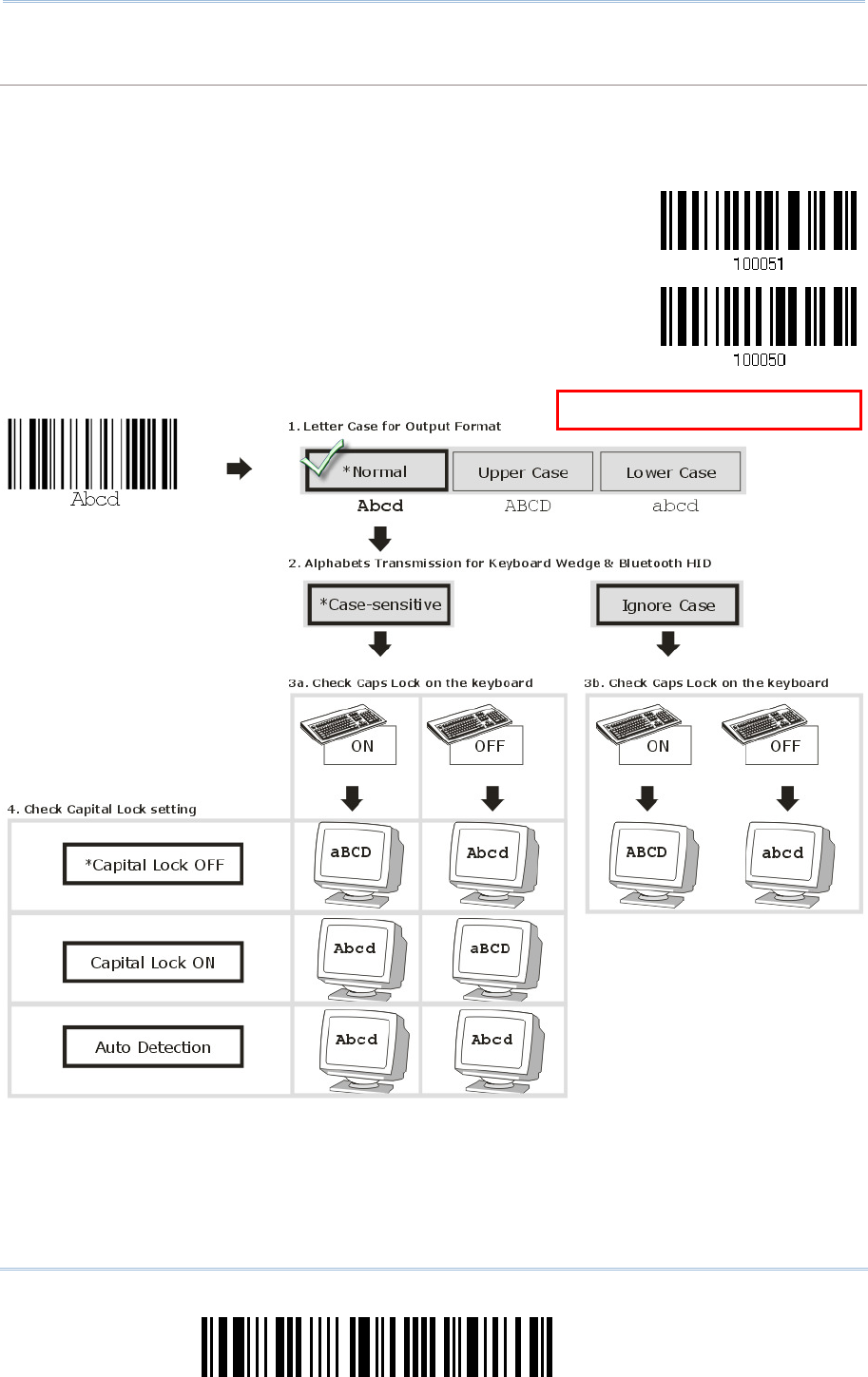
64
Enter Setup
1560/1562 Series Barcode Scanner
User Guide
Alphabets Transmission
Alphabets TransmissionAlphabets Transmission
Alphabets Transmission
By default, the alphabets transmission is case-sensitive, meaning that the alphabets will be
transmitted according to their original case, the status of Caps Lock on the keyboard, as well as the
Capital Lock setting. Select [Ignore Case] to have alphabets transmitted according to the status of
Caps Lock on the keyboard only.
Ignore Case
*Case-sensitive
Refer to 5.1 Letter Case.
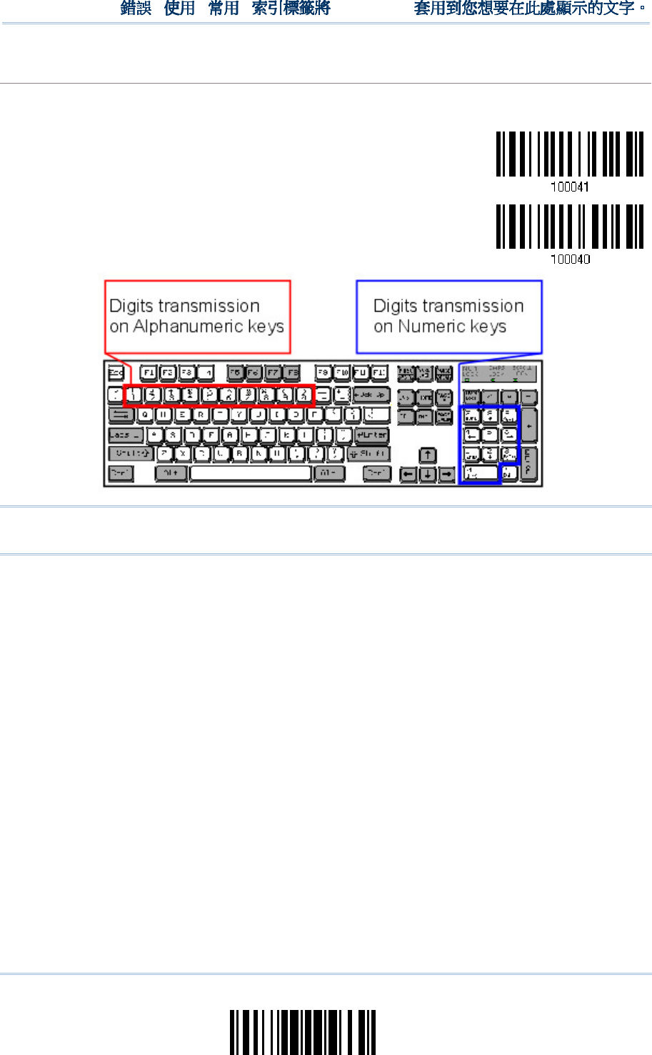
65
Update
Chapter 2
!
! !
!
[
[[
[
]
] ]
]
Heading 1
Heading 1 Heading 1
Heading 1
Digits Transmission
Digits TransmissionDigits Transmission
Digits Transmission
By default, the alphanumeric keypad is used for transmitting digits. Select “Numeric Keypad” if you
wish to use the keys on the numeric keypad.
Numeric Key
*Alphanumeric Key
Note: If you select “Numeric Keypad”, the Num Lock status of the physical keyboard
should be “ON”. This setting is not supported on PDAs.
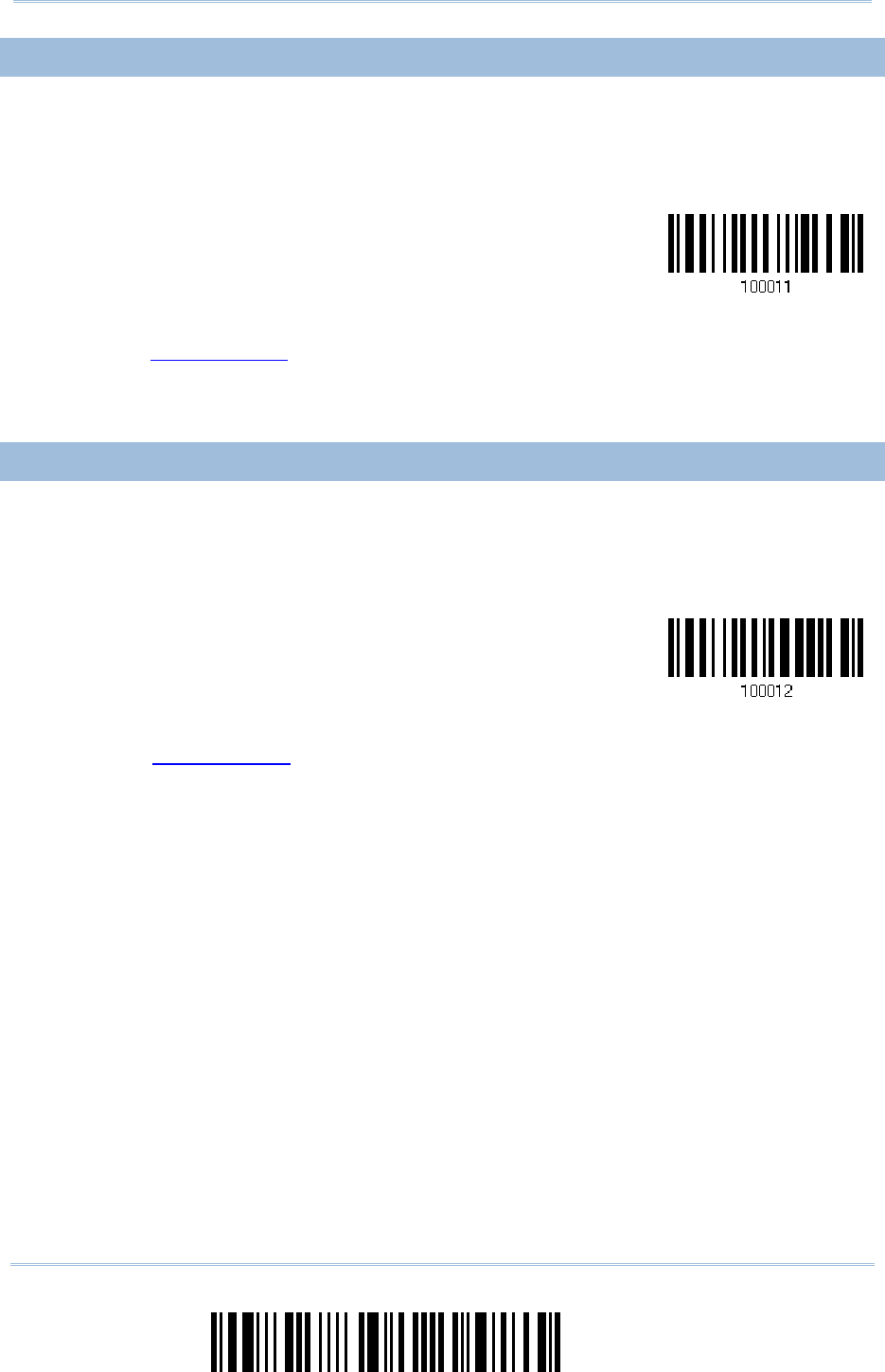
66
Enter Setup
1560/1562 Series Barcode Scanner
User Guide
2.1.4 INTER
2.1.4 INTER2.1.4 INTER
2.1.4 INTER-
--
-CHARACTER DELAY
CHARACTER DELAYCHARACTER DELAY
CHARACTER DELAY
By default, the inter-character delay is set to zero. Specify a value, ranging from 0 to
254 in units of millisecond, to match the computer response time of the keyboard
interface. Such delay time is inserted between every character being transmitted. The
longer the delay time is, the slower the transmission speed will be.
Inter-Character
Delay… (*0~254)
1) Read the barcode above to specify the inter-character delay.
2) Read the “Decimal Value” barcode on page 241 for the desired inter-character delay
(millisecond).
3) Read the “Validate” barcode on the same page to complete this setting.
2.
2.2.
2.1
11
1.
..
.5
55
5
INTER
INTERINTER
INTER-
--
-FUNCTION DELAY
FUNCTION DELAYFUNCTION DELAY
FUNCTION DELAY
By default, the inter-function delay is set to zero. Specify a value, ranging from 0 to 254
in units of millisecond, to match the computer response time of the keyboard interface.
Such delay time is inserted between every function code (0x01 ~ 0x1F) being
transmitted. The longer the delay time is, the slower the transmission speed will be.
Inter-Function
Delay… (*0~254)
1) Read the barcode above to specify the inter-function delay.
2) Read the “Decimal Value” barcode on page 241 for the desired inter-function delay
(millisecond).
3) Read the “Validate” barcode on the same page to complete this setting.

67
Update
Chapter 2
!
! !
!
[
[[
[
]
] ]
]
Heading 1
Heading 1 Heading 1
Heading 1
2.
2.2.
2.1.
1.1.
1.6
66
6
HID CHARACTER TRANSM
HID CHARACTER TRANSMHID CHARACTER TRANSM
HID CHARACTER TRANSMIT MODE
IT MODEIT MODE
IT MODE
By default, HID interface sends data to the host character by character. You may have
the scanner read the “Batch Processing” barcode to process data in batch.
Batch Processing
*By Character
Note: “By Character” transmit mode is required when working with iPhone or iPad.
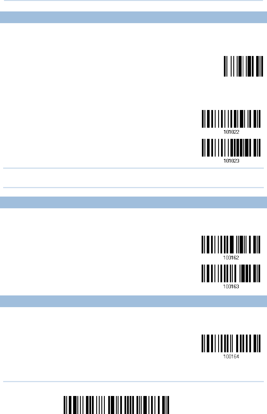
68
Enter Setup
1560/1562 Series Barcode Scanner
User Guide
2.1.
2.1.2.1.
2.1.7
77
7
KEYPAD SUPPORT FOR I
KEYPAD SUPPORT FOR IKEYPAD SUPPORT FOR I
KEYPAD SUPPORT FOR IPHONE/IPAD
PHONE/IPADPHONE/IPAD
PHONE/IPAD
When the scanner has been successfully connected to iPhone or iPad for data collection,
the onscreen keypad of iPhone/iPad will disappear by default. Have the scanner read the
“Show or Hide Keypad” barcode to show or hide the keypad if necessary.
Show or Hide Keypad
For 1560P Series scanners, read the “Use Trigger Key to Show or Hide Keypad” barcode
in advance allowing users to press the trigger key twice within 0.5 seconds to show or
hide the onscreen keypad.
Disable
*Use Trigger Key to
Show or Hide Keypad
Note: This function only works for
(1) iPhone 4 and 3GS version 4.1 or later, and (2) iPad version 4.2 or later.
2.1.8 TRANSMIT SPEED
2.1.8 TRANSMIT SPEED2.1.8 TRANSMIT SPEED
2.1.8 TRANSMIT SPEED
By default, the BT HID transmit speed is set to Fast for working in quicker transmit speed.
Users can have the scanner work in normal speed by reading the Normal barcode.
Normal
*Fast
2.1.9 BT HID SLAVE/M
2.1.9 BT HID SLAVE/M2.1.9 BT HID SLAVE/M
2.1.9 BT HID SLAVE/MASTER SWITCHING
ASTER SWITCHINGASTER SWITCHING
ASTER SWITCHING
By default, the BT HID role is set to slave. Users can have the scanner switch between
slave and master by reading the barcodes below.
*Slave

69
Update
Chapter 2
!
! !
!
[
[[
[
]
] ]
]
Heading 1
Heading 1 Heading 1
Heading 1
Master
2.1.10 BT HID AUTO
2.1.10 BT HID AUTO2.1.10 BT HID AUTO
2.1.10 BT HID AUTO-
--
-RECONNECTION (1560P
RECONNECTION (1560P RECONNECTION (1560P
RECONNECTION (1560P ONLY)
ONLY)ONLY)
ONLY)
Users can decide whether to have the scanner automatically reconnect to a paired device
after disconnection, and the occasion for reconnecting.
*Auto reconnect
immediately
Auto reconnect on
data being scanned
Auto reconnect off
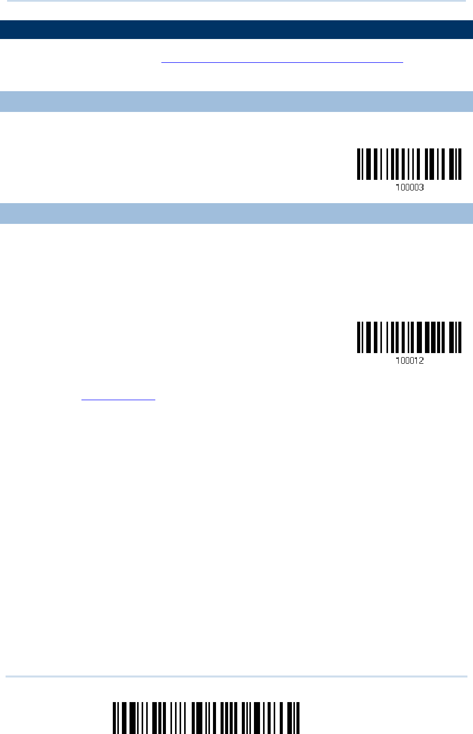
70
Enter Setup
1560/1562 Series Barcode Scanner
User Guide
2.
2.2.
2.2
22
2
BT
BT BT
BT SPP
SPPSPP
SPP
SLAVE
SLAVESLAVE
SLAVE
For BT SPP Slave, refer to Chapter 3 – Setting up a WPAN Connection for related
connection settings.
2.
2.2.
2.2
22
2.1 ACTIVATE
.1 ACTIVATE .1 ACTIVATE
.1 ACTIVATE BT
BT BT
BT SPP
SPPSPP
SPP
SLAVE MODE
SLAVE MODESLAVE MODE
SLAVE MODE
This is SPP Slave Mode.
Activate BT SPP,
Slave Mode
2.
2.2.
2.2
22
2.2 INTER
.2 INTER.2 INTER
.2 INTER-
--
-FUNCTION DELAY
FUNCTION DELAYFUNCTION DELAY
FUNCTION DELAY
By default, the inter-function delay is set to zero. Specify a value, ranging from 0 to 254
in units of millisecond, to match the computer response time of the keyboard interface.
Such delay time is inserted between every function code (0x01 ~ 0x1F) being
transmitted. The longer the delay time is, the slower the transmission speed will be.
Inter-Function
Delay… (*0~254)
1) Read the barcode above to specify the inter-function delay.
2) Read the “Decimal Value” barcode on page 241 for the desired inter-function delay
(millisecond).
3) Read the “Validate” barcode on the same page to complete this setting.
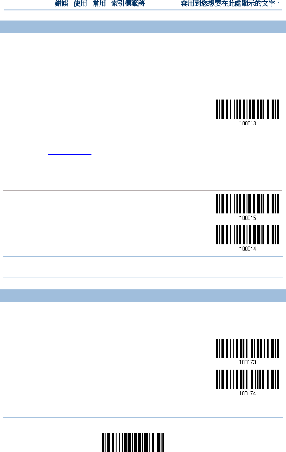
71
Update
Chapter 2
!
! !
!
[
[[
[
]
] ]
]
Heading 1
Heading 1 Heading 1
Heading 1
2.
2.2.
2.2
22
2.3
.3.3
.3
ACK/NAK TI
ACK/NAK TIACK/NAK TI
ACK/NAK TIMEOUT
MEOUTMEOUT
MEOUT
By default, the scanner sends data to the host without waiting for an ACK/NAK response
before sending more data. Specify a value, ranging from 1 to 99 in units of 0.1 second. If
no response within the specified period of time, the scanner will attempt to send the
same data two more times. If all three attempts fail without any notification, data loss
will occur.
ACK/NAK Time-out
after … (*0~99)
1) Read the barcode above to specify the time interval for the scanner to send data and
wait for a response from the host.
2) Read the “Decimal Value” barcode on page 241. For example, read “1” and “0” for the
scanner to automatically shut down after idleness of 1 second.
3) Read the “Validate” barcode on the same page to complete this setting.
ACK/NAK Error Beep
ACK/NAK Error BeepACK/NAK Error Beep
ACK/NAK Error Beep
Enable Error Beep
*Disable Error Beep
Note: We suggest enabling the error beep so that you will be notified of such data loss
and have the scanner re-read data.
2.2.4
2.2.4 2.2.4
2.2.4 BT SPP SLAVE HARDWAR
BT SPP SLAVE HARDWARBT SPP SLAVE HARDWAR
BT SPP SLAVE HARDWARE FLOW CONTROL
E FLOW CONTROLE FLOW CONTROL
E FLOW CONTROL
By default, the data sending via Bluetooth SPP doesn’t employ hardware flow control. In
some cases users may want to enable hardware flow control to prevent data loss during
transmission. Please scan the barcode below to enable/disable it.
*Disable
Enable
72
Enter Setup
1560/1562 Series Barcode Scanner
User Guide
2.3 BT SPP MASTER
2.3 BT SPP MASTER2.3 BT SPP MASTER
2.3 BT SPP MASTER
As a SPP master device, the scanner will be able to resume connection with the host
upon powering on again, as long as the host application is running. If the scanner fails to
resume connection, it will try every 5 seconds to re-connect to the host unless you have
the scanner read the “Reset Connection” or “Restore System Defaults” barcode.
For BT SPP Master, refer 3.2.2 Configure Related Settings for related connection settings.
Note: In SPP Master Mode, if the scanner fails to re-connect within the specified period
of time (2 minutes by default), the scanner will become inactive to save power.
Once the re-connection is established successfully, the scanner will not go through
transition from full CPU speed to low CPU speed even though it is idle during the
specified time interval for Auto Power Off. It will automatically turn off when the
time is up. Refer to 1.1.3 Power Economy vs. WPAN Connection.
2.
2.2.
2.3
33
3.1 ACTIVATE BT SPP
.1 ACTIVATE BT SPP.1 ACTIVATE BT SPP
.1 ACTIVATE BT SPP
MASTER MODE
MASTER MODEMASTER MODE
MASTER MODE
This is SPP Master Mode.
Activate BT SPP,
Master Mode
How to connect with the target device?
How to connect with the target device?How to connect with the target device?
How to connect with the target device?
Produce two setup barcodes for the target SPP slave device, just like what we do for 3656 CRADLE.
“Set Connection”
“MAC ID”
Note: The “MAC ID” barcode must have a prefix of two characters, either “0x” or “0X”,
followed by the real MAC address of the target device.
Usage:
1.
Read the “Activate BT SPP, Master Mode” barcode above and barcodes for connection settings,
such as authentication and preset PIN. Skip this step if no connection settings are desired.
2.
Read the “Set Connection” and “MAC ID” barcodes. The scanner will respond with one beep
upon reading each of the barcodes.
Set Connection
Prefix “0X” to target MAC address
73
Update
Chapter 2
!
! !
!
[
[[
[
]
] ]
]
Heading 1
Heading 1 Heading 1
Heading 1
Note: Read the “Set Connection” barcode first, and then the “MAC ID” barcode within 10
seconds.
Instead of producing the “MAC ID” barcode, you may have the scanner read the setup barcodes for
entering the MAC address.
Have the scanner read the “Abort” barcode to cancel the operation at any time while reading
setup barcodes for the MAC address. If the MAC address has not been completed yet, having the
scanner read the “Validate” barcode can cancel the operation as well.
Enter MAC ID in
Hexadecimal…
Usage:
1) Read the barcode above.
2) Read the “Hexadecimal System” barcode on page 242 for the desired MAC address.
3) Read the “Validate” barcode on the same page to complete this setting.
C
CC
Connect with the target device
onnect with the target deviceonnect with the target device
onnect with the target device
by scanning a single 1D setting barcode
by scanning a single 1D setting barcodeby scanning a single 1D setting barcode
by scanning a single 1D setting barcode
Users can produce a single 1D setup barcode that combines the “Set Connection” and “MAC ID” setup
commands to connect with the target device. While producing the barcode, be aware the letter
upper/lower case “SeTcOn” and the barcode must be the Code 128 symbology.
Usage:
1)
Read the “Activate Bluetooth
®
SPP, Master Mode” barcode above and barcodes for connection
settings, such as authentication and preset PIN. Skip this step if no connection settings are
desired.
2)
Read the “SeTcOnxxxxxxxxxxxx” 1D single barcode below. The scanner will respond with one
beep upon reading the barcode.
Exit SPP Master Mode
Exit SPP Master ModeExit SPP Master Mode
Exit SPP Master Mode
To stop such re-connection, read “Reset Connection” or “Restore System Defaults” barcode so that
the current connection record (= MAC ID) will be cleared. Then, the scanner will restart itself
automatically. Go through the process in 3.2.3 Connect to Dongle to establish a new WPAN
connection.
Reset Connection
74
Enter Setup
1560/1562 Series Barcode Scanner
User Guide
2.
2.2.
2.3
33
3.2 INTER
.2 INTER.2 INTER
.2 INTER-
--
-FUNCTION DELAY
FUNCTION DELAYFUNCTION DELAY
FUNCTION DELAY
By default, the inter-function delay is set to zero. Specify a value, ranging from 0 to 254
in units of millisecond, to match the computer response time of the keyboard interface.
Such delay time is inserted between every function code (0x01 ~ 0x1F) being
transmitted. The longer the delay time is, the slower the transmission speed will be.
Inter-Function
Delay… (*0~254)
1) Read the barcode above to specify the inter-function delay.
2) Read the “Decimal Value” barcode on page 241 for the desired inter-function delay
(millisecond).
3) Read the “Validate” barcode on the same page to complete this setting.
2.
2.2.
2.3
33
3.3 ACK/NAK TIMEOUT
.3 ACK/NAK TIMEOUT.3 ACK/NAK TIMEOUT
.3 ACK/NAK TIMEOUT
By default, the scanner sends data to the host without waiting for an ACK/NAK response
before sending more data. Specify a value, ranging from 1 to 99 in units of 0.1 second. If
no response within the specified period of time, the scanner will attempt to send the
same data two more times. If all three attempts fail without any notification, data loss
will occur.
ACK/NAK Time-out
after … (*0~99)
1) Read the barcode above to specify the time interval for the scanner to send data and
wait for a response from the host.
2) Read the “Decimal Value” barcode on page 241. For example, read “1” and “0” for the
scanner to automatically shut down after idleness of 1 second.
3) Read the “Validate” barcode on the same page to complete this setting.

75
Update
Chapter 2
!
! !
!
[
[[
[
]
] ]
]
Heading 1
Heading 1 Heading 1
Heading 1
ACK/NAK Error Beep
ACK/NAK Error BeepACK/NAK Error Beep
ACK/NAK Error Beep
Enable Error Beep
*Disable Error Beep
Note: We suggest enabling the error beep so that you will be notified of such data loss
and have the scanner re-read data.
76
Enter Setup
1560/1562 Series Barcode Scanner
User Guide
2.3.4 SWITCH BETWEEN
2.3.4 SWITCH BETWEEN2.3.4 SWITCH BETWEEN
2.3.4 SWITCH BETWEEN
MASTER/SLAVE MODE
MASTER/SLAVE MODEMASTER/SLAVE MODE
MASTER/SLAVE MODE
After the scanner has established a connection as a SPP slave device, you may have it
read the “Activate BT SPP, Master Mode” setup barcode to switch to SPP Master Mode.
This will result in easy and reliable re-connection, just like connecting with 3656 CRADLE.
2.3.5 BT SPP MASTER
2.3.5 BT SPP MASTER 2.3.5 BT SPP MASTER
2.3.5 BT SPP MASTER HARDWARE FLOW CONTRO
HARDWARE FLOW CONTROHARDWARE FLOW CONTRO
HARDWARE FLOW CONTROL
LL
L
By default, the data sending via Bluetooth SPP doesn’t employ hardware flow control. In
some cases users may want to enable hardware flow control to prevent data loss during
transmission. Please scan the barcode below to enable/disable it.
*Disable
Enable
2.3.6 BT SPP MASTER
2.3.6 BT SPP MASTER 2.3.6 BT SPP MASTER
2.3.6 BT SPP MASTER AUTO
AUTOAUTO
AUTO-
--
-RECONNECTION (1560P
RECONNECTION (1560P RECONNECTION (1560P
RECONNECTION (1560P ONLY)
ONLY)ONLY)
ONLY)
Users can decide whether to have the scanner automatically reconnect to a paired device
after disconnection, and the occasion for reconnecting.
*Auto reconnect
immediately
Auto reconnect on
data being scanned
Auto reconnect off
77
Update
Chapter 2
!
! !
!
[
[[
[
]
] ]
]
Heading 1
Heading 1 Heading 1
Heading 1
2
22
2.
..
.4
44
4
KEYBOARD WEDGE
KEYBOARD WEDGEKEYBOARD WEDGE
KEYBOARD WEDGE
VIA
VIA VIA
VIA 3656
36563656
3656
CRADLE
CRADLECRADLE
CRADLE
The Y cable allows you to connect the scanner via 3656 CRADLE to the keyboard input
port of PC and you may join the keyboard as well. The scanned data will be transmitted
to the host keyboard port as if it is manually entered via the keyboard. For example, run
a text editor on your computer to receive the data.
Keyboard Wedge Settings
Keyboard Wedge SettingsKeyboard Wedge Settings
Keyboard Wedge Settings
Defaults
DefaultsDefaults
Defaults
Keyboard Type PCAT (US)
Alphabets Layout Normal
Digits Layout Normal
Capital Lock Type Normal
Capital Lock State Off
Alphabets Transmission Case-sensitive
Digits Transmission Alphanumeric keypad
Alternate Composing No
Laptop Support Disable
Inter-Character Delay 0 (ms)
Inter-Function Delay 0 (ms)
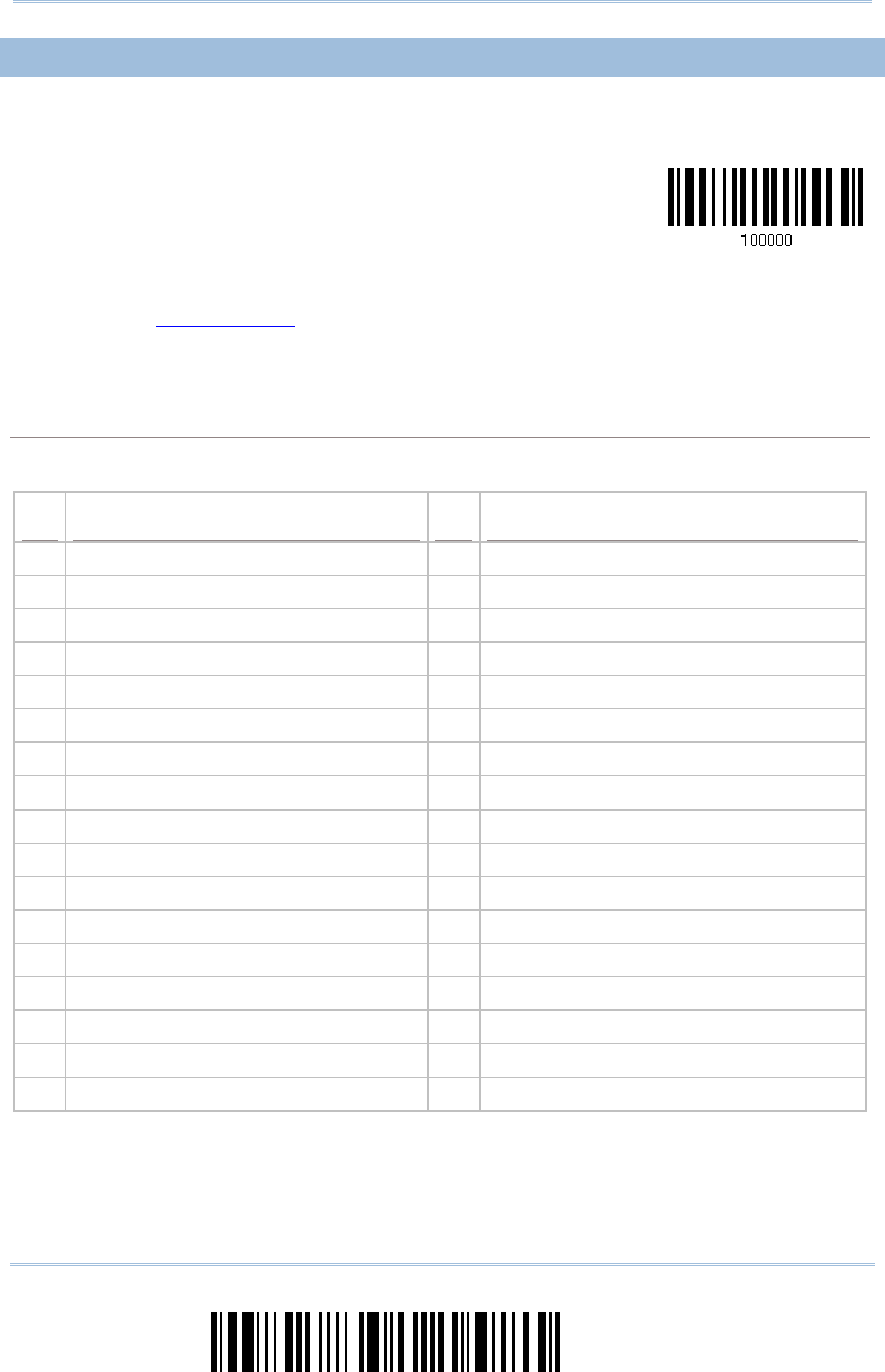
78
Enter Setup
1560/1562 Series Barcode Scanner
User Guide
2.
2.2.
2.4
44
4.1 ACTIVATE KEYBOARD
.1 ACTIVATE KEYBOARD.1 ACTIVATE KEYBOARD
.1 ACTIVATE KEYBOARD
WEDGE & SELECT KEYBO
WEDGE & SELECT KEYBOWEDGE & SELECT KEYBO
WEDGE & SELECT KEYBOARD TYPE
ARD TYPEARD TYPE
ARD TYPE
When Keyboard Wedge interface is activated, you will have to select a keyboard type to
complete this setting.
Activate 3656
CRADLE Keyboard
Wedge & Select
Keyboard Type…
1) Read this barcode above to activate Keyboard Wedge and select a keyboard type.
2) Read the “Decimal Value” barcode on page 241. Refer to the table below for the
number of desired keyboard type.
3) Read the “Validate” barcode on the same page to complete this setting.
Keyboard Wedge via
Keyboard Wedge via Keyboard Wedge via
Keyboard Wedge via 3656
36563656
3656
CRADLE
CRADLECRADLE
CRADLE
By default, the keyboard type is set to PCAT (US). The following keyboard types are supported
when using 3656 CRADLE with the keyboard wedge cable provided —
No.
No.No.
No.
Keyboard Type
Keyboard TypeKeyboard Type
Keyboard Type
No.
No.No.
No.
Keyboard Type
Keyboard TypeKeyboard Type
Keyboard Type
1 PCAT (US) 18 PS55 001-3
2 PCAT (French) 19 PS55 001-8A
3 PCAT (German) 20 PS55 002-1, 003-1
4 PCAT (Italian) 21 PS55 002-81, 003-81
5 PCAT (Swedish) 22 PS55 002-2, 003-2
6 PCAT (Norwegian) 23 PS55 002-82, 003-82
7 PCAT (UK) 24 PS55 002-3, 003-3
8 PCAT (Belgium) 25 PS55 002-8A, 003-8A
9 PCAT (Spanish) 26 IBM 3477 Type 4 (Japanese)
10 PCAT (Portuguese) 27 PS2-30
11 PS55 A01-1 28 IBM 34XX/319X, Memorex Telex 122 Keys
12 PS55 A01-2 (Japanese) 29 User-defined table
13 PS55 A01-3 30 PCAT (Turkish)
14 PS55 001-1 31 PCAT (Hungarian)
15 PS55 001-81 32 PCAT (Swiss German)
16 PS55 001-2 33 PCAT (Danish)
17 PS55 001-82
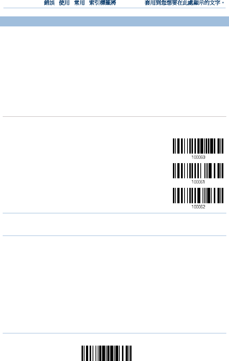
79
Update
Chapter 2
!
! !
!
[
[[
[
]
] ]
]
Heading 1
Heading 1 Heading 1
Heading 1
2.
2.2.
2.4
44
4.2 KEYBOARD SETTINGS
.2 KEYBOARD SETTINGS.2 KEYBOARD SETTINGS
.2 KEYBOARD SETTINGS
Alphabets Layout
Digits Layout
Capital Lock Type
Capital Lock Setting
Alphabets Transmission
Digits Transmission
Alternate Composing
Laptop Support
Alphabets Layout
Alphabets LayoutAlphabets Layout
Alphabets Layout
By default, the alphabets layout is set to normal mode, also known as the standard English layout.
Select French or German keyboard layout if necessary. The scanner will make adjustments when
sending the "A", "Q", "W", "Z", "Y", and "M" characters according to this setting.
*Normal
AZERTY
QWERTZ
Note: This setting only works when the keyboard type selected is US keyboard, such as
PCAT (US). The Alphabets Layout and Digits Layout setting must match your
keyboard.
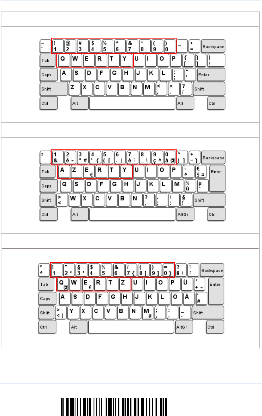
80
Enter Setup
1560/1562 Series Barcode Scanner
User Guide
US Keyboard Style
US Keyboard Style US Keyboard Style
US Keyboard Style –
––
–
Normal
NormalNormal
Normal
QWERTY layout, which is normally used in western countries.
Select “Lower Row” for the “Digits Layout” setting for the upper row is for special characters.
French Keyboard Style
French Keyboard Style French Keyboard Style
French Keyboard Style –
––
–
AZERTY
AZERTYAZERTY
AZERTY
French layout; see below for French Keyboard Style.
Select “Upper Row” for the “Digits Layout” setting for the lower row is for special characters.
German Keyboard Layout
German Keyboard Layout German Keyboard Layout
German Keyboard Layout –
––
–
QWERTZ
QWERTZQWERTZ
QWERTZ
German layout; see below for German Keyboard Style.
Select “Lower Row” for the “Digits Layout” setting for the upper row is for special characters.
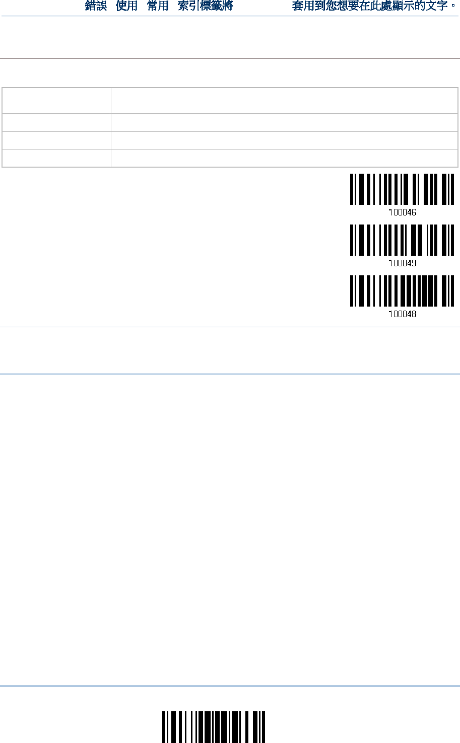
81
Update
Chapter 2
!
! !
!
[
[[
[
]
] ]
]
Heading 1
Heading 1 Heading 1
Heading 1
Digits Layout
Digits LayoutDigits Layout
Digits Layout
Select a proper layout that matches the alphabets layout. The scanner will make adjustments
according to this setting.
Options
OptionsOptions
Options
Description
DescriptionDescription
Description
Normal Depends on the [Shift] key or [Shift Lock] setting
Lower Row For QWERTY or QWERTZ keyboard
Upper Row For AZERTY keyboard
*Normal
Upper Row
Lower Row
Note: This setting is meant to be used with the Alphabets Layout; and perhaps with the
Character Substitution setting when support to certain keyboard types (languages)
is unavailable but required.
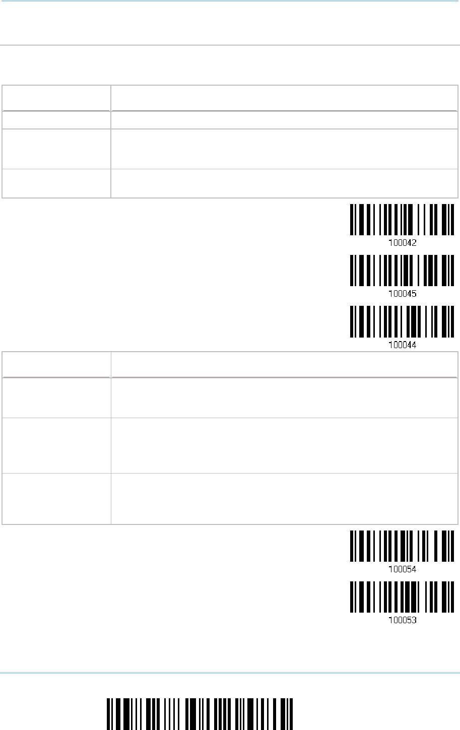
82
Enter Setup
1560/1562 Series Barcode Scanner
User Guide
Capital Lock Type & Setting
Capital Lock Type & SettingCapital Lock Type & Setting
Capital Lock Type & Setting
In order to send the alphabets with correct case, the scanner needs to know the status of Caps
Lock on the keyboard. Incorrect settings may result in reversed case of the alphabets being
transmitted.
Cap Lock Type
Cap Lock TypeCap Lock Type
Cap Lock Type
Description
DescriptionDescription
Description
Normal Normal type
Capital Lock
When enabled, the keys of alphabetic characters will be interpreted as
capital letters. However, this does not affect the number or punctuation
keys.
Shift Lock When enabled, t
he keys of alphabetic characters will be interpreted as
capital letters. In addition, this affects the number or punctuation keys.
*Normal
Shift Lock
Capital Lock
Capital Lock State
Capital Lock StateCapital Lock State
Capital Lock State
Description
DescriptionDescription
Description
Capital Lock OFF Assuming that the statu
s of Caps Lock on the keyboard is OFF,
transmitted characters are exactly the same as in the barcode (when
"case-sensitive" is selected for Alphabets Transmission).
Capital Lock ON
Assuming that the status of Caps Lock on the keyboard is ON, transmitted
characters are exactly the same as in the barcode (when "case-
sensitive"
is selected for Alphabets Transmission).
Refer to the Capital Lock Type above.
Auto Detection
The scanner will automatically detect the status of Caps Lock on the
keyboard before data
is transmitted; transmitted characters are exactly
the same as in the barcode (when "case-
sensitive" is selected for
Alphabets Transmission).
Auto Detect
Capital Lock ON

83
Update
C
hapter 2
!
! !
!
[
[[
[
]
] ]
]
Heading 1
Heading 1 Heading 1
Heading 1
*Capital Lock OFF
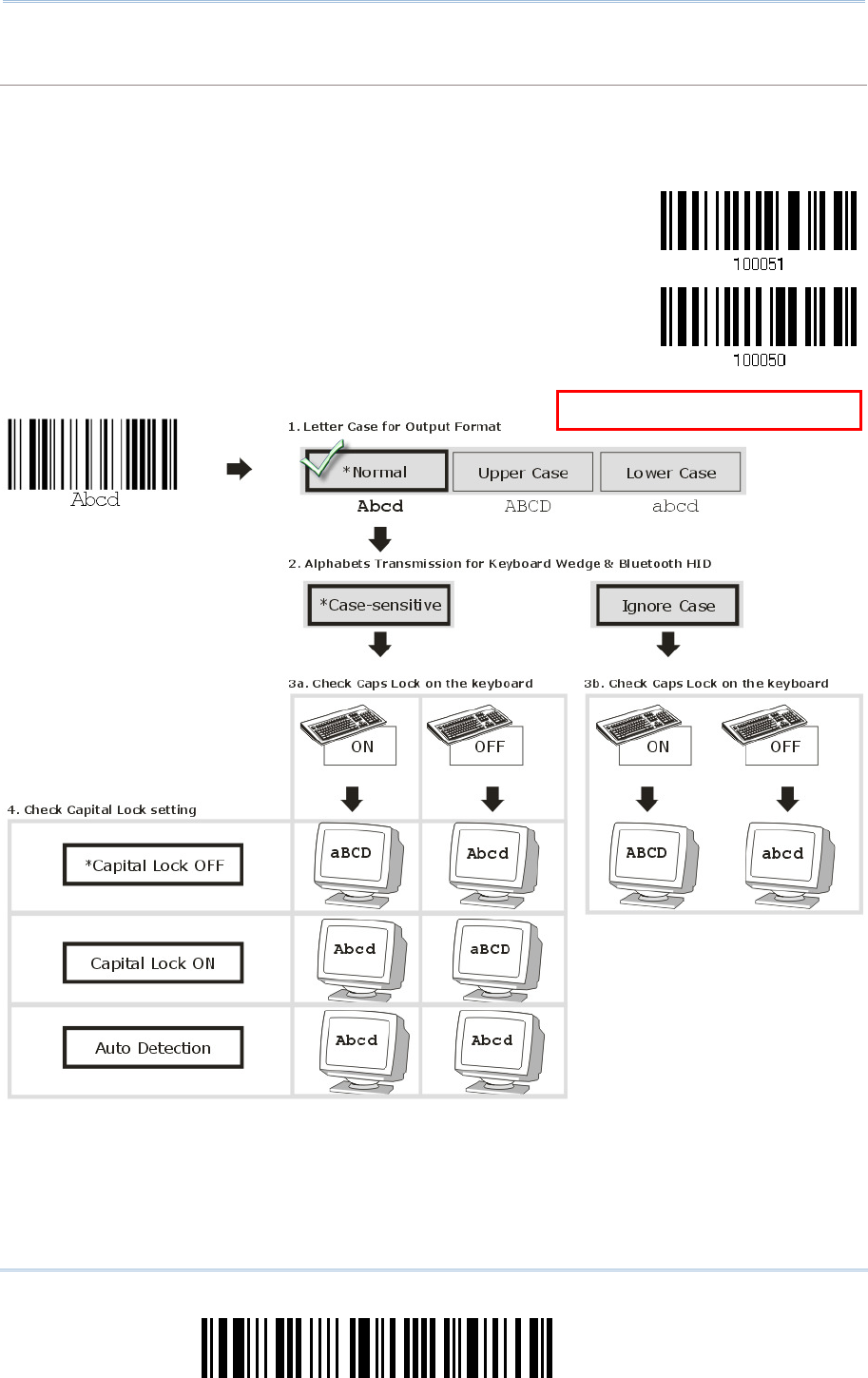
84
Enter Setup
1560/1562 Series Barcode Scanner
User Guide
Alphabets Transmission
Alphabets TransmissionAlphabets Transmission
Alphabets Transmission
By default, the alphabets transmission is case-sensitive, meaning that the alphabets will be
transmitted according to their original case, the status of Caps Lock on the keyboard, as well as the
Capital Lock setting. Select [Ignore Case] to have alphabets transmitted according to the status of
Caps Lock on the keyboard only.
Ignore Case
*Case-sensitive
Refer to 5.1 Letter Case.
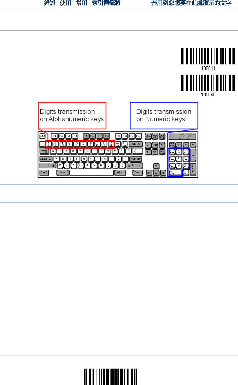
85
Update
Chapter 2
!
! !
!
[
[[
[
]
] ]
]
Heading 1
Heading 1 Heading 1
Heading 1
Digits Transmission
Digits TransmissionDigits Transmission
Digits Transmission
By default, the alphanumeric keypad is used for transmitting digits. Select “Numeric Keypad” if you
wish to use the keys on the numeric keypad.
Numeric Key
*Alphanumeric Key
Note: If you select “Numeric Keypad”, the Num Lock status of the physical keyboard
should be “ON”.
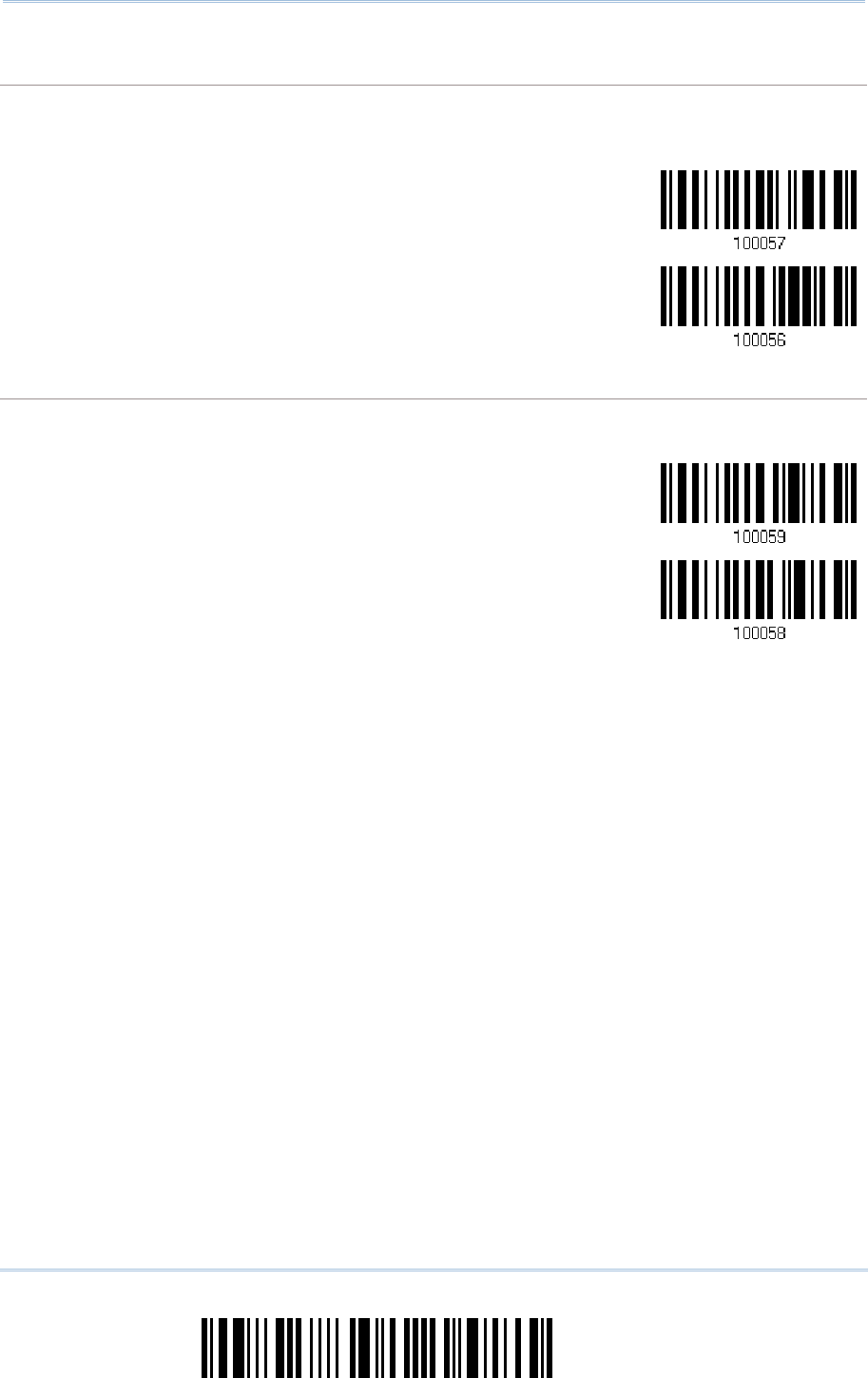
86
Enter Setup
1560/1562 Series Barcode Scanner
User Guide
ALT Composing
ALT ComposingALT Composing
ALT Composing
By default, Alternate key composing is disabled. Select [Yes] to allow emulating Alternate key code
of a specific keyboard character. For example, [Alt] + [065] will be sent to host for the character
“A” regardless the keyboard type you are using.
Yes
*No
Laptop Support
Laptop SupportLaptop Support
Laptop Support
By default, laptop support is disabled. It is suggested to enable this feature if you connect the
wedge cable to a laptop without an external keyboard being inter-connected.
Enable
*Disable
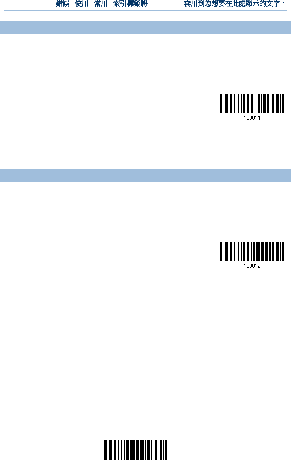
87
Update
Chapter 2
!
! !
!
[
[[
[
]
] ]
]
Heading 1
Heading 1 Heading 1
Heading 1
2.
2.2.
2.4
44
4.3 INTER
.3 INTER.3 INTER
.3 INTER-
--
-CHARACTER DELAY
CHARACTER DELAYCHARACTER DELAY
CHARACTER DELAY
By default, the inter-character delay is set to zero. Specify a value, ranging from 0 to
254 in units of millisecond, to match the computer response time of the keyboard
interface. Such delay time is inserted between every character being transmitted. The
longer the delay time is, the slower the transmission speed will be.
Inter-Character
Delay… (*0~254)
1) Read the barcode above to specify the inter-character delay.
2) Read the “Decimal Value” barcode on page 241 for the desired inter-character delay
(millisecond).
3) Read the “Validate” barcode on the same page to complete this setting.
2.
2.2.
2.4
44
4.4 INTER
.4 INTER.4 INTER
.4 INTER-
--
-FUNCTION DELAY
FUNCTION DELAYFUNCTION DELAY
FUNCTION DELAY
By default, the inter-function delay is set to zero. Specify a value, ranging from 0 to 254
in units of millisecond, to match the computer response time of the keyboard interface.
Such delay time is inserted between every function code (0x01 ~ 0x1F) being
transmitted. The longer the delay time is, the slower the transmission speed will be.
Inter-Function
Delay… (*0~254)
1) Read the barcode above to specify the inter-function delay.
2) Read the “Decimal Value” barcode on page 241 for the desired inter-function delay
(millisecond).
3) Read the “Validate” barcode on the same page to complete this setting.
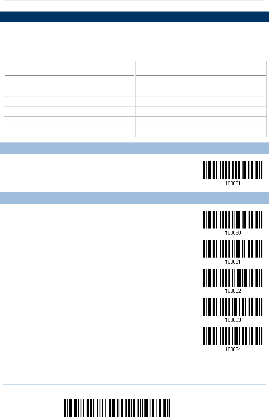
88
Enter Setup
1560/1562 Series Barcode Scanner
User Guide
2
22
2.
..
.5
55
5
RS
RSRS
RS-
--
-232
232232
232
VIA
VIA VIA
VIA 3656
36563656
3656
CRADLE
CRADLECRADLE
CRADLE
Use the RS-232 cable to connect the scanner via 3656 CRADLE to the serial port of PC,
and connect the power supply cord. The associated RS-232 parameters must match
those configured on the computer. You may run HyperTerminal.exe on your computer,
and the scanned data will be transmitted to the computer.
RS
RSRS
RS-
--
-232
232232
232
Settings
SettingsSettings
Settings
Defaults
DefaultsDefaults
Defaults
Baud Rate, Data Bit, Parity, Stop Bit 115200 bps, 8 bits, No parity, 1 stop bit
Flow Control None
Inter-Character Delay 0 (ms)
Inter-Function Delay 0 (ms)
ACK/NAK Timeout 0
ACK/NAK Beep Disable
2.
2.2.
2.5
55
5.1 ACTIVATE RS
.1 ACTIVATE RS.1 ACTIVATE RS
.1 ACTIVATE RS-
--
-232 INTERFACE
232 INTERFACE232 INTERFACE
232 INTERFACE
Activate 3656 CRADLE
RS-232 Interface
2.
2.2.
2.5
55
5.2 BAUD RATE
.2 BAUD RATE.2 BAUD RATE
.2 BAUD RATE
*115200 bps
57600 bps
38400 bps
19200 bps
9600 bps
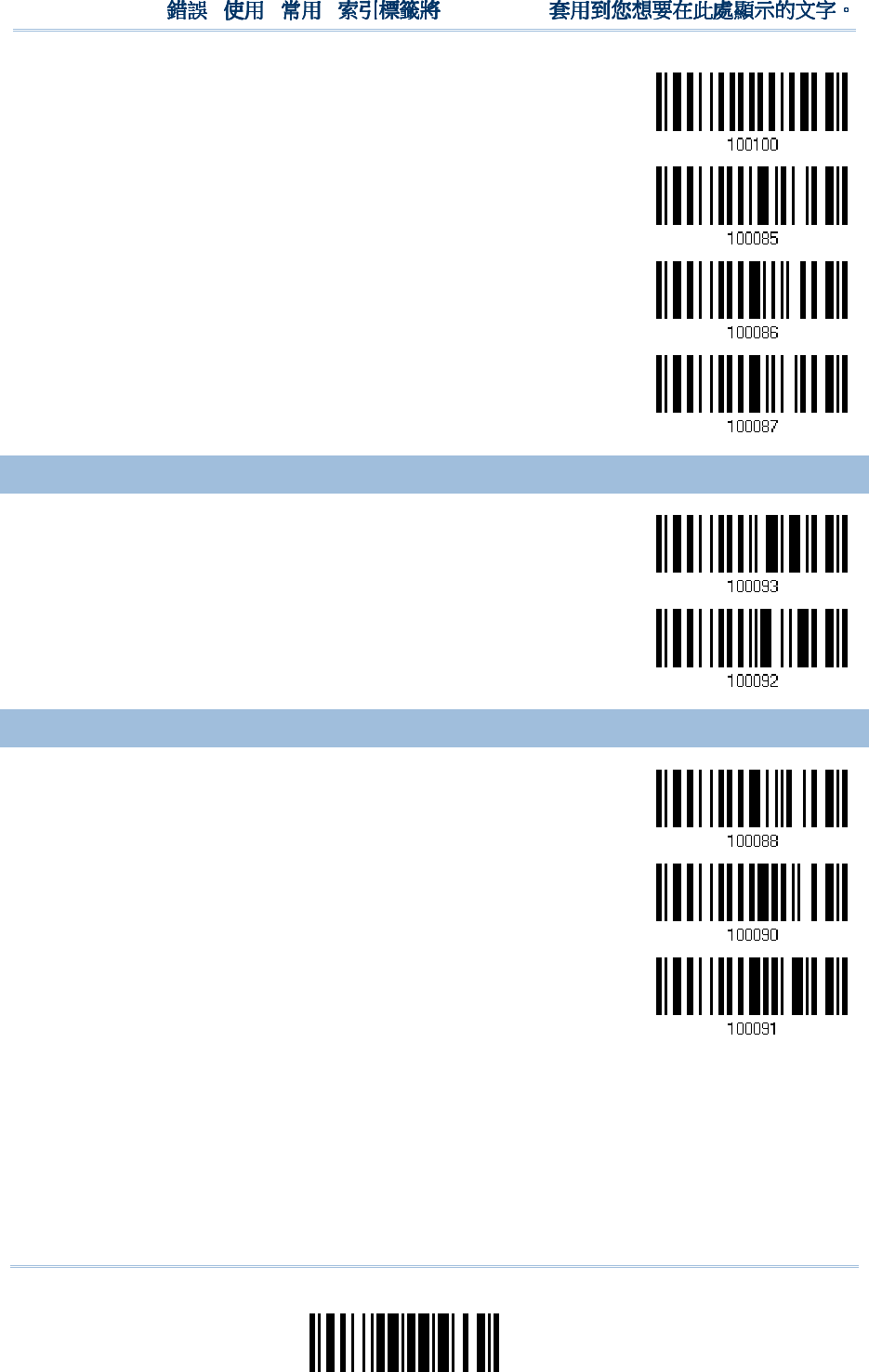
89
Update
Chapter 2
!
! !
!
[
[[
[
]
] ]
]
Heading 1
Heading 1 Heading 1
Heading 1
4800 bps
2400 bps
1200 bps
600 bps
2.
2.2.
2.5
55
5.3 DATA BITS
.3 DATA BITS.3 DATA BITS
.3 DATA BITS
*8 bits
7 bits
2.
2.2.
2.5
55
5.4 PARITY
.4 PARITY.4 PARITY
.4 PARITY
*No parity
Even
Odd
90
Enter Setup
1560/1562 Series Barcode Scanner
User Guide
2.
2.2.
2.5
55
5.5 STOP BIT
.5 STOP BIT.5 STOP BIT
.5 STOP BIT
2 stop bits
*1 stop bit
2.
2.2.
2.5
55
5.6 FLOW CONTROL
.6 FLOW CONTROL.6 FLOW CONTROL
.6 FLOW CONTROL
By default, there is no flow control in use. Select the flow control (handshake) method.
Options
OptionsOptions
Options
Description
DescriptionDescription
Description
No No flow control
Scanner Ready The scanner will activate the RTS signal upon powering on. After each good
read, the scanner will then wait for the CTS signal to become active. Data
will not be sent until the CTS signal becomes active.
Data Ready The RTS signal will be activated after each good read. The scanner will then
wait for the CTS signal to become active. Data will not be sent until the CTS
signal becomes active.
Inverted Data Ready
It works the same as the Data Ready flow control except that the RTS signal
level is inverted.
*None
Scanner Ready
Data Ready
Invert Data
Ready
91
Update
Chapter 2
!
! !
!
[
[[
[
]
] ]
]
Heading 1
Heading 1 Heading 1
Heading 1
2.
2.2.
2.5
55
5.7 INTER
.7 INTER.7 INTER
.7 INTER-
--
-CHARACTER DELAY
CHARACTER DELAYCHARACTER DELAY
CHARACTER DELAY
By default, the inter-character delay is zero. Specify a value, ranging from 0 to 254 in
units of millisecond, to match the computer response time. Such delay time is inserted
between every character being transmitted. The longer the delay time is, the slower the
transmission speed will be.
Inter-Character
Delay… (*0~254)
1) Read the barcode above to specify the inter-character delay.
2) Read the “Decimal Value” barcode on page 241 for the desired inter-character delay
(millisecond).
3) Read the “Validate” barcode on the same page to complete this setting.
2.
2.2.
2.5
55
5.8 INTER
.8 INTER.8 INTER
.8 INTER-
--
-FUNCTION DELAY
FUNCTION DELAYFUNCTION DELAY
FUNCTION DELAY
By default, the inter-function delay is set to zero. Specify a value, ranging from 0 to 254
in units of millisecond, to match the computer response time of the keyboard interface.
Such delay time is inserted between every function code (0x01 ~ 0x1F) being
transmitted. The longer the delay time is, the slower the transmission speed will be.
Inter-Function
Delay… (*0~254)
1) Read this barcode above to specify the inter-function delay.
2) Read the “Decimal Value” barcode on page 241 for the desired inter-function delay
(millisecond).
3) Read the “Validate” barcode on the same page to complete this setting.
92
Enter Setup
1560/1562 Series Barcode Scanner
User Guide
2.
2.2.
2.5
55
5.9
.9 .9
.9 ACK/NAK TIMEOUT
ACK/NAK TIMEOUTACK/NAK TIMEOUT
ACK/NAK TIMEOUT
By default, the scanner sends data to the host without waiting for an ACK/NAK response
before sending more data. Specify a value, ranging from 1 to 99 in units of 0.1 second. If
no response within the specified period of time, the scanner will attempt to send the
same data two more times. If all three attempts fail without any notification, data loss
will occur.
ACK/NAK
Time-out after …
(*0~99)
1) Read the barcode above to specify the time interval for the scanner to send data and
wait for a response from the host.
2) Read the “Decimal Value” barcode on page 241. For example, read “1” and “0” for the
scanner to automatically shut down after idleness off 1 second.
3) Read the “Validate” barcode on the same page to complete this setting.
ACK/NAK Error Beep
ACK/NAK Error BeepACK/NAK Error Beep
ACK/NAK Error Beep
Enable Error Beep
*Disable Error
Beep
Note: We suggest enabling the error beep so that you will be notified of such data loss
and have the scanner re-read data.
93
Update
Chapter 2
!
! !
!
[
[[
[
]
] ]
]
Heading 1
Heading 1 Heading 1
Heading 1
2.
2.2.
2.6
66
6
USB HID VIA
USB HID VIA USB HID VIA
USB HID VIA 3656
36563656
3656
CRADLE
CRADLECRADLE
CRADLE
For USB HID, use the USB cable to connect the scanner via 3656 CRADLE to the USB
port of PC and connect the power supply cord. Run any text editor on your computer,
and the scanned data will be transmitted to the computer.
Warning: When the 3656 CRADLE stand is solely on USB power, the current may be
insufficient for it to function normally. You must connect the power supply
cord.
HID Settings
HID SettingsHID Settings
HID Settings
Defaults
DefaultsDefaults
Defaults
Keyboard Type PCAT (US)
Digits Layout Normal
Capital Lock Type Normal
Capital Lock State Off
Alphabets Transmission Case-sensitive
Digits Transmission Alphanumeric keypad
Inter-Character Delay 0 (ms)
Inter-Function Delay 0 (ms)
94
Enter Setup
1560/1562 Series Barcode Scanner
User Guide
2.
2.2.
2.6
66
6.1 ACTIVATE
.1 ACTIVATE .1 ACTIVATE
.1 ACTIVATE USB
USB USB
USB HID & SELECT KE
HID & SELECT KEHID & SELECT KE
HID & SELECT KEYBOARD TYPE
YBOARD TYPEYBOARD TYPE
YBOARD TYPE
When USB HID interface is activated, you will have to select a keyboard type to complete
this setting.
Activate
3656 CRADLE USB HID &
Select Keyboard
Type…
1) Read the barcode above to activate USB HID and select a keyboard type.
2) Read the “Decimal Value” barcode on page 241. Refer to the table below for the
number of desired keyboard type.
3) Read the “Validate” barcode on the same page to complete this setting.
USB HID
USB HIDUSB HID
USB HID
By default, the keyboard type is set to PCAT (US). The following keyboard types are supported —
No.
No.No.
No.
Keyboard Type
Keyboard TypeKeyboard Type
Keyboard Type
No.
No.No.
No.
Keyboard Type
Keyboard TypeKeyboard Type
Keyboard Type
64 PCAT (US) 72 PCAT (Spanish)
65 PCAT (French) 73 PCAT (Portuguese)
66 PCAT (German) 74 PS55 A01-2 (Japanese)
67 PCAT (Italy) 75 User-defined table
68 PCAT (Swedish) 76 PCAT (Turkish)
69 PCAT (Norwegian) 77 PCAT (Hungarian)
70 PCAT (UK) 78 PCAT (Swiss German)
71 PCAT (Belgium) 79 PCAT (Danish)
95
Update
Chapter 2
!
! !
!
[
[[
[
]
] ]
]
Heading 1
Heading 1 Heading 1
Heading 1
2.
2.2.
2.6
66
6.
..
.2
22
2
KEYBOARD SETTINGS
KEYBOARD SETTINGSKEYBOARD SETTINGS
KEYBOARD SETTINGS
Alphabets Layout
Digits Layout
Capital Lock Type
Capital Lock Setting
Alphabets Transmission
Digits Transmission
Alphabets Layout
Alphabets LayoutAlphabets Layout
Alphabets Layout
By default, the alphabets layout is set to normal mode, also known as the standard English layout.
Select French or German keyboard layout if necessary. The scanner will make adjustments when
sending the "A", "Q", "W", "Z", "Y", and "M" characters according to this setting.
*Normal
AZERTY
QWERTZ
Note: This setting only works when the keyboard type selected is US keyboard, such as
PCAT (US). The Alphabets Layout and Digits Layout setting must match your
keyboard.
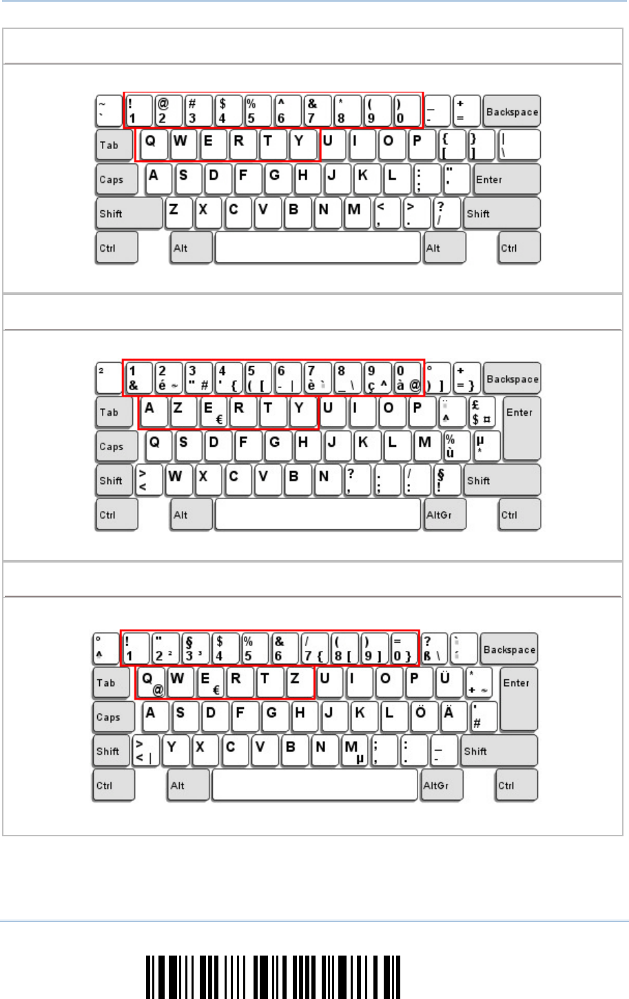
96
Enter Setup
1560/1562 Series Barcode Scanner
User Guide
US Keyboard Style
US Keyboard Style US Keyboard Style
US Keyboard Style –
––
–
Normal
NormalNormal
Normal
QWERTY layout, which is normally used in western countries.
Select “Lower Row” for the “Digits Layout” setting for the upper row is for special characters.
French Keyboard Style
French Keyboard Style French Keyboard Style
French Keyboard Style –
––
–
AZERTY
AZERTYAZERTY
AZERTY
French layout; see below for French Keyboard Style.
Select “Upper Row” for the “Digits Layout” setting for the lower row is for special characters.
German Keyboard Layout
German Keyboard Layout German Keyboard Layout
German Keyboard Layout –
––
–
Q
QQ
QWERTZ
WERTZWERTZ
WERTZ
German layout; see below for German Keyboard Style.
Select “Lower Row” for the “Digits Layout” setting for the upper row is for special characters.
97
Update
Chapter 2
!
! !
!
[
[[
[
]
] ]
]
Heading 1
Heading 1 Heading 1
Heading 1
Digits Layout
Digits LayoutDigits Layout
Digits Layout
Select a proper layout that matches the alphabets layout. The scanner will make adjustments
according to this setting.
Options
OptionsOptions
Options
Description
DescriptionDescription
Description
Normal Depends on the [Shift] key or [Shift Lock] setting
Lower Row For QWERTY or QWERTZ keyboard
Upper Row For AZERTY keyboard
*Normal
Upper Row
Lower Row
Note: This setting is to be used with the Character Substitution setting when support to
certain keyboard types (languages) is unavailable but required.
98
Enter Setup
1560/1562 Series Barcode Scanner
User Guide
Capital Lock Type & Setting
Capital Lock Type & SettingCapital Lock Type & Setting
Capital Lock Type & Setting
In order to send the alphabets with correct case, the scanner needs to know the status of Caps
Lock on the keyboard. Incorrect settings may result in reversed case of the alphabets being
transmitted.
Cap Lock Type
Cap Lock TypeCap Lock Type
Cap Lock Type
Description
DescriptionDescription
Description
Normal Normal type
Capital Lock When enabled, the keys of alphabetic characters will be inter
preted as
capital letters. However, this does not affect the number or punctuation
keys.
Shift Lock
When enabled, the keys of alphabetic characters will be interpreted as
capital letters. In addition, this affects the number or punctuation keys.
*Normal
Shift Lock
Capital Lock
Capital Lock State
Capital Lock StateCapital Lock State
Capital Lock State
Description
DescriptionDescription
Description
Capital Lock OFF
Assuming that the status of Caps Lock on the keyboard is OFF,
transmitted characters are exactly the same as in the barcode (when
"case-sensitive" is selected for Alphabets Transmission).
Capital Lock ON
Assuming that the status of Caps Lock on the keyboard is ON, transmitted
characters are exactly the same as in the barcode (when "case-
sensitive"
is selected for Alphabets Transmission).
Refer to the Capital Lock Type above.
Auto Detection
The scanner will automatically detect the status of Caps Lock on the
keyboard before data is transmitted; transmitted characters are exactly
the same as in the barcode (when "case-
sensitive" is selected for
Alphabets Transmission).
Auto Detect
Capital Lock ON

99
Update
Chapter 2
!
! !
!
[
[[
[
]
] ]
]
Heading 1
Heading 1 Heading 1
Heading 1
*Capital Lock OFF
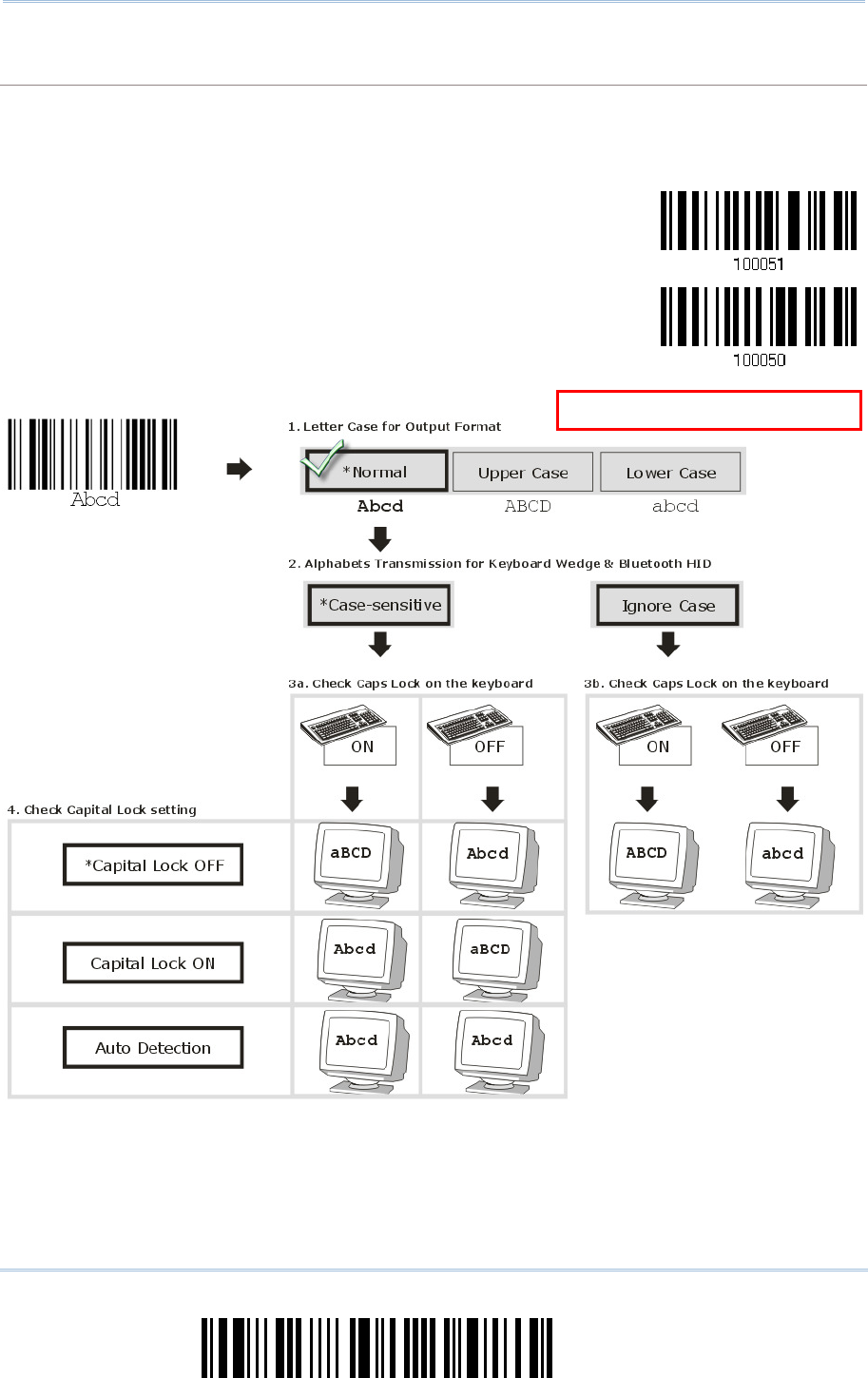
100
Enter Setup
1560/1562 Series Barcode Scanner
User Guide
Alphabets Transmission
Alphabets TransmissionAlphabets Transmission
Alphabets Transmission
By default, the alphabets transmission is case-sensitive, meaning that the alphabets will be
transmitted according to their original case, the status of Caps Lock on the keyboard, as well as the
Capital Lock setting. Select [Ignore Case] to have alphabets transmitted according to the status of
Caps Lock on the keyboard only.
Ignore Case
*Case-sensitive
Refer to 5.1 Letter Case.
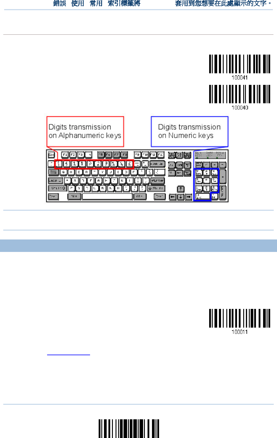
101
Update
Chapter 2
!
! !
!
[
[[
[
]
] ]
]
Heading 1
Heading 1 Heading 1
Heading 1
Digits Transmiss
Digits TransmissDigits Transmiss
Digits Transmission
ionion
ion
By default, the alphanumeric keypad is used for transmitting digits. Select “Numeric Keypad” if you
wish to use the keys on the numeric keypad.
Numeric Key
*Alphanumeric Key
Note: If you select “Numeric Keypad”, the Num Lock status of the physical keyboard
should be "ON".
2.6.3 INTER
2.6.3 INTER2.6.3 INTER
2.6.3 INTER-
--
-CHARACTER DELAY
CHARACTER DELAYCHARACTER DELAY
CHARACTER DELAY
By default, the inter-character delay is set to zero. Specify a value, ranging from 0 to
254 in units of millisecond, to match the computer response time of the keyboard
interface. Such delay time is inserted between every character being transmitted. The
longer the delay time is, the slower the transmission speed will be.
Inter-Character
Delay… (*0~254)
1) Read the barcode above to specify the inter-character delay.
2) Read the “Decimal Value” barcode on page 241 for the desired inter-character delay
(millisecond).
3) Read the “Validate” barcode on the same page to complete this setting.
102
Enter Setup
1560/1562 Series Barcode Scanner
User Guide
2.
2.2.
2.6
66
6.
..
.4
44
4
INTER
INTERINTER
INTER-
--
-FUNCTION DELA
FUNCTION DELAFUNCTION DELA
FUNCTION DELAY
YY
Y
By default, the inter-function delay is set to zero. Specify a value, ranging from 0 to 254
in units of millisecond, to match the computer response time of the keyboard interface.
Such delay time is inserted between every function code (0x01 ~ 0x1F) being
transmitted. The longer the delay time is, the slower the transmission speed will be.
Inter-Function
Delay… (*0~254)
1) Read the barcode above to specify the inter-function delay.
2) Read the “Decimal Value” barcode on page 241 for the desired inter-function delay
(millisecond).
3) Read the “Validate” barcode on the same page to complete this setting.
2.
2.2.
2.6
66
6.
..
.5
55
5
HID CHARACTER TRANSM
HID CHARACTER TRANSMHID CHARACTER TRANSM
HID CHARACTER TRANSMIT MODE
IT MODEIT MODE
IT MODE
B By default, HID interface sends data to the host character by character. You may have
the scanner read the “Batch Processing” barcode to process data in batch.
Batch Processing
*By Character
103
Update
Chapter 2
!
! !
!
[
[[
[
]
] ]
]
Heading 1
Heading 1 Heading 1
Heading 1
2.
2.2.
2.7
77
7
USB VIRTUAL COM VIA
USB VIRTUAL COM VIA USB VIRTUAL COM VIA
USB VIRTUAL COM VIA 3656
36563656
3656
CRADLE
CRADLECRADLE
CRADLE
Use the USB cable to connect the scanner via 3656 CRADLE to the USB port of PC and
connect the power supply cord. You may run HyperTerminal.exe on your computer, and
the scanned data will be transmitted to the computer.
Warning: When the 3656 CRADLE stand is solely on USB power, the current may be
insufficient for it to function normally. You must connect the power supply
cord.
Note: If using USB Virtual COM for the first time, you must install its driver beforehand.
Driver version 5.4 or later is required. Please remove older versions!
2.
2.2.
2.7
77
7.1 ACTIVATE
.1 ACTIVATE .1 ACTIVATE
.1 ACTIVATE USB VIRTUAL COM
USB VIRTUAL COMUSB VIRTUAL COM
USB VIRTUAL COM
Activate 3656 CRADLE
USB Virtual COM
2.
2.2.
2.7
77
7.2 INTER
.2 INTER.2 INTER
.2 INTER-
--
-FUNCTION DELAY
FUNCTION DELAYFUNCTION DELAY
FUNCTION DELAY
By default, the inter-function delay is set to zero. Specify a value, ranging from 0 to 254
in units of millisecond, to match the computer response time of the keyboard interface.
Such delay time is inserted between every function code (0x01 ~ 0x1F) being
transmitted. The longer the delay time is, the slower the transmission speed will be.
Inter-Function
Delay… (*0~254)
1) Read the barcode above to specify the inter-function delay.
2) Read the “Decimal Value” barcode on page 241 for the desired inter-function delay
(millisecond).
3) Read the “Validate” barcode on the same page to complete this setting.
104
Enter Setup
1560/1562 Series Barcode Scanner
User Guide
2.
2.2.
2.7
77
7.3 ACK/NAK TIMEOUT
.3 ACK/NAK TIMEOUT.3 ACK/NAK TIMEOUT
.3 ACK/NAK TIMEOUT
By default, the scanner sends data to the host without waiting for an ACK/NAK response
before sending more data. Specify a value, ranging from 1 to 99 in units of 0.1 second. If
no response within the specified period of time, the scanner will attempt to send the
same data two more times. If all three attempts fail without any notification, data loss
will occur.
ACK/NAK Time-out
after … (*0~99)
1) Read the barcode above to specify the time interval for the scanner to send data and
wait for a response from the host.
2) Read the “Decimal Value” barcode on page 241. For example, read “1” and “0” for the
scanner to automatically shut down after being idle for 1 second.
3) Read the “Validate” barcode on the same page to complete this setting.
ACK/NAK Error Beep
ACK/NAK Error BeepACK/NAK Error Beep
ACK/NAK Error Beep
Enable Error Beep
*Disable Error Beep
Note: We suggest enabling the error beep so that you will be notified of such data loss
and have the scanner re-read data.
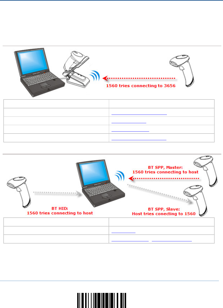
105
Update
The 1560/1562 scanner can be configured to send data to a host computer wirelessly via
the 3656 CRADLE stand, or to a notebook computer or PDA with Bluetooth
®
wireless
technology. Upon powering up, the scanner will be ready for establishing a WPAN
connection.
To establish a connection via
To establish a connection via To establish a connection via
To establish a connection via 3656
36563656
3656
CRADLE
CRADLECRADLE
CRADLE
after reading “Set Connection” and “Serial No.” labels …
after reading “Set Connection” and “Serial No.” labels …after reading “Set Connection” and “Serial No.” labels …
after reading “Set Connection” and “Serial No.” labels …
Interface Option Reference
Keyboard Wedge 2.4 Keyboard Wedge via
RS-232 2.5 RS-232 via
USB HID 2.6 USB HID via
USB Virtual COM 2.7 USB Virtual COM via
To estab
To estabTo estab
To establish a connection via
lish a connection via lish a connection via
lish a connection via Bluetooth
BluetoothBluetooth
Bluetooth
®
®®
®
dongle
dongle dongle
dongle after pairing
after pairingafter pairing
after pairing…
……
…
Interface Option Reference
BT HID 2.1 BT HID
BT SPP 2.2 BT SPP Slave, 2.3 BT SPP Master
Chapter
Chapter Chapter
Chapter
3
33
3
SETTING UP
SETTING UP SETTING UP
SETTING UP A WPAN CONNECTION
A WPAN CONNECTIONA WPAN CONNECTION
A WPAN CONNECTION

106
Enter Setup
1560/1562 Series Barcode Scanner
User Guide
IN THIS CHAPTER
IN THIS CHAPTERIN THIS CHAPTER
IN THIS CHAPTER
3.1 Connecting via ........................................................ 107
3.2 Connecting via Bluetooth
®
Dongle ............................... 111
107
Update
Chapter 3
!
! !
!
[
[[
[
]
] ]
]
Heading 1
Heading 1 Heading 1
Heading 1
3.
3.3.
3.1
11
1
CONNECTING VIA
CONNECTING VIA CONNECTING VIA
CONNECTING VIA 3656
36563656
3656
CRADLE
CRADLECRADLE
CRADLE
By default, the interface of 3656 CRADLE is set to “USB HID”. Use the interface cable to
connect the scanner via 3656 CRADLE to PC. You can have up to seven scanners
connected to one computer at the same time.
Note: If using USB Virtual COM for the first time, you must install its driver beforehand.
Driver version 5.4 or later is required. Please remove older versions!
3.
3.3.
3.1
11
1.1 CONNECT TO
.1 CONNECT TO .1 CONNECT TO
.1 CONNECT TO 3656
36563656
3656
CRADLE
CRADLECRADLE
CRADLE
By scanning two setting barcodes in sequence
By scanning two setting barcodes in sequenceBy scanning two setting barcodes in sequence
By scanning two setting barcodes in sequence
Connect any scanner to 3656 CRADLE by reading the two labels at the back of 3656 CRADLE. The
scanner will respond with one beep upon reading each of the labels.
“Set Connection” label
“Serial Number” label
After reading these labels, the scanner will stay active for a specified period of time (2 minutes by
default) trying to connect to the 3656 CRADLE while its LED is flashing blue (On/Off ratio 0.5 s: 0.5
s). Once connected, the scanner will respond with three beeps (tone ascending from low to high),
and the LED flashes blue (On/Off ratio 0.02 s: 3 s). When out of range, the scanner will respond
with three short beeps (tone descending from high to low).
Usage:
Read the “Set Connection” barcode first, and then the “Serial Number” barcode. If the “Set
Connection” barcode on 3656 CRADLE is illegible, try this one —
Set Connection
Note: The 3656 CRADLE settings will overwrite the interface-related settings on the
scanners that are currently connected to 3656 CRADLE.
By scanning a single 1D setting barcode
By scanning a single 1D setting barcodeBy scanning a single 1D setting barcode
By scanning a single 1D setting barcode
Users can produce a single 1D setup barcode that combines the “Set Connection” and “3656
CRADLE Serial Number” setup commands to connect with the target device. While producing the
barcode, be aware the letter upper/lower case “SeTcOn” and the barcode must be the Code 128
symbology.
Usage:
Read the “SeTcOnxxxxxxxxx” single 1D barcode. The scanner will respond with one beep
upon reading the barcode.

108
Enter Setup
1560/1562 Series Barcode Scanner
User Guide
3.
3.3.
3.1
11
1.
..
.2
22
2
CHANGE
CHANGECHANGE
CHANGE
INTERFACE
INTERFACEINTERFACE
INTERFACE
If you want to change the interface cable of 3656 CRADLE, use one of the scanners to
configure the interface-related settings and it will pass the new settings to 3656 CRADLE,
which will then initialize and pass the settings to any other connected scanners.
1) Have the scanner read the “Set Connection” and “Serial Number” labels at the back of
3656 CRADLE.
2) Within two minutes, connect the interface cable between 3656 CRADLE and your
computer. For USB Virtual COM, you may need to install its driver first!
3) The scanners will connect to your computer via 3656 CRADLE.
4) Have one scanner read the “Enter Setup” barcode to enter the configuration mode.
5) Have the scanner read the desired interface barcode and configure its related
settings –
“Activate Keyboard Wedge & Select Keyboard Type”
“Activate RS-232”
“Activate USB HID & Select Keyboard Type”
“Activate USB Virtual COM”
6) Have the scanner read the “Update” barcode to exit the configuration mode.
7) After the scanner resumes connection with 3656 CRADLE, it will pass the
interface-related settings to 3656 CRADLE.
8) Upon receipt of the new settings, 3656 CRADLE will initialize itself.
9) Updated with new settings, 3656 CRADLE will pass the settings to other connected
scanners.
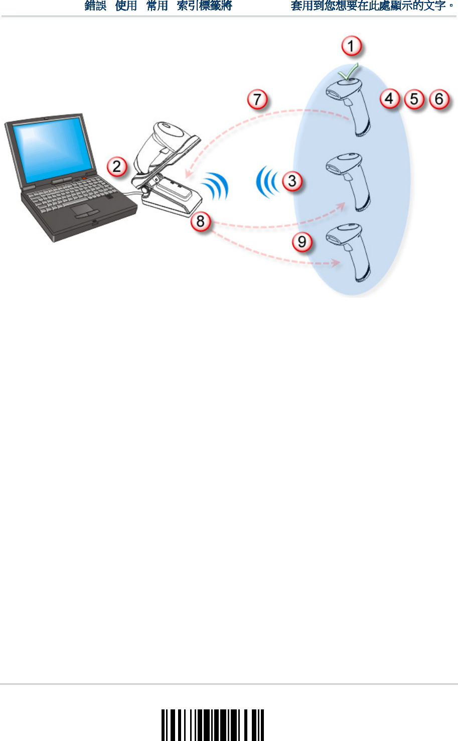
109
Update
Chapter 3
!
! !
!
[
[[
[
]
] ]
]
Heading 1
Heading 1 Heading 1
Heading 1

110
Enter Setup
1560/1562 Series Barcode Scanner
User Guide
3.
3.3.
3.1.3
1.31.3
1.3
CONFIGUR
CONFIGURCONFIGUR
CONFIGURE RELATED
E RELATEDE RELATED
E RELATED
SETTINGS
SETTINGSSETTINGS
SETTINGS
Sniff Mode (Power
Sniff Mode (PowerSniff Mode (Power
Sniff Mode (Power-
--
-saving)
saving)saving)
saving)
By default, this feature is enabled, meaning the scanner will listen to the wireless network at a
reduced rate.
*Enable
Disable

111
Update
Chapter 3
!
! !
!
[
[[
[
]
] ]
]
Heading 1
Heading 1 Heading 1
Heading 1
3.
3.3.
3.2
22
2
CONNECTING VIA
CONNECTING VIA CONNECTING VIA
CONNECTING VIA BLUETOOTH
BLUETOOTHBLUETOOTH
BLUETOOTH
®
®®
®
DONGLE
DONGLEDONGLE
DONGLE
3.
3.3.
3.2
22
2.1 C
.1 C.1 C
.1 CHANGE
HANGEHANGE
HANGE
INTERFACE
INTERFACEINTERFACE
INTERFACE
Below is the procedure to configure the scanner before establishing a WPAN connection
via Bluetooth
®
dongle.
1) Have the scanner read the “Enter Setup” barcode to enter the configuration mode.
2) Have the scanner read the desired interface barcode –
“Activate BT HID & Select Keyboard Type”
“Activate BT SPP Slave Mode”
“Activate BT SPP Master Mode”
3) Have the scanner read the barcodes related to WPAN settings, such as Device Name
Broadcasting, Authentication & PIN Code, etc.
4) Have the scanner read the “Update” barcode to exit the configuration mode.
5) The scanner will stay active for a specified period of time (2 minutes by default)
waiting for a connection request from the host (SPP Slave Mode) or trying to connect
to the host (HID or SPP Master Mode). Its CPU is running at full speed, and the LED is
flashing blue (On/Off ratio 0.5 s: 0.5 s).
Once connected, when getting out of range, the scanner will respond with three short
beeps (tone descending from high to low).
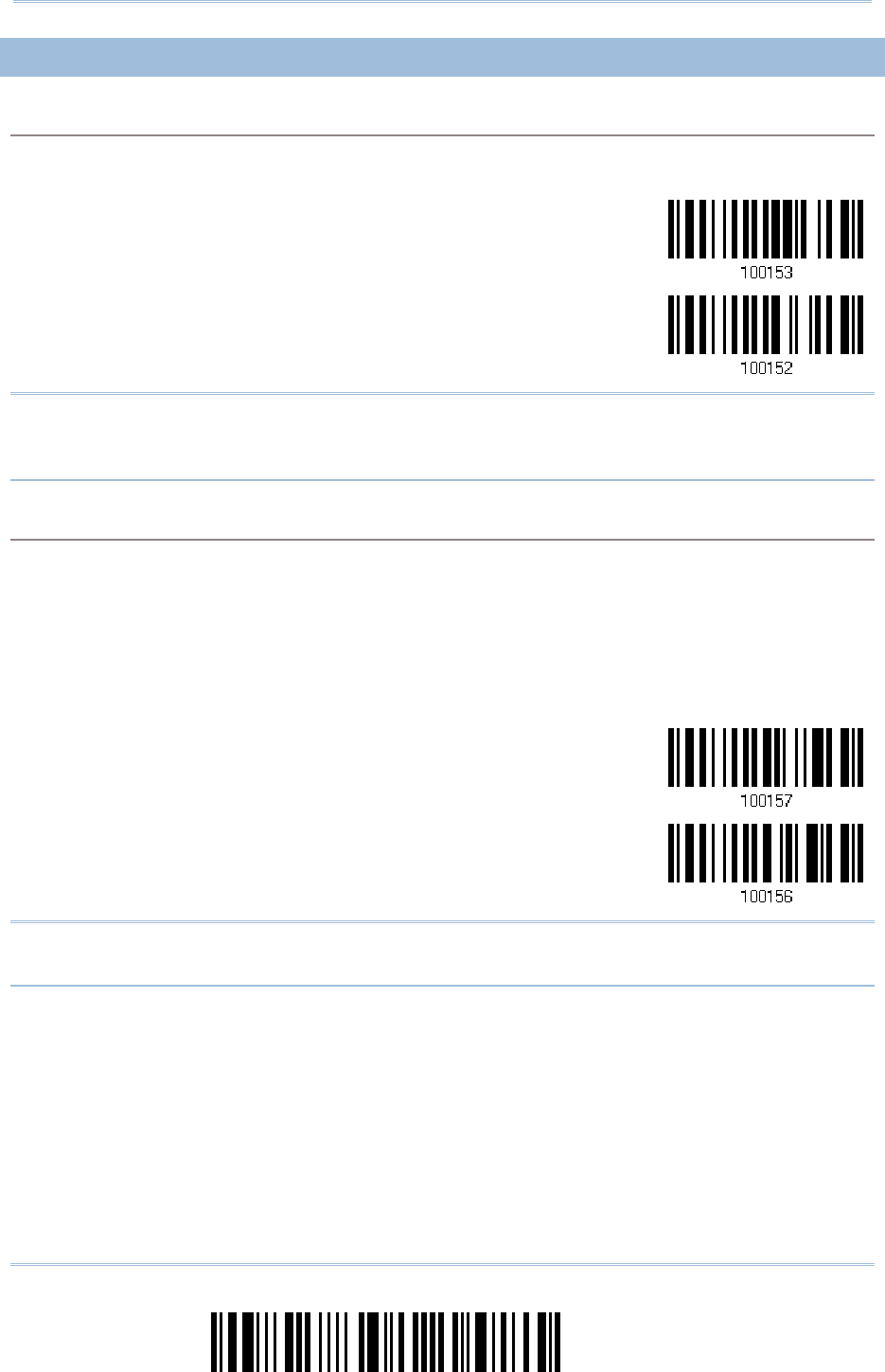
112
Enter Setup
1560/1562 Series Barcode Scanner
User Guide
3
33
3.
..
.2
22
2.
..
.2
22
2
CONFIGUR
CONFIGURCONFIGUR
CONFIGURE RELATED
E RELATEDE RELATED
E RELATED
SETTINGS
SETTINGSSETTINGS
SETTINGS
Sniff Mode (Power
Sniff Mode (PowerSniff Mode (Power
Sniff Mode (Power-
--
-saving)
saving)saving)
saving)
By default, this feature is enabled, meaning the scanner will listen to the wireless network at a
reduced rate.
*Enable
Disable
Note: When connecting more than two scanners to a notebook computer or PDA with
Bluetooth
®
wireless technology, we suggest that you disable the power-saving
setting for a more reliable connection.
Device Name Broadcasting
Device Name BroadcastingDevice Name Broadcasting
Device Name Broadcasting
The scanner can be configured to hide itself from other devices equipped with Bluetooth
®
wireless
technology. Simply disable the device name broadcasting setting so that it won’t be discovered by
any other computer or PDA. However, broadcasting must be enabled for establishing an initial
connection with the scanner. For example, you can disable device name broadcasting after
successfully connecting the scanner to WorkStation1. Such connection will be maintained
automatically unless the scanner is removed from the paired device list (called unpairing) by
WorkStation1 or any changes made to authentication and the PIN code. If you want WorkStation2
to connect to the scanner, you will have to enable device name broadcasting first.
*Enable
Disable
Note: By default, device name broadcasting is enabled (which is required for initial
connection).
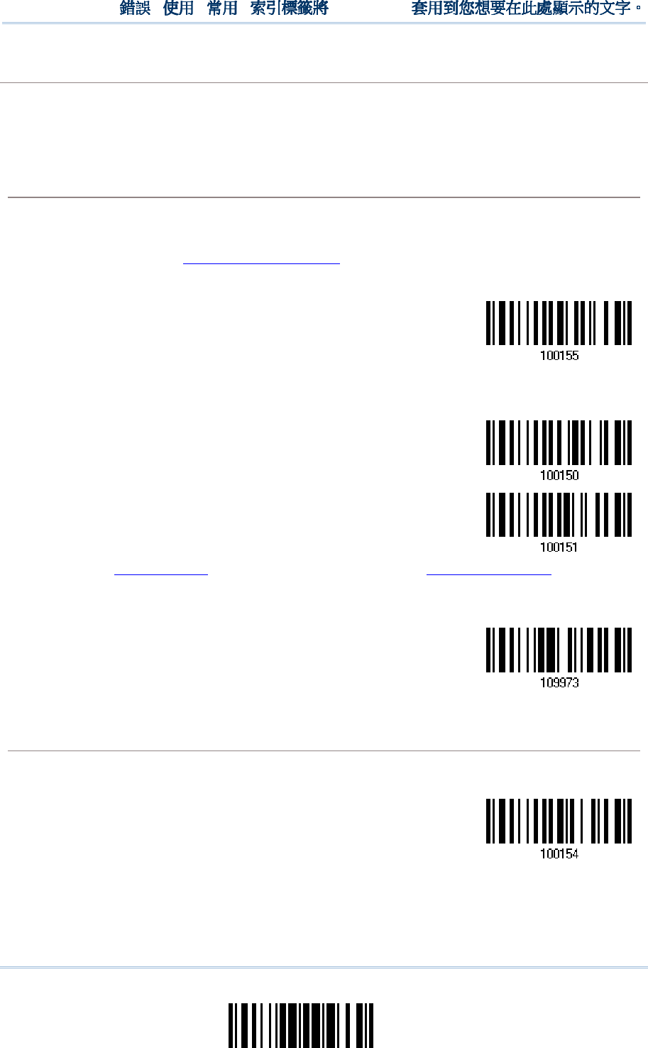
113
Update
Chapter 3
!
! !
!
[
[[
[
]
] ]
]
Heading 1
Heading 1 Heading 1
Heading 1
Authentication
AuthenticationAuthentication
Authentication
When any changes are made to authentication and PIN code on the scanner side, you will have to
remove the scanner from the paired device list (called unpairing) and go through the whole process
to re-establish the connection.
The scanner allows up to 16 characters for a PIN code and provides two options for authentication:
Enable
Enable Enable
Enable Authentication
AuthenticationAuthentication
Authentication
with Preset PIN
with Preset PINwith Preset PIN
with Preset PIN
Have the scanner read the “Use preset PIN” barcode, and change the preset PIN if necessary.
This means you will have to enter exactly the same string for your computer or PDA to connect
to the scanner. If the PIN or passkey is incorrect, any connection attempt will be turned down by
the scanner. See step 8 in 3.2.3 Connect to Dongle.
1.
Read the “Use preset PIN” barcode to enable authentication with a preset PIN.
Use Preset PIN
2.
Read one of the barcodes to specify the PIN code, in decimal or hexadecimal.
By default, the PIN code is set to “0000”. Maximum 16 characters are allowed.
Enter PIN in
Hexadecimal …
Enter PIN in
Decimal…
3.
Read the “Decimal Value” barcode on page 241 or the “Hexadecimal Value” barcode on
page 242 for the desired digits or character string.
Read the “Clear PIN Code” barcode first if you need to re-input the PIN code.
Clear PIN Code
4.
Read the “Validate” barcode to complete this setting.
Enable
Enable Enable
Enable Authentication
AuthenticationAuthentication
Authentication
with Random PIN or No Authentication
with Random PIN or No Authenticationwith Random PIN or No Authentication
with Random PIN or No Authentication
By default, it is set to “No PIN or use random PIN”, which depends on the setting of the target
device. (No PIN = No authentication.)
*No PIN or
use random PIN
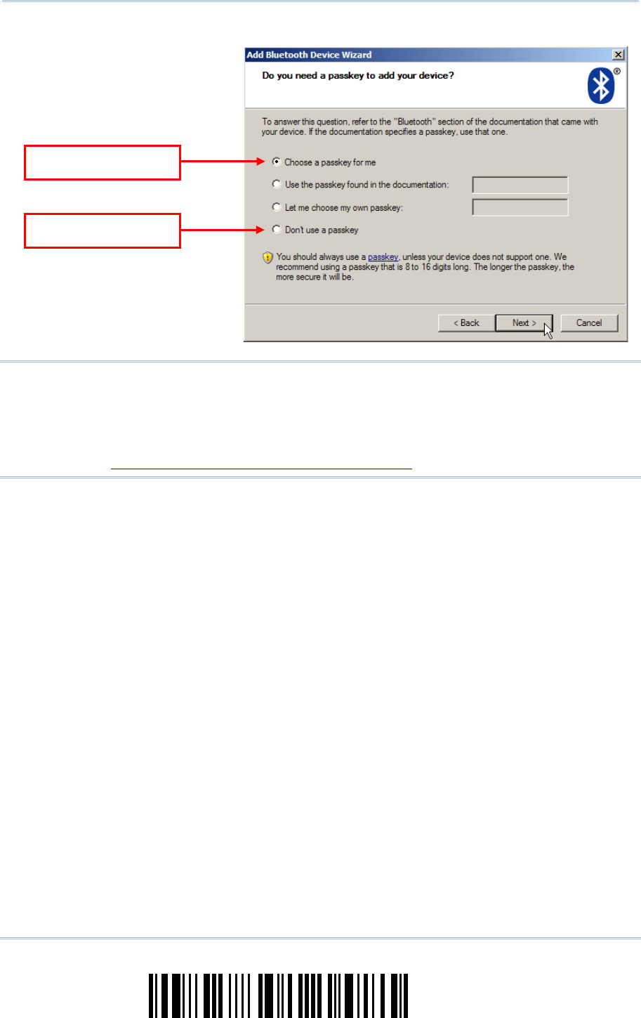
114
Enter Setup
1560/1562 Series Barcode Scanner
User Guide
Note: When using BT HID, some device driver may not support pre-defined PIN code for
authentication. In this case, make sure you have the scanner set to “No PIN or use
random PIN” before pairing. While pairing, the host PIN code will be displayed on
the computer screen. Have the scanner read the setup barcode “Enter PIN Code in
Decimal” or “Enter PIN Code in Hexadecimal” to input the matching PIN code.
Refer to Disable Authentication or Use Random PIN.
Use random PIN
No PIN required
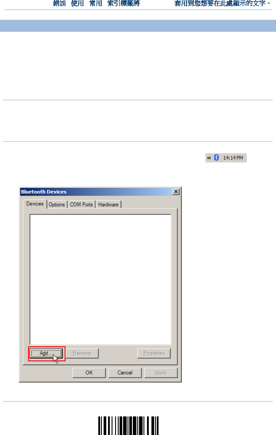
115
Update
Chapter 3
!
! !
!
[
[[
[
]
] ]
]
Heading 1
Heading 1 Heading 1
Heading 1
3.2.
3.2.3.2.
3.2.3
33
3
CONNECT TO DONGLE
CONNECT TO DONGLECONNECT TO DONGLE
CONNECT TO DONGLE
The procedure goes through associating devices for establishing a WPAN connection,
which is pretty much the same except for the software you are using. If your computer is
running Microsoft
®
Windows
®
XP Service Pack 3 (SP3) or Windows Vista
®
Service Pack 1
(SP1), you can use the software support that Windows
®
includes, or you can use the
driver that the device manufacturer provides. Now, let’s try using the software support
that Windows
®
XP Service Pack 2 includes.
BT HID Procedure
BT HID ProcedureBT HID Procedure
BT HID Procedure
By default, BT HID is activated on the scanner, and the keyboard type is set to PCAT (US). When
BT HID is re-activated, you will have to select a keyboard type to complete this setting.
The procedure is the same as for BT SPP. Refer to steps 1~11 below.
BT
BT BT
BT SPP
SPPSPP
SPP
Procedure
ProcedureProcedure
Procedure
1. Turn on the Bluetooth
®
function on your computer, running Windows XP SP2.
2. Double-click the Bluetooth
®
icon from the lower right of the taskbar.
Alternatively, you may go to Control Panel > Bluetooth Devices.
3. Click [Add] to search devices nearby.
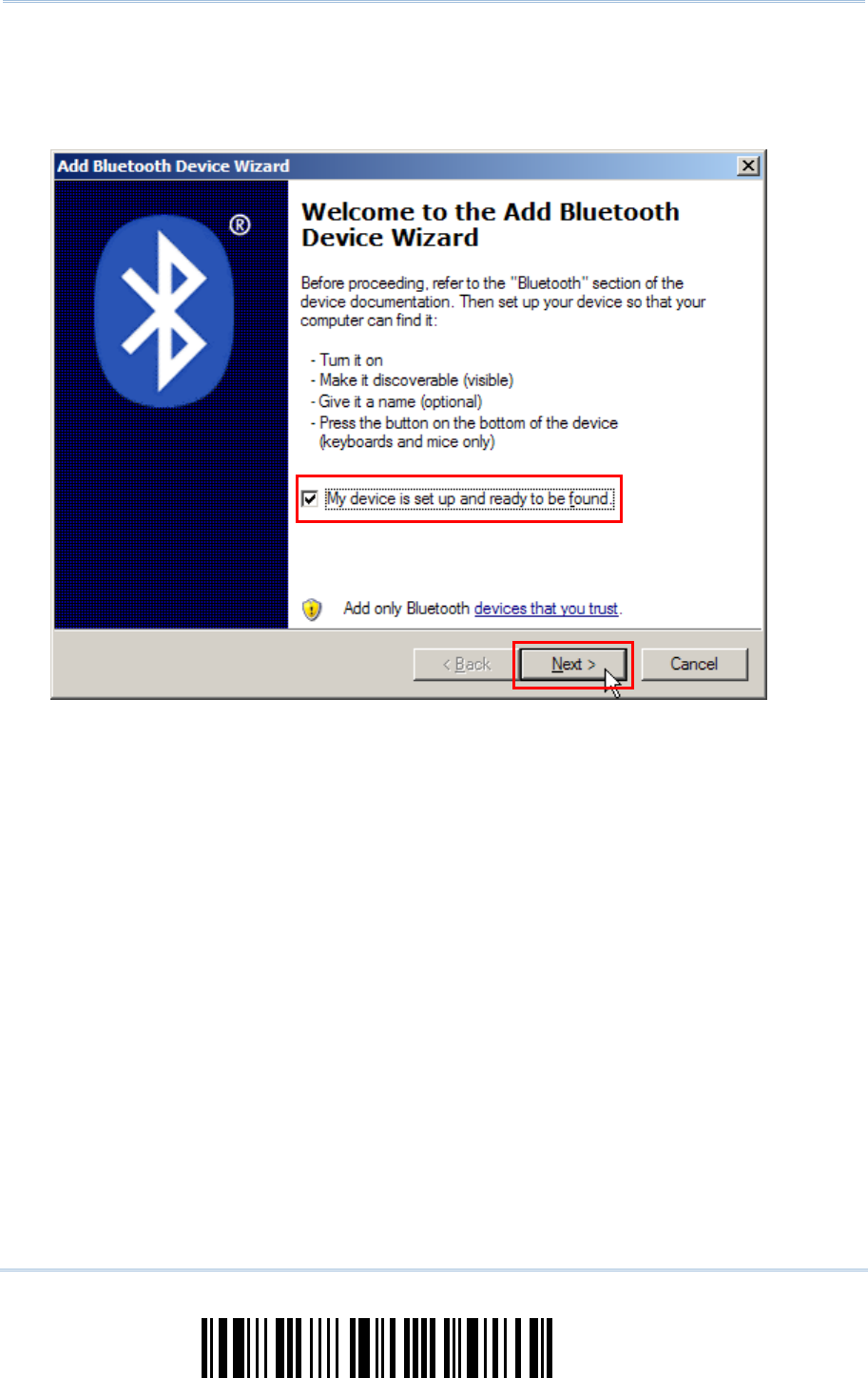
116
Enter Setup
1560/1562 Series Barcode Scanner
User Guide
4. Turn on the scanner with correct WPAN settings, such as select BT SPP or BT HID,
broadcasting enabled, authentication enabled, and PIN code specified, etc. Select the check
box of [My device is set up and ready to be found] on your computer.
5. Click [Next].
6. Wait for a few seconds for the Wizard to search available devices nearby.
The scanner will appear with its “serial number” as the device name. You may double-check
the “Serial Number” label on the scanner to ensure connecting with the correct scanner.
Select the target scanner. If the target scanner does not appear on the list, click [Search
Again] to refresh the list. The scanner might enter Suspend Mode now, and you can press the
trigger to have it active again (=discoverable). It will then stay active for a specified period of
time (2 minutes by default) and wait for PC to establish a connection.
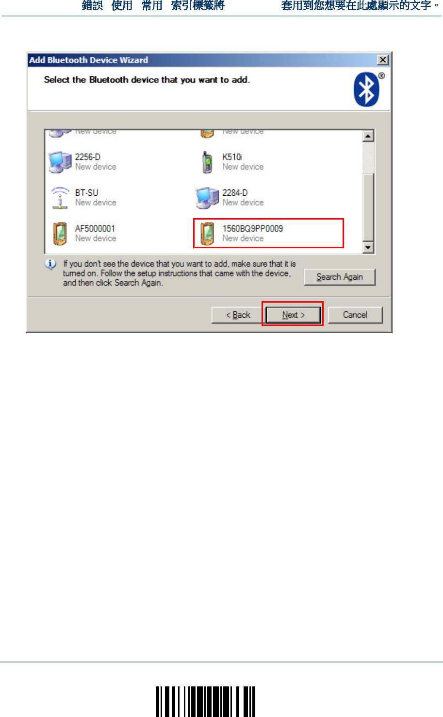
117
Update
Chapter 3
!
! !
!
[
[[
[
]
] ]
]
Heading 1
Heading 1 Heading 1
Heading 1
7. Click [Next].
8. Enter the passkey for authentication, which must be exactly the same as configured for the
scanner.
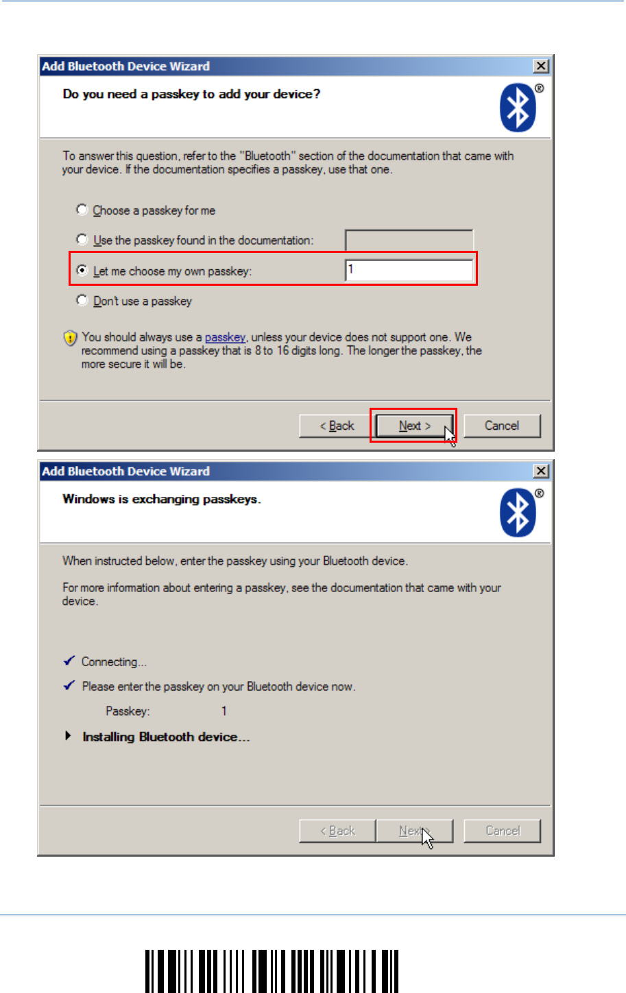
118
Enter Setup
1560/1562 Series Barcode Scanner
User Guide
9. Click [Next]. Wait for a few seconds for Windows to exchange passkeys.
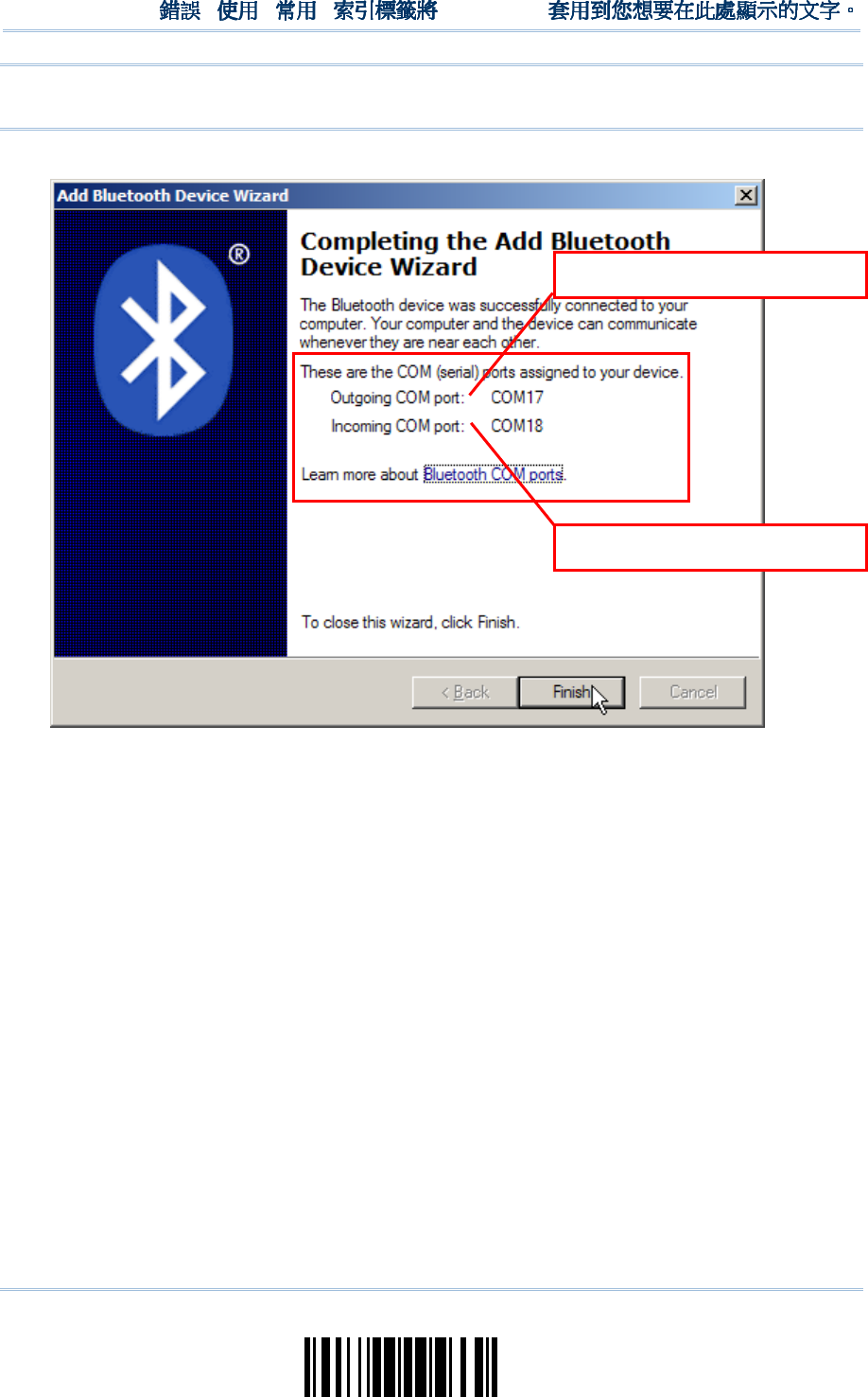
119
Update
Chapter 3
!
! !
!
[
[[
[
]
] ]
]
Heading 1
Heading 1 Heading 1
Heading 1
Note: When Bluetooth security is enabled without providing a pre-set PIN code, dynamic
input of PIN code is supported.
10.
Click [Finish].
1560 as BT SPP Slave
1560 as BT SPP Master
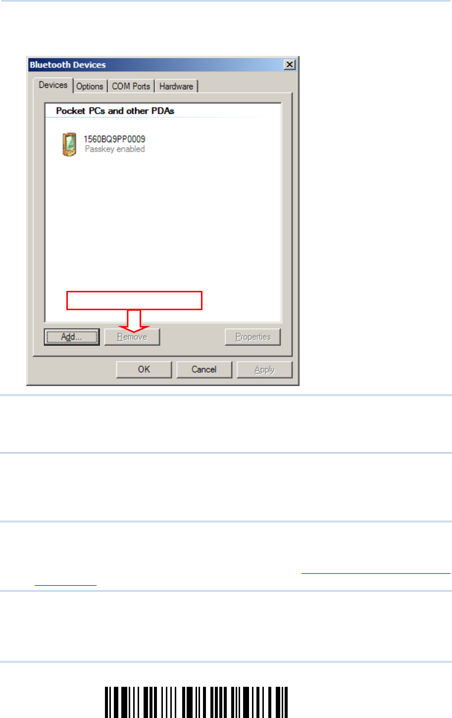
120
Enter Setup
1560/1562 Series Barcode Scanner
User Guide
11.
Now the target scanner will be listed as shown below.
You can have up to seven scanners connected to one computer at the same time.
Note: When any changes are made to authentication and PIN code on the scanner side,
or you want to change to use BT HID, it is suggested that you remove the scanner
from the paired device list (called unpairing) and go through the whole process to
re-establish the connection.
12.
Run the desired application on your computer, such as HyperTerminal.exe if using BT SPP or
Notepad.exe if using BT HID.
The status of the scanner listed on the device list will be updated to “Connected”, indicating
the WPAN connection is established successfully via the outgoing COM port if using BT SPP.
Note: Even though the scanner is connected to the host with authentication disabled (=
no PIN code required), the host may still request a PIN code while the application
is opening COM port. Dynamic input of PIN code is supported so that you may
input a matching PIN code on the scanner. Refer to Disable Authentication or Use
Random PIN.
Select and Remove
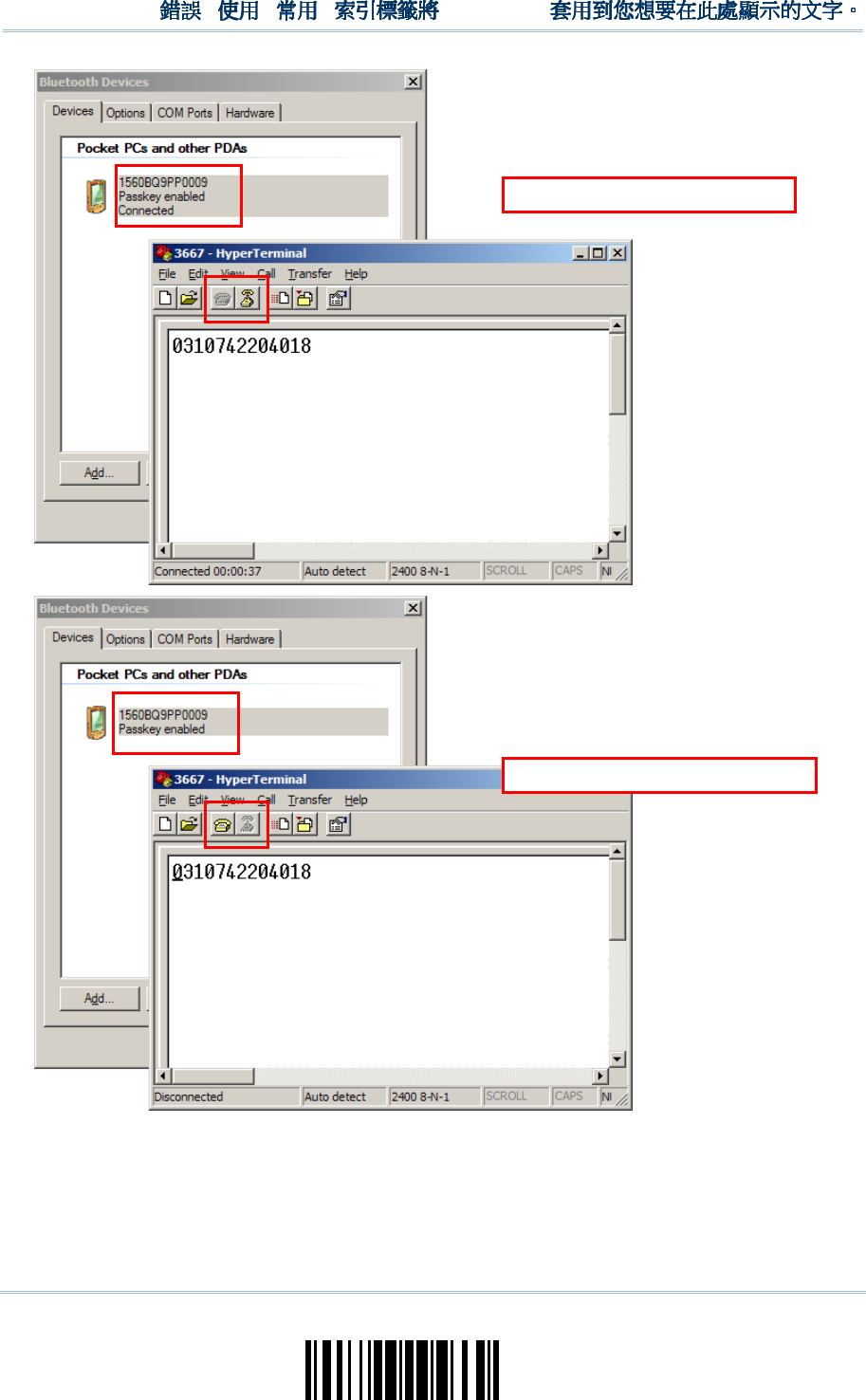
121
Update
Chapter 3
!
! !
!
[
[[
[
]
] ]
]
Heading 1
Heading 1 Heading 1
Heading 1
BT SPP Connected
BT SPP Disconnected
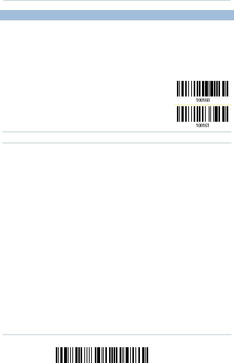
122
Enter Setup
1560/1562 Series Barcode Scanner
User Guide
3.2.4 SECURE SIMPLE
3.2.4 SECURE SIMPLE 3.2.4 SECURE SIMPLE
3.2.4 SECURE SIMPLE PAIRING (SSP)
PAIRING (SSP)PAIRING (SSP)
PAIRING (SSP)
Secure Simple Pairing (SSP), introduced in Bluetooth
®
Core Specification 2.1 + EDR, is a
new feature designed to ease the pairing process while keeping up the communication
security level. When connecting to a Bluetooth
®
host that supports Bluetooth
®
HID or
Bluetooth
®
SPP profile, you can implement the secure simple pairing process. This
function is enabled by default; the password dialog box won’t show up during the pairing
process.
Disable
*Enable
Note: Secure Simple Pairing only supports to devices with Bluetooth
®
v2.1 or later.

123
Update
In this chapter, a brief on the symbology settings is provided for your reference.
IN THIS CHAPTER
IN THIS CHAPTERIN THIS CHAPTER
IN THIS CHAPTER
4.1 Codabar ................................................................... 124
4.2 Code 25 – Industrial 25 ............................................. 126
4.3 Code 25 – Interleaved 25 ........................................... 129
4.4 Code 25 – Matrix 25 .................................................. 132
4.5 Code 39 ................................................................... 135
4.6 Trioptic Code 39 ....................................................... 137
4.7 Code 93 ................................................................... 137
4.8 Code 128 ................................................................. 137
4.9 EAN-8...................................................................... 138
4.10 EAN-13 .................................................................. 141
4.11 GS1-128 (EAN-128) ................................................ 144
4.12 ISBT 128 ................................................................ 145
4.13 MSI ....................................................................... 147
4.14 French Pharmacode ................................................. 149
4.15 Italian Pharmacode ................................................. 150
4.16 Plessey .................................................................. 151
4.17 GS1 DataBar (RSS Family) ....................................... 152
4.18 Telepen .................................................................. 157
4.19 UPC-A .................................................................... 160
4.20 UPC-E .................................................................... 162
4.21 Code 11 ................................................................. 165
Chapter
Chapter Chapter
Chapter
4
44
4
CHANGING
CHANGING CHANGING
CHANGING SYMBOLOGY SETTINGS
SYMBOLOGY SETTINGSSYMBOLOGY SETTINGS
SYMBOLOGY SETTINGS
124
Enter Setup
1560/1562
Series Barcode Scanner
User Guide
4.1 CODABAR
4.1 CODABAR4.1 CODABAR
4.1 CODABAR
*Enable
Disable
4.1.1 START/STOP CHA
4.1.1 START/STOP CHA4.1.1 START/STOP CHA
4.1.1 START/STOP CHARACTERS SELECTION
RACTERS SELECTIONRACTERS SELECTION
RACTERS SELECTION
Select one of the four different start/stop character pairs –
* abcd/abcd
abcd/tn*e
ABCD/ABCD
ABCD/TN*E
125
Update
Chapter 4
!
!!
!
[
[[
[
]
] ]
]
Heading 1
Heading 1 Heading 1
Heading 1
4.1.2 START/STOP TRA
4.1.2 START/STOP TRA4.1.2 START/STOP TRA
4.1.2 START/STOP TRANSMISSION
NSMISSIONNSMISSION
NSMISSION
Decide whether to include the start/stop characters in the data being transmitted.
Transmit Start/Stop
Characters
*Do Not Transmit
4.1.3 CLSI CONVERSIO
4.1.3 CLSI CONVERSIO4.1.3 CLSI CONVERSIO
4.1.3 CLSI CONVERSION
NN
N
When enabled, the CLSI editing strips the start/stop characters and inserts a space after
the first, fifth, and tenth characters of a 14-character Codabar barcode.
Apply CLSI Editing
*Do Not Apply
Note: The 14-character barcode length does not include start/stop characters.
4.1.4 SECUR
4.1.4 SECUR4.1.4 SECUR
4.1.4 SECURITY LEVEL
ITY LEVELITY LEVEL
ITY LEVEL
Security Level renders more decoding accuracy giving consideration to barcodes’ print
quality. Decide the security level for reading CodaBar barcodes.
Normal
*High
126
Enter Setup
1560/1562
Series Barcode Scanner
User Guide
4.2 CODE 25
4.2 CODE 254.2 CODE 25
4.2 CODE 25
–
––
–
INDUSTRIAL 25
INDUSTRIAL 25INDUSTRIAL 25
INDUSTRIAL 25
*Enable
Disable
4.2.1
4.2.1 4.2.1
4.2.1 START/
START/START/
START/STOP PATTERN SELECTI
STOP PATTERN SELECTISTOP PATTERN SELECTI
STOP PATTERN SELECTION
ONON
ON
This decides the readability of all 2 of 5 symbology variants. For example, flight tickets
actually use an Industrial 2 of 5 barcode but with Interleaved 2 of 5 start/stop pattern. In
order to read this barcode, the start/stop pattern selection parameter of Industrial 2 of 5
should set to "Interleaved 25".
*Industrial 25
Start/Stop Pattern
Interleaved 25
Start/Stop Pattern
Matrix 25
Start/Stop Pattern
4.2.2
4.2.2 4.2.2
4.2.2 VERIFY CHECK DIGIT
VERIFY CHECK DIGITVERIFY CHECK DIGIT
VERIFY CHECK DIGIT
Decide whether to verify the check digit. If incorrect, the barcode will not be accepted.
Verify Industrial 25
Check Digit
*Do Not Verify

127
Update
Chapter 4
!
! !
!
[
[[
[
]
] ]
]
Heading 1
Heading 1 Heading 1
Heading 1
4.2.3
4.2.3 4.2.3
4.2.3 TRANSMIT CHECK DIGIT
TRANSMIT CHECK DIGITTRANSMIT CHECK DIGIT
TRANSMIT CHECK DIGIT
Decide whether to include the check digit in the data being transmitted.
*Transmit
Industrial 25
Check Digit
Do Not Transmit
4.2.4 CODE LENGTH QU
4.2.4 CODE LENGTH QU4.2.4 CODE LENGTH QU
4.2.4 CODE LENGTH QUALIFICATION
ALIFICATIONALIFICATION
ALIFICATION
To prevent the "short scan" error, define the "Length Qualification" settings to ensure
that the correct barcode is read by qualifying the allowable code length.
If "Max/Min Length" is selected, the maximum length and the minimum length must
be specified. It only accepts those barcodes with lengths that fall between max/min
lengths specified.
If “Fixed Length” is selected, up to 2 fixed lengths can be specified.
1) Read the barcode to enable either Max. /Min. Length qualification or Fixed Length(s)
qualification.
*Enable Max./Min.
Length (0~127)…
Enable Fixed
Length(s)…
2) Read the barcode for Max. Length or Fixed Length 1, and follow steps 3~4.
Repeat steps 2~4 for Min. Length or Fixed Length 2.
128
Enter Setup
1560/1562
Series Barcode Scanner
User Guide
Max. Length (*127) or
Fixed Length 1
Min. Length (*4) or
Fixed Length 2
3) Read the “Decimal Value” barcode on page 241 for the desired length.
4) Read the “Validate” barcode on the same page to complete this setting.
4.2.5 SECURITY LEVEL
4.2.5 SECURITY LEVEL4.2.5 SECURITY LEVEL
4.2.5 SECURITY LEVEL
(1560P ONLY)
(1560P ONLY)(1560P ONLY)
(1560P ONLY)
Security Level renders more decoding accuracy giving consideration to barcodes’ print
quality. Decide the security level for reading Code 25 barcodes.
Normal
*High
129
Update
Chapter 4
!
! !
!
[
[[
[
]
] ]
]
Heading 1
Heading 1 Heading 1
Heading 1
4
44
4.3 CODE 25
.3 CODE 25 .3 CODE 25
.3 CODE 25 –
––
–
INTERLEAVED 25
INTERLEAVED 25INTERLEAVED 25
INTERLEAVED 25
*Enable
Disable
4.3.1 START/STOP PAT
4.3.1 START/STOP PAT4.3.1 START/STOP PAT
4.3.1 START/STOP PATTERN SELECTION
TERN SELECTIONTERN SELECTION
TERN SELECTION
This decides the readability of all 2 of 5 symbology variants. For example, flight tickets
actually use an Industrial 2 of 5 barcode but with Interleaved 2 of 5 start/stop pattern. In
order to read this barcode, the start/stop pattern selection parameter of Industrial 2 of 5
should set to "Interleaved 25".
Industrial 25
Start/Stop Pattern
*Interleaved 25
Start/Stop Pattern
Matrix 25
Start/Stop Pattern
130
Enter Setup
1560/1562
Series Barcode Scanner
User Guide
4.3.2
4.3.2 4.3.2
4.3.2 VERIFY CHECK DIGIT
VERIFY CHECK DIGITVERIFY CHECK DIGIT
VERIFY CHECK DIGIT
Decide whether to verify the check digit. If incorrect, the barcode will not be accepted.
Verify
Interleaved 25
Check Digit
*Do Not Verify
4.3.3
4.3.3 4.3.3
4.3.3 TRANSMIT CHECK DIGIT
TRANSMIT CHECK DIGITTRANSMIT CHECK DIGIT
TRANSMIT CHECK DIGIT
Decide whether to include the check digit in the data being transmitted.
*Transmit
Interleaved 25
Check Digit
Do Not Transmit
131
Update
Ch
apter 4
!
! !
!
[
[[
[
]
] ]
]
Heading 1
Heading 1 Heading 1
Heading 1
4.3.4 CODE LENGTH QU
4.3.4 CODE LENGTH QU4.3.4 CODE LENGTH QU
4.3.4 CODE LENGTH QUALIFICATION
ALIFICATIONALIFICATION
ALIFICATION
To prevent the "short scan" error, define the "Length Qualification" settings to ensure
that the correct barcode is read by qualifying the allowable code length.
If "Max/Min Length" is selected, the maximum length and the minimum length must
be specified. It only accepts those barcodes with lengths that fall between max/min
lengths specified.
If “Fixed Length” is selected, up to 2 fixed lengths can be specified.
1) Read the barcode to enable either Max. /Min. Length qualification or Fixed Length(s)
qualification.
*Enable Max./Min.
Length (0~127)…
Enable Fixed
Length(s)…
2) Read the barcode for Max. Length or Fixed Length 1, and follow steps 3~4.
Repeat steps 2~4 for Min. Length or Fixed Length 2.
Max. Length (*126) or
Fixed Length 1
Min. Length (*4) or
Fixed Length 2
3) Read the “Decimal Value” barcode on page 241 for the desired length.
4) Read the “Validate” barcode on the same page to complete this setting.
4.3.5 SESURITY LEVEL
4.3.5 SESURITY LEVEL4.3.5 SESURITY LEVEL
4.3.5 SESURITY LEVEL
(1560P ONLY)
(1560P ONLY)(1560P ONLY)
(1560P ONLY)
Security Level renders more decoding accuracy giving consideration to barcodes’ print
quality. Decide the security level for reading Code 25 barcodes. Please refer to 4.2.5
Security Level.
132
Enter Setup
1560/1562
Series Barcode Scanner
User Guide
4.4 CODE 25
4.4 CODE 25 4.4 CODE 25
4.4 CODE 25 –
––
–
MATRIX 25
MATRIX 25MATRIX 25
MATRIX 25
Enable
*Disable
4.4.1 START/STOP PAT
4.4.1 START/STOP PAT4.4.1 START/STOP PAT
4.4.1 START/STOP PATTERN SELECTION
TERN SELECTIONTERN SELECTION
TERN SELECTION
This decides the readability of all 2 of 5 symbology variants. For example, flight tickets
actually use an Industrial 2 of 5 barcode but with Interleaved 2 of 5 start/stop pattern. In
order to read this barcode, the start/stop pattern selection parameter of Industrial 2 of 5
should set to "Interleaved 25".
Industrial 25
Start/Stop Pattern
Interleaved 25
Start/Stop Pattern
*Matrix 25
Start/Stop Pattern

133
Update
Chapter 4
!
! !
!
[
[[
[
]
] ]
]
Heading 1
Heading 1 Heading 1
Heading 1
4.4.2
4.4.2 4.4.2
4.4.2 VERIFY CHECK DIGIT
VERIFY CHECK DIGITVERIFY CHECK DIGIT
VERIFY CHECK DIGIT
Decide whether to verify the check digit. If incorrect, the barcode will not be accepted.
Verify Matrix 25
Check Digit
*Do Not Verify
4.4.3
4.4.3 4.4.3
4.4.3 TRANSMIT CHECK DIGIT
TRANSMIT CHECK DIGITTRANSMIT CHECK DIGIT
TRANSMIT CHECK DIGIT
Decide whether to include the check digit in the data being transmitted.
*Transmit Matrix 25
Check Digit
Do Not Transmit
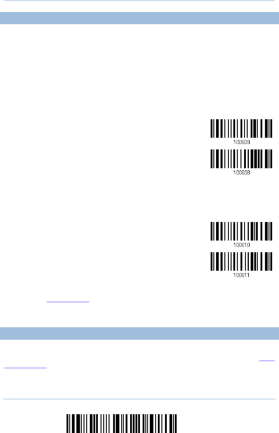
134
Enter Setup
1560/1562
Series Barcode Scanner
User Guide
4.4.4 CODE LENGTH QU
4.4.4 CODE LENGTH QU4.4.4 CODE LENGTH QU
4.4.4 CODE LENGTH QUALIFICATION
ALIFICATIONALIFICATION
ALIFICATION
To prevent the "short scan" error, define the "Length Qualification" settings to ensure
that the correct barcode is read by qualifying the allowable code length.
If "Max/Min Length" is selected, the maximum length and the minimum length must
be specified. It only accepts those barcodes with lengths that fall between max/min
lengths specified.
If “Fixed Length” is selected, up to 2 fixed lengths can be specified.
1) Read the barcode to enable either Max. /Min. Length qualification or Fixed Length(s)
qualification.
*Enable Max./Min.
Length (0~127)…
Enable Fixed
Length(s)…
2) Read the barcode for Max. Length or Fixed Length 1, and follow steps 3~4.
Repeat steps 2~4 for Min. Length or Fixed Length 2.
Max. Length (*127) or
Fixed Length 1
Min. Length (*4) or
Fixed Length 2
3) Read the “Decimal Value” barcode on page 241 for the desired length.
4) Read the “Validate” barcode on the same page to complete this setting.
4.4.5 SECURITY
4.4.5 SECURITY4.4.5 SECURITY
4.4.5 SECURITY
LEVEL
LEVELLEVEL
LEVEL
(1560P ONLY)
(1560P ONLY)(1560P ONLY)
(1560P ONLY)
Security Level renders more decoding accuracy giving consideration to barcodes’ print
quality. Decide the security level for reading Code 25 barcodes. Please refer to 4.2.5
Security Level.
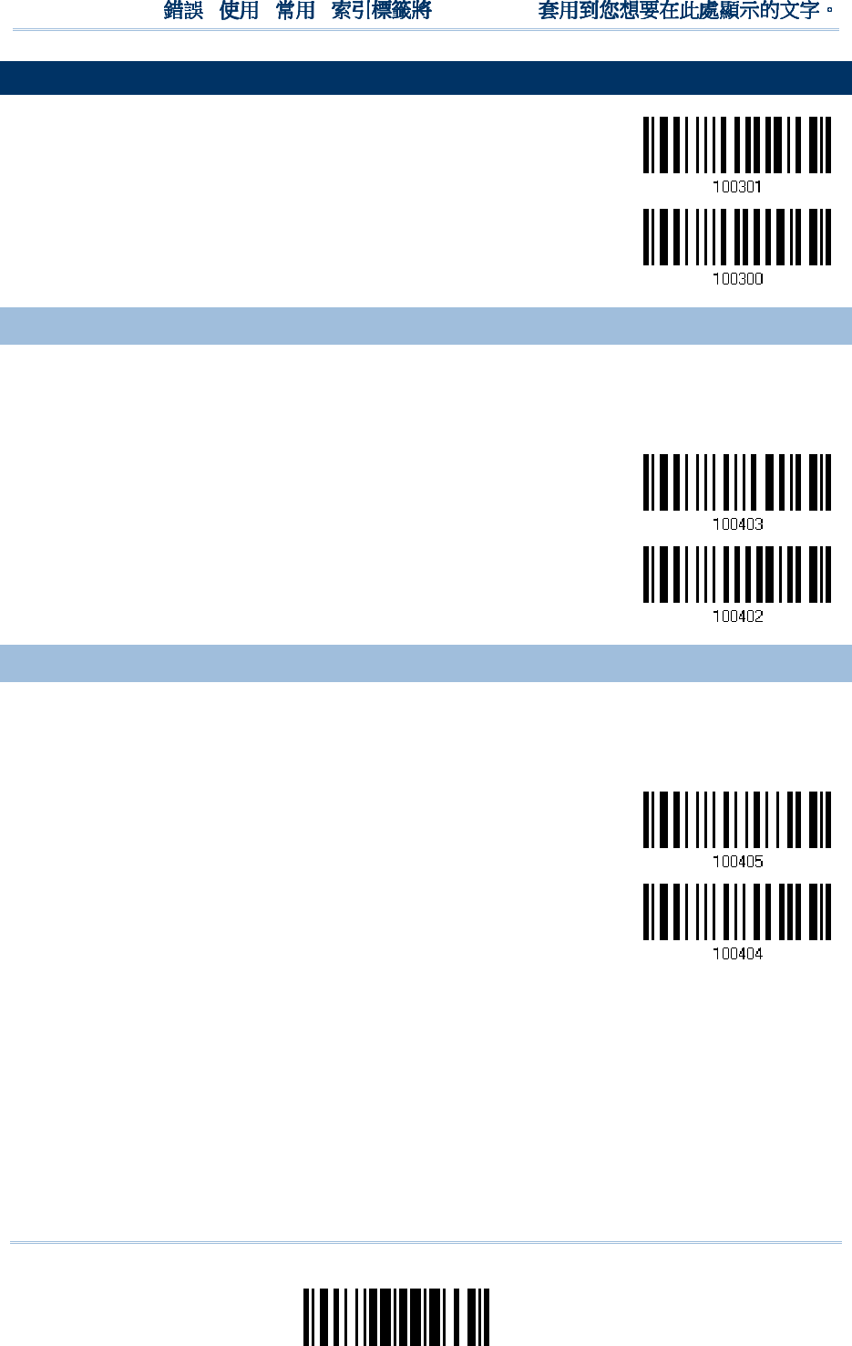
135
Update
Chapter 4
!
! !
!
[
[[
[
]
] ]
]
Heading 1
Heading 1 Heading 1
Heading 1
4.
4.4.
4.5
55
5
CODE 39
CODE 39CODE 39
CODE 39
*Enable
Disable
4.5.1 START
4.5.1 START4.5.1 START
4.5.1 START/S
/S/S
/STOP TRANSMISSION
TOP TRANSMISSIONTOP TRANSMISSION
TOP TRANSMISSION
Decide whether to include the start/stop characters in the data being transmitted.
Transmit Code 39
Start/Stop
Characters
*Do Not Transmit
4.5.2
4.5.2 4.5.2
4.5.2 VERIFY CHECK DIGIT
VERIFY CHECK DIGITVERIFY CHECK DIGIT
VERIFY CHECK DIGIT
Decide whether to verify check digit. If incorrect, the barcode will not be accepted.
Verify Code 39
Check Digit
*Do Not Verify
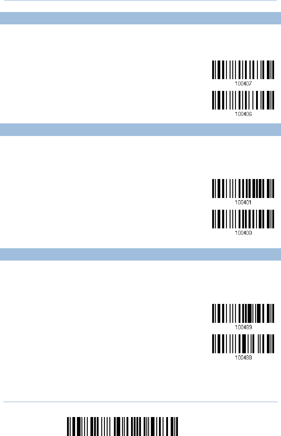
136
Enter Setup
1560/1562
Series Barcode Scanner
User Guide
4.5.3
4.5.3 4.5.3
4.5.3 TRANSMIT CHECK DIGIT
TRANSMIT CHECK DIGITTRANSMIT CHECK DIGIT
TRANSMIT CHECK DIGIT
Decide whether to include the check digit in the data being transmitted.
*Transmit Code 39
Check Digit
Do Not Transmit
4.5.4 STANDARD/FULL
4.5.4 STANDARD/FULL 4.5.4 STANDARD/FULL
4.5.4 STANDARD/FULL ASCII CODE 39
ASCII CODE 39ASCII CODE 39
ASCII CODE 39
Decide whether to support Code 39 Full ASCII that includes all the alphanumeric and
special characters.
Code 39 Full ASCII
*Standard Code 39
4.5.5 SECURITY LEVEL
4.5.5 SECURITY LEVEL4.5.5 SECURITY LEVEL
4.5.5 SECURITY LEVEL
Security Level renders more decoding accuracy giving consideration to barcodes’ print
quality. Decide the security level for reading Code 39 barcodes.
*Normal
High
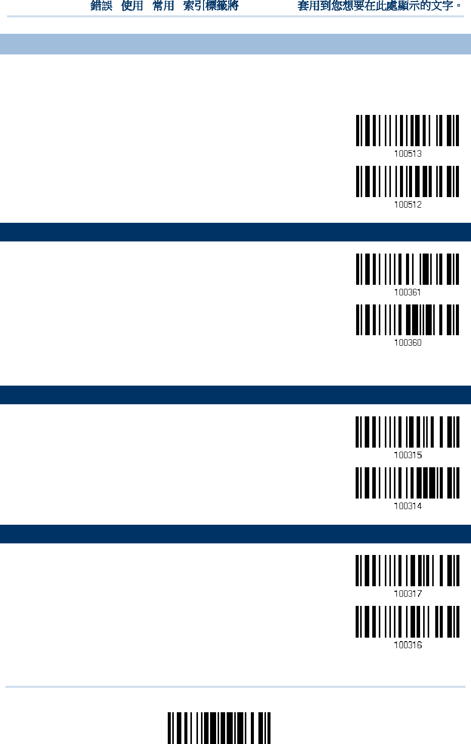
137
Update
Chapter 4
!
! !
!
[
[[
[
]
] ]
]
Heading 1
Heading 1 Heading 1
Heading 1
4.5.6 ASTERISK
4.5.6 ASTERISK4.5.6 ASTERISK
4.5.6 ASTERISKS
S S
S (*)
(*) (*)
(*) AS DATA CHARACTERS
AS DATA CHARACTERSAS DATA CHARACTERS
AS DATA CHARACTERS
Decide whether to take asterisk (*) as part of the data.
Enable
*Disable
4.6 TRIOPTIC CODE 39
4.6 TRIOPTIC CODE 394.6 TRIOPTIC CODE 39
4.6 TRIOPTIC CODE 39
Enable
*Disable
4.
4.4.
4.7
77
7
CODE 93
CODE 93CODE 93
CODE 93
*Enable
Disable
4.
4.4.
4.8
88
8
CODE 128
CODE 128CODE 128
CODE 128
*Enable
Disable
138
Enter Setup
1560/1562
Series Barcode Scanner
User Guide
4.
4.4.
4.8
88
8.1 SECURITY LEVEL
.1 SECURITY LEVEL.1 SECURITY LEVEL
.1 SECURITY LEVEL
Security Level renders more decoding accuracy giving consideration to barcodes’ print
quality. Decide the security level for reading Code 128 barcodes.
*Normal
High
4.
4.4.
4.9
99
9
EAN
EANEAN
EAN-
--
-8
88
8
EAN
EANEAN
EAN-
--
-8
88
8
*Enable EAN-
8
(No Addon)
Disable
EAN
EANEAN
EAN-
--
-8 Addon 2
8 Addon 28 Addon 2
8 Addon 2
Enable EAN-8 Addon 2
*Disable
EAN
EANEAN
EAN-
--
-8 Add
8 Add8 Add
8 Addon 5
on 5on 5
on 5
Enable EAN-8 Addon 5
*Disable
139
Update
Chapter 4
!
! !
!
[
[[
[
]
] ]
]
Heading 1
Heading 1 Heading 1
Heading 1
4.
4.4.
4.9
99
9.1
.1.1
.1
CONVERT TO EAN
CONVERT TO EANCONVERT TO EAN
CONVERT TO EAN-
--
-13
1313
13
Decide whether to expand the read EAN-8 barcode, as well as its addons, into EAN-13.
After conversion, the data follows EAN-13 format and is affected by EAN-13
programming selections (e.g. Check Digit).
Convert EAN-8 to
EAN-13
*Do Not Convert
4.
4.4.
4.9
99
9.
..
.2
2 2
2 TRANSMIT CHECK DIGIT
TRANSMIT CHECK DIGITTRANSMIT CHECK DIGIT
TRANSMIT CHECK DIGIT
Decide whether to include the check digit in the data being transmitted.
*Transmit EAN-8
Check Digit
Do Not Transmit
4.
4.4.
4.9
99
9.3 CONVERSION FO
.3 CONVERSION FO.3 CONVERSION FO
.3 CONVERSION FORMAT
RMATRMAT
RMAT
When converting EAN-8 to EAN-13, you can scan the barcode below to decide conversion
in default or GTIN-13 format.

140
Enter Setup
1560/1562
Series Barcode Scanner
User Guide
*Default Format
GTIN-13 Format
141
Update
Chapter 4
!
! !
!
[
[[
[
]
] ]
]
Heading 1
Heading 1 Heading 1
Heading 1
4.
4.4.
4.10
1010
10
EAN
EANEAN
EAN-
--
-13
1313
13
EAN
EANEAN
EAN-
--
-13
1313
13
*Enable EAN-
13
(No Addon)
Disable
EAN
EANEAN
EAN-
--
-13 Addon 2
13 Addon 213 Addon 2
13 Addon 2
Enable EAN-13 Addon 2
*Disable
EAN
EANEAN
EAN-
--
-13 Addon 5
13 Addon 513 Addon 5
13 Addon 5
Enable EAN-13 Addon 5
*Disable
142
Enter Setup
1560/1562
Series Barcode Scanner
User Guide
4.
4.4.
4.10
1010
10.1 ISBN CONVERSION
.1 ISBN CONVERSION.1 ISBN CONVERSION
.1 ISBN CONVERSION
Decide whether to convert the EAN-13 barcode, starting with 978 and 979, to ISBN.
Convert EAN-13 to
ISBN
*Do Not Convert
4.
4.4.
4.10
1010
10.2 ISSN CONVERSION
.2 ISSN CONVERSION.2 ISSN CONVERSION
.2 ISSN CONVERSION
Decide whether to convert the EAN-13 barcode, starting with 977 to ISSN.
Convert EAN-13 to
ISSN
*Do Not Convert
4.
4.4.
4.10
1010
10.3
.3 .3
.3 TRANSMIT CHECK DIGIT
TRANSMIT CHECK DIGITTRANSMIT CHECK DIGIT
TRANSMIT CHECK DIGIT
Decide whether to include the check digit in the data being transmitted.
*Transmit EAN-13
Check Digit
Do Not Transmit

143
Update
Chapter 4
!
! !
!
[
[[
[
]
] ]
]
Heading 1
Heading 1 Heading 1
Heading 1
4.10
4.104.10
4.10.
..
.4
44
4
S
SS
SECURITY LEVEL
ECURITY LEVELECURITY LEVEL
ECURITY LEVEL
Security Level renders more decoding accuracy giving consideration to barcodes’ print
quality. Decide the security level for reading EAN-13 barcodes.
*Normal
High
144
Enter Setup
1560/1562
Series Barcode Scanner
User Guide
4.
4.4.
4.1
11
11
11
1
GS1
GS1GS1
GS1-
--
-128 (
128 (128 (
128 (EAN
EANEAN
EAN-
--
-128
128128
128)
))
)
*Enable
Disable
Note: When this setting is disabled, GS1-128 barcodes used to be taken as Code 128.
However, starting from firmware version 1.01, GS1-128 barcodes can be decoded
only when this setting is enabled.
4.
4.4.
4.1
11
11
11
1.1 CODE ID TRANSMISS
.1 CODE ID TRANSMISS.1 CODE ID TRANSMISS
.1 CODE ID TRANSMISSION
IONION
ION
Decide whether to include the Code ID ("
]C1
") in the data being transmitted.
Transmit Code ID
*Do Not Transmit
4.
4.4.
4.1
11
11
11
1.2 FIELD SEPARATOR (
.2 FIELD SEPARATOR (.2 FIELD SEPARATOR (
.2 FIELD SEPARATOR (GS CHARACTER)
GS CHARACTER)GS CHARACTER)
GS CHARACTER)
Decide whether to apply a field separator (to convert the
FNC1
control character to human
readable character).
Enable Field
Separator…
1) Read the barcode above to enable field separator.
2) Read the “Hexadecimal Value” barcode on page 242 for the desired character string.
3) Read the “Validate” barcode to complete this setting.
Note: GS1-128 barcodes start with the
FNC1
control character to distinguish themselves
from other uses of Code 128.
FNC1
is also used to separate data fields in the
GS1-128 barcodes.
145
Update
Chapter 4
!
! !
!
[
[[
[
]
] ]
]
Hea
HeaHea
Hea
ding 1
ding 1 ding 1
ding 1
4.1
4.14.1
4.11
11
1.3
.3.3
.3
GS1 FORMATTING
GS1 FORMATTINGGS1 FORMATTING
GS1 FORMATTING
Decide whether to enable GS1 formatting for GS1-128.
Enable
*Disable
4.1
4.14.1
4.11
11
1.4 APPLICATION ID
.4 APPLICATION ID.4 APPLICATION ID
.4 APPLICATION ID
MARK
MARKMARK
MARK
Decide whether to add an application ID mark (1 character) to the left (AIMark1) or right
(AIMark2) of an application ID (AI) for the purpose of labeling it when formatting the
GS1 data.
AIMark1
AIMark2
1) Read the barcode above to add a mark to the left (AIMark1)/right (AIMark2) of an
application ID.
2) Read the “Hexadecimal Value” barcode on page 242 for the desired character string.
Read ‘00’ if you want to remove the AI mark.
3) Read the “Validate” barcode to complete this setting.
146
Enter Setup
1560/1562
Series Barcode Scanner
User Guide
4.1
4.14.1
4.12
22
2
ISBT 128
ISBT 128ISBT 128
ISBT 128
*Enable
Disable
4
44
4.1
.1.1
.12
22
2.1 ISBT CONCATENATIO
.1 ISBT CONCATENATIO.1 ISBT CONCATENATIO
.1 ISBT CONCATENATION
NN
N
Decide whether to decode and concatenate pairs of ISBT barcodes.
Auto-discriminate ISBT Concatenation
It decodes and concatenates pairs of ISBT barcodes immediately. If only a single ISBT
barcode is present, the scanner must decode 10 times before transmitting its data to
confirm that there is no additional ISBT barcode.
Enable ISBT Concatenation
There must be two ISBT barcodes in order for the scanner to decode and perform
concatenation. It does not decode single ISBT barcodes.
Disable ISBT Concatenation
It will not concatenate pairs of ISBT barcodes it encounters.
*Auto-discriminate
Enable
Disable
147
Update
Chapter 4
!
! !
!
[
[[
[
]
] ]
]
Heading 1
Heading 1 Heading 1
Heading 1
4.
4.4.
4.1
11
13
33
3
MSI
MSIMSI
MSI
Enable
*Disable
4.
4.4.
4.1
11
13
33
3.1
.1 .1
.1 VERIFY CHECK DIGIT
VERIFY CHECK DIGITVERIFY CHECK DIGIT
VERIFY CHECK DIGIT
Select one of the three calculations to verify check digit when decoding barcodes. If
incorrect, the barcode will not be accepted.
*Single Modulo 10
Double Modulo 10
Modulo 10 & 11
4.1
4.14.1
4.13
33
3.
..
.2
2 2
2 TRANSMIT CHECK DIGIT
TRANSMIT CHECK DIGITTRANSMIT CHECK DIGIT
TRANSMIT CHECK DIGIT
Decide whether to include the check digit in the data being transmitted.
*Last Digit Not
Transmitted
Both Digits
Transmitted
Both Digits
Not Transmitted
148
Enter Setup
1560/1562
Series Barcode Scanner
User Guide
4.
4.4.
4.1
11
13
33
3.3 CODE LENGTH QUALI
.3 CODE LENGTH QUALI.3 CODE LENGTH QUALI
.3 CODE LENGTH QUALIFICATION
FICATIONFICATION
FICATION
To prevent the "short scan" error, define the "Length Qualification" settings to ensure
that the correct barcode is read by qualifying the allowable code length.
If "Max/Min Length" is selected, the maximum length and the minimum length must
be specified. It only accepts those barcodes with lengths that fall between max/min
lengths specified.
If “Fixed Length” is selected, up to 2 fixed lengths can be specified.
1) Read the barcode to enable either Max. /Min. Length qualification or Fixed Length(s)
qualification.
*Enable Max./Min.
Length (0~127)…
Enable Fixed
Length(s)…
2) Read the barcode for Max. Length or Fixed Length 1, and follow steps 3~4.
Repeat steps 2~4 for Min. Length or Fixed Length 2.
Max. Length (*127) or
Fixed Length 1
Min. Length (*4) or
Fixed Length 2
3) Read the “Decimal Value” barcode on page 241 for the desired length.
4) Read the “Validate” barcode on the same page to complete this setting.
149
Update
Chapter 4
!
! !
!
[
[[
[
]
] ]
]
Heading 1
Heading 1 Heading 1
Heading 1
4.1
4.14.1
4.14
44
4
FRENCH
FRENCH FRENCH
FRENCH PHARMACODE
PHARMACODEPHARMACODE
PHARMACODE
Enable
*Disable
4.1
4.14.1
4.14
44
4.1
.1.1
.1
TRANSMIT CHECK DIGIT
TRANSMIT CHECK DIGITTRANSMIT CHECK DIGIT
TRANSMIT CHECK DIGIT
Decide whether to include the check digit in the data being transmitted.
*Transmit
French Pharmacode
Check Digit
Do Not Transmit
150
Enter Setup
1560/1562
Series Barcode Scanner
User Guide
4.1
4.14.1
4.15
55
5
ITALIAN PHARMACODE
ITALIAN PHARMACODEITALIAN PHARMACODE
ITALIAN PHARMACODE
Enable
*Disable
4.1
4.14.1
4.15
55
5.1
.1.1
.1
TRANSMIT CHECK DIGIT
TRANSMIT CHECK DIGITTRANSMIT CHECK DIGIT
TRANSMIT CHECK DIGIT
Decide whether to include the check digit in the data being transmitted.
*Transmit
Italian Pharmacode
Check Digit
Do Not Transmit
151
Update
Chapter 4
!
! !
!
[
[[
[
]
]]
]
Heading 1
Heading 1 Heading 1
Heading 1
4.1
4.14.1
4.16
66
6
PLESSEY
PLESSEYPLESSEY
PLESSEY
Enable
*Disable
4.1
4.14.1
4.16
66
6.1 CONVERT TO UK PLE
.1 CONVERT TO UK PLE.1 CONVERT TO UK PLE
.1 CONVERT TO UK PLESSEY
SSEYSSEY
SSEY
Decide whether to change each occurrence of the character 'A' to character 'X' in the
decoded data.
Convert to UK Plessey
*Do Not Convert
4.1
4.14.1
4.16
66
6.2
.2 .2
.2 TRANSMIT CHECK DIGIT
TRANSMIT CHECK DIGITTRANSMIT CHECK DIGIT
TRANSMIT CHECK DIGIT
Decide whether to include the two check digits in the data being transmitted.
*Transmit Plessey
Check Digits
Do Not Transmit
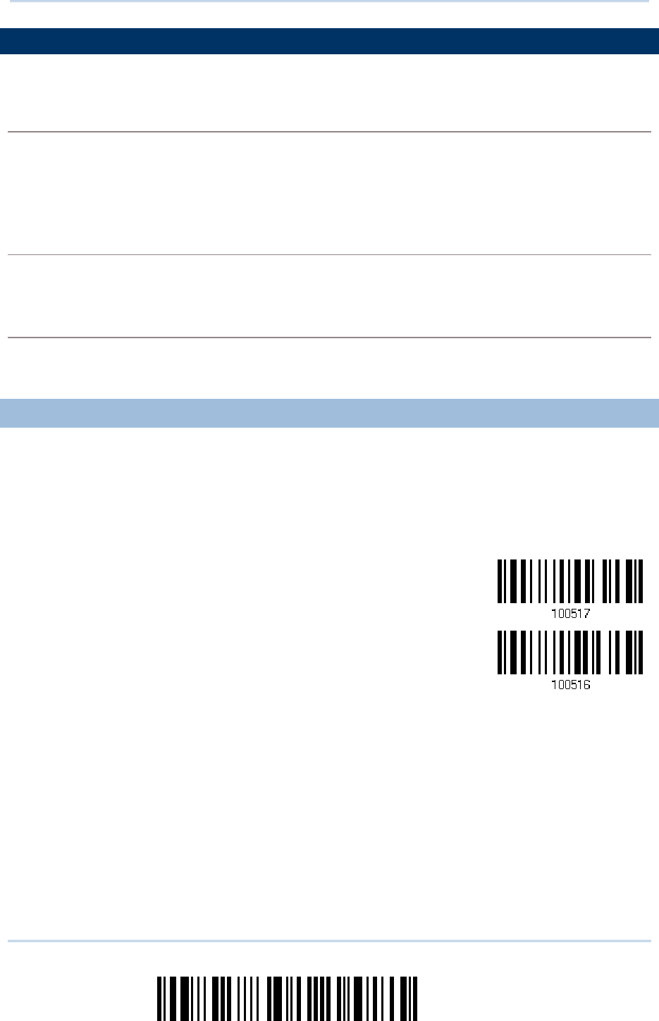
152
Enter Setup
1560/1562
Series Barcode Scanner
User Guide
4.1
4.14.1
4.17
77
7
GS1 DA
GS1 DAGS1 DA
GS1 DATA
TATA
TAB
BB
BAR (
AR (AR (
AR (RSS FAMILY
RSS FAMILYRSS FAMILY
RSS FAMILY)
))
)
It is categorized into three groups:
Group I
Group I Group I
Group I —
——
—
GS1 DataBar Omnidirectional (RSS
GS1 DataBar Omnidirectional (RSSGS1 DataBar Omnidirectional (RSS
GS1 DataBar Omnidirectional (RSS-
--
-14)
14)14)
14)
This group consists of the following:
GS1 DataBar Omnidirectional
GS1 DataBar Truncated
GS1 DataBar Stacked
GS1 DataBar Stacked Omnidirectional
Grou
GrouGrou
Group II
p IIp II
p II
—
——
—
GS1 DataBar Expanded (RSS Expanded)
GS1 DataBar Expanded (RSS Expanded)GS1 DataBar Expanded (RSS Expanded)
GS1 DataBar Expanded (RSS Expanded)
This group consists of the following:
GS1 DataBar Expanded
GS1 DataBar Expanded Stacked
Group III
Group III Group III
Group III —
——
—
GS1 DataBar Limited (RSS Limited)
GS1 DataBar Limited (RSS Limited)GS1 DataBar Limited (RSS Limited)
GS1 DataBar Limited (RSS Limited)
This group consists of the following:
GS1 DataBar Limited
4.1
4.14.1
4.17
77
7.1 CODE I
.1 CODE I.1 CODE I
.1 CODE ID SELECTION
D SELECTIOND SELECTION
D SELECTION
Select a desired Code ID to use:
“
]e0
“ (GS1 DataBar Code ID)
“
]C1
” (GS1-128 Code ID)
Use “]C1”
*Use “]e0”
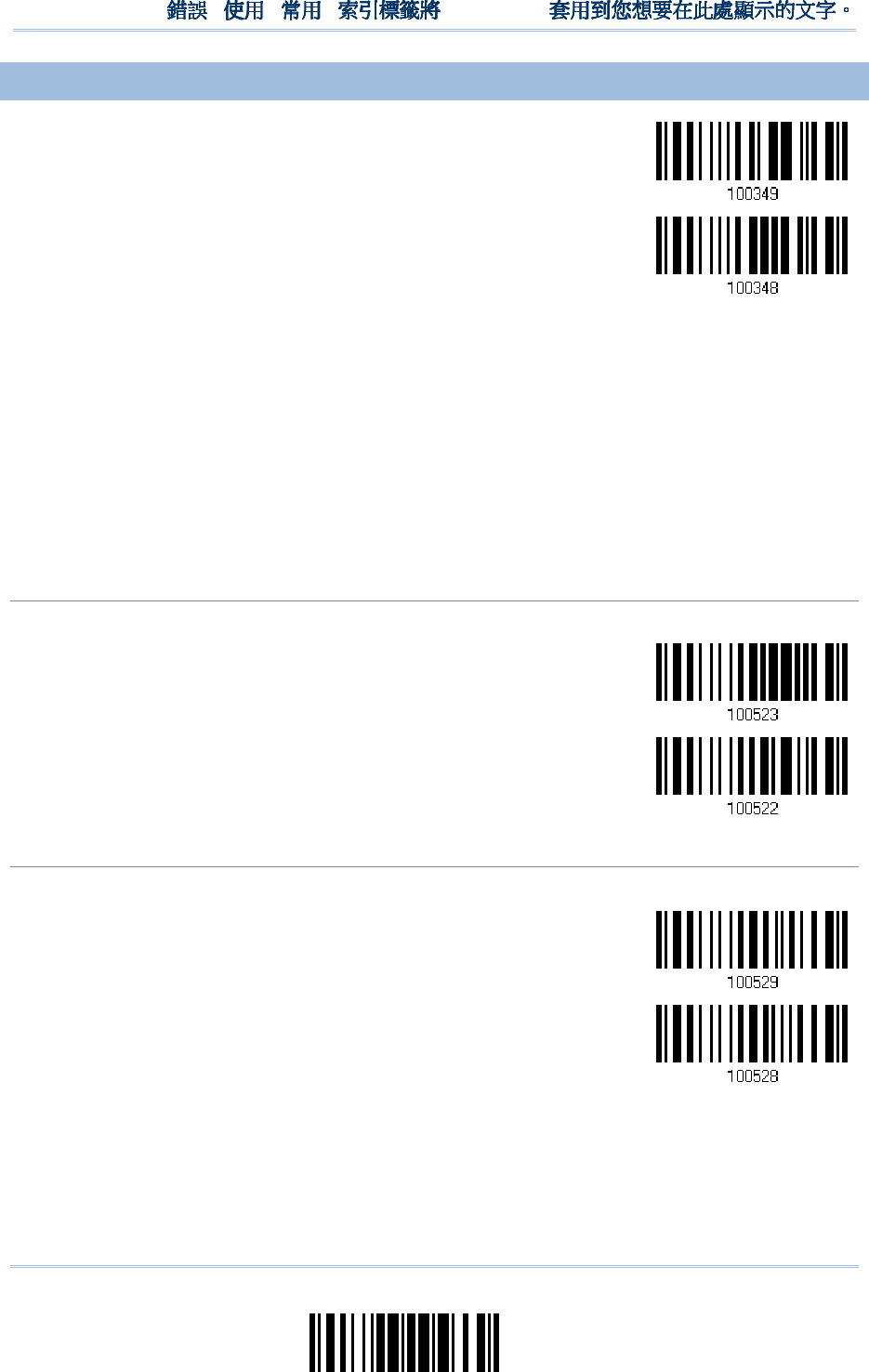
153
Update
Chapter 4
!
! !
!
[
[[
[
]
] ]
]
Heading 1
Heading 1 Heading 1
Heading 1
4.1
4.14.1
4.17
77
7.2
.2 .2
.2 GS1 DATA
GS1 DATAGS1 DATA
GS1 DATAB
BB
BAR OMNIDIRECTIONAL (
AR OMNIDIRECTIONAL (AR OMNIDIRECTIONAL (
AR OMNIDIRECTIONAL (RSS
RSSRSS
RSS-
--
-14)
14)14)
14)
Enable RSS-
14 &
RSS Expanded
(Groups I, II)
*Disable
The settings below apply to Group I symbologies only:
GS1 DataBar Omnidirectional
GS1 DataBar Truncated
GS1 DataBar Stacked
GS1 DataBar Stacked Omnidirectional
Transmit Code ID
Transmit Code IDTransmit Code ID
Transmit Code ID
Decide whether to include the Code ID in the data being transmitted.
*Transmit RSS-14
Code ID
Do Not Transmit
Transmit Application ID
Transmit Application IDTransmit Application ID
Transmit Application ID
Decide whether to include the Application ID ("01") in the data being transmitted.
*Transmit RSS-14
Application ID
Do Not Transmit

154
Enter Setup
1560/1562
Series Barcode Scanner
User Guide
Transmit Check Digit
Transmit Check DigitTransmit Check Digit
Transmit Check Digit
Decide whether to include the check digit in the data being transmitted.
*Transmit RSS-14
Check Digit
Do Not Transmit
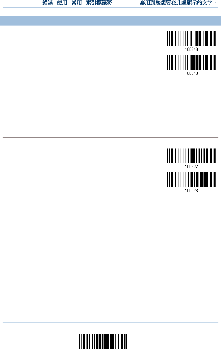
155
Update
Chapter 4
!
! !
!
[
[[
[
]
] ]
]
Heading 1
Heading 1 Heading 1
Heading 1
4.1
4.14.1
4.17
77
7.3
.3 .3
.3 GS1 DATA
GS1 DATAGS1 DATA
GS1 DATAB
BB
BAR EXPANDED (
AR EXPANDED (AR EXPANDED (
AR EXPANDED (RSS EXPANDED
RSS EXPANDEDRSS EXPANDED
RSS EXPANDED)
))
)
Enable RSS-
14 &
RSS Expanded
(Groups I, II)
*Disable
The settings below apply to Group II symbologies only:
GS1 DataBar Expanded
GS1 DataBar Expanded Stacked
Transmit Code ID
Transmit Code IDTransmit Code ID
Transmit Code ID
Decide whether to include the Code ID in the data being transmitted.
*Transmit
RSS Expanded Code ID
Do Not Transmit
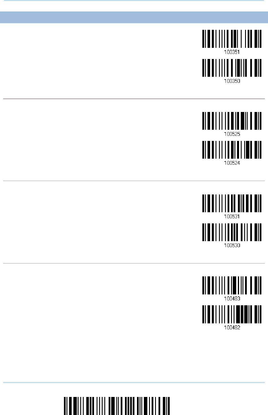
156
Enter Setup
1560/1562
Series Barcode Scanner
User Guide
4
44
4.1
.1.1
.17
77
7.4
.4 .4
.4 GS1 DATA
GS1 DATAGS1 DATA
GS1 DATAB
BB
BAR LIMITED (
AR LIMITED (AR LIMITED (
AR LIMITED (RSS LIMITED
RSS LIMITEDRSS LIMITED
RSS LIMITED)
))
)
Enable RSS Limited
(Group III)
*Disable
Transmit Code ID
Transmit Code IDTransmit Code ID
Transmit Code ID
Decide whether to include the Code ID in the data being transmitted.
*Transmit
RSS Limited Code ID
Do Not Transmit
Transmit A
Transmit ATransmit A
Transmit Application ID
pplication IDpplication ID
pplication ID
Decide whether to include the Application ID ("01") in the data being transmitted.
*Transmit
RSS Limited
Application ID
Do Not Transmit
Transmit Check Digit
Transmit Check DigitTransmit Check Digit
Transmit Check Digit
Decide whether to include the check digit in the data being transmitted.
*Transmit
RSS Limited
Check Digit
Do Not Transmit
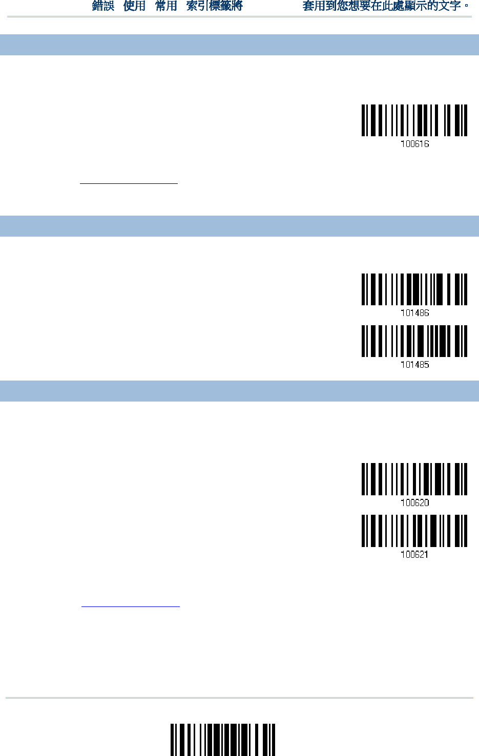
157
Update
Chapter 4
!
! !
!
[
[[
[
]
] ]
]
Heading 1
Heading 1 Heading 1
Heading 1
4.1
4.14.1
4.17
77
7.5 FIELD SEPARATOR
.5 FIELD SEPARATOR.5 FIELD SEPARATOR
.5 FIELD SEPARATOR
(GS CHARACTER)
(GS CHARACTER)(GS CHARACTER)
(GS CHARACTER)
Decide whether to apply a field separator (to convert the GS control character to human
readable character).
Enable Field
Separator…
1) Read the barcode above to enable field separator.
2) Read the “Hexadecimal Value” barcode on page 242 for the desired character string.
3) Read the “Validate” barcode to complete this setting.
4.1
4.14.1
4.17.
7.7.
7.6 GS1 FORMATTING
6 GS1 FORMATTING6 GS1 FORMATTING
6 GS1 FORMATTING
Decide whether to enable GS1 formatting for GS1 DataBar (RSS family).
Enable
*Disable
4.1
4.14.1
4.17
77
7.7 APPLICATION ID
.7 APPLICATION ID .7 APPLICATION ID
.7 APPLICATION ID M
MM
MARK
ARKARK
ARK
Decide whether to add an application ID mark (1 character) to the left (AIMark1) or right
(AIMark2) of an application ID (AI) for the purpose of labeling it when formatting the
GS1 data.
AIMark1
AIMark2
1) Read the barcode above to add a mark to the left (AIMark1)/right (AIMark2) of an
application ID.
2) Read the “Hexadecimal Value” barcode on page 242 for the desired character string.
Read '00' if you want to remove the AI mark.
3) Read the “Validate” barcode to complete this setting.

158
Enter Setup
1560/1562
Series Barcode Scanner
User Guide
4.1
4.14.1
4.17
77
7.8 SECURITY LEVEL
.8 SECURITY LEVEL.8 SECURITY LEVEL
.8 SECURITY LEVEL
Security Level renders more decoding accuracy giving consideration to barcodes’ print
quality. Decide the security level for reading GS1 DataBar barcodes.
*Normal
High
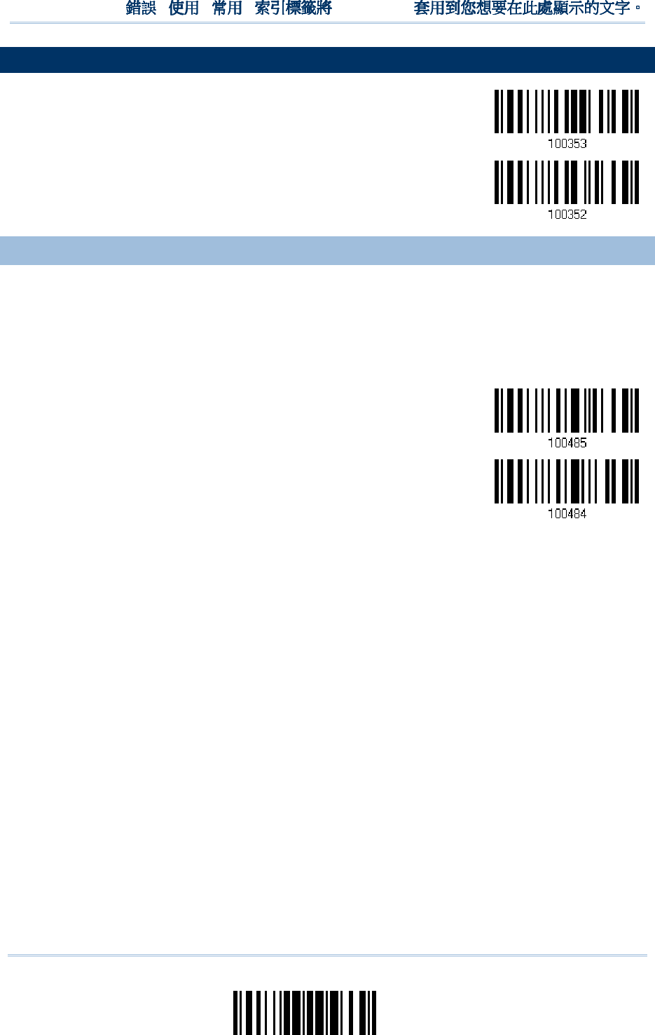
159
Update
Chapter 4
!
! !
!
[
[[
[
]
] ]
]
Heading 1
Heading 1 Heading 1
Heading 1
4.1
4.14.1
4.18
88
8
TELEPEN
TELEPENTELEPEN
TELEPEN
Enable Telepen
*Disable
4.1
4.14.1
4.18
88
8.1 TELEPEN OUTPUT
.1 TELEPEN OUTPUT .1 TELEPEN OUTPUT
.1 TELEPEN OUTPUT –
––
–
FULL ASCII/NU
FULL ASCII/NUFULL ASCII/NU
FULL ASCII/NUMERIC
MERICMERIC
MERIC
Decide whether to support Telepen in full ASCII code. By default, it supports ASCII
mode.
AIM Telepen (Full ASCII) includes all the alphanumeric and special characters.
Original Telepen
(Numeric)
*AIM Telepen
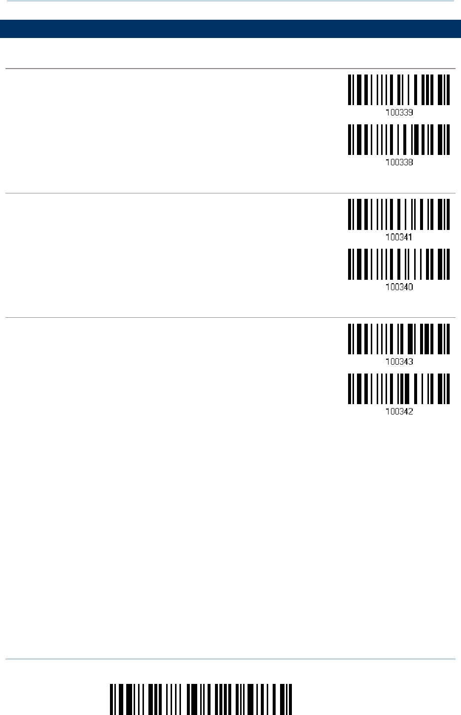
160
Enter Setup
1560/1562
Series Barcode Scanner
User Guide
4.1
4.14.1
4.19
99
9
UPC
UPCUPC
UPC-
--
-A
AA
A
UPC
UPCUPC
UPC-
--
-A
AA
A
*Enable UPC-
A
(No Addon)
Disable
UPC
UPCUPC
UPC-
--
-A Addon 2
A Addon 2A Addon 2
A Addon 2
Enable UPC-A Addon 2
*Disable
UPC
UPCUPC
UPC-
--
-A Addon 5
A Addon 5A Addon 5
A Addon 5
Enable UPC-A Addon 5
*Disable
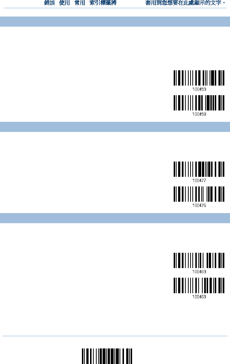
161
Update
Chapter 4
!
! !
!
[
[[
[
]
] ]
]
Heading 1
Heading 1 Heading 1
Heading 1
4.1
4.14.1
4.19
99
9.1 CONVERT TO EAN
.1 CONVERT TO EAN.1 CONVERT TO EAN
.1 CONVERT TO EAN-
--
-13
1313
13
Decide whether to expand the read UPC-A barcode, as well as its addons, into EAN-13.
After conversion, the data follows EAN-13 format and is affected by EAN-13
programming selections (e.g. Check Digit).
Convert UPC-A to
EAN-13
*Do Not Convert
4.1
4.14.1
4.19
99
9.2 SYSTEM NUMBER TRA
.2 SYSTEM NUMBER TRA.2 SYSTEM NUMBER TRA
.2 SYSTEM NUMBER TRANSMISSION
NSMISSIONNSMISSION
NSMISSION
Decide whether to include the system number in the data being transmitted.
*Transmit UPC-A
System Number
Do Not Transmit
4.1
4.14.1
4.19
99
9.3
.3 .3
.3 TRANSMIT CHECK DIGIT
TRANSMIT CHECK DIGITTRANSMIT CHECK DIGIT
TRANSMIT CHECK DIGIT
Decide whether to include the check digit in the data being transmitted.
*Transmit UPC-A
Check Digit
Do Not Transmit
162
Enter Setup
1560/1562
Series Barcode Scanner
User Guide
4.
4.4.
4.20
2020
20
UPC
UPCUPC
UPC-
--
-E
EE
E
UPC
UPCUPC
UPC-
--
-E
EE
E
*Enable UPC-
E
(No Addon)
Disable
UPC
UPCUPC
UPC-
--
-E Addon 2
E Addon 2E Addon 2
E Addon 2
Enable UPC-E Addon 2
*Disable
UPC
UPCUPC
UPC-
--
-E Addon 5
E Addon 5E Addon 5
E Addon 5
Enable UPC-E Addon 5
*Disable
163
Update
Chapter 4
!
! !
!
[
[[
[
]
] ]
]
Heading 1
Heading 1 Heading 1
Heading 1
4.
4.4.
4.20
2020
20.1 SYSTEM NUMBER SEL
.1 SYSTEM NUMBER SEL.1 SYSTEM NUMBER SEL
.1 SYSTEM NUMBER SELECTION
ECTIONECTION
ECTION
Decide whether to decode the ordinary UPC-E barcodes only or both UPC-E0 and UPC-E1
barcodes.
System number
0
enabled for decoding UPC-E0 barcodes.
System number
1
enabled for decoding UPC-E1 barcodes.
System Number 0 & 1
*System Number 0 Only
Warning: Because of the way system number 1 is encoded, if both system numbers
are enabled, the user might suffer from short scanning UPC-A or EAN-13
barcodes into UPC-E1 barcodes.
4.
4.4.
4.20
2020
20.2 CONVERT TO UPC
.2 CONVERT TO UPC.2 CONVERT TO UPC
.2 CONVERT TO UPC-
--
-A
AA
A
Decide whether to expand the read UPC-E barcode, as well as its addons, into UPC-A.
After conversion, the data follows UPC-A format and is affected by UPC-A
programming selections (e.g. System Number, Check Digit).
Convert UPC-E to
UPC-A
*Do Not Convert
164
Enter Setup
1560/1562
Series Barcode Scanner
User Guide
4.
4.4.
4.20
2020
20.3 SYSTEM NUMBER TRA
.3 SYSTEM NUMBER TRA.3 SYSTEM NUMBER TRA
.3 SYSTEM NUMBER TRANSMISSION
NSMISSIONNSMISSION
NSMISSION
Decide whether to include the system number in the data being transmitted.
Transmit UPC-E
System Number
*Do Not Transmit
4.
4.4.
4.20
2020
20.4
.4 .4
.4 TRANSMIT CHECK DIGIT
TRANSMIT CHECK DIGITTRANSMIT CHECK DIGIT
TRANSMIT CHECK DIGIT
Decide whether to include the check digit in the data being transmitted.
*Transmit UPC-E
Check Digit
Do Not Transmit
165
Update
Chapter 4
!
! !
!
[
[[
[
]
] ]
]
Heading 1
Heading 1 Heading 1
Heading 1
4.21
4.214.21
4.21
CODE 11
CODE 11CODE 11
CODE 11
Enable
*Disable
4.21
4.214.21
4.21.1
.1 .1
.1 VERIF
VERIFVERIF
VERIFY CHECK DIGIT
Y CHECK DIGITY CHECK DIGIT
Y CHECK DIGIT
Select one of the verification when decoding barcodes. If incorrect, the barcode will not
be accepted.
None
Double
Single
*Auto
166
Enter Setup
1560/1562
Series Barcode Scanner
User Guide
4.21
4.214.21
4.21.
..
.2
22
2
TRANSMIT CHECK DIGIT
TRANSMIT CHECK DIGITTRANSMIT CHECK DIGIT
TRANSMIT CHECK DIGIT
Decide whether to include the check digit in the data being transmitted.
*Transmit Check
Digit
Do Not Transmit
4.21.
4.21.4.21.
4.21.3
33
3
SECURITY LEVEL
SECURITY LEVELSECURITY LEVEL
SECURITY LEVEL
Security Level renders more decoding accuracy giving consideration to barcodes’ print
quality. Decide the security level for reading Code 11 barcodes.
Normal
*High

167
Update
You may configure in which format the collected data will be output to the host computer.
Barcode read by the scanner will be processed in the following sequence –
1) Perform character substitution on the data scanned.
2) Add Code ID and Length Code to the front of the data:
[Code ID][Length Code][Data]
3) Process the whole data in step 2 with user formats. Data is now divided into fields by
user specified rules. Refer to Chapter 6 Applying Formats for Data Editing.
4) Add Prefix Code and Suffix Code before transmission:
[Prefix Code][Processed
Data][Suffix Code]
IN THIS CHAPTER
IN THIS CHAPTERIN THIS CHAPTER
IN THIS CHAPTER
5.1 Letter Case .............................................................. 167
5.2 Character Substitution ............................................... 168
5.3 Prefix/Suffix Code ..................................................... 176
5.4 Code ID ................................................................... 177
5.5 Length Code ............................................................. 182
5.6 Multi-Barcode Editor .................................................. 186
5.7 Removal of Special Character ..................................... 190
5.1 LETTER CASE
5.1 LETTER CASE5.1 LETTER CASE
5.1 LETTER CASE
By default, the alphabets transmission is case-sensitive, meaning that the alphabets will
be transmitted according to their original case. Ignoring the original letter case, select
[Upper Case] to output data in upper case only; otherwise, select [Lower Case] to output
data in lower case only.
*Normal
Upper Case
Lower Case
Chapter
Chapter Chapter
Chapter
5
55
5
D
DD
DEFINING OUT
EFINING OUTEFINING OUT
EFINING OUTPUT FORMAT
PUT FORMATPUT FORMAT
PUT FORMAT
168
Enter Setup
1560/1562 Series Barcode Scanner
User Guide
5.2 CHARACTER SUBSTI
5.2 CHARACTER SUBSTI5.2 CHARACTER SUBSTI
5.2 CHARACTER SUBSTITUTION
TUTIONTUTION
TUTION
Character substitution is performed on every occurrence of the first character specified. If
only one character is specified, every occurrence of that character in the barcode will be
taken away.
The first character will be replaced by the second character(s).
Up to three sets of character substitution can be configured.
If “BT HID”, “USB HID” or “Keyboard Wedge” is configured for interface, Key Type
and Key Status will then become applicable. You may decide whether or not to apply
Key Status when “Normal Key” is selected for Key Type.
Key Type
Key TypeKey Type
Key Type
Key Status
Key StatusKey Status
Key Status
Scan Code Only 1 scan code value is allowed.
Refer to 5.2.1 Select a Set for
Character Substitution.
N/A
Normal Key
Up to 3 character strings are
allowed.
Add Shift
Add Left Ctrl
Add Left Alt
Add Right Ctrl
Add Right Alt
Refer to Keyboard Wedge Table.
Note: The character substitution is performed only on the barcode itself and before the
processing of editing formats. It is not applicable to the Prefix/Suffix Code, Code
ID, Length Code, or any Additional Field.
169
Update
Chapter 5
!
! !
!
[
[[
[
]
] ]
]
Heading 1
Heading 1 Heading 1
Heading 1
5.2.1 SELECT A SET F
5.2.1 SELECT A SET F5.2.1 SELECT A SET F
5.2.1 SELECT A SET FOR CHARACTER S
OR CHARACTER SOR CHARACTER S
OR CHARACTER SUBSTITU
UBSTITUUBSTITU
UBSTITUT
TT
TION
IONION
ION
Configure Set 1
Configure Set 2
Configure Set 3
1) Read the barcode above to enable character substitution by set.
For example, have the scanner read the “Set 1” barcode to configure the first set of
character substitution. The scanner will respond with one short beep, high tone, to
indicate more setup barcodes are required.
2) Read the “Hexadecimal Value” barcode on page 242 for the desired character
substitution. For example,
KEY TYPE = NORMAL
KEY TYPE = NORMALKEY TYPE = NORMAL
KEY TYPE = NORMAL
Read “3”, “0”, “2”, and “D” to replace the character “0” with a dash “-”.
Read “3”, “0”, “2”, “D”, “3”, and “0” to replace the character “0” with a dash “-0”.
KEY TYPE = SCAN CODE
KEY TYPE = SCAN CODEKEY TYPE = SCAN CODE
KEY TYPE = SCAN CODE
If you want to replace the character “0” with “a” (= “1C” on the scan code table):
1.
Read “3” and “0”.
2.
Read the “Scan Code” barcode.
3.
Read “1” and “C”.
KEY TYPE = NORMAL +
KEY TYPE = NORMAL + KEY TYPE = NORMAL +
KEY TYPE = NORMAL + KEY STATUS = SHIFT
KEY STATUS = SHIFTKEY STATUS = SHIFT
KEY STATUS = SHIFT
If you want to replace the character “0” with “!” (= “Shift” + “1” on keyboard):
1.
Read “3” and “0”.
2.
Read the “Add Shift” barcode.
3.
Read “3” and “1”.
3) Read the “Validate” barcode to complete this setting. (The defined set or sets will be
applied to all symbologies by default.)
170
Enter Setup
1560/1562 Series Barcode Scanner
User Guide
5.2.2 SYMBOLOGIES FO
5.2.2 SYMBOLOGIES FO5.2.2 SYMBOLOGIES FO
5.2.2 SYMBOLOGIES FOR CHARACTER SUBSTITU
R CHARACTER SUBSTITUR CHARACTER SUBSTITU
R CHARACTER SUBSTITUTION (ALL 3 SETS)
TION (ALL 3 SETS)TION (ALL 3 SETS)
TION (ALL 3 SETS)
By default character substitution will be performed on all symbologies. If the character
substitution is not desired with one or more symbologies, read the “Do Not Apply”
barcode for each undesired symbologies and all the three sets will be ignored for them.
Character Substitution
Character SubstitutionCharacter Substitution
Character Substitution
for
for for
for Codabar
CodabarCodabar
Codabar
*Apply
Do Not Apply
Character Substitution
Character SubstitutionCharacter Substitution
Character Substitution
for
for for
for Code 39
Code 39Code 39
Code 39
*Apply
Do Not Apply
Character Substitution
Character SubstitutionCharacter Substitution
Character Substitution
for Trioptic
for Trioptic for Trioptic
for Trioptic Code 39
Code 39Code 39
Code 39
*Apply
Do Not Apply
Character Substitution
Character SubstitutionCharacter Substitution
Character Substitution
for
for for
for Code 93
Code 93Code 93
Code 93
*Apply
Do Not Apply
Character Substitution
Character SubstitutionCharacter Substitution
Character Substitution
for
for for
for Code 128
Code 128Code 128
Code 128
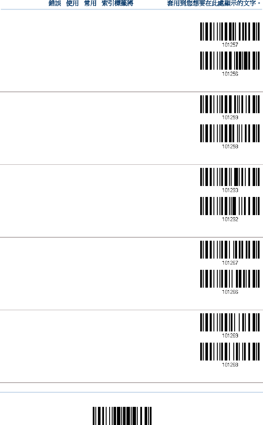
171
Update
Chapter 5
!
! !
!
[
[[
[
]
] ]
]
Heading 1
Heading 1 Heading 1
Heading 1
*Apply
Do Not Apply
Character Substitution
Character SubstitutionCharacter Substitution
Character Substitution
for
for for
for GS1
GS1GS1
GS1-
--
-128
128128
128
*Apply
Do Not Apply
Character Substitution
Character SubstitutionCharacter Substitution
Character Substitution
for
for for
for ISBT 128
ISBT 128ISBT 128
ISBT 128
*Apply
Do Not Apply
Character Substitution
Character SubstitutionCharacter Substitution
Character Substitution
fo
fofo
for
r r
r EAN
EANEAN
EAN-
--
-8 (No Addon)
8 (No Addon)8 (No Addon)
8 (No Addon)
*Apply
Do Not Apply
Character Substitution
Character SubstitutionCharacter Substitution
Character Substitution
for
for for
for EAN
EANEAN
EAN-
--
-8 Addon 2
8 Addon 28 Addon 2
8 Addon 2
*Apply
Do Not Apply
Character Substitution
Character SubstitutionCharacter Substitution
Character Substitution
for
for for
for EAN
EANEAN
EAN-
--
-8 Addon 5
8 Addon 58 Addon 5
8 Addon 5
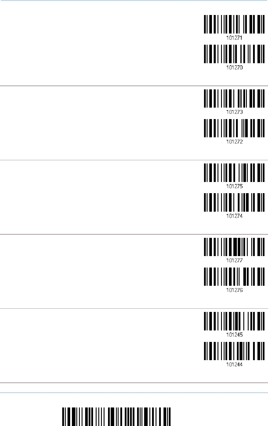
172
Enter Setup
1560/1562 Series Barcode Scanner
User Guide
*Apply
Do Not Apply
Character Substitution
Character SubstitutionCharacter Substitution
Character Substitution
for
for for
for EAN
EANEAN
EAN-
--
-13 (No Addon
13 (No Addon13 (No Addon
13 (No Addon)
))
)
*Apply
Do Not Apply
Character Substitution
Character SubstitutionCharacter Substitution
Character Substitution
for
for for
for EAN
EANEAN
EAN-
--
-13 Addon 2
13 Addon 213 Addon 2
13 Addon 2
*Apply
Do Not Apply
Character Substitution
Character SubstitutionCharacter Substitution
Character Substitution
for
for for
for EAN
EANEAN
EAN-
--
-13 Addon 5
13 Addon 513 Addon 5
13 Addon 5
*Apply
Do Not Apply
Character Substitution
Character SubstitutionCharacter Substitution
Character Substitution
for
for for
for French Pharmacode
French PharmacodeFrench Pharmacode
French Pharmacode
*Apply
Do Not Apply
Charac
CharacCharac
Character Substitution
ter Substitutionter Substitution
ter Substitution
for
for for
for Italian Pharmacode
Italian PharmacodeItalian Pharmacode
Italian Pharmacode
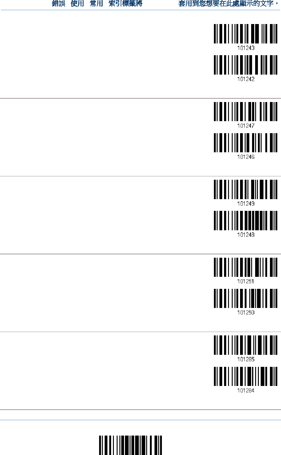
173
Update
Chapter 5
!
! !
!
[
[[
[
]
] ]
]
Heading 1
Heading 1 Heading 1
Heading 1
*Apply
Do Not Apply
Character Substitution
Character SubstitutionCharacter Substitution
Character Substitution
for
for for
for Industrial 25
Industrial 25Industrial 25
Industrial 25
*Apply
Do Not Apply
Character Substitution
Character SubstitutionCharacter Substitution
Character Substitution
for
for for
for Interleaved 25
Interleaved 25Interleaved 25
Interleaved 25
*Apply
Do Not Apply
Character Substitution
Character SubstitutionCharacter Substitution
Character Substitution
for
for for
for Matrix
Matrix Matrix
Matrix 25
2525
25
*Apply
Do Not Apply
Character Substitution
Character SubstitutionCharacter Substitution
Character Substitution
for
for for
for MSI
MSIMSI
MSI
*Apply
Do Not Apply
Character Substitution
Character SubstitutionCharacter Substitution
Character Substitution
for
for for
for Plessey
PlesseyPlessey
Plessey
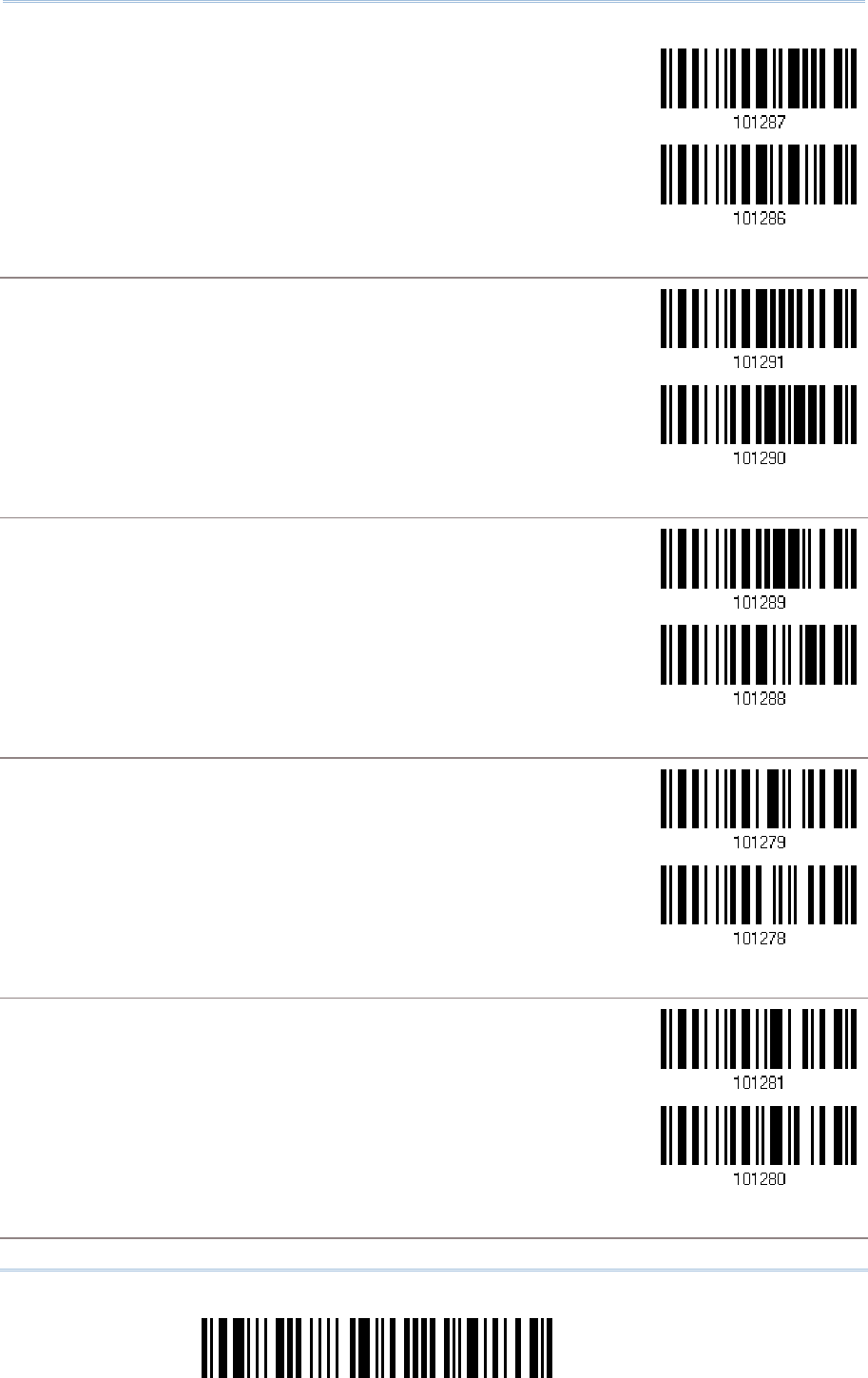
174
Enter Setup
1560/1562 Series Barcode Scanner
User Guide
*Apply
Do Not Apply
Character Substitution
Character SubstitutionCharacter Substitution
Character Substitution
for
for for
for GS1 DataBar
GS1 DataBarGS1 DataBar
GS1 DataBar
*Apply
Do Not Apply
Character Substi
Character SubstiCharacter Substi
Character Substitution
tutiontution
tution
for
for for
for Telepen
TelepenTelepen
Telepen
*Apply
Do Not Apply
Character Substitution
Character SubstitutionCharacter Substitution
Character Substitution
for
for for
for UPC
UPCUPC
UPC-
--
-A
A A
A (No Addon
(No Addon(No Addon
(No Addon)
))
)
*Apply
Do Not Apply
Character Substitution
Character SubstitutionCharacter Substitution
Character Substitution
for
for for
for UPC
UPCUPC
UPC-
--
-A Addon 2
A Addon 2A Addon 2
A Addon 2
*Apply
Do Not Apply
Character Substitution
Character SubstitutionCharacter Substitution
Character Substitution
for
for for
for UPC
UPCUPC
UPC-
--
-A Addon 5
A Addon 5A Addon 5
A Addon 5
175
Update
Chapter 5
!
! !
!
[
[[
[
]
] ]
]
Heading 1
Heading 1 Heading 1
Heading 1
*Apply
Do Not Apply
Character Substitution
Character SubstitutionCharacter Substitution
Character Substitution
for
for for
for UPC
UPCUPC
UPC-
--
-E
E E
E (No Addon
(No Addon(No Addon
(No Addon)
))
)
*Apply
Do Not Apply
Character Substitution
Character SubstitutionCharacter Substitution
Character Substitution
for
for for
for UPC
UPCUPC
UPC-
--
-E Addon 2
E Addon 2E Addon 2
E Addon 2
*Apply
Do Not Apply
Character Substitution
Character SubstitutionCharacter Substitution
Character Substitution
for
for for
for UPC
UPCUPC
UPC-
--
-E Addon 5
E Addon 5E Addon 5
E Addon 5
*Apply
Do Not Apply
Character
Character Character
Character Substitution
SubstitutionSubstitution
Substitution
for Code 11
for Code 11for Code 11
for Code 11
*Apply
Do Not Apply
176
Enter Setup
1560/1562 Series Barcode Scanner
User Guide
5.3 PREFIX/SUFFIX CO
5.3 PREFIX/SUFFIX CO5.3 PREFIX/SUFFIX CO
5.3 PREFIX/SUFFIX CODE
DEDE
DE
By default, there is no prefix code, and [ENTER] or [CR] (Carriage Return) is configured
to be suffix code. Up to 8 characters can be configured, for example, “Barcode_”, and
you will have the string appear in front of the barcode read, like this –
“Barcode_1234567890”.
If “BT HID”, “USB HID” or “Keyboard Wedge” is configured for interface, Key Type
and Key Status will then become applicable. You may decide whether or not to apply
Key Status when “Normal Key” is selected for Key Type.
Key Type
Key TypeKey Type
Key Type
Key Status
Key StatusKey Status
Key Status
Scan Code Up to 4 scan code values are
allowed.
N/A
Normal Key
Up to 8 character strings are
allowed.
Add Shift
Add Left Ctrl
Add Left Alt
Add Right Ctrl
Add Right Alt
Refer to Keyboard Wedge Table.
Configure Prefix
Configure Suffix
1) Read the barcode above to apply prefix code or suffix code separately, and follow
steps 2~3. (Max. 8 characters each)
2) Read the “Hexadecimal Value” barcode on page 242 for the desired character string.
For example, read “2” and “B” for the scanner to prefix or suffix the character [+].
3) Read the “Validate” barcode to complete this setting.
177
Update
Chapter 5
!
! !
!
[
[[
[
]
] ]
]
Heading 1
Heading 1 Heading 1
Heading 1
5.4 CODE ID
5.4 CODE ID5.4 CODE ID
5.4 CODE ID
Up to two characters for Code ID can be configured for each symbology. To make the
Code ID configuration easier, the scanner provides five pre-defined Code ID sets that you
can select one and make necessary changes on it.
If “BT HID”, “USB HID” or “Keyboard Wedge” is configured for interface, Key Type
and Key Status will then become applicable. You may decide whether or not to apply
Key Status when “Normal Key” is selected for Key Type.
Key Type
Key TypeKey Type
Key Type
Key Status
Key StatusKey Status
Key Status
Scan Code Only 1 scan code value is allowed. N/A
Normal Key
Up to 2 character strings are
allowed.
Add Shift
Add Left Ctrl
Add Left Alt
Add Right Ctrl
Add Right Alt
Refer to Keyboard Wedge Table.
Note: "]C1" is the Code ID of GS1-128 (EAN-128) barcodes; "]e0" is the default Code ID
of GS1 DataBar (RSS) barcodes.
5.4.
5.4.5.4.
5.4.1
11
1
SELECT PRE
SELECT PRESELECT PRE
SELECT PRE-
--
-DEFINED CODE ID
DEFINED CODE IDDEFINED CODE ID
DEFINED CODE ID
Apply Code ID Set 1
Apply Code ID Set 2
Apply Code ID Set 3
Apply Code ID Set 4
Apply Code ID Set 5
178
Enter Setup
1560/1562 Series Barcode Scanner
User Guide
Code ID options
Code ID optionsCode ID options
Code ID options
Set 1
Set 1Set 1
Set 1
Set 2
Set 2Set 2
Set 2
Set 3
Set 3Set 3
Set 3
Set 4
Set 4Set 4
Set 4
Set 5
Set 5Set 5
Set 5
Code 39 A C Y M A
Trioptic Code 39 A C Y M X
Italian Pharmacode
A C Y M A
French Pharmacode
A C Y M A
Industrial 25 C H H H S
Interleaved 25 D I Z I S
Matrix 25 E G G G S
Codabar F N X N F
Code 93 I L L L G
Code 128 H K K K C
ISBT 128 H K K K C
UPC-E S E C E E
EAN-8 P B B FF E
EAN-13 M A A F E
UPC-A J A A A E
MSI V V D P M
Plessey W W E Q P
Telepen Z --- --- --- ---
Code 11 K J J D H
Besides Set 1 ~ 5 of Code ID options, you can also scan the barcode below to apply AIM
Code ID as the Code ID option.
Apply AIM Code ID
After applying AIM Code ID, three characters are added in front of the output data. “]” is
always the first character. The second (Character) and third (Modifier Character) may
vary depending on symbologies. Please refer to the table below.
Symbology
SymbologySymbology
Symbology
Character
CharacterCharacter
Character
Modifier Character
Modifier CharacterModifier Character
Modifier Character
Codabar F 0: Standard Codabar symbol. No special processing.
Code 11 H 0: Single modulo 11 check character validated and transmitted
1: Two modulo 11 check characters validated and transmitted
3: Check characters validated but not transmitted
179
Update
Chapter 5
!
! !
!
[
[[
[
]
] ]
]
Heading 1
Heading 1 Heading 1
Heading 1
Code 39 A 0: No check character validation no
r full ASCII processing. All data
transmitted as decoded.
1: Modulo 43 check character validated and transmitted
3: Modulo 43 check character validated but not transmitted
4: Full ASCII character conversion performed. No check character
validation.
5: Full
ASCII character conversion performed. Modulo 43 check
character validated and transmitted.
7: Full ASCII character conversion performed. Modulo 43 check
character validated but not transmitted.
Code 93 G No options specified. Always transmit 0.
Code 128 C
0: Standard data packet. No FNC1 in first or second symbol character
position after start character.
1: EAN/UCC-
128 data packet. FNC1 in first symbol character position
after start character.
2: FNC1 in second symbol character position after start character.
4: Concatenation according to International Society for Blood
Transfusion specifications has been performed. Concatenated data
follows.
GS1 DataBar
Family
e
No option specified at this time. Always transmit 0. GS1 DataBar and
GS1 DataBar Limited transmit with an Application Identifier “01”.
Interleaved
25
I 0: No check character validation
1: Modulo 10 symbol check character validated and transmitted
3: Modulo 10 symbol check character validated but not transmitted
MSI M 0: Modulo 10 symbol check character validated and transmitted
1: Modulo 10 symbol check character validated but not transmitted
Matrix 25 X No options specified. Always transmit 0.
Plessey P No options specified. Always transmit 0.
Industrial 25 S No options specified. Always transmit 0.
Telepen B No options specified. Always transmit 0.
UPC/EAN E 0: Standard data packet in full EAN format (13 digits for EAN-
13,
UPC-A, and UPC-E; does not include add-on data)
3: Combined data packet comprising 13 digits from EAN-13, UPC-
A, or
UPC-E symbol and 2 or 5 digits from add-on symbol
4: EAN-8 data packet
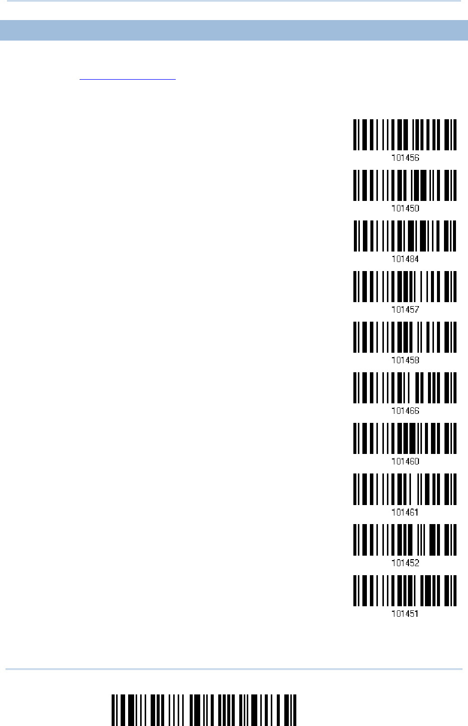
180
Enter Setup
1560/1562 Series Barcode Scanner
User Guide
5.4.2
5.4.25.4.2
5.4.2
CHANGE CODE ID
CHANGE CODE IDCHANGE CODE ID
CHANGE CODE ID
1) Read the barcode below to change code ID of a specific symbology.
2) Read the “Hexadecimal Value” barcode on page 242 for the desired character string.
For example, read “4” and “4” for applying the character [D] for Code ID.
3) Read the “Validate” barcode to complete this setting.
Configure Code ID for
Codabar
Configure Code ID for
Code 39
Configure Code ID for
Trioptic Code 39
Configure Code ID for
Code 93
Configure Code ID for
Code 128
Configure Code ID for
ISBT 128
Configure Code ID for
EAN-8
Configure Code ID for
EAN-13
Configure Code ID for
French Pharmacode
Configure Code ID for
Italian Pharmacode
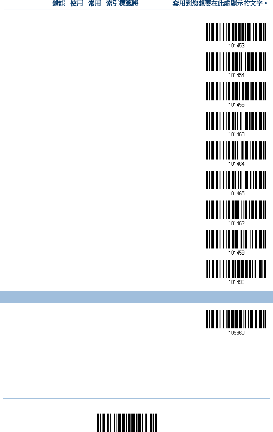
181
Update
Chapter 5
!
! !
!
[
[[
[
]
] ]
]
Heading 1
Heading 1 Heading 1
Heading 1
Configure Code ID for
Industrial 25
Configure Code ID for
Interleaved 25
Configure Code ID for
Matrix 25
Configure Code ID for
MSI
Configure Code ID for
Plessey
Configure Code ID for
Telepen
Configure Code ID for
UPC-A
Configure Code ID for
UPC-E
Configure Code ID for
Code 11
5.4.3 CLEAR CODE ID
5.4.3 CLEAR CODE ID 5.4.3 CLEAR CODE ID
5.4.3 CLEAR CODE ID SETTINGS
SETTINGSSETTINGS
SETTINGS
Clear All Code ID
Settings
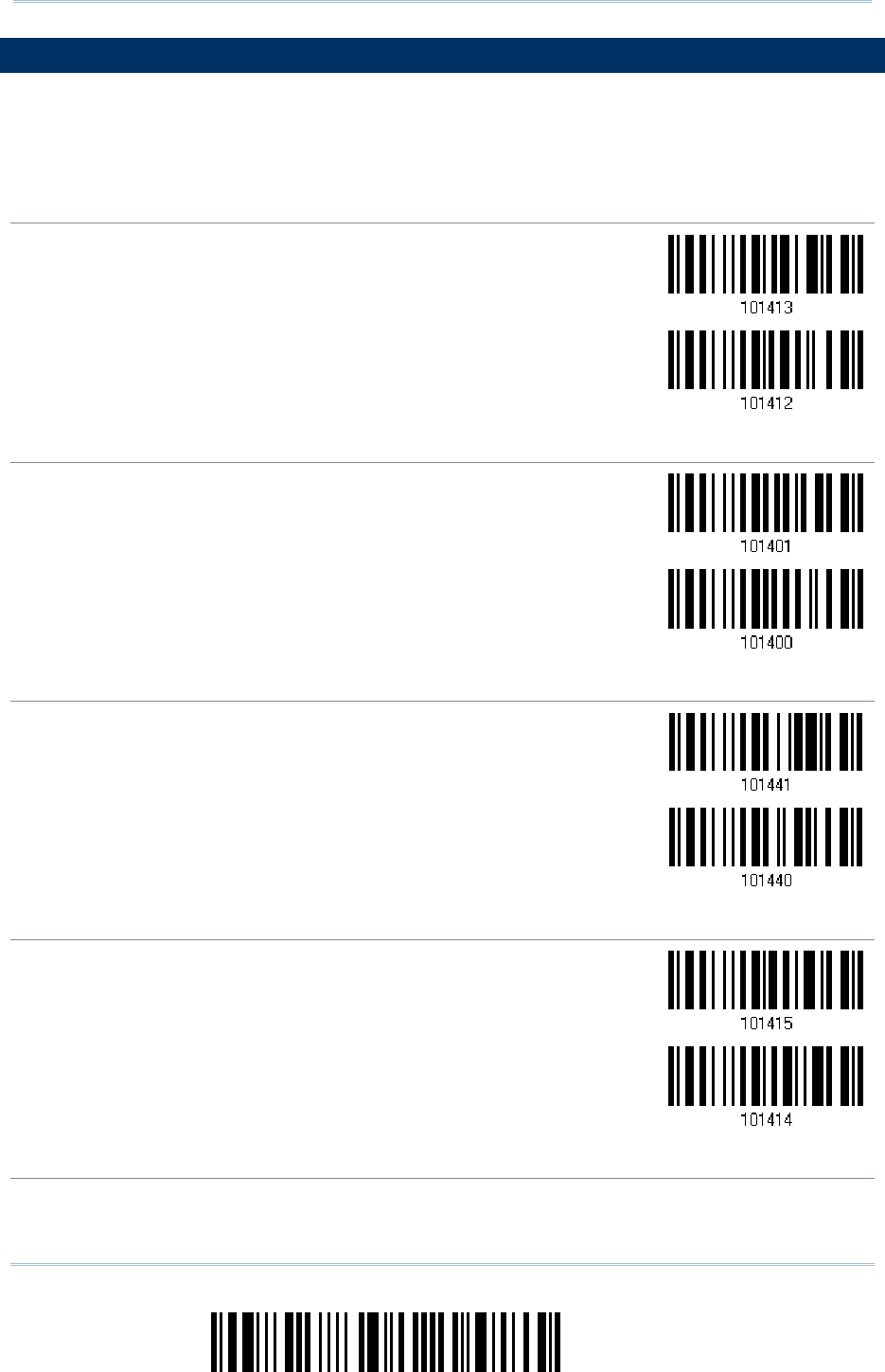
182
Enter Setup
1560/1562 Series Barcode Scanner
User Guide
5.5 LENGTH CODE
5.5 LENGTH CODE5.5 LENGTH CODE
5.5 LENGTH CODE
A two-digit code representing the length of barcode data (character count) can be
inserted in front of data being transmitted. Such "Length" code can be individually
enabled or disabled for each symbology.
Length Code
Length CodeLength Code
Length Code
for
for for
for Codabar
CodabarCodabar
Codabar
Apply
*Do Not Apply
Length Code
Length CodeLength Code
Length Code
for
for for
for Cod
CodCod
Code 39
e 39e 39
e 39
Apply
*Do Not Apply
Length Code
Length CodeLength Code
Length Code
for Trioptic
for Trioptic for Trioptic
for Trioptic Code 39
Code 39Code 39
Code 39
Apply
*Do Not Apply
Length Code
Length CodeLength Code
Length Code
for
for for
for Code 93
Code 93Code 93
Code 93
Apply
*Do Not Apply
Length Code
Length CodeLength Code
Length Code
for
for for
for Code 128
Code 128Code 128
Code 128
183
Update
Chapter 5
!
! !
!
[
[[
[
]
] ]
]
Heading 1
Heading 1 Heading 1
Heading 1
Apply
*Do Not Apply
Length Code
Length CodeLength Code
Length Code
for
for for
for GS1
GS1GS1
GS1-
--
-128
128 128
128 & GS1 DataBa
& GS1 DataBa& GS1 DataBa
& GS1 DataBar
rr
r
Apply
*Do Not Apply
Length Code
Length CodeLength Code
Length Code
for
for for
for ISBT 128
ISBT 128ISBT 128
ISBT 128
Apply
*Do Not Apply
Length Code
Length CodeLength Code
Length Code
for
for for
for EAN
EANEAN
EAN-
--
-8
88
8
Apply
*Do Not Apply
Length Code
Length CodeLength Code
Length Code
for
for for
for EAN
EANEAN
EAN-
--
-13
1313
13
Apply
*Do Not Apply
184
Enter Setup
1560/1562 Series Barcode Scanner
User Guide
Length Code
Length CodeLength Code
Length Code
for
for for
for French Pharmacode
French PharmacodeFrench Pharmacode
French Pharmacode
Apply
*Do Not Apply
Length Code
Length CodeLength Code
Length Code
for
for for
for Italian Pharmacode
Italian PharmacodeItalian Pharmacode
Italian Pharmacode
Apply
*Do Not Apply
Length Code
Length CodeLength Code
Length Code
for
for for
for Industrial 25
Industrial 25Industrial 25
Industrial 25
Apply
*Do Not Apply
Length Code
Length CodeLength Code
Length Code
for
for for
for Interleaved 25
Interleaved 25Interleaved 25
Interleaved 25
Apply
*Do Not Apply
Length Code
Length CodeLength Code
Length Code
for
for for
for Matrix 25
Matrix 25Matrix 25
Matrix 25
Apply
*Do Not Apply
185
Update
Cha
pter 5
!
! !
!
[
[[
[
]
] ]
]
Heading 1
Heading 1 Heading 1
Heading 1
Length Code
Length CodeLength Code
Length Code
for
for for
for MSI
MSIMSI
MSI
Apply
*Do Not Apply
Length Code
Length CodeLength Code
Length Code
for
for for
for Plessey
PlesseyPlessey
Plessey
Apply
*Do Not Apply
Length Code
Length CodeLength Code
Length Code
for
for for
for Telepen
TelepenTelepen
Telepen
Apply
*Do Not Apply
Length Code
Length CodeLength Code
Length Code
for
for for
for UPC
UPCUPC
UPC-
--
-A
AA
A
Apply
*Do Not Apply
Length Code
Length CodeLength Code
Length Code
for
for for
for UPC
UPCUPC
UPC-
--
-E
EE
E
Apply
*Do Not Apply
186
Enter Setup
1560/1562 Series Barcode Scanner
User Guide
Length Code
Length CodeLength Code
Length Code
for Code 11
for Code 11for Code 11
for Code 11
Apply
*Do Not Apply
5.6 MULTI
5.6 MULTI5.6 MULTI
5.6 MULTI-
--
-BARCODE EDITOR
BARCODE EDITORBARCODE EDITOR
BARCODE EDITOR
The Multi-Barcode Editor allows you to decide the output sequence of a concatenation of
barcodes. Up to five barcodes can be specified. When you enable this mode, it will force
the scanner to apply Laser mode as the scan mode.
Note: The Multi-Barcode Editor has nothing to do with Multi-Barcode Mode.
The barcodes that are found meeting the specified criteria below will be arranged in the
desired sequence.
Code Type
4-digit barcode length, excluding prefix, suffix, length code, etc.
Matching the first character of barcode data
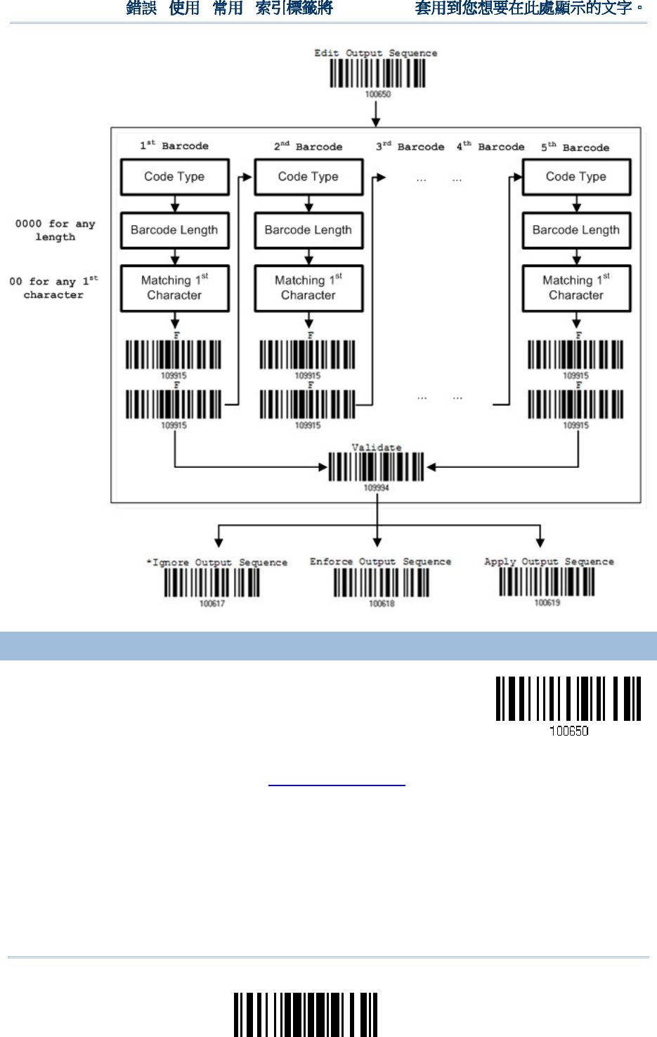
187
Update
Chapter 5
!
! !
!
[
[[
[
]
] ]
]
Heading 1
Heading 1 Heading 1
Heading 1
5.6.1 EDIT A CONCATE
5.6.1 EDIT A CONCATE5.6.1 EDIT A CONCATE
5.6.1 EDIT A CONCATENATION OF BARCODES
NATION OF BARCODESNATION OF BARCODES
NATION OF BARCODES
Edit Output Sequence
1) Read the barcode above to start editing a concatenation of barcodes.
2) Code Type setting – read the “Hexadecimal Value” barcode on page 242 for Code
Type of the (first) barcode. For example, read “4” and “1” for Code 39.
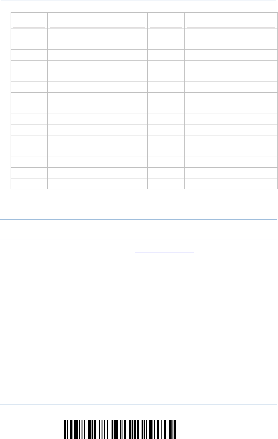
188
Enter Setup
1560/1562 Series Barcode Scanner
User Guide
Code Type
Code TypeCode Type
Code Type
Symbology
SymbologySymbology
Symbology
Code Type
Code TypeCode Type
Code Type
Symbology
SymbologySymbology
Symbology
40 (@) ISBT 128 4F (O) EAN-8 with Addon 5
41 (A) Code 39 50 (P) EAN-13
42 (B) Italian Pharmacode 51 (Q) EAN-13 with Addon 2
43 (C) French Pharmacode 52 (R) EAN-13 with Addon 5
44 (D) Industrial 25 53 (S) MSI
45 (E) Interleaved 25 54 (T) Plessey
46 (F) Matrix 25 55 (U) GS1-128 (EAN-128)
47 (G) Codabar (NW7) 56 (V) UPC-A
48 (H) Code 93 57 (W) UPC-A with Addon 2
49 (I) Code 128 58 (X) UPC-A with Addon 5
4A (J) UPC-E0 / UPC-E1
4B (K) UPC-E with Addon 2 5A (Z) Telepen
4C (L) UPC-E with Addon 5 5B ( [ ) GS1 DataBar (RSS)
4D (M) EAN-8
4E (N) EAN-8 with Addon 2
3) Barcode Length setting – read the “Decimal Value” barcode on page 241 for the
4-digit length of the (first) barcode. For example, read “0065” for barcode length of
65 characters or read “0000” for any length.
Note: If not reading 0000 for any length, the 4-digit length must exclude prefix, suffix
(0x0d by default), length code, etc.
4) Matching Character setting – read the “Hexadecimal Value” barcode on page 242 for
the 1
st
character that must be found matching in the (first) barcode. For example,
read “4” and “1” for matching character “A” as the first character in the barcode or
read “00” for any character.
5) Read twice the “F” barcode on page 242 (“FF”) to complete the setting of each
barcode.
6) Read the “Validate” barcode to end the editing of the barcode set.
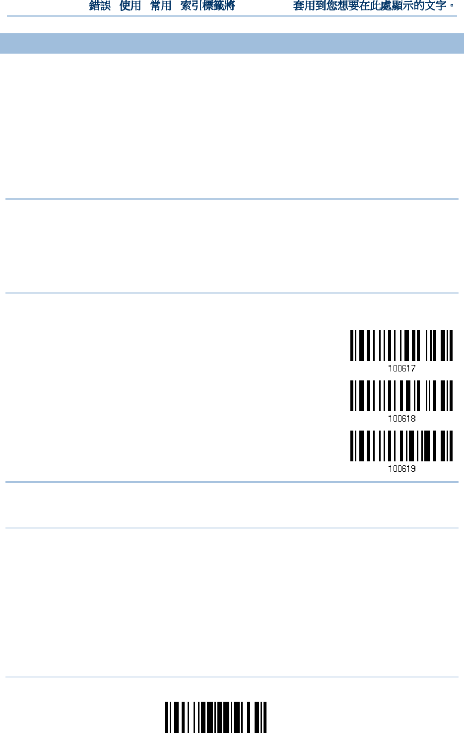
189
Update
Chapter 5
!
! !
!
[
[[
[
]
] ]
]
Heading 1
Heading 1 Heading 1
Heading 1
5.6.2 ACTIVATE THE C
5.6.2 ACTIVATE THE C5.6.2 ACTIVATE THE C
5.6.2 ACTIVATE THE CONCATENATION OF BARC
ONCATENATION OF BARCONCATENATION OF BARC
ONCATENATION OF BARCODES
ODESODES
ODES
By default, the output sequence editing of the concatenation of barcodes is not applied.
When “Enforce Output Sequence” is enabled, all barcodes read by the scanner must meet
with the criteria for the concatenation. If data is found excluded from all output sequence
sets (= not meeting with the criteria), the scanner will not accept the reading, and
therefore, data will not be transmitted.
When “Apply Output Sequence” is enabled, only barcodes found meeting with the criteria
are counted for the concatenation. Those found not meeting with the criteria are
processed normally and individually.
Note: When it requires reading more barcodes to complete the “output sequence”
requirements, the scanner will respond with one short beep (low tone). After
reading an acceptable barcode, its LED indicator will become solid green and go off
quickly (= Good Read).
Upon completion of reading acceptable barcodes, the scanner will respond with
one short beep (high tone) and its LED indicator will become solid green and go off
quickly (= Good Read).
*Ignore Output
Sequence
Enforce Output
Sequence
Apply Output
Sequence
Warning: When you disable the Multi-Barcode Editor later, the scan mode remains
unchanged. If Laser mode is not desired, proceed to select a scan mode
best suits your application.

190
Enter Setup
1560/1562 Series Barcode Scanner
User Guide
5.7
5.75.7
5.7
REMOV
REMOVREMOV
REMOVAL OF SPECIAL CHARAC
AL OF SPECIAL CHARACAL OF SPECIAL CHARAC
AL OF SPECIAL CHARACTER
TERTER
TER
You can only specify 1 character, but it will remove every matching character
encountered from the starting position of barcode data until a different character is met.
For example, if it is configured to remove the character “0” (hex value is “30”), one or
more zeros will be stripped off the barcode data “012345” and “00012345”. However, for
barcode data “010333”, only the first zero will be stripped off.
Remove Special
Character
1) Read the barcode above to remove the specified character.
2) Read the “Hexadecimal Value” barcode on page 242 for the desired character.
For example, read “3” and “0” for the scanner to remove the character “0”.
3) Read the “Validate” barcode to complete this setting.

191
Update
The scanner allows advanced data editing by applying user-configured editing formats.
The whole processed data can be divided into fields by user-specified rules. These fields
together with the user-configurable additional fields consist of the data actually sent to
the host computer.
[Prefix Code]
[Code ID] [Length Code]
[Data] [Suffix Code]
Additional
Field(s)
None
by default
None
by default
None
by default
Barcode itself 0x0d
by default
IN THIS CHAPTER
IN THIS CHAPTERIN THIS CHAPTER
IN THIS CHAPTER
6.1 Activating Editing Formats ......................................... 192
6.2 How to Configure Editing Formats ............................... 194
6.3 Configuring Format — Define Data Criteria ................... 197
6.4 Configuring Format — Define Data Field ....................... 205
6.5 Configuring Format — Define Transmission Sequence .... 214
6.6 Programming Examples ............................................. 216
Chapter
Chapter Chapter
Chapter
6
66
6
APPLYING FORMATS FOR
APPLYING FORMATS FORAPPLYING FORMATS FOR
APPLYING FORMATS FOR
DA
DADA
DATA EDITING
TA EDITINGTA EDITING
TA EDITING
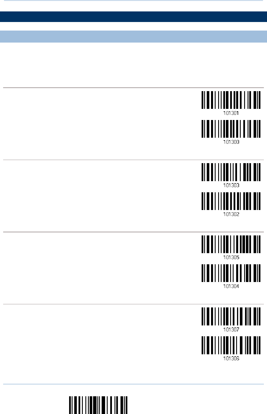
192
End Programming Format
1560/1562 Series Barcode Scanner
User Guide
6.
6.6.
6.1
1 1
1 ACTIVATING EDITING F
ACTIVATING EDITING FACTIVATING EDITING F
ACTIVATING EDITING FORMATS
ORMATSORMATS
ORMATS
6.1.1 ACTIVATE EDITI
6.1.1 ACTIVATE EDITI6.1.1 ACTIVATE EDITI
6.1.1 ACTIVATE EDITING FORMATS
NG FORMATSNG FORMATS
NG FORMATS
If you have already configured any editing format before, you may directly apply the
editing format. If not, you must start with configuring an editing format first, and then,
activate the editing format when it is desired in use.
Editing Format 1
Editing Format 1Editing Format 1
Editing Format 1
Enable
*Disable
Editing Format 2
Editing Format 2Editing Format 2
Editing Format 2
Enable
*Disable
Editing Format 3
Editing Format 3Editing Format 3
Editing Format 3
Enable
*Disable
Editing Format 4
Editing Format 4Editing Format 4
Editing Format 4
Enable
*Disable
193
Update
Chapter 6
!
! !
!
[
[[
[
]
] ]
]
Heading 1
Heading 1 Heading 1
Heading 1
Editing Format 5
Editing Format 5Editing Format 5
Editing Format 5
Enable
*Disable
6.1.2
6.1.2 6.1.2
6.1.2 EXCLUSIVE DATA EDITI
EXCLUSIVE DATA EDITIEXCLUSIVE DATA EDITI
EXCLUSIVE DATA EDITING
NGNG
NG
By default, only barcodes found meeting with the criteria are processed by the editing
formats. Those found not meeting with the criteria are processed normally.
When “Exclusive Data Editing” is enabled, all barcodes read by the scanner must be
processed by the editing formats. If data is found excluded from all enabled editing
formats (= not meeting with the specified criteria), the scanner will not accept the
reading, and therefore, data will not be transmitted.
Yes
*No
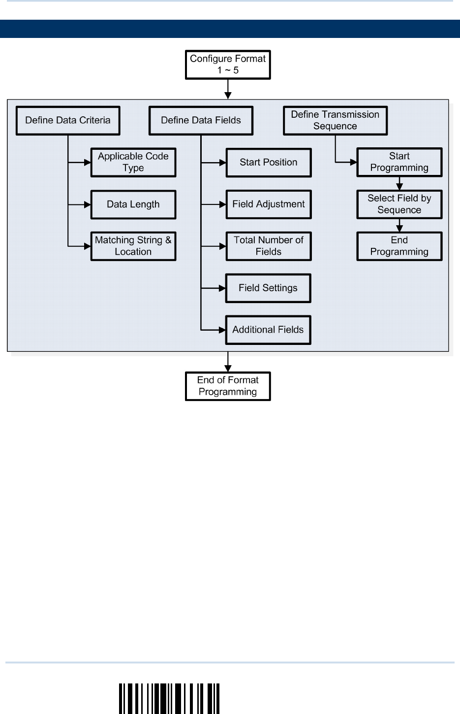
194
End Programming Format
1560/1562 Series Barcode Scanner
User Guide
6.
6.6.
6.2
2 2
2 HOW TO CONFIGURE
HOW TO CONFIGURE HOW TO CONFIGURE
HOW TO CONFIGURE EDITING FORMAT
EDITING FORMATEDITING FORMAT
EDITING FORMATS
SS
S
195
Update
Chapter 6
!
! !
!
[
[[
[
]
] ]
]
Heading 1
Heading 1 Heading 1
Heading 1
6.2.1 SELECT FORMAT
6.2.1 SELECT FORMAT 6.2.1 SELECT FORMAT
6.2.1 SELECT FORMAT TO CONFIGURE
TO CONFIGURETO CONFIGURE
TO CONFIGURE
Start Programming Format
Start Programming FormatStart Programming Format
Start Programming Format
Select one editing format (Format 1~5) and the parameters pertaining to the editing format can
then be configured – applicable code type, data length, matching string & location, start position,
field adjustment, total number of fields, field settings (field-dividing rule), additional fields, and
field transmission sequence.
Up to five different formats can be specified.
Configure Format 1
Configure Format 2
Configure Format 3
Configure Format 4
Configure Format 5
Note: Before you complete the programming of an editing format, if you have the
scanner read any barcode for parameters other than those pertaining to the
editing format, it will automatically abort the programming process.
End Programming Format
End Programming FormatEnd Programming Format
End Programming Format
After having configured all the desired parameters, you must have the scanner read the “End
Programming Format” barcode, which can be located at the bottom of every even page in this
chapter.
End Programming
Format
196
End Programming Format
1560/1562 Series Barcode Scanner
User Guide
6.2.2
6.2.2 6.2.2
6.2.2 RESTORE DEFAULT FORM
RESTORE DEFAULT FORMRESTORE DEFAULT FORM
RESTORE DEFAULT FORMAT
ATAT
AT
You may select an existing editing format and have the defaults restored. The default
settings of an editing format are listed below.
Editing format
Editing formatEditing format
Editing format
Defaults
DefaultsDefaults
Defaults
Applicable Code Type All
Data Length 0 (No qualification)
Matching String Disable
Matching String Location None
Start Position From head
Field Adjustment No adjustment
Total Number of Fields 1
Field Setting – field-dividing rule Not configured
Additional Fields None
Field Transmission Sequence F1
Restore Default
Format

197
Update
Chapter 6
!
! !
!
[
[[
[
]
] ]
]
Heading 1
Heading 1 Heading 1
Heading 1
6.3 CONFIGURING FORM
6.3 CONFIGURING FORM6.3 CONFIGURING FORM
6.3 CONFIGURING FORMAT
AT AT
AT —
——
—
DEFINE DATA
DEFINE DATADEFINE DATA
DEFINE DATA
CRITERIA
CRITERIACRITERIA
CRITERIA
Three applicable conditions can be configured to check whether the data read by the
scanner can be processed by the particular editing format.
Note: Data editing cannot be performed unless the three conditions are all met.
6.3.1 APPLICABLE COD
6.3.1 APPLICABLE COD6.3.1 APPLICABLE COD
6.3.1 APPLICABLE CODE
E E
E TYPE
TYPETYPE
TYPE
By default, barcodes of all the supported symbologies will be processed by any editing
format, if having been configured and enabled. For quick configuration, you may first
clear all, and then select the desired symbologies.
Note: You must have at least one symbology selected.
*Apply to All
Clear All
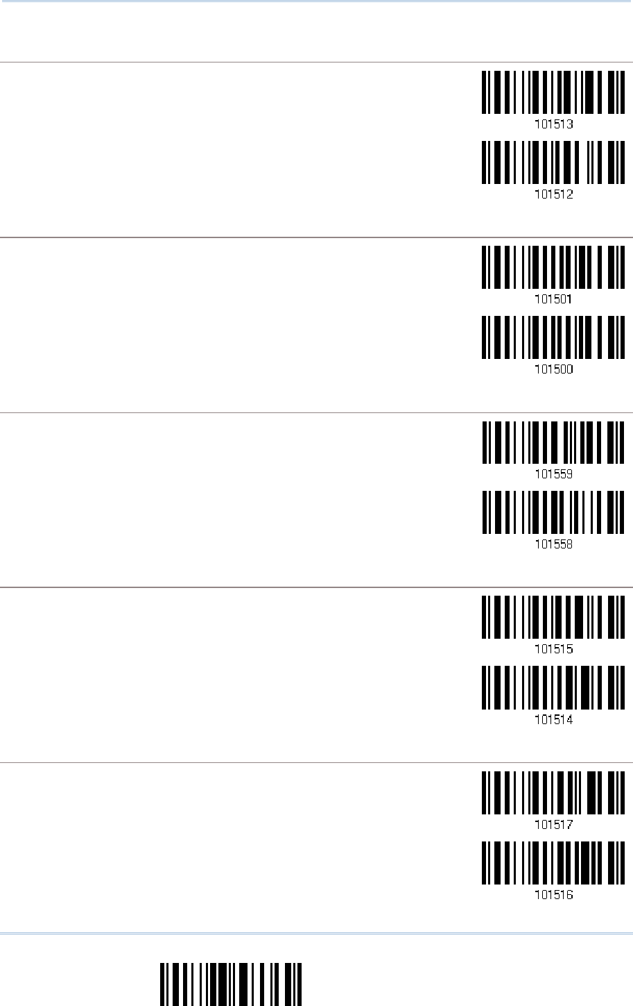
198
End Programming Format
1560/1562 Series Barcode Scanner
User Guide
Editing Format for Codabar
Editing Format for CodabarEditing Format for Codabar
Editing Format for Codabar
*Apply
Do Not Apply
Editing Format for Code 39
Editing Format for Code 39Editing Format for Code 39
Editing Format for Code 39
*Apply
Do Not Apply
Editing Format for
Editing Format for Editing Format for
Editing Format for Trioptic
Trioptic Trioptic
Trioptic Code 39
Code 39Code 39
Code 39
*Apply
Do Not Apply
Edi
EdiEdi
Editing Format for Code 93
ting Format for Code 93ting Format for Code 93
ting Format for Code 93
*Apply
Do Not Apply
Editing Format for Code 128
Editing Format for Code 128Editing Format for Code 128
Editing Format for Code 128
*Apply
Do Not Apply
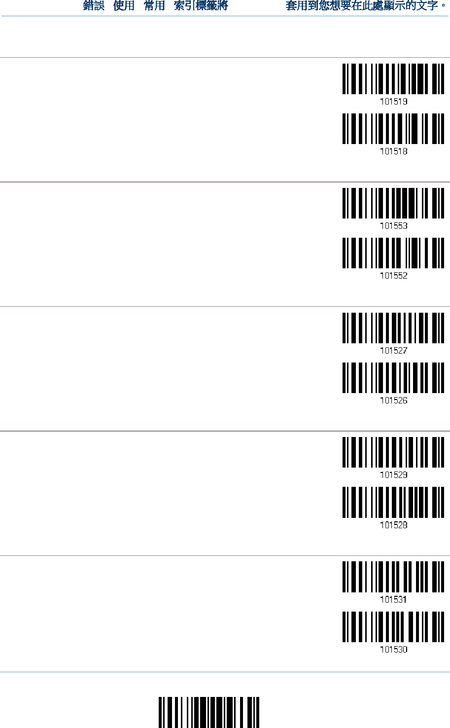
199
Update
Chapter 6
!
! !
!
[
[[
[
]
] ]
]
Heading 1
Heading 1 Heading 1
Heading 1
Editing Format for
Editing Format for Editing Format for
Editing Format for GS1
GS1GS1
GS1-
--
-128
128 128
128 & GS1 DataBar
& GS1 DataBar& GS1 DataBar
& GS1 DataBar
*Apply
Do Not Apply
Editing Format for
Editing Format for Editing Format for
Editing Format for ISBT 128
ISBT 128ISBT 128
ISBT 128
*Apply
Do Not Apply
Edi
EdiEdi
Editing Format for EAN
ting Format for EANting Format for EAN
ting Format for EAN-
--
-8
88
8
*Apply
Do Not Apply
Editing Format for EAN
Editing Format for EANEditing Format for EAN
Editing Format for EAN-
--
-8 Addon 2
8 Addon 28 Addon 2
8 Addon 2
*Apply
Do Not Apply
Editing Format for EAN
Editing Format for EANEditing Format for EAN
Editing Format for EAN-
--
-8 Addon 5
8 Addon 58 Addon 5
8 Addon 5
*Apply
Do Not Apply
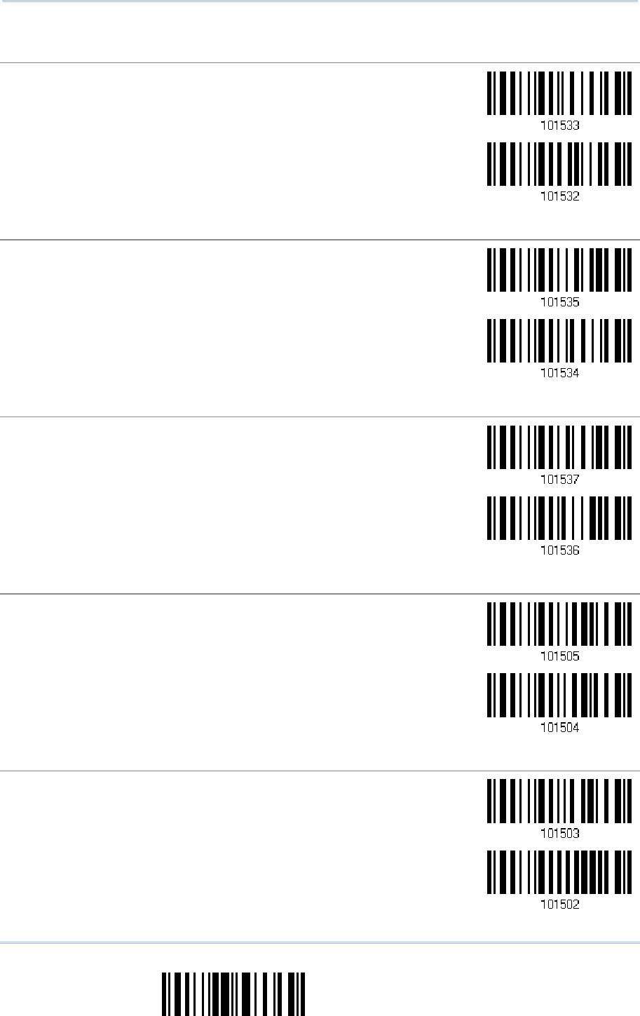
200
End Programming Format
1560/1562 Series Barcode Scanner
User Guide
Editing Format for EAN
Editing Format for EANEditing Format for EAN
Editing Format for EAN-
--
-13
1313
13
*Apply
Do Not Apply
Editing Fo
Editing FoEditing Fo
Editing Format for EAN
rmat for EANrmat for EAN
rmat for EAN-
--
-13 Addon 2
13 Addon 213 Addon 2
13 Addon 2
*Apply
Do Not Apply
Editing Format for EAN
Editing Format for EANEditing Format for EAN
Editing Format for EAN-
--
-13 Addon 5
13 Addon 513 Addon 5
13 Addon 5
*Apply
Do Not Apply
Editing Format for French Pharmacode
Editing Format for French PharmacodeEditing Format for French Pharmacode
Editing Format for French Pharmacode
*Apply
Do Not Apply
Editing Format for Italian Pharmacode
Editing Format for Italian PharmacodeEditing Format for Italian Pharmacode
Editing Format for Italian Pharmacode
*Apply
Do Not Apply
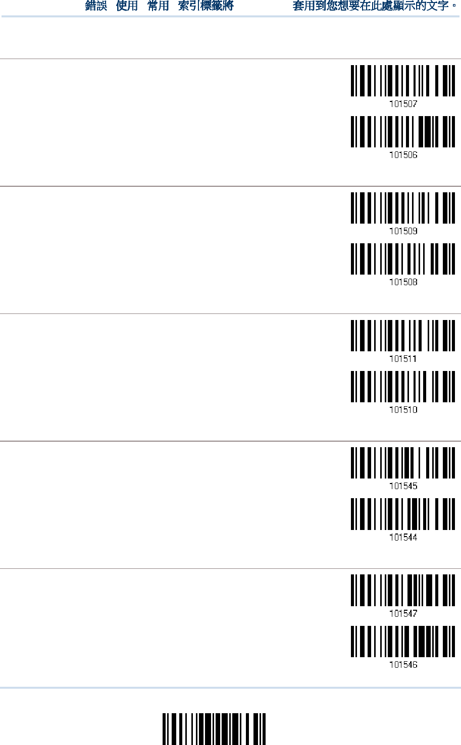
201
Update
Chapter 6
!
! !
!
[
[[
[
]
] ]
]
Heading 1
Heading 1 Heading 1
Heading 1
Editing Format for Industrial 25
Editing Format for Industrial 25Editing Format for Industrial 25
Editing Format for Industrial 25
*Apply
Do Not Apply
Editing Format for Interleaved 25
Editing Format for Interleaved 25Editing Format for Interleaved 25
Editing Format for Interleaved 25
*Apply
Do Not Apply
Editing Format for Matrix 25
Editing Format for Matrix 25Editing Format for Matrix 25
Editing Format for Matrix 25
*Apply
Do Not Apply
Editing Format for MSI
Editing Format for MSIEditing Format for MSI
Editing Format for MSI
*Apply
Do Not Apply
Editing Format for Plessey
Editing Format for PlesseyEditing Format for Plessey
Editing Format for Plessey
*Apply
Do Not Apply
202
End Programming Format
1560/1562 Series Barcode Scanner
User Guide
Editing Format for Telepen
Editing Format for TelepenEditing Format for Telepen
Editing Format for Telepen
*Apply
Do Not Apply
Editing Format for UPC
Editing Format for UPCEditing Format for UPC
Editing Format for UPC-
--
-A
AA
A
*Apply
Do Not Apply
Editing Format for UPC
Editing Format for UPCEditing Format for UPC
Editing Format for UPC-
--
-A Addon 2
A Addon 2A Addon 2
A Addon 2
*Apply
Do Not Apply
Editing
Editing Editing
Editing Format for UPC
Format for UPCFormat for UPC
Format for UPC-
--
-A Addon 5
A Addon 5A Addon 5
A Addon 5
*Apply
Do Not Apply
Editing Format for UPC
Editing Format for UPCEditing Format for UPC
Editing Format for UPC-
--
-E
EE
E
*Apply
Do Not Apply
203
Update
Chapter 6
!
! !
!
[
[[
[
]
] ]
]
Heading 1
Heading 1 Heading 1
Heading 1
Editing Format for UPC
Editing Format for UPCEditing Format for UPC
Editing Format for UPC-
--
-E Addon 2
E Addon 2E Addon 2
E Addon 2
*Apply
Do Not Apply
Editing Format for UPC
Editing Format for UPCEditing Format for UPC
Editing Format for UPC-
--
-E Addon 5
E Addon 5E Addon 5
E Addon 5
*Apply
Do Not Apply
Editing
Editing Editing
Editing Format for
Format for Format for
Format for Code 11
Code 11Code 11
Code 11
*Apply
Do Not Apply
204
End Programming Format
1560/1562 Series Barcode Scanner
User Guide
6.3.2 DATA LENGTH
6.3.2 DATA LENGTH6.3.2 DATA LENGTH
6.3.2 DATA LENGTH
The length must include prefix, suffix (0x0d by default), length code, etc. By default,
barcodes of any length (character count) are eligible for data editing.
You may specify a value from 0 to 254.
When zero is given to both, the scanner will not perform the length qualification.
1) Read the barcode below to specify Max. Length or Min. Length separately, and follow
steps 2~3.
Max. Length
Min. Length
2) Read the “Decimal Value” barcode on page 241 for the desired length.
3) Read the “Validate” barcode on the same page to complete this setting.
205
Update
Chapter 6
!
! !
!
[
[[
[
]
] ]
]
Heading 1
Heading 1 Heading 1
Heading 1
6.3.3 MATCHING STRIN
6.3.3 MATCHING STRIN6.3.3 MATCHING STRIN
6.3.3 MATCHING STRING & LOCATION
G & LOCATIONG & LOCATION
G & LOCATION
By default, no matching string is specified, and therefore, it is disabled. You may enable
this feature by specifying a matching string; up to four characters are allowed.
When the Matching String Location is zero, the scanner will only check for the
existence of the matching string in the barcode data.
You may specify a value from 1 to 254 to indicate where the matching string starts in
the barcode data.
1) Read the barcode to specify a matching string.
Matching String…
2) Read the “Hexadecimal Value” barcode on page 242 for the desired character string.
3) Read the “Validate” barcode to complete this setting.
4) Read the barcode to specify the location of the matching string.
Location of Matching
String…
5) Read the “Decimal Value” barcode on page 241 for the desired location.
6) Read the “Validate” barcode on the same page to complete this setting.
6.4 CONFIGURING FORM
6.4 CONFIGURING FORM6.4 CONFIGURING FORM
6.4 CONFIGURING FORMAT
AT AT
AT —
——
—
DEFINE DA
DEFINE DADEFINE DA
DEFINE DATA
TA TA
TA FIELD
FIELDFIELD
FIELD
6
66
6.
..
.4.1
4.14.1
4.1
START POSITION
START POSITIONSTART POSITION
START POSITION
Data can be divided into fields in one of the following direction –
from head (F1) to tail (F5)
from tail (F1) to head (F5)
*From Head
From Tail
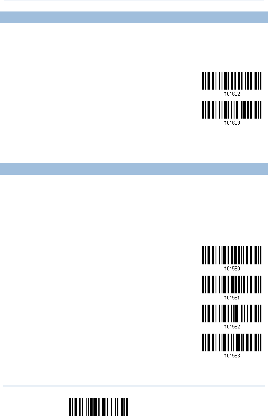
206
End Programming Format
1560/1562 Series Barcode Scanner
User Guide
6
66
6.
..
.4.2 FIELD ADJUSTMENT
4.2 FIELD ADJUSTMENT4.2 FIELD ADJUSTMENT
4.2 FIELD ADJUSTMENT
You may apply equal length to all fields, if necessary. If data is found longer than
specified, it will be truncated automatically. When data is found shorter, it will add
“Space” (0x20) to field.
*No adjustment
Set length to adjust
fields… (*0)
1) Read the barcode above to adjust field by length.
2) Read the “Decimal Value” barcode on page 241 for the desired field length.
3) Read the “Validate” barcode on the same page to complete this setting.
6
66
6.
..
.4.3 TOTAL NUMBER OF
4.3 TOTAL NUMBER OF 4.3 TOTAL NUMBER OF
4.3 TOTAL NUMBER OF FIELDS
FIELDSFIELDS
FIELDS
Data can be divided into at most 6 fields; each of them is numbered from F1 to F6
accordingly. However, only F1~F5 can be configured.
The total number of fields must be specified correctly. If three fields are configured
for the editing format, the data characters after F3 will be assigned to F4
automatically. This feature is quite useful especially when data of variable lengths is
processed by editing formats.
*One Field
Two Fields
Three Fields
Four Fields
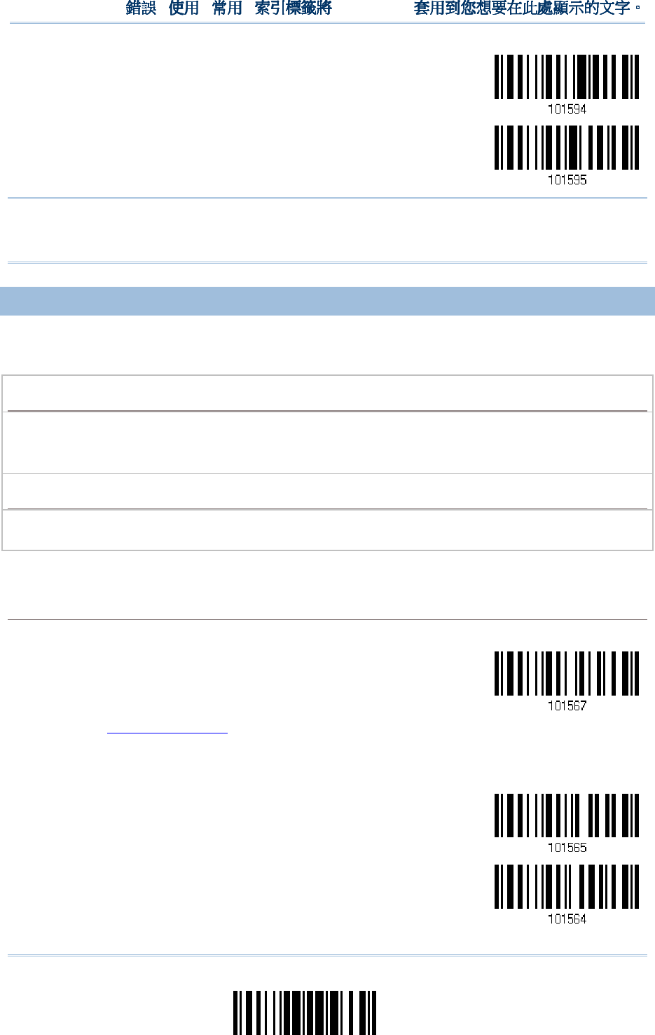
207
Update
Chapter 6
!
! !
!
[
[[
[
]
] ]
]
Hea
HeaHea
Hea
ding 1
ding 1 ding 1
ding 1
Five Fields
Six Fields
Note: The number of configurable fields is always one less than the total number of
fields specified. The extra data characters beyond the last field configured will be
automatically assigned to the next field.
6.
6.6.
6.4.4
4.44.4
4.4
FIELD SETTINGS
FIELD SETTINGSFIELD SETTINGS
FIELD SETTINGS
Data eligible for editing formats is divided into fields by user-specified rules – either
using the field terminating string or specified field length.
By Terminating String
By Terminating StringBy Terminating String
By Terminating String
Specify the field terminating string. Up to two characters are allowed. The scanner will search for
the occurrence of this particular string in the data.
By default, this string will be included in the field. You may discard it.
By Length
By LengthBy Length
By Length
Alternatively, you may simply specify the field length. The scanner will assign the next specified
number of characters into the field.
Field 1
Field 1Field 1
Field 1
Setting
SettingSetting
Setting
1.
Read the barcode below to divide field 1 by a specified terminating string.
Select
Field Separator
to Divide Field 1…
2.
Read the “Hexadecimal Value” barcode on page 242 for the desired character string.
3.
Read the “Validate” barcode to complete this setting.
4.
Read the “Discard Separator” barcode if the field separator is not desired in the field.
*Include Separator
Discard Separator
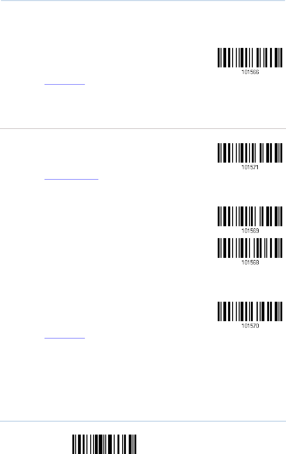
208
End Programming Format
1560/1562 Series Barcode Scanner
User Guide
If not dividing the field by a specific separator, you may divide it by a specified length.
1.
Read the barcode below to divide field 1 by length.
Divide Field 1
by Length
2.
Read the “Decimal Value” barcode on page 241 for the desired field length.
3.
Read the “Validate” barcode on the same page to complete this setting.
Field 2
Field 2Field 2
Field 2
Setting
SettingSetting
Setting
1.
Read the barcode below to divide field 2 by a specified terminating string.
Select
Field Separator
to Divide Field 2…
2.
Read the “Hexadecimal Value” barcode on page 242 for the desired character string.
3.
Read the “Validate” barcode to complete this setting.
4.
Read the “Discard Separator” barcode if the field separator is not desired in the field.
*Include Separator
Discard Separator
If not dividing the field by a specific separator, you may divide it by a specified length.
1.
Read the barcode below to divide field 2 by length.
Divide Field 2
by Length
2.
Read the “Decimal Value” barcode on page 241 for the desired field length.
3.
Read the “Validate” barcode on the same page to complete this setting.
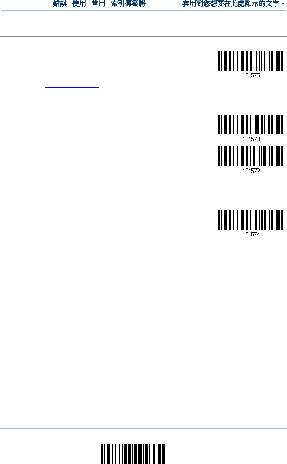
209
Update
Chapter 6
!
! !
!
[
[[
[
]
] ]
]
Heading 1
Heading 1 Heading 1
Heading 1
Field 3
Field 3Field 3
Field 3
Setting
SettingSetting
Setting
1.
Read the barcode below to divide field 3 by a specified terminating string.
Select
Field Separator
to Divide Field 3…
2.
Read the “Hexadecimal Value” barcode on page 242 for the desired character string.
3.
Read the “Validate” barcode to complete this setting.
4.
Read the “Discard Separator” barcode if the field separator is not desired in the field.
*Include Separator
Discard Separator
If not dividing the field by a specific separator, you may divide it by a specified length.
1.
Read the barcode below to divide field 3 by length.
Divide Field 3
by Length
2.
Read the “Decimal Value” barcode on page 241 for the desired field length.
3.
Read the “Validate” barcode on the same page to complete this setting.
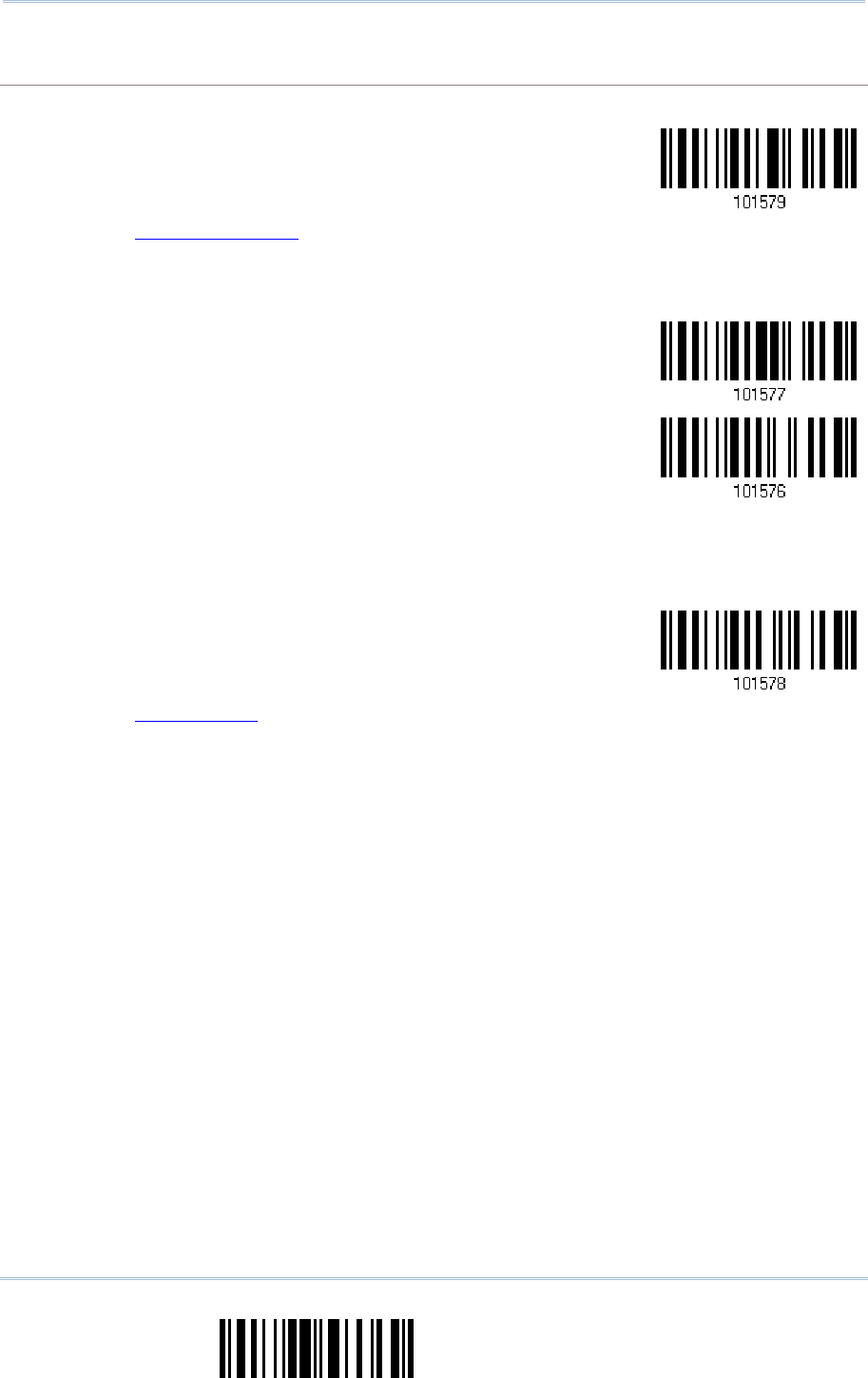
210
End Programming Format
1560/1562 Series Barcode Scanner
User Guide
Field 4
Field 4Field 4
Field 4
S
SS
Setting
ettingetting
etting
1.
Read the barcode below to divide field 4 by a specified terminating string.
Select
Field Separator
to Divide Field 4…
2.
Read the “Hexadecimal Value” barcode on page 242 for the desired character string.
3.
Read the “Validate” barcode to complete this setting.
4.
Read the “Discard Separator” barcode if the field separator is not desired in the field.
*Include Separator
Discard Separator
If not dividing the field by a specific separator, you may divide it by a specified length.
1.
Read the barcode below to divide field 4 by length.
Divide Field 4
by Length
2.
Read the “Decimal Value” barcode on page 241 for the desired field length.
3.
Read the “Validate” barcode on the same page to complete this setting.
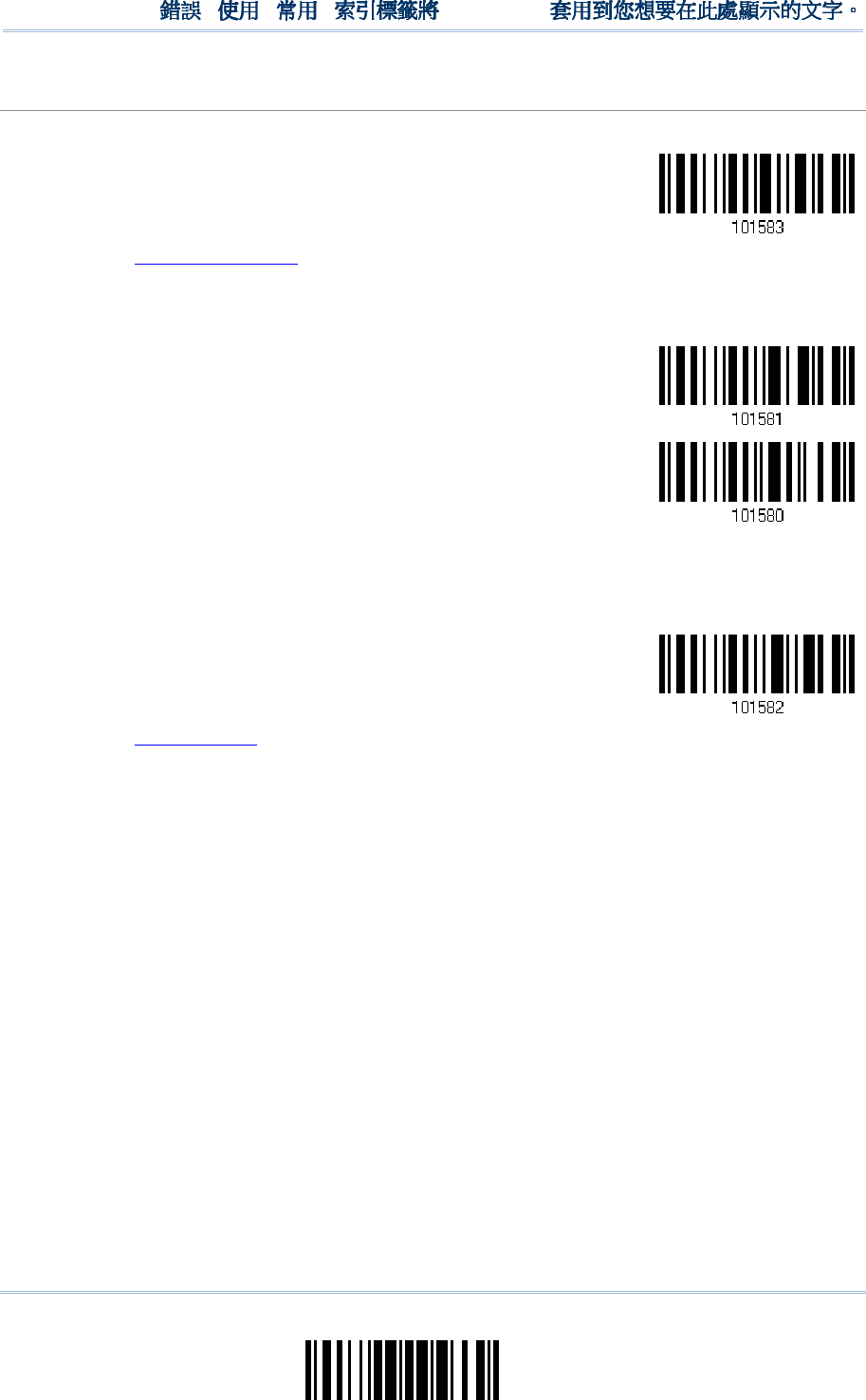
211
Update
Chapter 6
!
! !
!
[
[[
[
]
] ]
]
Heading 1
Heading 1 Heading 1
Heading 1
Field 5
Field 5Field 5
Field 5
Setting
SettingSetting
Setting
1.
Read the barcode below to divide field 5 by a specified terminating string.
Select
Field Separator
to Divide Field 5…
2.
Read the “Hexadecimal Value” barcode on page 242 for the desired character string.
3.
Read the “Validate” barcode to complete this setting.
4.
Read the “Discard Separator” barcode if the field separator is not desired in the field.
*Include Separator
Discard Separator
If not dividing the field by a specific separator, you may divide it by a specified length.
1.
Read the barcode below to divide field 5 by length.
Divide Field 5
by Length
2.
Read the “Decimal Value” barcode on page 241 for the desired field length.
3.
Read the “Validate” barcode on the same page to complete this setting.
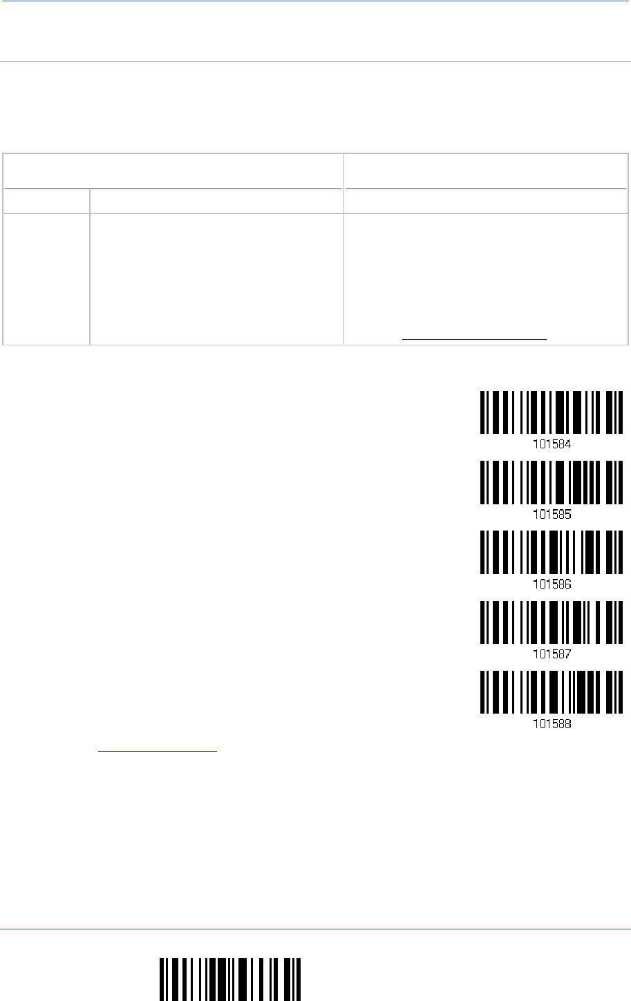
212
End Programming Format
1560/1562 Series Barcode Scanner
User Guide
Additional Fields
Additional FieldsAdditional Fields
Additional Fields
Up to five additional fields can be created for each editing format; each of them is numbered from
AF1 to AF5 accordingly.
If “BT HID”, “USB HID” or “Keyboard Wedge” is configured for interface, Key Type and Key
Status will then become applicable. You may decide whether or not to apply Key Status when
“Normal Key” is selected for Key Type.
Key Type
Key TypeKey Type
Key Type
Key Status
Key StatusKey Status
Key Status
Scan Code
Up to 2 scan code values are allowed.
N/A
Normal Key
Up to 4 character strings are allowed.
Add Shift
Add Left Ctrl
Add Left Alt
Add Right Ctrl
Add Right Alt
Refer to Keyboard Wedge Table.
1.
Read the barcode below to specify an additional field, one at a time.
Additional Field 1…
Additional Field 2…
Additional Field 3…
Additional Field 4…
Additional Field 5…
2.
Read the “Hexadecimal Value” barcode on page 242 for the desired additional field.
3.
Read the “Validate” barcode to complete this setting.

213
Update
Chapter 6
!
! !
!
[
[[
[
]
]]
]
Heading 1
Heading 1 Heading 1
Heading 1
6.4.5 PAUSE FIELD SE
6.4.5 PAUSE FIELD SE6.4.5 PAUSE FIELD SE
6.4.5 PAUSE FIELD SETTING
TTINGTTING
TTING
Pause Field Time
Pause Field TimePause Field Time
Pause Field Time
You can limit the pause time interval (1~16). By default, it is set to 1 second.
Pause Field Time
1~16 sec.
(*1)
1.
Read the barcode above to specify the time interval for the Pause Field. (It is set to 1 by
default.)
2.
Read the “Decimal Value” barcode on page 241. For example, read “1” and “0” for setting the
Pause Field Time to 10 seconds.
3.
Read the “Validate” barcode on the same page to complete this setting.
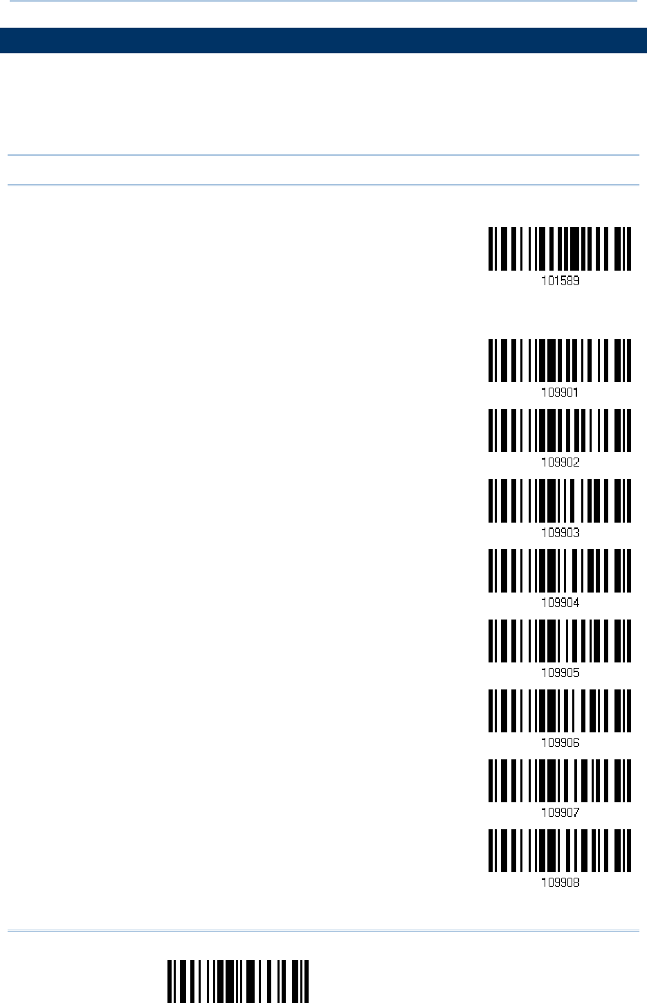
214
End Programming Format
1560/1562 Series Barcode Scanner
User Guide
6.5 CONFIGURING FORM
6.5 CONFIGURING FORM6.5 CONFIGURING FORM
6.5 CONFIGURING FORMAT
AT AT
AT —
——
—
DEFINE TRANSMISSION
DEFINE TRANSMISSION DEFINE TRANSMISSION
DEFINE TRANSMISSION SEQUENCE
SEQUENCESEQUENCE
SEQUENCE
After configuring the data fields and additional fields, you must now program the
transmission sequence of these fields that comprise the final data. This field transmission
sequence can be assigned in any desired order and fields can be assigned multiple times
as well.
Note: Up to twelve fields can be assigned.
1) Read the “Start” barcode to begin with programming the field transmission sequence.
Start Programming…
2) Program the transmission sequence by reading the desired fields as well as additional
fields.
Field 1
Field 2
Field 3
Field 4
Field 5
Field 6
Additional Field 1
Additional Field 2

215
Update
Chapter 6
!
! !
!
[
[[
[
]
] ]
]
Heading 1
Heading 1 Heading 1
Heading 1
Additional Field 3
Additional Field 4
Additional Field 5
Pause Field
Null Character Field
3) Read the “End” barcode to complete this setting.
End Programming…

216
End Programming Format
1560/1562 Series Barcode Scanner
User Guide
6.
6.6.
6.6
66
6
PROGRAMMING EXAMPLES
PROGRAMMING EXAMPLESPROGRAMMING EXAMPLES
PROGRAMMING EXAMPLES
6.
6.6.
6.6
66
6.1 EXAMPLE I
.1 EXAMPLE I.1 EXAMPLE I
.1 EXAMPLE I
Extract data from the 10th character to the 19th character...
Extract data from the 10th character to the 19th character...Extract data from the 10th character to the 19th character...
Extract data from the 10th character to the 19th character...
The editing format should be configured as follows:
1. Read the “Enter Setup” barcode to enter the Configuration Mode.
2. Read the “Configure Format 1” barcode.
3. Read the “Clear All” and “Code 128” barcodes for applicable code type.
4. Read the “Three Fields” barcode.
5. Read the “Divide Field 1 by Length” barcode, and set length to 9.
Field 1 data starts from the 1
st
character to the 9
th
character.
6. Read the “Divide Field 2 by Length” barcode, and set length to 10.
Field 2 data starts from the 10
th
character to the 19
th
character.
7. Read the “Start (Programming)” barcode to program the transmission sequence.
8. Read the “Field 2” barcode.
9. Read the “End” barcode to complete the transmission sequence setting.
10.
Read the “End Programming Format” barcode to complete the setting of Editing Format 1.
11.
Read the “Enable Format 1” barcode to apply Editing Format 1 to Code 128.
12.
Read the “Update” barcode to exit the Configuration Mode.

217
Update
Chapter 6
!
! !
!
[
[[
[
]
] ]
]
Heading 1
Heading 1 Heading 1
Heading 1
6
66
6.
..
.6
66
6.2 EXAMPLE II
.2 EXAMPLE II.2 EXAMPLE II
.2 EXAMPLE II
Extract the date code, item number, and quantity information from barcodes.
Extract the date code, item number, and quantity information from barcodes.Extract the date code, item number, and quantity information from barcodes.
Extract the date code, item number, and quantity information from barcodes.
Data in a barcode is encoded like this:
From the 1
st
character to the 6
th
character is the date code.
From the 7
th
character to the dash ‘-’ character is the item number.
After the dash ‘-’ character is the quantity information.
Data will be transmitted like this:
The item number goes first, then a TAB character, followed by the date code, then another TAB
character, and finally the quantity information.
The editing format should be configured as follows:
1. Read the “Enter Setup” barcode to enter the Configuration Mode.
2. Read the “Configure Format 2” barcode.
3. Read the “Three Fields” barcode.
4. Read the “Divide Field 1 by Length” barcode, and set length to 6.
Field 1 data starts from the 1
st
character to the 6
th
character.
5. Read the “Select Field Separator to Divide Field 2” barcode, and use a dash ‘-’ character.
Field 2 data starts from the 7
th
character until the dash ‘-’ character is met.
6. Read the “Additional Field 1” barcode, and use a tab character for the field.
7. Read the “Start (Programming)” barcode to program the transmission sequence.
8. Read the “Field 2”, “Additional Field 1”, “Field 1”, “Additional Field 1”, “Field 3” barcodes.
9. Read the “End” barcode to complete the transmission sequence (F2 A1 F1 A1 F3) setting.
10.
Read the “End Programming Format” barcode to complete the setting of Editing Format 1.
11.
Read the “Enable Format 2” barcode to apply Editing Format 2 to all code types.
12.
Read the “Update” barcode to exit the Configuration Mode.

218
End Programming Format
1560/1562 Series Barcode Scanner
User Guide
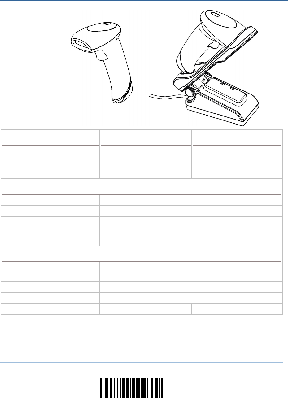
219
Update
Optical Characteristi
Optical CharacteristiOptical Characteristi
Optical Characteristics
cscs
cs
1560
15601560
1560
1562
15621562
1562
Scan Engine Non-contact type Non-contact type
Optical Sensor CCD, 2500 pixels Laser
Light Source Visible red LED Visible laser diode
RF Characteristics
RF CharacteristicsRF Characteristics
RF Characteristics
WPAN Module Wireless PAN BT Class 2 compliance
Coverage (line-of-sight) 90 meters with 3656 CRADLE
Interface Supported
Serial Port Profile (BT SPP)
Human Interface Device Profile (BT HID)
3656 CRADLE
Physical Characteristics
Physical CharacteristicsPhysical Characteristics
Physical Characteristics
Memory
4 KB for transmit buffer
512 KB flash for memory mode
Switch Tactile switch
Indication Triple-color LED (Red/Green/Blue) and beeper
Weight Approx. 170 g Approx. 175 g
SPECIFICATIONS
SPECIFICATIONSSPECIFICATIONS
SPECIFICATIONS
220
Enter Setup
1560/1562 Series Barcode Scanner
User Guide
Electrical Characteristics
Electrical CharacteristicsElectrical Characteristics
Electrical Characteristics
Battery Rechargeable Li-ion battery – 3.7 V, 800 mAh
Power Adapt
Power AdaptPower Adapt
Power Adapto
oo
or
rr
r
Input AC 100~240 V, 50/60 Hz
Output DC 5V, 2A (3656 CRADLE)
DC 5V 0.5A (Battery Charger)
Operating Temperature 0 °C to 40 °C
Environmental Characteristics
Environmental CharacteristicsEnvironmental Characteristics
Environmental Characteristics
Temperature Operating
Storage
0 °C to 50 °C
-20 °C to 60 °C
Humidity
(Non-condensing)
Operating
Storage
10% to 90%
5% to 95%
Resistance
ResistanceResistance
Resistance
Impact Resistance 1.2 m, 5 drops per 6 sides
Splash / Dust Resistance IP 30
Electrostatic Discharge ± 15 kV air discharge, ± 8 kV contact discharge
Programming Support
Programming SupportProgramming Support
Programming Support
Configuration via Setup Barcodes
Use setup barcodes or host serial commands.
Software Windows
®
-based ScanMaster
Firmware upgradeable Download firmware updates via the download utility.
Accessories (
Accessories (Accessories (
Accessories (√
√√
√
means “supported”)
means “supported”)means “supported”)
means “supported”)
Rechargeable Li-ion Battery √ √
Battery Charger √ √
3656 CRADLE Stand √ √
USB Cable √ √
RS-232 Cable √ √
Keyboard Wedge Cable √ √
Note: The 3656 CRADLE stand is not only an Auto-Sense stand (for 1560 only) and
capable of charging the 1560/1562 scanner, but specifically designed for the
scanner to communicate with a host computer wirelessly.
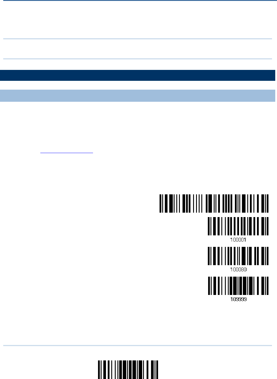
221
Update
You can only upgrade firmware of one scanner at a time. For example, you must turn off
each of the rest 1560/1562 scanners when there is more than one scanner connected to
your computer.
Note: In case it fails downloading due to low battery, make sure the targe scanner is
loaded with good battery and the battery charge is enough.
HOW TO UPGRADE 1560
HOW TO UPGRADE 1560HOW TO UPGRADE 1560
HOW TO UPGRADE 1560/1562
/1562/1562
/1562
FIRMWARE
FIRMWAREFIRMWARE
FIRMWARE
USING
USING USING
USING 3656
36563656
3656
CRADLE
CRADLECRADLE
CRADLE
1) Connect the interface cable, RS-232 or USB, between 3656 CRADLE and your
computer.
For USB Virtual COM, you may need to install its driver first!
2) Connect the power supply cord from 3656 CRADLE to a proper power outlet.
3) Refer to 3.1.1 Connect to for the target scanner to connect to 3656 CRADLE.
Read the “Set Connection” label first, and then the “Serial Number” label. Both labels
can be located at the back of 3656 CRADLE.
4) Read the following barcodes in sequence to configure the scanner to use RS-232 as
download interface.
Enter Setup
Activate 3656 CRADLE
RS-232
115200 bps
Update
Or, read the following barcodes in sequence to configure the scanner to use USB
Virtual COM as download interface.
Appendix
Appendix Appendix
Appendix
I
II
I
FIRMWARE
FIRMWAREFIRMWARE
FIRMWARE
UPGR
UPGRUPGR
UPGRADE
ADEADE
ADE
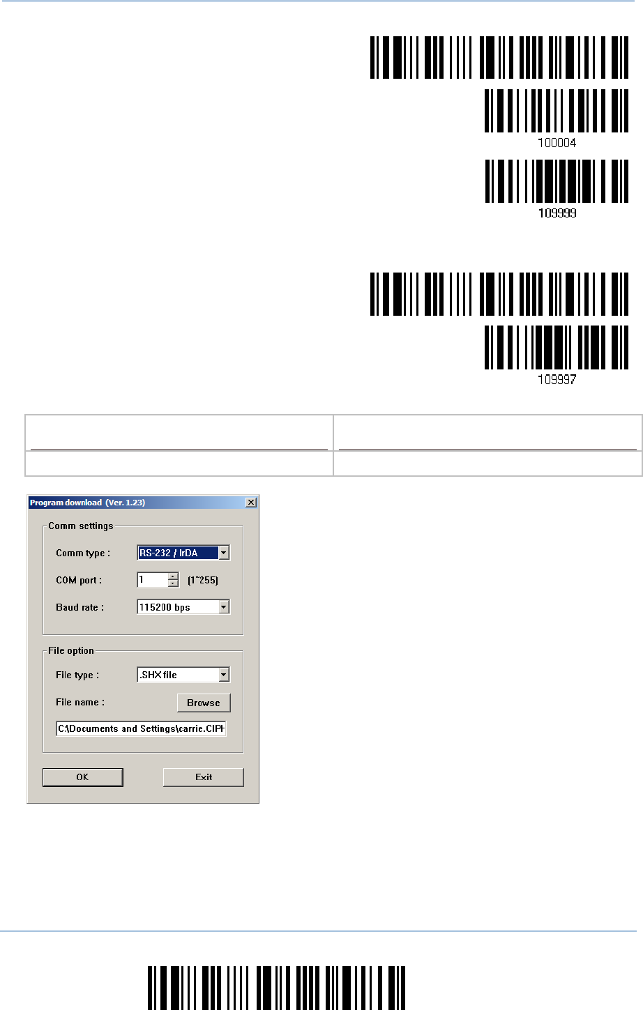
222
Enter Setup
1560/1562 Series Barcode Scanner
User Guide
Enter Setup
Activate 3656 CRADLE
USB Virtual COM
Update
5) Read the following barcodes in sequence for the scanner to enter the download mode.
The scanner will respond with beeps to indicate it is ready for downloading.
Enter Setup
Download
6) Run the download utility “ProgLoad.exe” on your computer.
Kernel Program
Kernel ProgramKernel Program
Kernel Program
User Program
User ProgramUser Program
User Program
K1560_V*.shx STD1560_V*.shx
For the communication settings, select
“RS-232” and the correct COM port for
RS-232 or USB Virtual COM interface.
For RS-232, select 115200 bps for baud
rate; for USB Virtual COM, ignore the baud
rate setting.
For the file option, click [Browse] to select
the target file for firmware update.
Click [OK].
7) After upgrading kernel, you will need to manually restart the scanner.
After upgrading the user program, the scanner will automatically restart itself once
the download is completed successfully.

223
Update
Appendix I
!
! !
!
[
[[
[
]
] ]
]
Heading 1
Heading 1 Heading 1
Heading 1
Note: The output interface remains unchanged as specified in step 3 (= RS-232 or USB
Virtual COM). For RS-232, the baud rate setting is still 115200 bps!
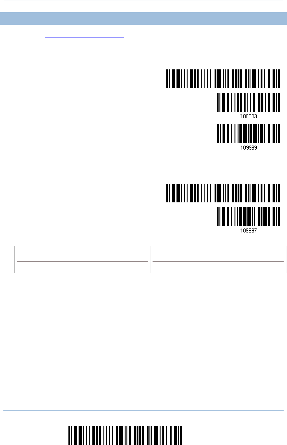
224
Enter Setup
1560/1562 Series Barcode Scanner
User Guide
USING
USING USING
USING BLUETOOTH
BLUETOOTHBLUETOOTH
BLUETOOTH
®
®®
®
DONGLE
DONGLEDONGLE
DONGLE
1) Refer to 3.2.3 Connect to Dongle for the target scanner to accept the connection
request from your computer.
2) Read the following barcodes in sequence to configure the scanner to use BT SPP as
download interface.
Enter Setup
Activate BT SPP
Update
3) Read the following barcodes in sequence for the scanner to enter the download mode.
The scanner will respond with beeps to indicate it is ready for downloading.
Enter Setup
Download
4) Run the download utility “ProgLoad.exe” on your computer.
Kernel Program
Kernel ProgramKernel Program
Kernel Program
User Program
User ProgramUser Program
User Program
K1560_V*.shx STD1560_V*.shx
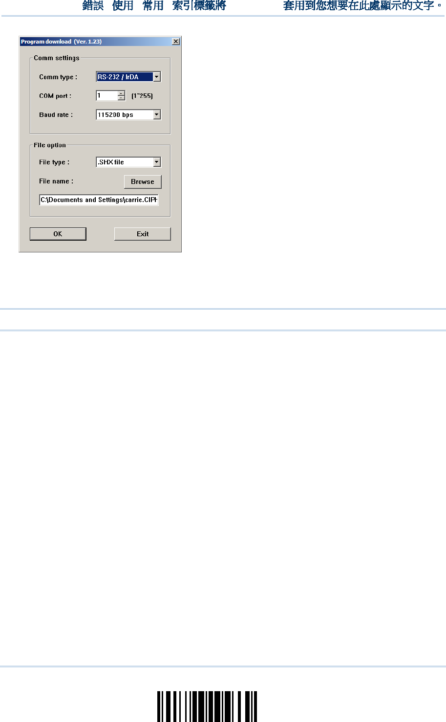
225
Update
Appendix I
!
! !
!
[
[[
[
]
] ]
]
Heading 1
Heading 1Heading 1
Heading 1
For the communication settings, select
“RS-232” and the correct COM port for BT
SPP interface.
Ignore the baud rate setting.
For the file option, click [Browse] to select
the target file for firmware update.
Click [OK].
5) After upgrading kernel, you will need to manually restart the scanner.
After upgrading the user program, the scanner will automatically restart itself once
the download is completed successfully.
Note: The output interface remains unchanged as specified in step 2 (= BT SPP).
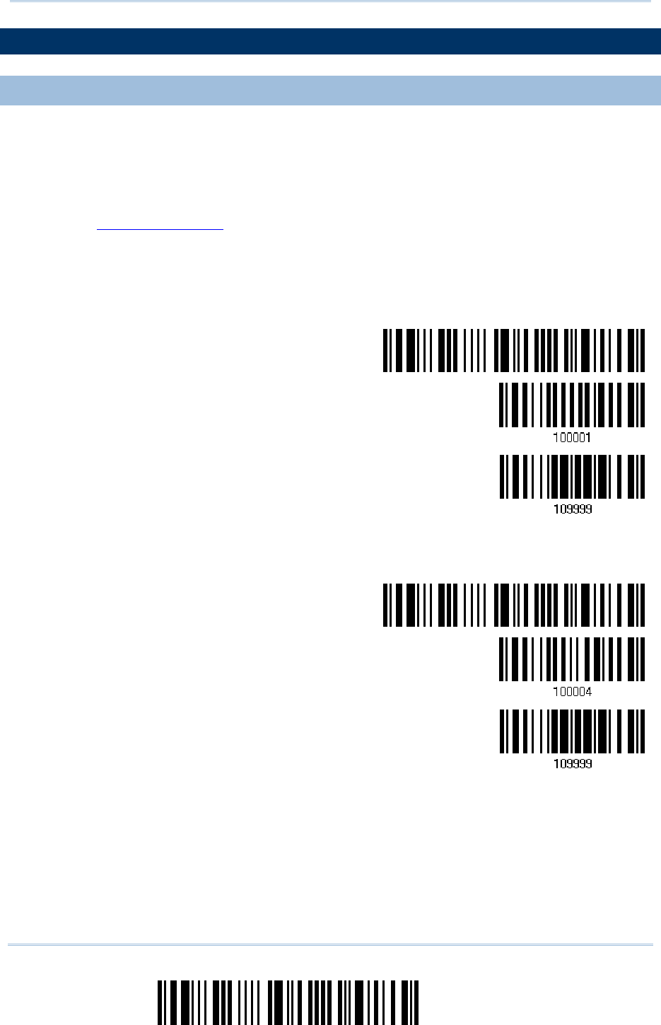
226
Enter Setup
1560/1562 Series Barcode Scanner
User Guide
HOW TO UPGRADE
HOW TO UPGRADE HOW TO UPGRADE
HOW TO UPGRADE 3656
36563656
3656
CRADLE
CRADLECRADLE
CRADLE
FIRMWARE
FIRMWAREFIRMWARE
FIRMWARE
UPGRADING
UPGRADING UPGRADING
UPGRADING 3656
36563656
3656
CRADLE
CRADLECRADLE
CRADLE
CPU FIRMWARE
CPU FIRMWARE CPU FIRMWARE
CPU FIRMWARE
1) Connect the interface cable, RS-232 or USB, between 3656 CRADLE and your
computer.
For USB Virtual COM, you may need to install its driver first!
2) Connect the power supply cord from 3656 CRADLE to a proper power outlet.
3) Refer to 3.1.1 Connect to for the target scanner to connect to 3656 CRADLE.
Read the “Set Connection” label first, and then the “Serial Number” label. Both labels
can be located at the back of 3656 CRADLE.
4) Read the following barcodes in sequence to configure the scanner to use RS-232 as
download interface.
Enter Setup
Activate 3656 CRADLE
RS-232
Update
Or, read the following barcodes in sequence to configure the scanner to use USB
Virtual COM as download interface.
Enter Setup
Activate 3656 CRADLE
USB Virtual COM
Update
5) Read the following barcodes in sequence for 3656 CRADLE to enter the download
mode. The Communication LED on 3656 CRADLE will be flashing red to indicate it is
ready for downloading.
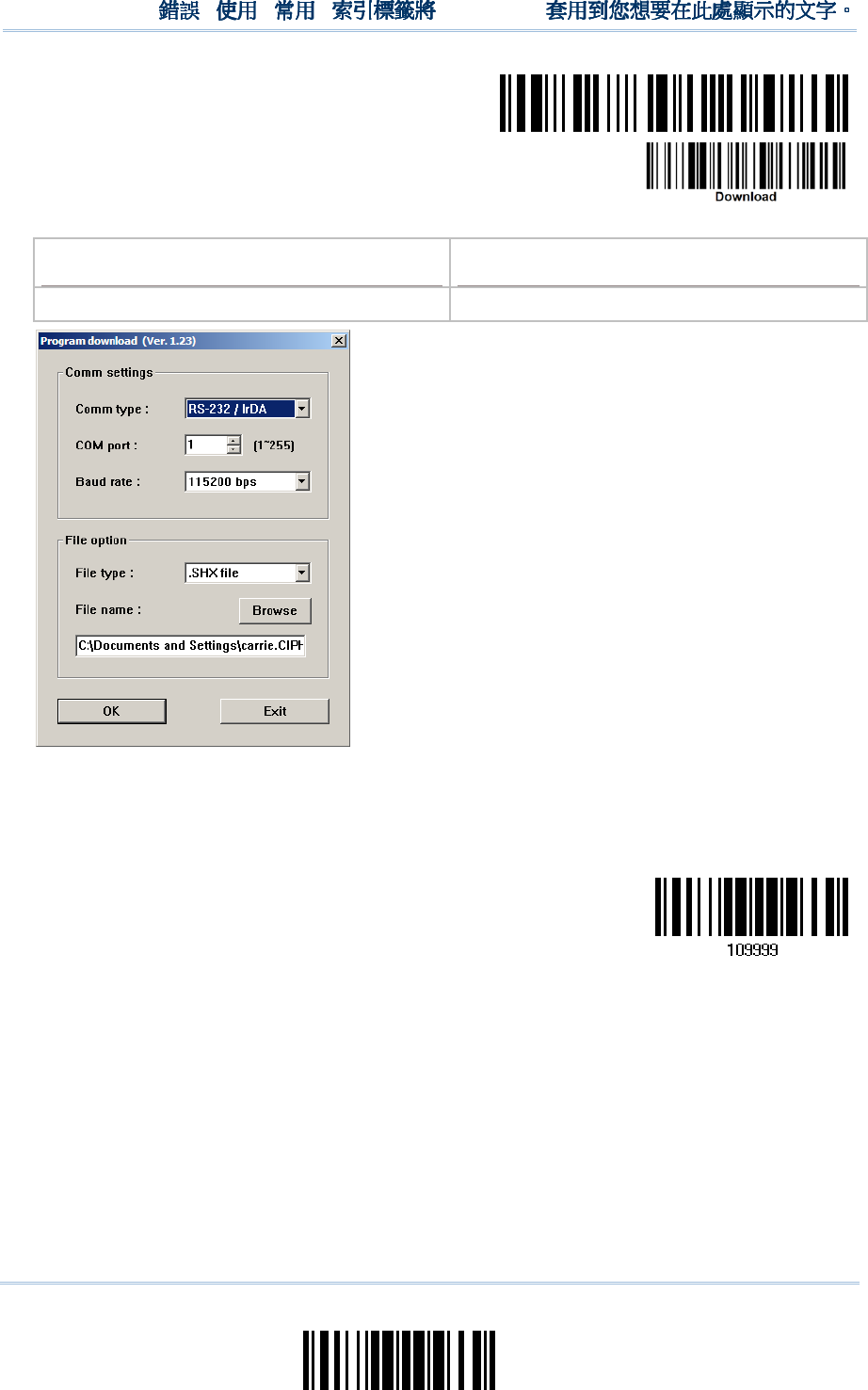
227
Update
Appendix I
!
! !
!
[
[[
[
]
] ]
]
Heading 1
Heading 1 Heading 1
Heading 1
Enter Setup
Download 3656 CRADLE
CPU Firmware
6) Run the download utility “ProgLoad.exe” on your computer.
Kernel Program
Kernel ProgramKernel Program
Kernel Program
User Program
User ProgramUser Program
User Program
K3656 CRADLE _V*.shx STD3656 CRADLE _V*.shx
For the communication settings, select
“RS-232” and the correct COM port for
RS-232 or USB Virtual COM interface.
For RS-232, select 115200 bps for baud
rate; for USB Virtual COM, ignore the baud
rate setting.
For the file option, click [Browse] to select
the target file for firmware update.
Click [OK].
7) The 3656 CRADLE will automatically restart itself when upgrading firmware is
completed successfully.
8) Read the “Update” barcode for the scanner to resume its operation (exit the
configuration mode).
Update
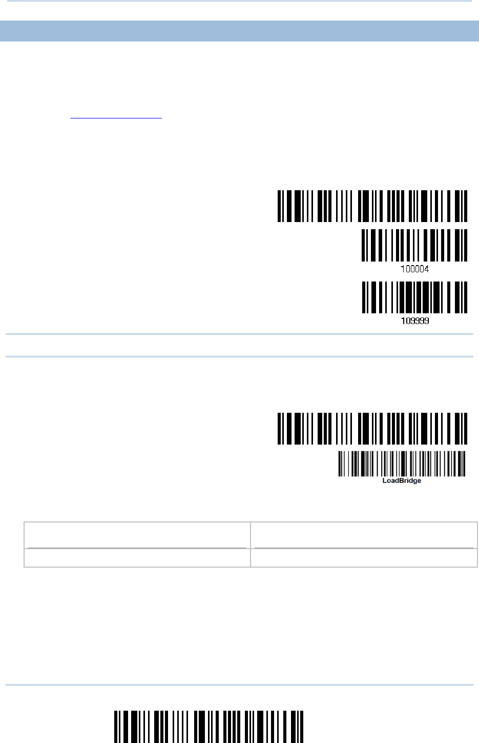
228
Enter Setup
1560/1562 Series Barcode Scanner
User Guide
UPGRADING
UPGRADING UPGRADING
UPGRADING 3656
36563656
3656
CRADLE
CRADLECRADLE
CRADLE
USB BRIDGE FIRMWARE
USB BRIDGE FIRMWAREUSB BRIDGE FIRMWARE
USB BRIDGE FIRMWARE
1) Connect the USB cable between 3656 CRADLE and your computer.
For USB Virtual COM, you may need to install its driver first!
2) Connect the power supply cord from 3656 CRADLE to a proper power outlet.
3) Refer to 3.1.1 Connect to for the target scanner to connect to 3656 CRADLE.
Read the “Set Connection” label first, and then the “Serial Number” label. Both labels
can be located at the back of 3656 CRADLE.
4) Read the following barcodes in sequence to configure the scanner to use USB Virtual
COM as download interface.
Enter Setup
Activate 3656 CRADLE
USB Virtual COM
Update
Note: You can download USB Bridge firmware via USB Virtual COM only!
5) Read the following barcodes in sequence for 3656 CRADLE to enter the download
mode. The Communication LED on 3656 CRADLE will be flashing red to indicate it is
ready for downloading.
Enter Setup
Download 3656 CRADLE
USB Bridge Firmware
6) Run the download utility “ProgLoad.exe” on your computer.
Kernel Program
Kernel ProgramKernel Program
Kernel Program
User Program
User ProgramUser Program
User Program
K3656 CRADLE Bridge_V*.shx STD3656 CRADLE Bridge_V*.shx
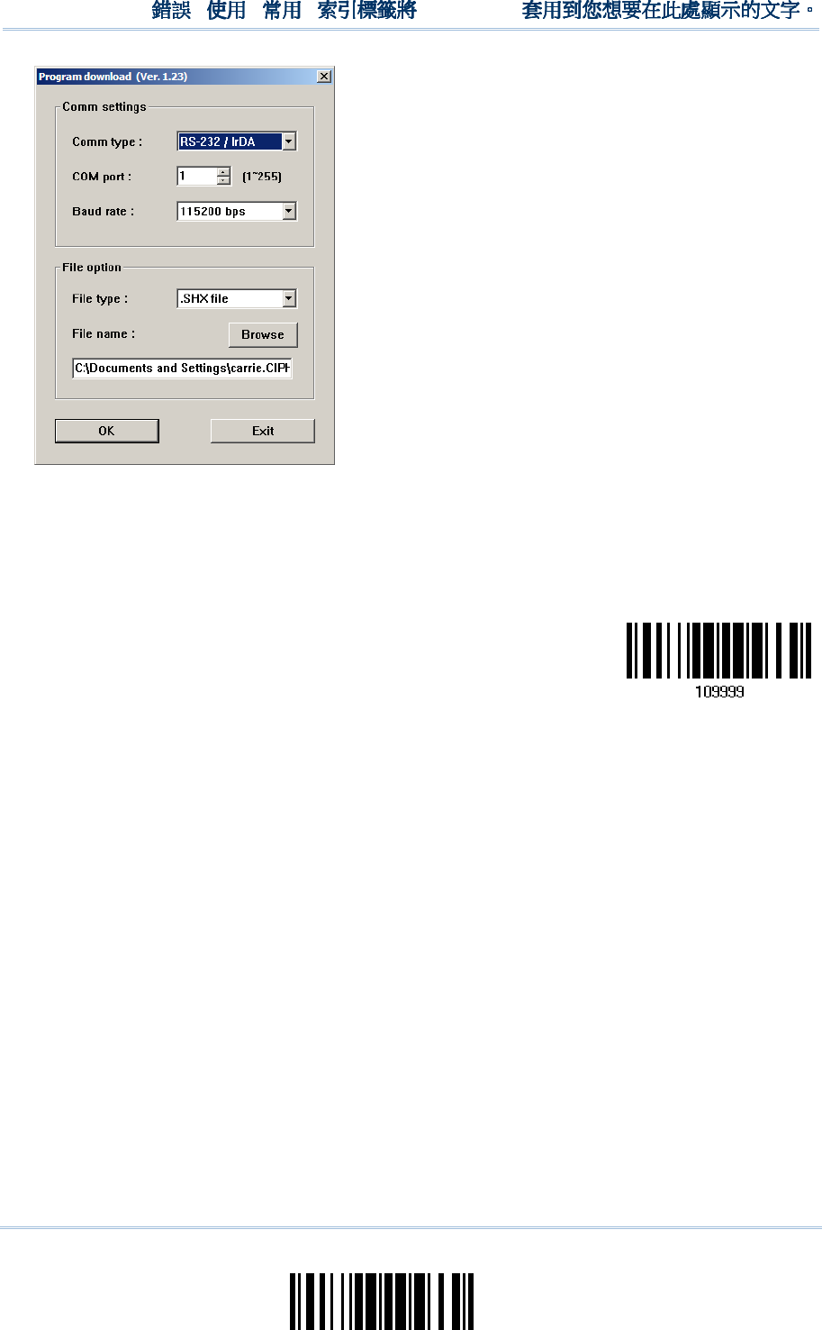
229
Update
Appendix I
!
! !
!
[
[[
[
]
] ]
]
Heading 1
Heading 1 Heading 1
Heading 1
For the communication settings, select
“RS-232” and the correct COM port for USB
Virtual COM interface.
Ignore the baud rate setting.
For the file option, click [Browse] to select
the target file for firmware update.
Click [OK].
7) The 3656 CRADLE will automatically restart itself when upgrading firmware is
completed successfully.
8) Read the “Update” barcode for the scanner to resume its operation (exit the
configuration mode).
Update

230
Enter Setup
1560/1562 Series Barcode Scanner
User Guide
231
Update
1560
15601560
1560/1562
/1562/1562
/1562
SERIAL COMMANDS
SERIAL COMMANDSSERIAL COMMANDS
SERIAL COMMANDS
D
DD
D
Purpose To disable the scanner.
Remarks “D”
E
EE
E
Purpose To enable the scanner.
Remarks “E”
#@
#@#@
#@
nnnnnn
nnnnnnnnnnnn
nnnnnn
<CR>
<CR><CR>
<CR>
Purpose To configure the scanner.
Remarks nnnnnn – the six digits of command parameters.
For example, “109952” is to list the current Code ID settings.
“0x23” + “0x40” + “0x31” + “0x30” + “0x39” + “0x39” + “0x35” + “0x32” + “0x0d”
Note: After configuring the scanner, you may send the serial command “#@109999” to
save the settings.
#@
#@ #@
#@ -
--
-
-
--
-
-
--
-
-
--
-<CR>
<CR><CR>
<CR>
Purpose To halt the scanner.
Remarks “0x23” + “0x40” + “0x2d” + “0x2d” + “0x2d” + “0x2d” + “0x0d”
#@ . . . . <CR>
#@ . . . . <CR>#@ . . . . <CR>
#@ . . . . <CR>
Purpose To resume operation.
Remarks “0x23” + “0x40” + “0x2e” + “0x2e” + “0x2e” + “0x2e” + “0x0d”
#@////<CR>
#@////<CR>#@////<CR>
#@////<CR>
Purpose To respond with a beep.
Remarks “0x23” + “0x40” + “0x2f” + “0x2f” + “0x2f” + “0x2f” + “0x0d”
Appendix
Appendix Appendix
Appendix
II
IIII
II
HOST S
HOST SHOST S
HOST SERIAL COMMANDS
ERIAL COMMANDSERIAL COMMANDS
ERIAL COMMANDS
Serial Command
List Page 3

232
Enter Setup
1560/1562 Series Barcode Scanner
User Guide
#@TRIGOFF<CR>
#@TRIGOFF<CR>#@TRIGOFF<CR>
#@TRIGOFF<CR>
Purpose To disable the software trigger
Remarks “0x23” + “0x40” + “0x54” + “0x52” + “0x49” + “0x47” + “0x4f” + “0x46” +
“0x46” + “0x0d”
#@TRIGON<CR>
#@TRIGON<CR>#@TRIGON<CR>
#@TRIGON<CR>
Purpose To enable the software trigger
Remarks “0x23” + “0x40” + “0x54” + “0x52” + “0x49” + “0x47” + “0x4f” + “0x4e” +
“0x0d”
#@
#@#@
#@RDSN
RDSNRDSN
RDSN<CR>
<CR><CR>
<CR>
Purpose Read serial number
Remarks “0x23” + “0x40” + “0x52” + “0x44” + “0x53” + “0x4E” + “0x0D”
EXAMPLE
EXAMPLEEXAMPLE
EXAMPLE
You may run HyperTerminal.exe on the host computer to send serial commands to the
1560/1562 scanner via RS-232, USB Virtual COM or BT SPP.
For the scanner to stop immediately –
D
For the scanner to resume working –
E
For the scanner to change the beeper to medium volume and beep –
#@101011<CR>
#@////<CR>
For the scanner to change the beeper to minimal volume and beep –
#@101010<CR>
#@////<CR>
For the scanner to change the beeper frequency to 8 kHz (for Good Read Beep only)
and beep –
#@101001<CR>
#@////<CR>
For the scanner to change the beeper length to longest (for Good Read Beep only)
and beep –
#@101008<CR>
#@////<CR>
For the scanner to save the settings, send the serial command “#@109999” –
#@101011<CR>
#@109999<CR>

233
Update
Appendix II
!
! !
!
[
[[
[
]
] ]
]
Heading 1
Heading 1 Heading 1
Heading 1
For the scanner to read the serial number and beep –
#@RDSN<CR>
#@////<CR>
Note: (1) For RS-232 or USB Virtual COM, you can only configure the first scanner that
connects to 3656 CRADLE. To identify the scanner, you may send the serial
command to have it respond with a beep.
(2) For BT SPP, you can configure up to seven scanners at the same time.
3656
36563656
3656
CRADLE
CRADLECRADLE
CRADLE
SETUP
SETUP SETUP
SETUP BARCODE
BARCODEBARCODE
BARCODES &
S & S &
S & SERIAL COMMANDS
SERIAL COMMANDSSERIAL COMMANDS
SERIAL COMMANDS
Normally, you can configure the 3656 CRADLE stand by having a connected scanner read
3656 CRADLE -related setup barcodes.
1) Connect the interface cable, RS-232, Keyboard Wedge or USB, between 3656
CRADLE and your computer.
For USB Virtual COM, you may need to install its driver first!
2) Connect the power supply cord from 3656 CRADLE to a proper power outlet.
3) Refer to 3.1.1 Connect to for the target scanner to connect to 3656 CRADLE.
Read the “Set Connection” label first, and then the “Serial Number” label. Both labels
can be located at the back of 3656 CRADLE.
4) Read the following barcodes in sequence to configure 3656 CRADLE.
Enter Setup
Update
For 3656 CRADLE -related setup barcodes, refer to the Serial Command table below.
Note that for the “Version” and “GetID” barcodes, you must run HyperTerminal.exe or
any text editor to receive the information.
If the output interface is RS-232 or USB Virtual COM, run HyperTerminal.exe on
your computer to receive the information.
If the output interface is Keyboard Wedge or USB HID, run any text editor to
receive the information.
(3656-related setup barcodes)
234
Enter Setup
1560/1562 Series Barcode Scanner
User Guide
3656
36563656
3656
CRADLE
CRADLECRADLE
CRADLE
SETUP BARCODES
SETUP BARCODESSETUP BARCODES
SETUP BARCODES
Config
ConfigConfig
Config<CR>
<CR><CR>
<CR>
Purpose To configure 3656 CRADLE.
Here is the setup barcode for this serial command:
Config
Remarks A list of the current settings will be displayed. Run HyperTerminal.exe on your
computer and change the settings one by one.
DefaultSetting
DefaultSettingDefaultSetting
DefaultSetting<CR>
<CR><CR>
<CR>
Purpose To restore the default settings.
Here is the setup barcode for this serial command:
DefaultSetting
SingleConnection
SingleConnectionSingleConnection
SingleConnection<CR>
<CR><CR>
<CR>
Purpose To allow only one scanner connecting to 3656 CRADLE.
Here is the setup barcode for this serial command:
SingleConnection
Multi
MultiMulti
MultiCon
ConCon
Connection
nectionnection
nection<CR>
<CR><CR>
<CR>
Purpose To allow up to seven scanners connecting to 3656 CRADLE.
Here is the setup barcode for this serial command:
MultiConnection
UseOnePortforAll
UseOnePortforAllUseOnePortforAll
UseOnePortforAll<CR>
<CR><CR>
<CR>
Purpose To use one Virtual COM port for all whenever connecting 3656 CRADLE to PC via
USB. This setting requires you to connect one 3656 CRADLE at a time, and will
facilitate configuring a great amount of 3656 CRADLE via the same Virtual COM port
(for administrators’ or factory use).
Here is the setup barcode for this serial command:
UseOnePortforAll
235
Update
Appendix II
!
! !
!
[
[[
[
]
] ]
]
Heading 1
Heading 1 Heading 1
Heading 1
UseVariablePort
UseVariablePortUseVariablePort
UseVariablePort<CR>
<CR><CR>
<CR>
Purpose To use variable Virtual COM port when connecting more than one 3656 CRADLE to
PC via USB.
Here is the setup barcode for this serial command:
UseVariablePort
Version
VersionVersion
Version<CR>
<CR><CR>
<CR>
Purpose To get the firmware versions (CPU+USB Bridge).
Here is the setup barcode for this serial command:
Version
GetID
GetIDGetID
GetID<CR>
<CR><CR>
<CR>
Purpose To get MAC ID.
Here is the setup barcode for this serial command:
GetID
Download
DownloadDownload
Download<CR>
<CR><CR>
<CR>
Purpose To download CPU firmware to 3656 CRADLE via RS-232 or USB.
Here is the setup barcode for this serial command:
Download
LoadBridge
LoadBridgeLoadBridge
LoadBridge<CR>
<CR><CR>
<CR>
Purpose To download USB Bridge firmware to 3656 CRADLE via USB only.
Here is the setup barcode for this serial command:
LoadBridge
236
Enter Setup
1560/1562 Series Barcode Scanner
User Guide
EXAMPLE
EXAMPLEEXAMPLE
EXAMPLE
Without using the scanner to read the above setup barcodes for configuring the 3656
CRADLE stand, you may run HyperTerminal.exe on the host computer to send serial
commands to 3656 CRADLE via RS-232 or USB.
1) Connect the interface cable, RS-232 or USB, between 3656 CRADLE and your
computer.
For USB Virtual COM, you may need to install its driver first!
2) Connect the power supply cord from 3656 CRADLE to a proper power outlet.
The Communication LED will indicate when 3656 CRADLE can accept serial commands
after initializing. Refer to the table below.
If the output interface is USB Virtual COM or RS-232, run HyperTerminal.exe on
your computer. While the Communication LED on 3656 CRADLE is purple (red with
flashing blue), type the serial command within three seconds.
If the output interface is USB HID, press the “Num Lock” or “Caps Lock” key on
your keyboard 5 times within 3 seconds while the Communication LED on 3656
CRADLE is flashing red and blue. This will change the interface from USB HID to
USB Virtual COM and the Communication LED will become purple (red with
flashing blue). Then, run HyperTerminal.exe on your computer. While the
Communication LED on 3656 CRADLE is purple (red with flashing blue), type the
serial command within three seconds. After configuring via serial commands, the
interface will be reset to USB HID after re-connecting the power supply cord.
Communication LED
Communication LEDCommunication LED
Communication LED
M
MM
Meaning
eaningeaning
eaning
--- Blue,
solid
Initialize
Red,
solid
Blue,
flashing
Serial command mode with USB Virtual COM or RS-232: wait 3 seconds for
starting a serial command
Red,
flashing
Blue,
flashing
Serial command mode with USB HID changed to USB Virtual COM first: wait
3 seconds for pressing [Num Lock] or [Caps Lock] 5 times via keyboard

237
Update
0
1
2
3
4
5
6
7
8
0 F2 SP 0 @ P ` p
1 INS F3 ! 1 A Q a q
2 DLT F4 " 2 B R b r
3 Home F5 # 3 C S c s
4 End F6 $ 4 D T d t
5 Up F7 % 5 E U e u
6 Down F8 & 6 F V f v
7 Left F9 ' 7 G W g w
8 BS F10 ( 8 H X h x
9 HT F11 ) 9 I Y i y
A LF F12 * : J Z j z
B Right ESC + ; K [ k {
C PgUp Exec , < L \ l |
D CR CR* - = M ] m }
E PgDn . > N ^ n ~
F F1 / ? O _ o Dly ENTER*
Note: (1) ~: Digits of numeric keypad.
(2) CR*/ENTER*: ENTER key on the numeric keypad.
Appendix
Appendix Appendix
Appendix
III
IIIIII
III
KEYBOARD WEDGE TABLE
KEYBOARD WEDGE TABLEKEYBOARD WEDGE TABLE
KEYBOARD WEDGE TABLE
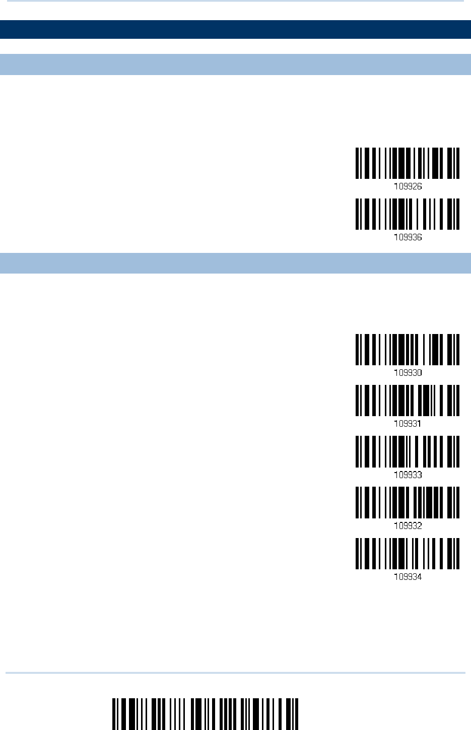
238
Enter Setup
1560/1562 Series Barcode Scanner
User Guide
KEY TYPE
KEY TYPEKEY TYPE
KEY TYPE
& STATUS
& STATUS& STATUS
& STATUS
KEY TYPE
KEY TYPEKEY TYPE
KEY TYPE
If “BT HID”, “USB HID” or “Keyboard Wedge” is configured for interface, Key Type and
Key Status will then become applicable.
*Normal
Scan Code
KEY STATUS
KEY STATUSKEY STATUS
KEY STATUS
Decide whether or not to change key status when “Normal Key” is selected for Key Type.
Add Shift
Add Left Ctrl
Add Right Ctrl
Add Left Alt
Add Right Alt

239
Update
Appendix III
!
! !
!
[
[[
[
]
] ]
]
Heading 1
Heading 1 Heading 1
Heading 1
EXAMPLE
EXAMPLEEXAMPLE
EXAMPLE
KEY TYPE = NORMAL
KEY TYPE = NORMALKEY TYPE = NORMAL
KEY TYPE = NORMAL
For example, if you want to program the character “!” as the prefix code:
1. Read the “Configure Prefix” barcode.
2. Read the “Hexadecimal Value” barcode on page 242 for “2” and “1”.
3. Read the “Validate” barcode to complete this setting.
KEY TYPE = SCAN CODE
KEY TYPE = SCAN CODEKEY TYPE = SCAN CODE
KEY TYPE = SCAN CODE
For example, if you want to program the character “a” (= “1C” on the scan code table) as the
prefix code:
1. Read the “Configure Prefix” barcode.
2. Read the “Scan Code” barcode.
3. Read the “Hexadecimal Value” barcode on page 242 for “1” and “C”.
4. Read the “Validate” barcode to complete this setting.
KEY TYPE = NORMAL +
KEY TYPE = NORMAL + KEY TYPE = NORMAL +
KEY TYPE = NORMAL + KEY STATUS = SHIFT
KEY STATUS = SHIFTKEY STATUS = SHIFT
KEY STATUS = SHIFT
For example, if you want to program the character “!” (= “Shift” + “1” on keyboard) as the prefix
code:
1. Read the “Configure Prefix” barcode.
2. Read the “Add Shift” barcode.
3. Read the “Hexadecimal Value” barcode on page 242 for “3” and “1”.
4. Read the “Validate” barcode to complete this setting.
KEY TYPE = NORMAL +
KEY TYPE = NORMAL + KEY TYPE = NORMAL +
KEY TYPE = NORMAL + KEY STATUS
KEY STATUSKEY STATUS
KEY STATUS
= CTRL
= CTRL= CTRL
= CTRL
For example, if you want to program “Ctrl+A” and “Ctrl+$” as the prefix code:
1. Read the “Configure Prefix” barcode.
2. Read the “Add Left Ctrl” barcode.
3. Read the “Hexadecimal Value” barcode on page 242 for “4”, “1” (= “A”).
4. Read the “Add Left Ctrl” barcode.
5. Read the “Hexadecimal Value” barcode on page 242 for “2”, “4” (= “$”).
6. Read the “Validate” barcode to complete this setting.

240
Enter Setup
1560/1562 Series Barcode Scanner
User Guide
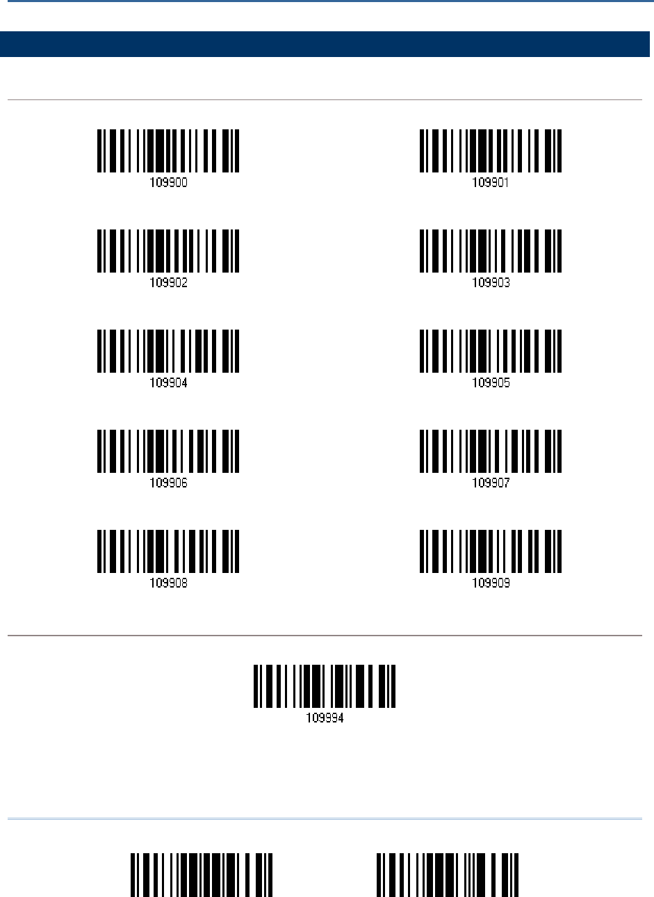
241
Update Abort
DECIMAL SYSTEM
DECIMAL SYSTEMDECIMAL SYSTEM
DECIMAL SYSTEM
Decimal
DecimalDecimal
Decimal
Validate the Values
Validate the ValuesValidate the Values
Validate the Values
Appendix
Appendix Appendix
Appendix
IV
IVIV
IV
NUMERAL SYSTEMS
NUMERAL SYSTEMSNUMERAL SYSTEMS
NUMERAL SYSTEMS
0
1
2 3
4
5
6 7
8 9
Validate
242
Enter Setup
1560/1562 Series Barcode Scanner
User Guide
HEXADECIMAL S
HEXADECIMAL SHEXADECIMAL S
HEXADECIMAL SYSTEM
YSTEMYSTEM
YSTEM
Hexadecimal
HexadecimalHexadecimal
Hexadecimal
0 1
2 3
4
5
6 7
8
9
A
B
C D
E
F
243
Appendix IV
!
! !
!
[
[[
[
]
] ]
]
Heading 1
Heading 1 Heading 1
Heading 1
Update Abort
Validate the Values
Validate the ValuesValidate the Values
Validate the Values
ASCII TABLE
ASCII TABLEASCII TABLE
ASCII TABLE
0
1
2
3
4
5
6
7
0 DLE SP 0 @ P ` p
1 SOH DC1 ! 1 A Q a q
2 STX DC2 " 2 B R b r
3 ETX DC3 # 3 C S c s
4 EOT DC4 $ 4 D T d t
5 ENQ NAK % 5 E U e u
6 ACK SYN & 6 F V f v
7 BEL ETB ' 7 G W g w
8 BS CAN ( 8 H X h x
9 HT EM ) 9 I Y i y
A LF SUB * : J Z j z
B VT ESC + ; K [ k {
C FF FS , < L \ l |
D CR GS - = M ] m }
E SO RS . > N ^ n ~
F SI US / ? O _ o DEL
Validate
244
Enter Setup
1560/1562 Series Barcode Scanner
User Guide
EN
ENEN
ENTERING PIN CODE FOR
TERING PIN CODE FOR TERING PIN CODE FOR
TERING PIN CODE FOR AUTHENTICATION
AUTHENTICATIONAUTHENTICATION
AUTHENTICATION
USE PRESET PIN
USE PRESET PINUSE PRESET PIN
USE PRESET PIN
1) In the configuration mode, read the barcode below to use a preset PIN for
authentication.
Use Preset PIN
2) Read one of the barcodes to specify the PIN code, in decimal or hexadecimal.
By default, the PIN code is set to “0000”. Maximum 16 characters are allowed.
Enter PIN in
Hexadecimal…
Enter PIN in
Decimal…
3) Read the “Decimal Value” barcode on page 241 or the “Hexadecimal Value” barcode
on page 242 for the desired digits or character string.
Read the “Clear PIN Code” barcode first if you need to re-input the PIN code.
Clear PIN Code
4) Read the “Validate” barcode to complete this setting.
245
Appendi
x IV
!
! !
!
[
[[
[
]
] ]
]
Heading 1
Heading 1 Heading 1
Heading 1
Update Abort
DISABLE
DISABLEDISABLE
DISABLE
AUTHENTICATION
AUTHENTICATIONAUTHENTICATION
AUTHENTICATION
OR U
OR UOR U
OR USE RANDOM PIN
SE RANDOM PINSE RANDOM PIN
SE RANDOM PIN
In the configuration mode, read the barcode below to disable authentication (= No PIN)
or use a random PIN for authentication.
*No PIN or
use random PIN
Note: When using BT HID, some device driver may not support pre-defined PIN code for
authentication. In this case, make sure you have the scanner set to “No PIN or use
random PIN” before pairing. While pairing, the host PIN code will be displayed on
the computer screen.
Use Random PIN
Use Random PINUse Random PIN
Use Random PIN
When the target device is set to use a random PIN for authentication, wait until the random PIN is
displayed on the target device while pairing, and then input the matching PIN code on the scanner.
Note: Follow the steps below to enter the matching PIN on the scanner. There is no need
to enter the configuration mode!
1.
Read one of the barcodes to specify the PIN code, in decimal or hexadecimal.
Enter PIN in
Hexadecimal…
Enter PIN in
Decimal…
2.
Read the “Decimal Value” barcode on page 241 or the “Hexadecimal Value” barcode on page
242 for the desired digits or character string.
Read the “Clear PIN Code” barcode first if you need to re-input the PIN.
Clear PIN Code
3.
Read the “Validate” barcode to complete this setting.
Reject Random PIN Request
Reject Random PIN RequestReject Random PIN Request
Reject Random PIN Request
When the random PIN is displayed on the target device while pairing, you can reject the PIN
request by having the scanner read the “Validate” barcode.