CipherLab 9200C Mobile Computer User Manual 9200 Mobile Computer
CipherLab Co., Ltd. Mobile Computer 9200 Mobile Computer
User Manual.pdf
Windows Em bedded Handheld 6.5
Com puter
9200 / 9200C
Version 0.8

Copyright © 2013 CI PHERLAB CO., LTD.
All right s reserved
The soft ware is provided under a license agreem ent cont aining restrict ions on use and
disclosure and is also prot ected by copyright law. Reverse engineering of the soft ware is
prohibit ed.
Due to cont inued product developm ent this inform at ion m ay change without notice. The
inform at ion and intellect ual property contained herein is confidential bet ween CI PHERLAB
and the client and rem ains the exclusive property of CIPHERLAB CO., LTD. I f you find
any problem s in t he docum ent at ion, please report them t o us in writing. CI PHERLAB
does not warrant that t his docum ent is error-free.
No part of this publication m ay be reproduced, st ored in a retrieval system , or
transm itt ed in any form or by any m eans, elect ronic, m echanical, phot ocopying,
recording or otherwise without t he prior writ t en perm ission of CIPHERLAB CO., LTD.
For product consult ancy and t echnical support , please contact your local sales
representative. Also, you m ay visit our web sit e for m ore inform at ion.
The CipherLab logo is a registered t radem ark of CIPHERLAB CO., LTD.
All brand, product and service, and tradem ark nam es are t he propert y of t heir regist ered
owners.
The editorial use of t hese nam es is for ident ificat ion as well as to t he benefit of the
owners, with no intent ion of infringem ent.
CI PH ERLAB CO., LTD.
Website: http: / / www.CipherLab.com

FOR USA
This equipm ent has been test ed and found t o com ply with t he lim its for a Cla ss B digital
device, pursuant to Part 15 of t he FCC Rules. These lim it s are designed to provide
reasonable protect ion against harm ful interference in a residential inst allat ion. This
equipm ent generates, uses and can radiat e radio frequency energy and, if not inst alled
and used in accordance wit h the inst ruct ions, m ay cause harm ful int erference t o radio
com m unication. However, there is no guarantee that interference will not occur in a
part icular inst allat ion. I f this equipm ent does cause harm ful int erference t o radio or
television reception, which can be determ ined by turning the equipm ent off and on, t he
user is encouraged to try to correct the interference by one or m ore of the following
m easures:
Reorient or relocat e t he receiving ant enna.
I ncrease the separation between the equipm ent and receiver.
Connect the equipm ent int o an out let on a circuit different from t hat to which the
receiver is connected.
Consult the dealer or an experienced radio/ TV technician for help.
This device complies with Part 15 of the FCC Rules. Operation is subject to the following
two conditions: (1) This device m ay not cause harm ful int erference, and (2) this device
m ust accept any interference received, including int erference t hat m ay cause undesired
operat ion.
FOR CANADA
This digital apparat us does not exceed t he Class B lim its for radio noise em issions from
digital apparatus as set out in the int erference- causing equipm ent standard ent it led
"Digit al Apparatus," I CES-003 of I ndust ry Canada.
This device com plies wit h Part 15 of the FCC Rules. Operat ion is subj ect to the following
two conditions: (1) This device m ay not cause harm ful int erference, and (2) this device
m ust accept any interference received, including int erference t hat m ay cause undesired
operat ion.
Cet appareil num erique respect e les lim it es de bruits radioelectriques applicables aux
appareils num eriques de Classe B prescrites dans la norm e sur le m at erial brouilleur:
"Appareils Num eriques," NMB- 003 edict ee par l'I ndust rie.
IMPORTANT NOTICES
This device complies with Part 15 of the FCC Rules. Operation is subject to the following two conditions: (1) This device may not cause
harmful interference, and (2) this device must accept any interference received, including interference that may cause undesired
operation.
This equipment has been tested and found to comply with the limits for a Class B digital device, pursuant to Part 15 of the FCC Rules.
These limits are designed to provide reasonable protection against harmful interference in a residential installation. This equipment
generates, uses and can radiate radio frequency energy and, if not installed and used in accordance with the instructions, may cause
harmful interference to radio communications. However, there is no guarantee that interference will not occur in a particular
installation. If this equipment does cause harmful interference to radio or television reception, which can be determined by turning the
equipment off and on, the user is encouraged to try to correct the interference by one of the following measures:
- Reorient or relocate the receiving antenna.
- Increase the separation between the equipment and receiver.
- Connect the equipment into an outlet on a circuit different from that
to which the receiver is connected.
- Consult the dealer or an experienced radio/TV technician for help.
FCC Caution: Any changes or modifications not expressly approved by the party responsible for compliance could void the user's
authority to operate this equipment.
This transmitter must not be co-located or operating in conjunction with any other antenna or transmitter.
Operations in the 5.15-5.25GHz band are restricted to indoor usage only.
This device complies with RSS-210 of the Industry Canada Rules. Operation is subject to the following two conditions: (1) This device may not
cause harmful interference, and (2) this device must accept any interference received, including interference that may cause undesired operation.
Ce dispositif est conforme à la norme CNR-210 d'Industrie Canada applicable aux appareils radio exempts de licence. Son fonctionnement est
sujet aux deux conditions suivantes: (1) le dispositif ne doit pas produire de brouillage préjudiciable, et (2) ce dispositif doit accepter tout
brouillage reçu, y compris un brouillage susceptible de provoquer un fonctionnement indésirable.
Caution :
(i) the device for operation in the band 5150-5250 MHz is only for indoor use to reduce the potential for harmful interference to co-channel
mobile satellite systems;
(ii) the maximum antenna gain permitted for devices in the bands 5250-5350 MHz and 5470-5725 MHz shall comply with the e.i.r.p. limit; and
(iii) the maximum antenna gain permitted for devices in the band 5725-5825 MHz shall comply with the e.i.r.p. limits specified for point-to-point
and non point-to-point operation as appropriate.
(iv) Users should also be advised that high-power radars are allocated as primary users (i.e. priority users) of the bands 5250-5350 MHz and
5650-5850 MHz and that these radars could cause interference and/or damage to LE-LAN devices.
Avertissement:
Le guide d'utilisation des dispositifs pour réseaux locaux doit inclure des instructions précises sur les restrictions susmentionnées, notamment :
(i) les dispositifs fonctionnant dans la bande 5 150-5 250 MHz sont réservés uniquement pour une utilisation à l'intérieur afin de réduire les
risques de brouillage préjudiciable aux systèmes de satellites mobiles utilisant les mêmes canaux;
(ii) le gain maximal d'antenne permis pour les dispositifs utilisant les bandes 5 250-5 350 MHz et 5 470-5 725 MHz doit se conformer à la limite
de p.i.r.e.;
(iii) le gain maximal d'antenne permis (pour les dispositifs utilisant la bande 5 725-5 825 MHz) doit se conformer à la limite de p.i.r.e. spécifiée
pour l'exploitation point à point et non point à point, selon le cas.
(iv) De plus, les utilisateurs devraient aussi être avisés que les utilisateurs de radars de haute puissance sont désignés utilisateurs principaux (c.-à-
d., qu'ils ont la priorité) pour les bandes 5 250-5 350 MHz et 5 650-5 850 MHz et que ces radars pourraient causer du brouillage et/ou des
dommages aux dispositifs LAN-EL.

FOR PRODUCT WITH LASER
CAUTI ON
This lase r com pone nt em its FDA / I EC Cla ss 2 la ser light a t the ex it por t . Do not
st are int o be a m .
SPECIFIC ABSORPTION RATE (SAR) INFORMATION
1.FCC SAR Value
USA ( 1g ) : body position is 0.23 W/Kg and head position is 1.14 W/Kg
2. CE SAR Value
CE (10g) : Body-Worn ( 1.5 cm Gap) is 0.184 W/Kg
SAFETY PRECAUTIONS
RI SK OF EXPLOSI ON I F BATTERY I S REPLACED BY AN I N CORRECT TYPE.
DI SPOSE OF USED BATTERI ES ACCORD I NG TO TH E I NSTRUCTI ON S.
The use of any bat t eries or charging devices, which are not originally sold or
m anufactured by CipherLab, will void your warrant y and m ay cause dam age to
hum an body or t he product it self.
DO NOT disassem ble, incinerate or short circuit t he batt ery.
DO NOT expose the scanner or t he battery to any flam m able sources.
For green-environm ent issue, it's im port ant that batt eries should be recycled in a
proper way.
Under no circum stances, internal com ponent s are self-serviceable.
CARE & MAINTENANCE
This m obile com puter is intended for indust rial use. The m obile com puter is rat ed
I P65, however, dam age m ay be done to the m obile com puter if it is exposed to
ext rem e t em peratures or soaked in wat er.
When the body of t he m obile com puter get s dirty, use a clean, wet cloth t o wipe off
dust and debris. DO NOT use bleaches or cleaners.
Use a clean, non-abrasive, lint- free cloth t o wipe dust off the LCD touch screen. DO
NOT use any pointed or sharp object s against t he surface. Always keep t he LCD dry.
The product comply with the FCC / Canada portable RF exposure limit set forth for an
uncontrolled environment and are safe for intended operation as described in this manual. The
further RF exposure reduction can be achieved if the product can be kept as far as possible
from the user body or set the device to lower output power if such function is available.
I f you want t o put away the m obile com puter for a period of tim e, dow nload the
collected dat a t o a host com puter, and t hen rem ove the battery pack from the m obile
com puter’s batt ery com part m ent. St ore t he m obile com puter and bat tery pack
separately.
I f you encounter m alfunct ion on the m obile com puter, writ e down t he specific
scenario and consult your local sales representative.
his phone has been tested and rated or se ith hearing aids or some o the ireess
technoogies that it ses. oeer there may be some neer ireess technoogies sed in this
phone that hae not been tested yet or se ith hearing aids. t is important to try the dierent
eatres o this phone thoroghy and in dierent ocations sing yor hearing aid or cochear
impant to determine i yo hear any interering noise. Const yor serice proider or the
manactrer o this phone or inormation on hearing aid compatibiity. yo hae estions
abot retrn or echange poicies const yor serice
o determine the compatibiity o a W and a particar hearing aid simpy add the
nmerica part o the hearing aid category (e.g. 2/22) ith the nmerica part o the
W emission rating (e.g. 33) to arrie at the system cassiication or this particar
combination o W and hearing aid. A sm o 5 od indicate that the W and hearing
aid od proide norma se and a sm o or greater od indicate that the W
and hearing aid od proide eceent perormance. A category sm o ess than 4
od iey rest in a perormance that is dged nacceptabe by the hearing aid ser.
WA S EARG A CAB
he Federa Commnications Commission has impemented res and a rating system
designed to enabe peope ho ear hearing aids to more eectiey se these ireess
teecommnications deices. he standard or compatibiity o digita ireess phones ith
hearing aids is set orth in American ationa Standard nstitte (AS) standard C3.1.
here are to sets o AS standards ith ratings rom one to or (or being the best
rating): an rating or redced intererence maing it easier to hear conersations on
the phone hen sing the hearing aid microphone and a rating that enabes the
phone to be sed ith hearing aids operating in the teecoi mode ths redcing
nanted bacgrond noise.
W W KW WC WREESS ES ARE EARG A CABE
he earing Aid Compatibiity rating is dispayed on the ireess phone bo.
A phone is considered earing Aid Compatibe or acostic coping (microphone mode) i
it has an 3 or 4 rating. A digita ireess phone is considered earing Aid
Compatibe or indctie coping (teecoi mode) i it has a 3 or 4 rating.
he tested -Rating and -Rating or this deice (FCC : 3-200C) are 3 and 3.
W W KW F EARG A W WRK W A ARCUAR GA
WREESS E
o ant to try a nmber o ireess phones so that yo can decide hich ors the
best ith yor hearing aids. o may aso ant to ta ith yor hearing aid
proessiona abot the etent to hich yor hearing aids are immne to intererence i
they hae ireess phone shieding and hether yor hearing aid has a AC rating.

Europe – EU Declarat ion of Conformit y
This device complies wit h t he essent ial requirement s of t he R&TTE Direct ive 1999/ 5/ EC. The
following t est met hods have been applied in order t o prove presumpt ion of conformit y wit h t he
essent ial requirement s of t he R&TTE Direct ive 1999/ 5/ EC:
- EN 60950-1: 2001
- EN 60950-1/ A1: 2010
- EN 60950-1/ A11: 2009
- EN 60950-1/ A12: 2011
Saf et y of Informat ion Technology Equipment
- EN 62479:2010
Assessment of t he compliance of low power elect ronic and elect rical equipment wit h t he basic
rest rict ions relat ed t o human exposure t o elect romagnet ic f ields (10 MHz t o 300 GHz)
- EN 62311: 2008 / Art icle 3(1)(a) and Art icle 2 2006/ 95/ EC)
Assessment of elect ronic and elect rical equipment relat ed t o human exposure rest rict ions for
elect romagnet ic fields (0 Hz-300 GHz) (IEC 62311:2007 (Modif ied))
- EN 50360: 2001+A1: 2012
Product st andard t o demonst rat e t he compliance of mobile phones wit h t he basic rest rict ions
relat ed t o human exposure t o elect romagnet ic fields (300 MHz - 3 GHz)
- EN 62209-1: 2006
Human exposure t o radio f requency fields f rom hand-held and body-mount ed wireless
communicat ion devices – Human models, inst rument at ion, and procedures -
Part 1: Procedure t o det ermine t he specific absorpt ion rat e (SAR) f or hand-held devices used in
close 13 proximit y t o t he ear (frequency range
of 300 MHz t o 3 GHz)
- EN 62209-2: 2010
Human exposure t o radio frequency f ields f rom handheld and bodymount ed wireless
communicat ion devices — Human models, inst rument at ion, and procedures
- EN 300 330-2 V1. 5. 1: 2006
Elect romagnet ic compat ibilit y and Radio spect rum Mat t ers (ERM); Short Range Devices (SRD);
Radio equipment in t he frequency range 9 kHz t o 25 MHz and induct ive loop syst ems in t he
frequency range 9 kHz t o 30 MHz; Part 1: Technical charact erist ics and t est met hods
- EN 300 330-1 V1. 7. 1: 2010
Elect romagnet ic compat ibilit y and Radio spect rum Mat t ers (ERM); Short Range Devices (SRD);
Radio equipment in t he frequency range 9 kHz t o 25 MHz and induct ive loop syst ems in t he
frequency range 9 kHz t o 30 MHz; Part 1: Technical charact erist ics and t est met hods
- EN 300 440-1 V1. 6. 1: 2010
Elect romagnet ic compat ibilit y and Radio spect rum Mat t ers (ERM); Short range devices; Radio
equipment t o be used in t he 1 GHz t o 40 GHz f requency range; Part 1: Technical charact erist ics
and t est met hods
- EN 300 440-2 V1. 4. 1: 2010
Elect romagnet ic compat ibilit y and Radio spect rum Mat t ers (ERM); Short range devices; Radio
equipment t o be used in t he 1 GHz t o 40 GHz frequency range; Part 2: Harmonized EN under
art icle 3.2 of t he R&TTE Direct ive
- EN 300 328 V1. 7. 1: 2006
Elect romagnet ic compat ibilit y and Radio spect rum Mat t ers (ERM); Wideband Transmission
syst ems; Dat a t ransmission equipment operat ing in t he 2,4 GHz ISM band and using spread
spect rum modulat ion t echniques; Harmonized EN covering essent ial requirement s under art icle
3.2 of t he R&TTE Direct ive
- EN 301 893 V1. 6. 1: 2011
Broadband Radio Access Net works (BRAN); 5 GHz high perf ormance RLAN; Harmonized EN
covering essent ial requirement s of art icle 3. 2 of t he R&TTE Direct ive
- EN 301 908-1 V5. 2. 1: 2011
Elect romagnet ic compat ibilit y and Radio spect rum Mat t ers (ERM); Base St at ions (BS), Repeat ers
and User Equipment (UE) for IMT-2000 Third-Generat ion cellular net works; Part 1: Harmonized
EN for IMT-2000, int roduct ion and common requirement s, covering essent ial requirement s of
art icle 3.2 of t he R&TTE Direct ive
- EN 301 511 V9. 0. 2: 2003
Global Syst em f or Mobile communicat ions (GSM); Harmonized st andard for mobile st at ions in t he
GSM 900 and DCS 1800 bands covering essent ial requirement s under art icle 3. 2 of t he R&TTE
direct ive (1999/ 5/ EC)
- EN 301 489-1 V1. 9. 2: 2008
Elect romagnet ic compat ibilit y and Radio Spect rum Mat t ers (ERM); Elect roMagnet ic Compat ibilit y
(EMC) st andard for radio equipment and services; Part 1: Common t echnical requirement s
- EN 301 489-3 V1. 4. 1 2002
Elect romagnet ic compat ibilit y and Radio Spect rum Mat t ers (ERM); Elect roMagnet ic Compat ibilit y
(EMC) st andard for radio equipment and services; Part 3: Specific condit ions f or Short -Range
Devices (SRD) operat ing on f requencies bet ween 9 kHz and 40 GHz
- EN 301 489-7 V1. 3. 1: 2005
Elect roMagnet ic compat ibilit y and Radio spect rum Mat t ers (ERM); Elect roMagnet ic Compat ibilit y
(EMC) st andard for radio equipment ad services; Part 7: Specific condit ions for mobile and
port able radio and ancillary equipment of digit al cellular radio t elecommunicat ions syst ems
(GSM and DCS)
- EN 301 489-17 V2. 2. 1: 2012
Elect romagnet ic compat ibilit y and Radio spect rum Mat t ers (ERM); Elect roMagnet ic Compat ibilit y
(EMC) st andard for radio equipment and services; Part 17: Specific condit ions f or 2,4 GHz
wideband t ransmission syst ems and 5 GHz high perf ormance RLAN equipment
- EN 301 489-24 V1. 5. 1: 2010
Elect romagnet ic compat ibilit y and Radio Spect rum Mat t ers (ERM); Elect roMagnet ic Compat ibilit y
(EMC) st andard for radio equipment and services; Part 24: Specif ic condit ions for IMT-2000 CDMA
Direct Spread (UTRA) for Mobile and port able (UE) radio and ancillary equipment

0560
ÿe sky
[Cze c h]
[Jmé no výro bc e ] tímto pro hla šuje , že te nto [typ za Ģíze ní] je ve sho dď se zá kla dními po žada vky a
da lšími p Ģíslušnými usta no ve ními smďrnic e 1999/ 5/ ES.
Da nsk
[Da nish]
Und e rte g ne de [fab rika nte ns navn] e rklæ re r he rve d , a t fø lg e nd e udstyr [udstyre ts typ e b e te g ne lse ]
o ve rho lde r de væ se ntlig e kra v o g ø vrig e re le va nte krav i dire ktiv 1999/ 5/ EF.
De utsc h
[Ge rma n]
Hie rmit e rklä rt [Name de s He rste lle rs], d a ss sic h d a s G e rä t [Ge räte typ] in Übe re instimmung mit de n
g rundle g e nde n Anfo rde rung e n und de n üb rig e n e insc hlä g ig e n Be stimmung e n de r Ric htlinie
1999/ 5/ EG b e find e t.
Ee sti
[Esto nia n]
Kä e so le va g a kinnitab [to o tja nimi = na me o f ma nufa c ture r] se a d me [se a dme tüüp = type o f
e q uipme nt] va stavust dire ktiivi 1999/ 5/ EÜ p õ hinõ ue te le ja nime ta tud d ire ktiivist tule ne va te le te iste le
a sja ko ha ste le sä te te le .
Eng lish He re b y, [na me o f ma nufa c ture r], d e c la re s tha t this [typ e o f e q uip me nt] is in c o mp lianc e with the
e sse ntial re quire me nts a nd o the r re le va nt pro visio ns o f Dire c tive 1999/ 5/ EC.
Esp a ño l
[Sp a nish]
Po r me d io d e la pre se nte [no mb re de l fab ric ante ] d e c la ra q ue e l [c la se de e q uipo ] c ump le c o n
lo s re q uisito s e se nc ia le s y c ua le sq uie ra o tra s disp o sic io ne s a p lic a b le s o e xig ib le s de la Dire c tiva
1999/ 5/ CE.
ƧnjnjLjǎNJNjƿ
[Gre e k]
ƮƧ ƵƩƯ ƲƣƳƱƶƴƣ [name o f ma nufac ture r] ƦƩƭƺƯƧƫ ƱƵƫ [type o f e q uip me nt] ƴƶƮƮƱƳƷƺƯƧƵƣƫ
ƲƳƱƴ Ƶƫƴ ƱƶƴƫƺƦƧƫƴ ƣƲƣƫƵƩƴƧƫƴ Ƭƣƫ Ƶƫƴ ƭƱƫƲƧƴ ƴƸƧƵƫƬƧƴ ƦƫƣƵƣưƧƫƴ ƵƩƴ ƱƦƩƥƫƣƴ 1999/ 5/ ƧƬ.
Fra nç a is
[Fre nc h]
Pa r la pré se nte [no m du fab ric a nt] dé c lare q ue l'a ppa re il [type d'a p pa re il] e st c o nfo rme a ux
e xig e nc e s e sse ntie lle s e t a ux a utre s d isp o sitio ns p e rtine nte s d e la d ire c tive 1999/ 5/ CE.
Ita lia no
[Ita lia n]
Co n la p re se nte [no me de l c o strutto re ] d ic hia ra c he q ue sto [tipo di ap pa re c c hio ] è c o nfo rme a i
re q uisiti e sse nzia li e d a lle a ltre d isp o sizio ni p e rtine nti sta b ilite d a lla d ire ttiva 1999/ 5/ C E.
Latviski
[La tvia n]
Ar šo [name o f manufac ture r / izg a tavo tœja no saukums] de kla rř, ka [typ e o f e q uip me nt / ie kœrta s
tips] a tb ilst Dire ktūva s 1999/ 5/ EK b ƈtiska jœm p rasūbœm un c itie m a r to sa istūta jie m no te ikumie m.
Lie tuviƌ
[Lithua nian]
Šiuo [manufa c ture r na me ] d e kla ruo ja , ka d šis [e q uipme nt type ] a titinka e sminius re ika lavimus ir kita s
1999/ 5/ EB Dire ktyvo s nuo stata s.
Ne d e rla nd s
[Dutc h]
Hie rb ij ve rkla a rt [na am van de fab rikant] d a t he t to e ste l [type van to e ste l] in o ve re e nste mming is
me t de e sse ntië le e ise n e n de a nd e re re le vante b e pa ling e n va n ric htlijn 1999/ 5/ EG .
Ma lti
[Ma lte se ]
Hawnhe kk, [ise m tal-manifattur], jid d ikja ra li d a n [il-mude l tal-pro do tt] jikko nfo rma mal-ŧtišijie t
e sse nzja li u ma pro vve d ime nti o ŧra jn re le va nti li he mm fid-Dirre ttiva 1999/ 5/ EC .
Ma g ya r
[Hung a ria n]
Alulíro tt, [g yártó ne ve ] nyila tko zo m, ho g y a [... típus] me g fe le l a vo na tko zó ala pve tõ
kö ve te lmé nye kne k é s a z 1999/ 5/ EC iránye lv e g yé b e lõ írá sa ina k.
Po lski
[Po lish]
Ninie jszym [nazwa p ro duc e nta] o Ĥwia d c za , İe [nazwa wyro b u] je st zg o dny z za sa d nic zymi
wymo g a mi o ra z po zo sta ãymi sto so wnymi p o sta no wie nia mi Dyre ktywy 1999/ 5/ EC .
Po rtug uê s
[Po rtug ue se ]
[No me do fabric a nte ] d e c la ra q ue e ste [tipo de e q uip ame nto ] e stá c o nfo rme c o m o s re q uisito s
e sse nc iais e o utra s disp o siç õ e s da Dire c tiva 1999/ 5/ CE.
Slo ve nsko
[Slo ve nia n]
[Ime p ro izva ja lc a] izja vlja , d a je ta [tip o p re me ] v skla du z b istve nimi za hte vami in o sta limi
re le va ntnimi do lo Āili dire ktive 1999/ 5/ ES.
Slo ve nsky
[Slo va k]
[Me no výro b c u] týmto vyhla suje , že [typ zariade nia] sp ēěa zá kla d né p o žia da vky a vše tky p ríslušné
usta no ve nia Sme rnic e 1999/ 5/ ES.
Suo mi
[Finnish]
[Va lmistaja = manufac ture r] va kuutta a tä te n e ttä [type o f e q uip me nt = laitte e n tyypp ime rkintä]
tyyp pine n laite o n d ire ktiivin 1999/ 5/ EY o le e lliste n va a timuste n ja sitä ko ske vie n d ire ktiivin muide n
e hto je n muka ine n.
Sve nska
[Swe dish]
Härme d intyg a r [fö re ta g ] a tt d e nna [utrustning styp] står I ö ve re nsstämme lse me d de vä se ntlig a
e g e nska p skrav o c h ö vrig a re le va nta b e stämme lse r so m fra mg å r a v dire ktiv 1999/ 5/ EG.

Version Date Notes
0.8 Aug 22, 2013 Draft release
RELEASE NOTES

CONTENTS
IMPORTANT NOTICES................................................................................ - 3 -
For USA ......... . . . . . . . ......... . . . . . . . . ........ . . . . . . . . ......... . . . . . . . ......... . . . . . . . ......... . . . . - 3 -
For Canada. . . . ......... . . . . . . . ......... . . . . . . . ......... . . . . . . . ......... . . . . . . . . ........ . . . . . . . . ..... - 3 -
For Product wit h Laser ....... . . . . . . . . ......... . . . . . . . ......... . . . . . . . ......... . . . . . . . ......... . . . - 4 -
Specific Absorpt ion Rat e (SAR) informat ion ....... . . . . . . . . ......... . . . . . . . ......... . . . . . . . .... - 4 -
Saf et y Precaut ions. . . ......... . . . . . . . ......... . . . . . . . . ......... . . . . . . . ......... . . . . . . . ......... . . . . - 4 -
Care & Maint enance. . . . ......... . . . . . . . ......... . . . . . . . ......... . . . . . . . ......... . . . . . . . ......... . . - 4 -
RELEASE NOTES.......................................................................................- 6 -
INTRODUCTION........................................................................................... 1
Feat ures. .. .. ... .... .... .... ..... .... .... .... .... .... ..... .... .... .... .... .... ..... .... .... .... .... .... .. 2
Inside t he Package . . . . . ......... . . . . . . . . ........ . . . . . . . . ......... . . . . . . . ......... . . . . . . . ......... . . . . . 2
Accessories ........ ... .... .... .... ... .... .... ... .... .... .... ... .... .... ... .... .... .... ... .... .... ... .... 2
QUICK START............................................................................................. 3
Overview ..... .. .. .. . . . ......... .. .. .. . . . ......... .. .. .. . . . ......... .. .. .. . . . ......... .. .. .. . . . ......... . 3
Inst alling Bat t ery . . . ........ . . . . . . . . ......... . . . . . . . ......... . . . . . . . ......... . . . . . . . ......... . . . . . . . 5
Insert ing SIM Card . . . ......... . . . . . . . ......... . . . . . . . ......... . . . . . . . . ........ . . . . . . . . ......... . . . . . 6
Using Memory Card . ......... . . . . . . . . ........ . . . . . . . . ......... . . . . . . . ......... . . . . . . . ......... . . . . . 7
Power On/ Of f Mobile Comput er ....... . . . . . . . ......... . . . . . . . ......... . . . . . . . . ........ . . . . . . . . .. 8
Connect ing Headset ....... . . . . . . . ......... . . . . . . . ......... . . . . . . . ......... . . . . . . . ......... . . . . . . . . 8
Charging & Communicat ion .... . . . . . . . ......... . . . . . . . ......... . . . . . . . ......... . . . . . . . . ......... . . . . . 9
Using Wireless Net works . . ......... . . . . . . . . ......... . . . . . . . ......... . . . . . . . ......... . . . . . . . ....... 9
Using Snap-on Cable ......... . . . . . . . . ........ . . . . . . . . ......... . . . . . . . ......... . . . . . . . ......... . . . 10
Using Cradle . . . . . . . ......... . . . . . . . ......... . . . . . . . ......... . . . . . . . ......... . . . . . . . ......... . . . . . . 11
USING THE 9200 MOBILE COMPUTER......... . . . . . . . . . . . . . ............. . . . . . . . . . . . . . . ............. . 13
1. 1. Bat t ery. ... ..... .... .... .... .... .... ..... .... .... .... .... .... ..... .... .... .... .... .... 14
1. 1. 1. Bat t ery St at us Indicat ions . . . . . . . . ......... . . . . . . . ......... . . . . . . . . ......... . . . . . . 15
1. 1. 2. Power Management .. . . . . . . ......... . . . . . . . ......... . . . . . . . ......... . . . . . . . ........ 16
1. 2. Memory ......... . . . . . . . ......... . . . . . . . ......... . . . . . . . ......... . . . . . . . ......... . . . . . 17
1. 2. 1. Caut ion of Dat a Loss. . . ......... . . . . . . . ......... . . . . . . . . ......... . . . . . . . ......... . . 17
1. 2. 2. Check St orage Space . . . ......... . . . . . . . ......... . . . . . . . ......... . . . . . . . ......... . . 17
1. 3. Keypad ....... .. . . . . ......... .. . . . . ........ .. . . . . ......... .. . . . . ......... .. . . . . ....... 18
1. 3. 1. Keypad Set t ings ......... . . . . . . . ......... . . . . . . . ......... . . . . . . . ......... . . . . . . . .... 19
1. 3. 2. Alpha Key. . . . . . ......... . . . . . . . ......... . . . . . . . ......... . . . . . . . . ........ . . . . . . . . ..... 20
1. 3. 3. Shift Key . . . . . . . ......... . . . . . . . ......... . . . . . . . ......... . . . . . . . ......... . . . . . . . . ..... 20
1. 3. 4. Funct ion Key . . . . . ......... . . . . . . . ......... . . . . . . . ......... . . . . . . . ......... . . . . . . . ... 21
1. 3. 5. Programmable Keys.... . . . . . . . ......... . . . . . . . . ........ . . . . . . . . ......... . . . . . . . .... 21
1. 4. Touch Screen ..... . . . . . . . ......... . . . . . . . . ........ . . . . . . . . ......... . . . . . . . ......... . 22
1. 4. 1. Adj ust LCD Backlight ....... . . . . . . . . ......... . . . . . . . ......... . . . . . . . ......... . . . . . . 22
1. 4. 2. Screen Set t ings. . . . . . . . ......... . . . . . . . . ......... . . . . . . . ......... . . . . . . . ......... . . . 23

1. 4. 3. Calibration .......................................................................... 24
1.5. Notifications........................................................................ 25
1.5.1. Status LED........................................................................... 25
1.5.2. Audio................................................................................. 25
1.5.3. Vibrator.............................................................................. 27
1.6. Data Capture........................................................................ 28
1.6.1. Barcode Reader .................................................................... 28
1.6.2. RFID Reader......................................................................... 28
1.6.3. Digital Camera...................................................................... 28
1. 7. Snap-on Charging & Communicat ion Cable . . . . . . . . ......... . . . . . . . ......... . . . 29
1. 8. Charging & Communicat ion Cradle.... . . . . . . . ......... . . . . . . . ......... . . . . . . . ... 30
LEARNING WINDOWS EMBEDDED HANDHELD BASICS ........... . . . . . . . . . . . . . ............. . . . . . . . 31
2.1. Getting Started..................................................................... 32
2.1.1. Home Screen........................................................................ 32
2.1.2. Title Bar ............................................................................. 33
2. 1. 3. Tit le Bar Drop-down List . ......... . . . . . . . ......... . . . . . . . ......... . . . . . . . . ........ 34
2.1.4. Start Screen......................................................................... 36
2.1.5. Device Lock ......................................................................... 39
2.2. Input Methods ...................................................................... 40
2.3. Managing Programs ................................................................ 41
2. 3. 1. Add a Program t o St art Screen. . . . . . . ......... . . . . . . . ......... . . . . . . . ......... . . . 41
2. 3. 2. Creat e a New Folder.... . . . . . . . . ........ . . . . . . . . ........ . . . . . . . . ......... . . . . . . . ... 41
2. 3. 3. Swit ch Bet ween Act ive Programs.. . . . . . ........ . . . . . . . . ......... . . . . . . . ......... 41
2.3.4. End a Program...................................................................... 42
2.3.5. Find a File........................................................................... 43
2. 4. Using ActiveSync ................................................................... 44
2. 4. 1. Synchronizat ion wit h Your Comput er . . . . . ......... . . . . . . . ......... . . . . . . . ...... 44
2. 4. 2. Add/ Remove Programs. . . . . ......... . . . . . . . ......... . . . . . . . ......... . . . . . . . ....... 45
2.4.3. Explore Device...................................................................... 47
2.5. Suspend & Reset ................................................................... 48
2.5.1. Suspension .......................................................................... 48
2. 5. 2. Hardware Reset (Cold Boot )....... . . . . . . . ......... . . . . . . . ......... . . . . . . . . ....... 49
CONFIGURING 9200 MOBILE COMPUTER . ............. . . . . . . . . . . . . . ............. . . . . . . . . . . . . . . ..... 51
3. 1. CipherLab Smart Shell . . . . . ......... . . . . . . . ......... . . . . . . . ......... . . . . . . . ........ 52
3. 1. 1. Exit CipherLab Smart Shell . . . . ......... . . . . . . . ......... . . . . . . . ......... . . . . . . . ... 54
3.2. Settings.............................................................................. 56
3.2.1. Connections......................................................................... 58
3.2.2. Personal ............................................................................. 60
3.2.3. System ............................................................................... 61
3.3. Device Name........................................................................ 65
3. 3. 1. Change Device Name ... . . . . . . . ......... . . . . . . . ......... . . . . . . . ......... . . . . . . . . ... 65
3.4. Update OS Image................................................................... 66
USING 802.11 RADIO................................................................................... 69
4.1. Wi-Fi Power ......................................................................... 70
4.1.1. Launch SCU ......................................................................... 70
4. 1. 2. St at us Tabbed Page.. . . . . . . . ......... . . . . . . . ......... . . . . . . . ......... . . . . . . . ....... 71

4. 1. 3. Conf igurat ion Tabbed Page... . . . . . . . . ........ . . . . . . . . ........ . . . . . . . . ......... . . . 72
4. 1. 4. Diagnost ics Tabbed Page . . . . . . ......... . . . . . . . ......... . . . . . . . . ........ . . . . . . . . .. 87
USING BLUETOOTH.... . . . . . . . . . . . . . . ............. . . . . . . . . . . . . . ............. . . . . . . . . . . . . . . ............. . 95
5.1. Bluetooth Power ................................................................... 96
5. 1. 1. Power On BT via Wireless Manager........ . . . . . . . . ........ . . . . . . . . ......... . . . . . 96
5.2. Search Devices ..................................................................... 98
5.3. Pair Devices........................................................................100
5.3.1. Pair ..................................................................................100
5.3.2. Unpair...............................................................................102
5. 4. Serial Port Service . . . . . . ........ . . . . . . . . ......... . . . . . . . ......... . . . . . . . ......... . 103
5. 5. Obj ect Push via Beam .. . . . . . . . ......... . . . . . . . ......... . . . . . . . ......... . . . . . . . . .. 107
5.5.1. Send a File .........................................................................107
5.5.2. Receive a File......................................................................108
5. 6. Act iveSync via Bluet oot h ....... . . . . . . . ......... . . . . . . . ......... . . . . . . . ......... . 109
USING THE PHONE. . . . . . . . . . . . . . ............. . . . . . . . . . . . . . ............. . . . . . . . . . . . . . . ............. . . . . 111
6.1. Phone Power.......................................................................112
6. 1. 1. Power On Phone via Wireless Manager . . . . . . . ......... . . . . . . . ......... . . . . . . . . 112
6. 1. 2. SIM Card Missing...... . . . . . . . ......... . . . . . . . ......... . . . . . . . ......... . . . . . . . ...... 114
6. 2. Phone Applicat ion...... . . . . . . . ......... . . . . . . . ......... . . . . . . . ......... . . . . . . . .... 115
6.2.1. Phone Interface ...................................................................115
6.2.2. Buttons .............................................................................116
6.2.3. Volume..............................................................................116
6. 3. Phone Set t ings.. . . . . . ......... . . . . . . . . ........ . . . . . . . . ......... . . . . . . . ......... . . . . 118
6. 4. Making Phone Calls . . . . . . ......... . . . . . . . ......... . . . . . . . ......... . . . . . . . . ........ 122
6.4.1. Dial a Number .....................................................................122
6.4.2. Make a Call.........................................................................123
6.4.3. Answer a Call ......................................................................124
6. 5. Conf iguring GPRS Net work...... . . . . . . . ......... . . . . . . . ......... . . . . . . . ......... . 127
USING READER CONFIGURATION UTILITY.......... . . . . . . . . . . . . . . ............. . . . . . . . . . . . . . ...... 131
7. 1. Launch Reader Conf igurat ion . ... .... .... .... ..... .... .... .... .... .... .... ..... . 132
7. 2. Conf igure Reader Set t ings. . . . ......... . . . . . . . ......... . . . . . . . ......... . . . . . . . ... 133
7.2.1. Barcode Reader ...................................................................133
7.2.2. RFID Reader........................................................................137
7.2.3. Mifare Key..........................................................................139
7.2.4. Data Output........................................................................141
7.2.5. Notifications.......................................................................143
7. 2. 6. Reset t o Default ...................................................................144
7. 2. 7. Aut o-st art Reader Configurat ion . . . . . . ......... . . . . . . . ......... . . . . . . . . ........ 144
7. 2. 8. Symbology Set t ings ........ . . . . . . . ......... . . . . . . . ......... . . . . . . . ......... . . . . . . . 145
7.2.9. About................................................................................146
USING CAMERA . . . . . . . . ............. . . . . . . . . . . . . . ............. . . . . . . . . . . . . . . ............. . . . . . . . . . . . . . . 147
8.1. Camera Interface .................................................................148
8. 2. Taking a Pict ure . . . . ......... . . . . . . . ......... . . . . . . . ......... . . . . . . . ......... . . . . . . 149
8. 3. Shoot ing a Video . . . . . . . ......... . . . . . . . ......... . . . . . . . ......... . . . . . . . ......... . . 151

8. 4. Camera Settings...................................................................153
8.5. Pictures & Videos .................................................................155
8.5.1. View an Image.....................................................................155
8. 5. 2. Playback a Video ........ . . . . . . . ......... . . . . . . . ......... . . . . . . . ......... . . . . . . . ... 157
8. 5. 3. Advanced Set t ings . ......... . . . . . . . ......... . . . . . . . ......... . . . . . . . ......... . . . . . . 158
MORE APPLICATIONS............ . . . . . . . . . . . . . ............. . . . . . . . . . . . . . . ............. . . . . . . . . . . . . . ... 161
9. 1. GPS Receiver.......................................................................162
9. 2. But t on Assignment . . . . . . ......... . . . . . . . ......... . . . . . . . ......... . . . . . . . ......... . 163
9. 2. 1. Reassign Physical Keys ........ . . . . . . . ......... . . . . . . . ......... . . . . . . . ......... . . . 163
9. 2. 2. Reset Physical Keys t o Def ault .. . . . . . . . . ........ . . . . . . . . ......... . . . . . . . ........ 165
9.3. Mobile Ghost .......................................................................166
9. 3. 1. Creat e Backup Image . . . . . . . . . ........ . . . . . . . . ......... . . . . . . . ......... . . . . . . . .... 167
9. 3. 2. Rest ore Backup Image . . ......... . . . . . . . ......... . . . . . . . ......... . . . . . . . . ........ . 168
9. 4. Time Sync Ut ilit y . . . . ......... . . . . . . . ......... . . . . . . . ......... . . . . . . . ......... . . . . . 170
9. 5. Signat ure Ut ilit y. ..... .... .... .... .... .... ..... .... .... .... .... .... .... ..... .... ... 172
9. 5. 1. Capt uring a Signat ure . . . . . . . . ......... . . . . . . . ......... . . . . . . . ......... . . . . . . . .... 176
9. 5. 2. Viewing a Signat ure. . . . . . ........ . . . . . . . . ......... . . . . . . . ......... . . . . . . . ......... 178
9. 5. 3. Changing Signat ure Set t ings. . . . . ......... . . . . . . . ......... . . . . . . . ......... . . . . . . . 179
SPECIFICATIONS....................................................................................... 181
Plat f orm, Processor & Memory .... . . . . . . . . ........ . . . . . . . . ......... . . . . . . . ......... . . . . . . . ....... 181
Communicat ion & Dat a Capt ure.. . . . . . . ......... . . . . . . . ......... . . . . . . . ......... . . . . . . . ......... . 181
Elect rical Characteristics..........................................................................182
Physical Charact erist ics . . . . . ......... . . . . . . . ......... . . . . . . . ......... . . . . . . . ......... . . . . . . . ...... 182
Environment al Charact erist ics. . . . . . . ......... . . . . . . . . ........ . . . . . . . . ......... . . . . . . . ......... . . . 183
Programming Support ..............................................................................183
Accessories ..........................................................................................184
SCAN ENGINE SETTINGS . . . . . . . ............. . . . . . . . . . . . . . ............. . . . . . . . . . . . . . . ............. . . . . 185
Symbologies Supported ............................................................................186
RFID Tags Supported ...............................................................................188
CCD (SM1).............................................................................................. 189
Symbology Settings.................................................................................189
LASER (SE955) ........................................................................................ 193
Symbology Settings.................................................................................193
Miscellaneous....................................................................................198
AIM Code ID – Code Charact ers....... . . . . . . . ......... . . . . . . . ......... . . . . . . . ......... . . . . . . . . . 198
AIM Code ID – Modif ier Charact ers.. . . . ......... . . . . . . . ......... . . . . . . . ......... . . . . . . . ....... 198
2D IMAGER (SE4500DL).............................................................................. 203
Symbology Settings.................................................................................203
1D Symbologies..................................................................................203
2D Symbologies..................................................................................210
Miscellaneous....................................................................................211

HF RFID READER...................................................................................... 213
RFID Tag Default Block . . . . . . ......... . . . . . . . . ......... . . . . . . . ......... . . . . . . . ......... . . . . . . . ..... 213


1
The 9200 Mobile Com puter, powered by Windows Em bedded Handheld 6.5, is
light - weight , easy t o use, and provides m ore pow erful and handy tools to delivering
flexibility in custom izat ion.
Specifically designed to work as an industrial PDA, the 9200 Mobile Com puter provides
rich options of data collect ion, voice and dat a com m unication, long- last ing working hours,
and so on. I t s large color t ransflective/ t ransm issive TFT display guarantees ease in
reading in all light ing condit ions. I ntegrated with Bluet oot h and 802.11b/ g t echnologies,
you m ay choose to include a GSM/ GPRS m odule t o gain great er speeds and opt im al
m obilit y. I n part icular, an integrat ed GPS receiver is m ade available for use wit h
third- part y location-based applications.
This m anual serves t o guide you through how to install, configure, and operate the
m obile com puter. The Care & Maintenance sect ion is specifically crucial for t hose who are
in charge of t aking care of t he m obile com puter.
We recom m end you to keep one copy of t he m anual at hand for quick reference or
m aintenance purposes. To avoid any im proper disposal or operat ion, please read t he
m anual thoroughly before use.
Thank you for choosing CipherLab products!
INTRODUCTION

2
9200 Mobile Comput e
r
Ref erence Manual
FEATURES
Built t ough t o survive drop t est and sealed against m oisture/ dust to indust rial
st andard I P65
Microsoft Windows Em bedded Handheld 6.5 operat ing syst em wit h a powerful
Qualcom m MSM7225- 1 528 MHz processor
512 MB NAND flash m em ory t o store OS and soft ware program s
256 MB SDRAM to st ore and run program s, as well as st ore program data
One m icroSD expansion slot for m em ory card up t o 4GB, and SDHC is support ed up
to 32GB
Three reader options — CCD, 1D laser scanner or 2D im ager
Built-in 3.0 Megapixel CMOS digit al cam era with whit e LED for flash and auto focus
Self-definable am bidext rous side t riggers
Tot al wireless solut ion — connect ivity includes Bluetooth, 802.11b/ g and GSM/ EDGE/
UMTS/ HSPA
A 2.8” color transflect ive or transm issive TFT display delivering excellent visibility in
all lighting conditions
Program m able feedback including speaker and vibrator
Built- in tools including scan engine set t ing t ool Reader Configuration, Mobile Ghost ,
But t on Assignm ent utility, et c.
Support s Mirror Browser, Application Generator utility tools
Accessories and peripherals include Snap-on Cable, Cradle, etc.
INSIDE THE PACKAGE
The following it em s are included in t he kit package. Save the box and packaging m at erial
for future use in case you need t o st ore or ship the m obile com puter.
9200 Mobile Com put er
Rechargeable Li-ion battery pack
St ylus
Snap- on Cable ( USB or RS-232)
Hand Strap
AC Power Adaptor
LCD Protect ive Film
Product CD
Quick Guide
ACCESSORIES
Protect ive Cover
Spare Rechargeable Bat t ery Pack
Snap- on Cable ( USB or RS-232)
Charging & Com m unication Cradle
3
OVERVIEW
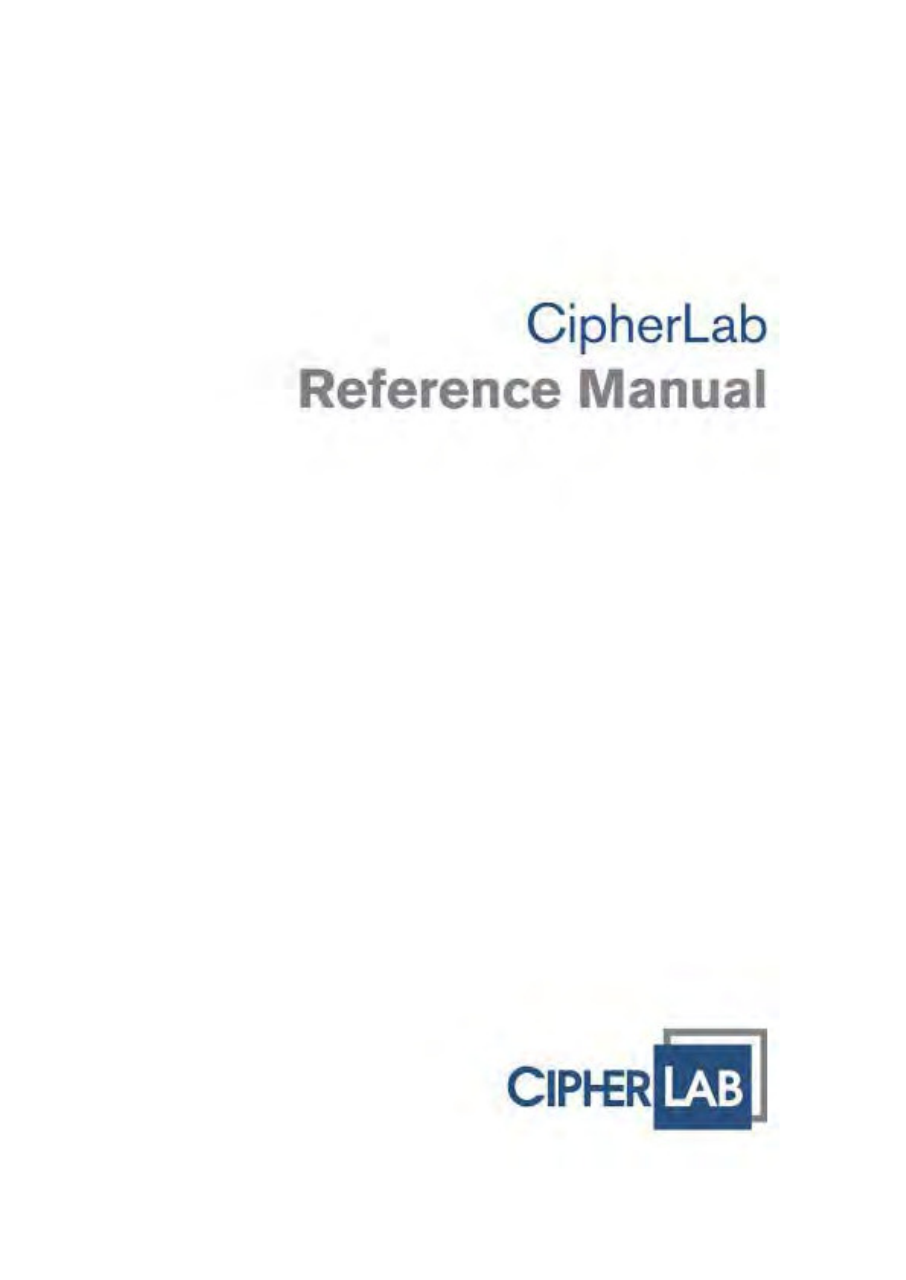
N o. De scr ipt ion N o. Descript ion
1 Receiver 2 St atus LEDs for scanner good read ( left) and
batt ery charging (right)
3 Touch Screen 4 Volum e Butt ons
5 Side Triggers, user-definable 6 Power Key
7 Scan Key, user-definable 8 Reset But ton
9 Bat tery Cover 10 Bat t er y Cover Latch
QUICK START

4
9200 Mobile Comput e
r
Ref erence Manual
11 Speaker 12 Charging and Com m unicat ion Port
13 Microphone 14 Digit al Cam era
15 Scanning Window 16 St ylus Slot
17 Headset Jack 18 Applicat ion Key, user- definable
5
Quick St art
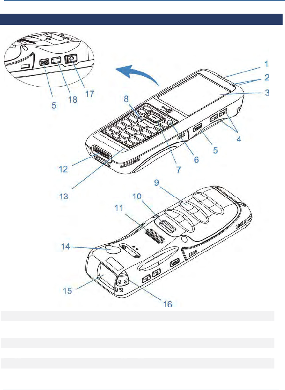
INSTALLING BATTERY
For shipping and storage purposes, the m obile com puter and t he m ain bat t ery are saved
in separate packages.
Note: Any im proper handling m ay reduce the bat t ery life.
1 . Push down t he clip on top of t he bat t ery cover to unlock it .
2 . Lift up and rem ove the bat tery cover.
3 . I nsert t he bat t ery pack int o t he battery com part m ent at a proper angle (30° ~ 45° )
wit h t he bat t ery cont act pins facing to the right .
4 . Press the battery down int o place. Make sure t hat the bat t ery is snugly fit into the
com part m ent.
5 . Replace t he battery cover. Fix the lower end first , t hen pull down t he clip on top
and press bat t ery cover in until a ‘click’ is heard. Lock bat t ery cover by pushing up
the clip.ʳʳ
Warning:
( 1) Check t hat t he clip on t op of the bat t ery cover is at t he “ lock” posit ion before
powering on the device.
( 2) For initial use, insert a charged bat t ery, secure the bat t ery cover in place, t hen
press the Power key t o power on the m obile com puter.
6
9200 Mobile Comput e
r
Ref erence Manual
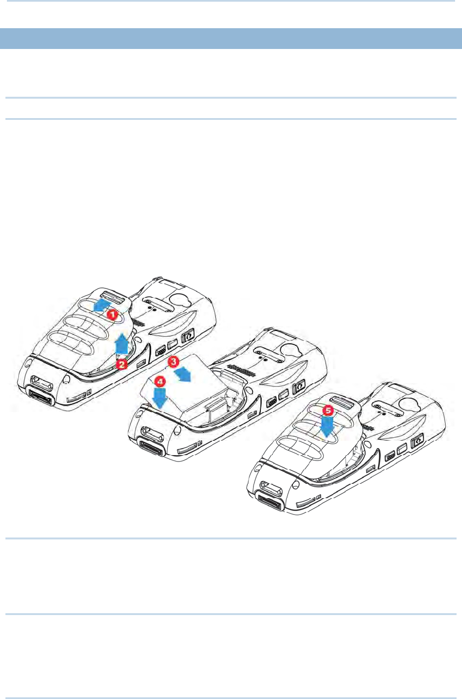
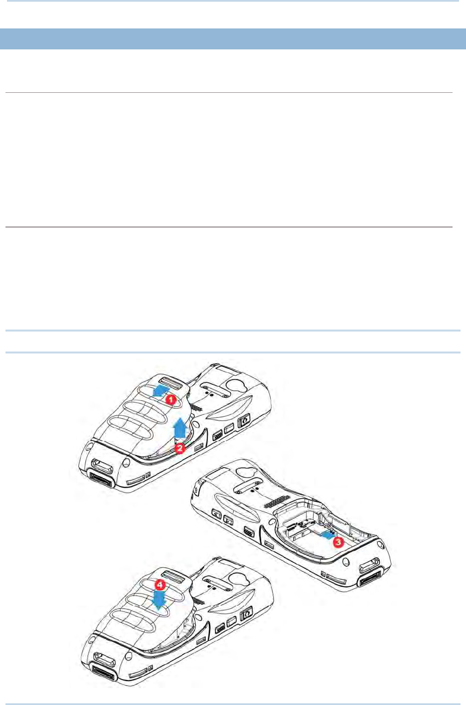
INSERTING SIM CARD
Inserting Card
1 . Push down t he clip on top of t he bat t ery cover to unlock it .
2 . Rem ove the battery cover as well as the bat t ery.
3 . I nsert SI M card int o t he SI M card slot as the icon engraved in t he battery
com part m ent shows. Push SI M card to lock it in.
4 . Replace t he battery cover. Fix the lower end first , t hen pull down t he clip on top
and press bat t ery cover in until a ‘click’ is heard. Lock bat t ery cover by pushing up
the clip.
Removing Card
1 . Push down t he clip on top of t he bat t ery cover to unlock it .
2 . Rem ove the battery cover as well as the bat t ery.
3 . Push the SI M card. I t will be ej ected aut om at ically for rem oval.
4 . Replace t he battery cover. Fix the lower end first , t hen pull down t he clip on top
and press bat t ery cover in until a ‘click’ is heard. Lock bat t ery cover by pushing up
the clip.
7
Quick St art
USING MEMORY CARD
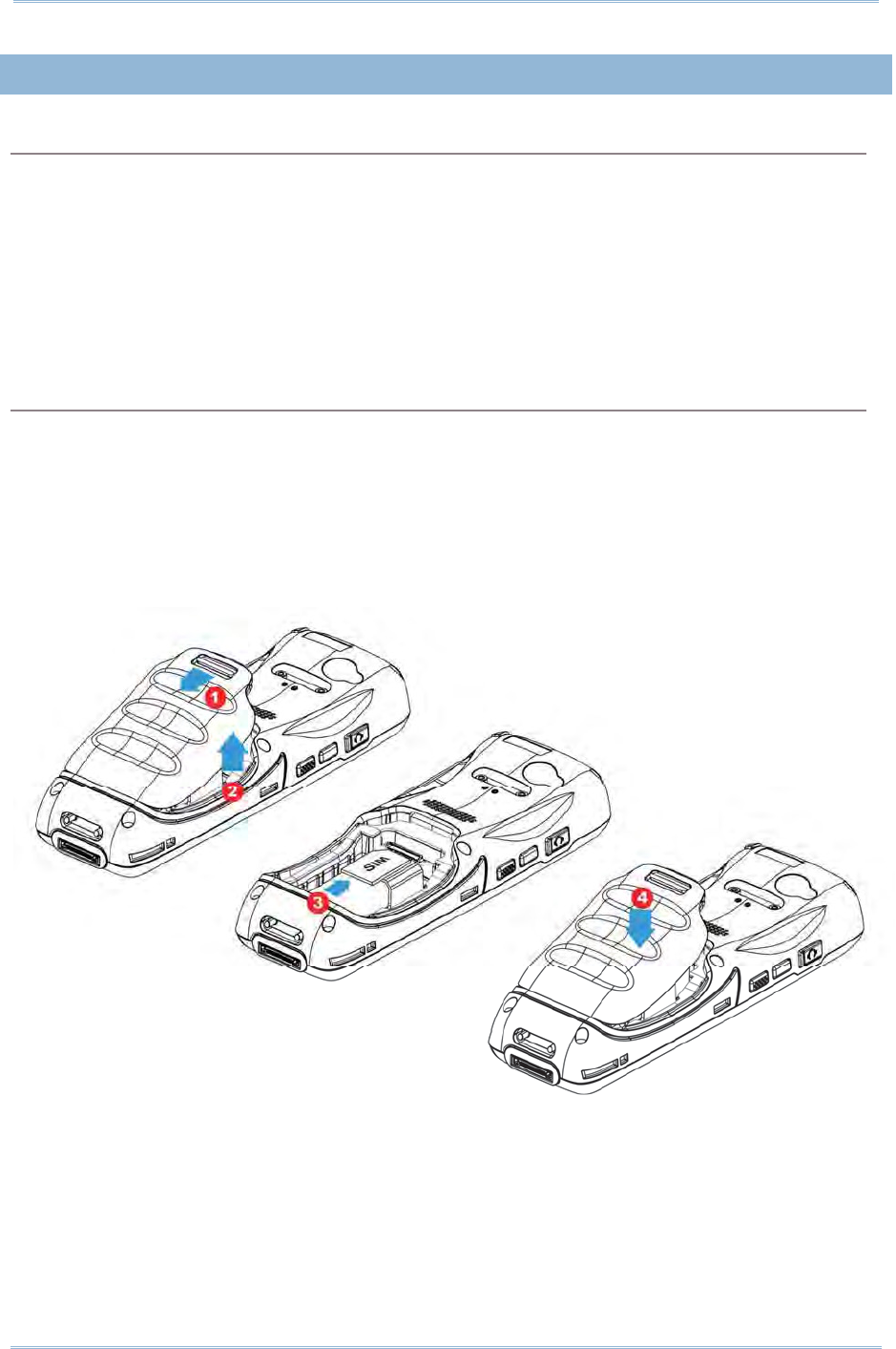
The m icoSD card slot is locat ed at the t op of the bat t ery com part m ent .
Inserting Card
1 . Push down t he clip on top of t he bat t ery cover to unlock it .
2 . Rem ove the battery cover as well as the bat t ery.
3 . I nsert m em ory card into the m icoSD card slot as the icon engraved in t he bat tery
com part m ent shows. Push m icroSD card to lock it in.
4 . Replace t he battery cover. Fix the lower end first , t hen pull down t he clip on top
and press bat t ery cover in until a ‘click’ is heard. Lock bat t ery cover by pushing up
the clip.
Removing Card
1 . Push down t he clip on top of t he bat t ery cover to unlock it .
2 . Rem ove the battery cover as well as the bat t ery.
3 . Push the m em ory card. I t will be ej ected aut om at ically for rem oval.
4 . Replace t he battery cover. Fix the lower end first , t hen pull down t he clip on top
and press bat t ery cover in until a ‘click’ is heard. Lock bat t ery cover by pushing up
the clip.
Note: We suggest using Toshiba and SanDisk class 4 card t ypes.
8
9200 Mobile Comput e
r
Ref erence Manual
POWER ON/ OFF MOBILE COMPUTER
POWER ON
To power on the m obile com puter, press and hold t he power but t on located on t he
upper right of t he keypad. The m obile com puter opens t o show t he Hom e Screen.
Note: For the m obile com puter to power on, t he batt ery cover m ust be secured in place.
POWER OFF
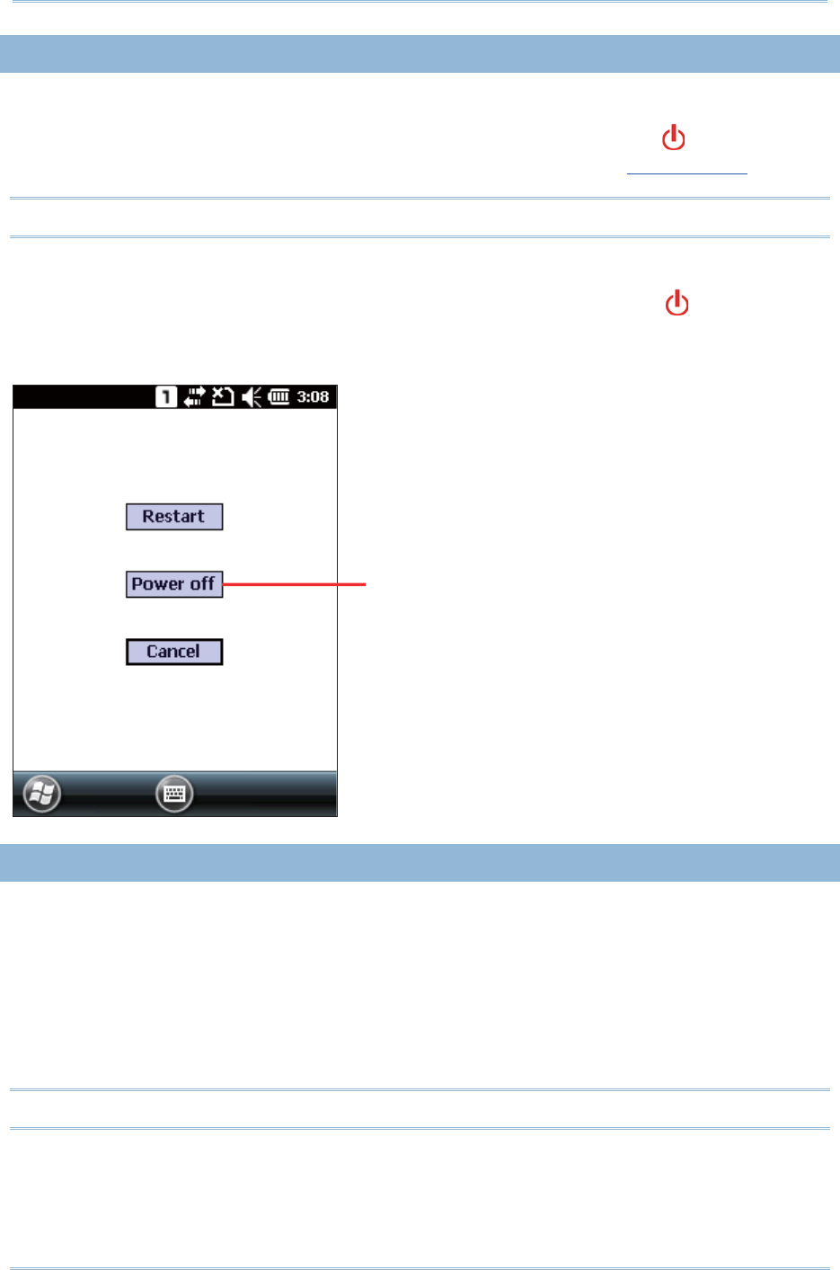
To power off t he m obile com puter, press and hold the power but t on for m ore than
three seconds. A m enu will appear on- screen to allow select ion bet ween rest art and
power off. Make sure all user dat a and tasks have been stored before tapping Pow er off.
CONNECTING HEADSET
The headset jack is located on t he left side of the m obile com puter. You can use the
headset for audio playback or com m unication via t he phone applicat ion, audio inst ant
m essaging, etc.
1 . Flip up t he rubber cover.
2 . Connect the headset to t he headset j ack.
3 . Replace t he rubber cover.
Note: Make sure you use a headset that follows t he CTI A standard.
Tap t o pow er off the
m obile com puter

9
Quick St art
CHARGING & COMMUNICATION
The m ain bat t ery m ay not be charged to full for shipm ent . When you first receive the kit
package, you will need to charge t he m ain bat t ery to full before using t he m obile
com puter. You m ay use t he Snap-on Cable or Charging & Com m unication Cradle along
with a power adapt er t o charge the m obile com puter.
Charging Time
Main bat t ery: I t takes approxim at ely 4 hours to charge an em pty bat t ery to full. The
charging LED above t he screen ( locat ed on t he right ) will light up in red while
charging and will t urn green when charging is done.
When the m ain battery is rem oved, RTC ret ent ion will be m aintained.
Charging Temperature
I t is recom m ended t o charge t he battery at room tem perat ure (18° C t o 25° C) for
optim al perform ance.
Batt ery charging stops when the tem perat ure drops below 0° C or exceeds 45° C.
Operation on Battery Power
When 802.11b/ g, GSM/ GPRS, and Bluet ooth are all enabled on bat t ery power, t he
m ain bat t ery charge will drop down subst ant ially.
I n order to prevent syst em shut down after the bat t ery is drained out , we suggest
that you keep a fresh batt ery for replacem ent at all t im es or connect the m obile
com puter to an external power.
USING WIRELESS NETWORKS
The m obile com puter supports widely applied wireless t echnologies, Bluet ooth and
802.11b/ g, and is able to send/ receive data in real t im e in an efficient way. Select
GSM/ GPRS m odules em bedded for a t otal wireless solut ion for data and voice
com m unication.
10
9200 Mobile Comput e
r
Ref erence Manual
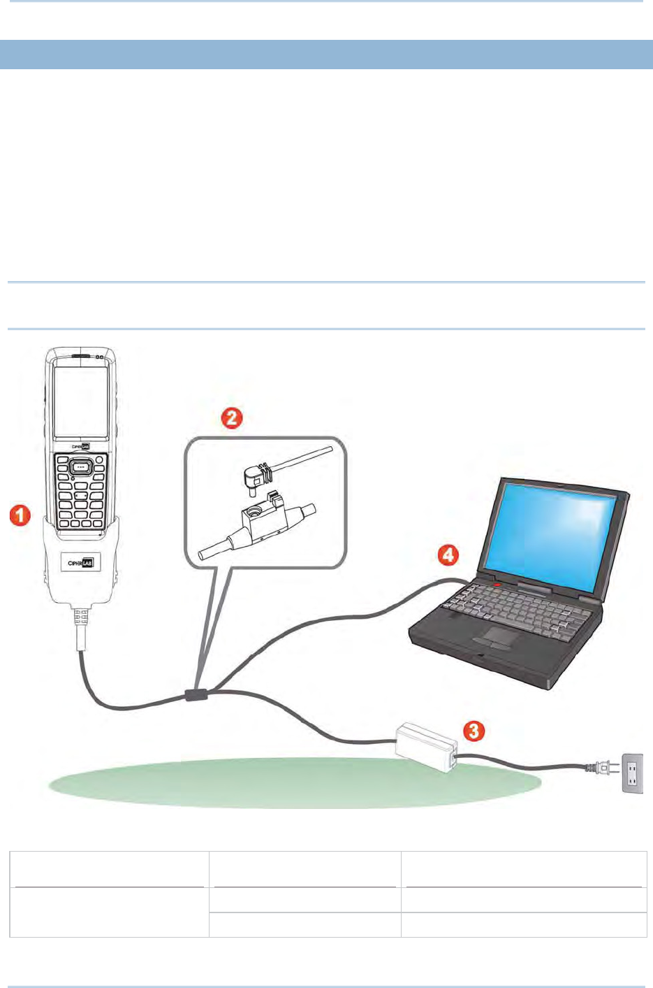
USING SNAP-ON CABLE
1 . Fast en the Snap- on Charging and Com m unicat ion Cable t o t he lower end of t he
m obile com puter.
2 . I nsert t he adapt er DC plug into the power j ack on the Snap-on Cable.
3 . Connect one end of t he power cord t o t he adapt or, and t he ot her end t o an
electrical outlet . ( Use power cord suitable for your count ry.)
The charging LED (left) on t he m obile com puter lights red while charging. The LED
will t urn green when charging is com plet ed.
4 . I f necessary, connect the USB/ RS- 232 end of t he cable t o your PC for data
transm ission.
Note: You m ay connect the Snap- on Cable to your PC for sim ult aneous dat a
com m unication and charging.
9200 LED Indicator Status Description
Red, solid Charging t he m obile com puter Charging
Green, solid Charging com plet e
11
Quick St art
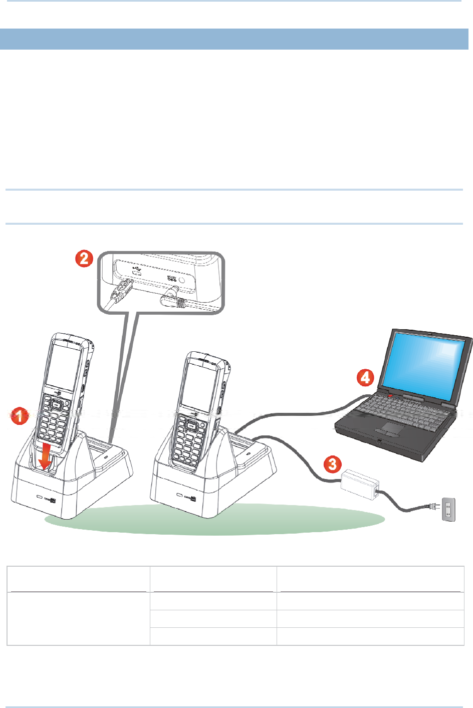
USING CRADLE
1 . Seat t he m obile com puter on the Charging and Com m unicat ion Cradle.
2 . I nsert t he adapt er DC plug into the power jack on the back of the Cradle.
3 . Connect one end of t he power cord t o t he adapt or, and t he ot her end t o an
electrical outlet . ( Use power cord suitable for your count ry.)
The charging LED (left) on t he m obile com puter lights red while charging. The LED
will t urn green when charging is com plet ed.
4 . I f necessary, connect t he Cradle and your PC with t he USB cable provided for data
transm ission.
Note: You m ay connect t he Charging & Com m unication Cradle t o your PC for
sim ult aneous data com m unicat ion and charging.
9200 LED Indicator Status Description
Red, solid Charging t he m obile com puter
Green, solid Charging com plet e
Charging
Red, blinking ( 2s: 2s) Charging error

12
9200 Mobile Comput e
r
Ref erence Manual

13
This chapter explains the features and usage of the m obile com puter.
IN THIS CHAPTER
1.1ʳBattery ..................................................................... 14
1.2ʳMemory .................................................................... 17
1.3ʳKeypad..................................................................... 18
1.4ʳTouch Screen ............................................................ 22
1.5ʳNotifications .............................................................. 25
1.6ʳDat a Capt ure............................................................. 28
Chapter 1
USING THE 9200 MOBILE COMPUTER

14
9200 Mobile Comput e
r
Ref erence Manual
1.1. BATTERY
Main Bat tery
The m obile com puter is powered by a rechargeable 3.7 V/ 3300m Ah Li-ion battery
pack, and it t akes approxim at ely 4 hours to charge it to full from the power adaptor
or approx. 8 hours using the Snap-on Cable ( at 500m A). However, t he charging t im e
m ay vary by working condition.
Spare Bat tery
A spare batt ery is provided as an accessory. We recom m end keeping a fully charged
spare bat t ery at hand in order t o replace the m ain bat tery when it is nearly drained
out .
Warning:
( 1) The bat t ery cover m ust be secured in position. I f not , the m obile com puter cannot
turn on by pressing t he power key or wake up by pressing the scan key.
( 2) For a new batt ery, m ake sure it is fully charged before using. Always prepare a
spare bat t ery pack, especially when you are on t he road.
15
Chapt er 1 Using t he 9200 Mobile Comput e
r
1.1. 1. BATTERY STATUS INDICATIONS
The bat t ery pack is the only power source for t he m obile com put er to w ork. Therefore,
when the m ain battery level goes low, you need to replace the bat t ery pack wit h a
charged one or charge it as soon as possible. Most of all, you should backup im port ant
data on a regular basis.
By looking at the bat tery status icon, you can t ell the bat t ery level rem aining in the m ain
battery – the m ore t he white bars, the m ore power in the m ain battery. Tap t he top of
the screen to expand t he tit le bar pull- down list, and t hen tap t he bat t ery icon to quickly
access t he Power Set t ings. Refer to Tit le Bar Drop-down List.
Alternatively, you m ay go t o Star t Scre en | Se t t in gs, and tap Pow er .
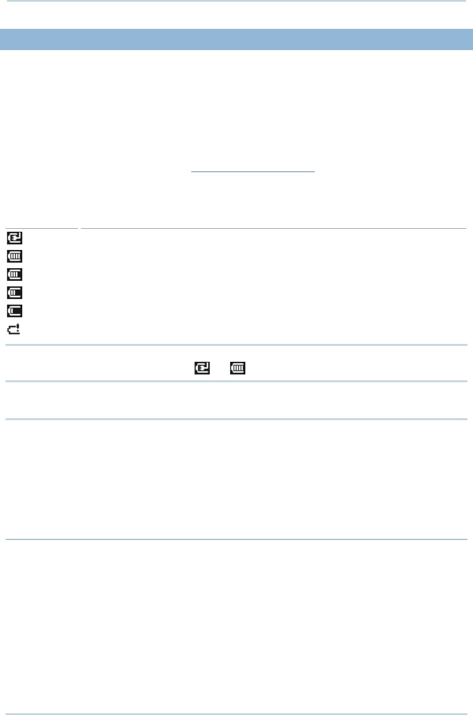
Battery Icon Description
Ext ernal power source is connect ed and m ain bat tery is charging.
Main batt ery level is 80% ~ 100% .
Main bat tery level is 60% ~ 79% .
Main bat tery level is 40% ~ 59% .
Main bat tery level is 20% ~ 39% .
Main bat tery level is very low (0% ~ 19% ) and needs charging im m ediately.
Note: When t he m obile com puter is fully charged and battery level reaches 100% , t he
battery icon will change from to .
Warning:
( 1) Once t he battery charge drops below 20% , t he low battery not ificat ion will be
displayed on t he screen.
( 2) Dat a loss m ay occur with RAM during low batt ery condit ion. Always save dat a
before battery runs out of power or keep a fresh battery for replacem ent .
( 3) Const ant usage of t he m obile com puter at low batt ery level can affect bat t ery life.
For m axim um perform ance, recharge the bat t ery periodically t o avoid battery
drain out and m aint ain good battery healt h.
16
9200 Mobile Comput e
r
Ref erence Manual
1.1. 2. POWER MANAGEMENT
For any port able device, power m anagem ent is a critical issue especially when you are on
the road. Below are som e tips to help you save battery power.
Warning: Using backlight, wireless connectivity, and peripheral devices while on
battery power will subst ant ially reduce batt ery power.
Bring a second bat t ery pack on the road.
End wireless connect ions such as Bluet ooth, 802.11b/ g or GSM/ GPRS which are not in
use.
Shorten the Backlight t urn off tim e, go to St art Screen | Settings | Syst e m , and
tap Scr een Ba ck light . Refer t o Adj ust LCD Backlight.
Disable key light funct ion, go to Sta rt Scr een | Settings | Sy st em , and t ap Keypad
Backlight t o select Alw ays Off to disable keypad Backlight funct ion.
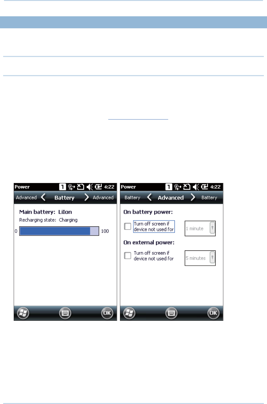
Go to Star t Scre en | Se t t in gs, and tap Pow er .
I n t he Bat t ery tab, you m ay m onit or the charging st at us.
I n t he Adva nced t ab, you m ay specify aut om at ic turn-off tim es for the m obile
com puter to conserve power. When t he screen is turned off, the system is in st andby
m ode, m eaning it is ready for use but not in use.

17
Chapt er 1 Using t he 9200 Mobile Comput e
r
1.2. MEMORY
Flash Mem ory (ROM)
512 MB flash m em ory for storing OS (Windows Em bedded Handheld 6.5) and cust om
applicat ion program s. Yet a portion of t he m em ory is referred t o as Flash Disk ( folder),
which can store dat a and program s that you wish to ret ain even aft er hardware reset .
Random - access Mem ory (RAM)
256 MB RAM for storing and running program s, as well as storing program data.
Expansion Slot
The m obile com puter is equipped with one m icroSD card slot, which is user accessible.
High capacit y m em ory card ( m icroSDHC) is supported.
1.2. 1. CAUTION OF DATA LOSS
When the m ain bat tery is rem oved or drained, only the contents of RTC will be ret ained.
All ot her unsaved dat a will be lost . To prevent t his situation, always save your dat a and
pay at tention to rem aining battery level.
If you want to put away the mobile computer for a couple of days, you should be aware
that dat a loss occurs when the m ain bat t ery discharges com plet ely. Therefore, it is
necessary t o backup dat a and files before putt ing away the m obile com puter!
1.2. 2. CHECK STORAGE SPACE
Go to St art Scre en | Se t t ings | Sy st e m , and t ap Mem ory. I t displays t he current
capacit y and usage of t he onboard RAM.
St orage m em ory refers to the m em ory allocated for file and dat a st orage.
Program m em ory refers to the m em ory allocat ed for running program s.
Also, it provides inform at ion on the Flash Disk folder or storage card. The Flash Disk
folder is part of the onboard 512 MB flash m em ory. Because the flash m em ory is
non- volat ile, data or program s stored in t his folder will not be erased aft er hardware
reset.
18
9200 Mobile Comput e
r
Ref erence Manual
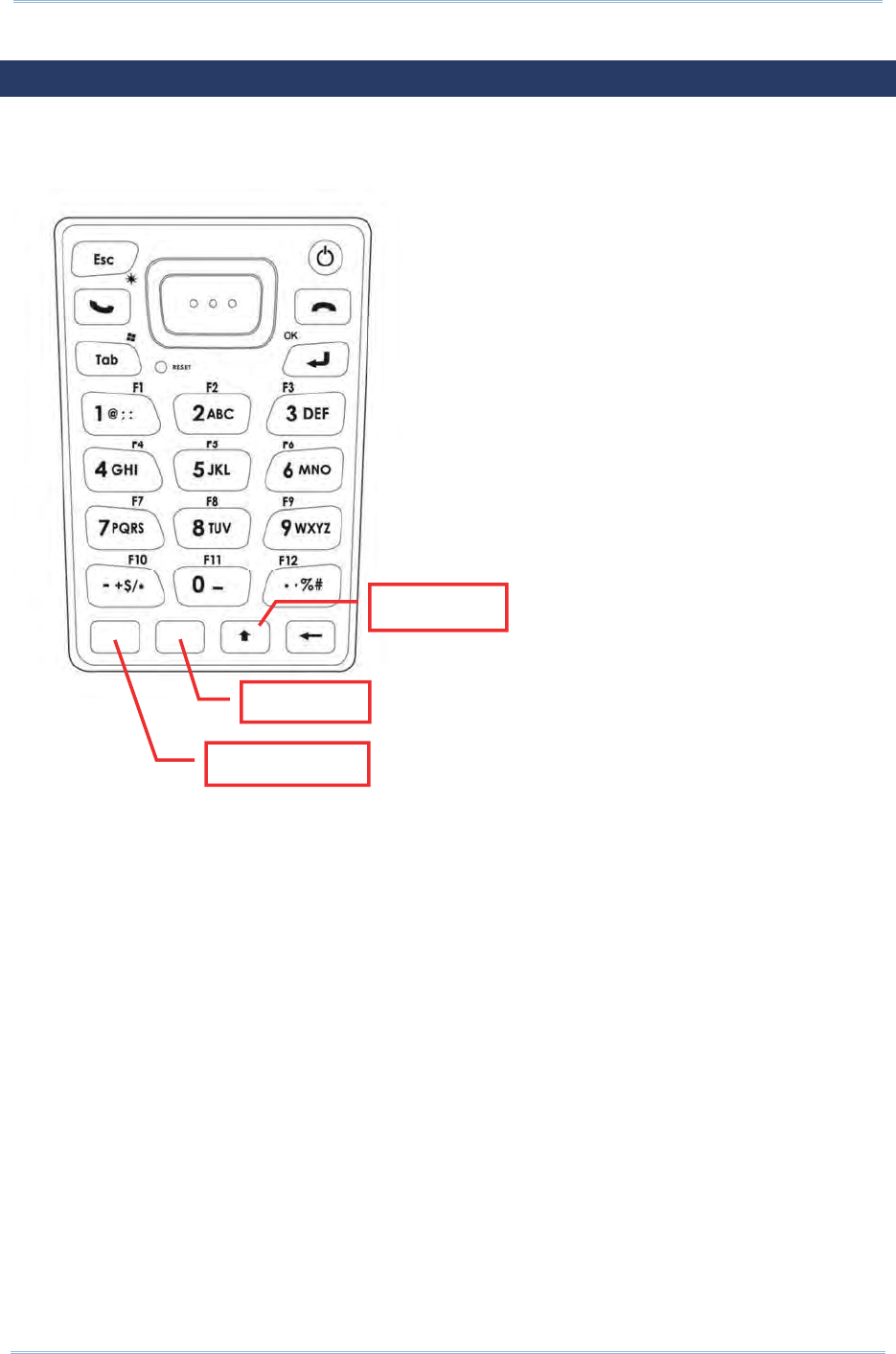
1.3. KEYPAD
The Alphanum eric keypad includes alphanum eric, call/ end keys, navigation keys, funct ion
keys, and so on. This keypad is set to num eric m ode by default.
Al
p
ha ke
y
Funct ion key
Shift key
19
Chapt er 1 Using t he 9200 Mobile Comput e
r
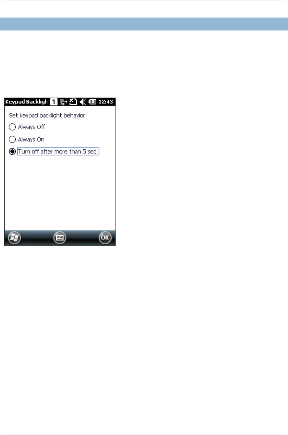
1.3. 1. KEYPAD SETTINGS
Go to Start Scre en | Se t t ings | Syst e m , and tap Keypad Ba cklight to configure
related settings.
The keypad backlight is set to be autom at ically turned on for 5 seconds when any key is
pressed. Alt ernatively you m ay have it always turned off or turned on instead. I t is
suggest ed to turn on the keypad backlight while working in a dark area; however, using
backlight while on bat t ery power will subst ant ially reduce battery power.
20
9200 Mobile Comput e
r
Ref erence Manual
1.3. 2. ALPHA KEY
This alphanum eric keypad is set to num eric m ode by default . The Alpha key [ Į] serves as
a swit ch key bet ween num eric and alpha (lower-case alphabetic) input m odes.
Note: Press [ Į] key to switch bet ween num eric and lower-case alphabetic m odes.
The alpha icon will appear on the stat us bar with a sequence as shown below.
Status Icon Alpha Key Input Mode
- - - Num bers
Press [ Į] one tim e Lower-case alphabetic charact ers
Note:
( 1) Under m ode, use the Shift key [ ×] t o ent er ALPHA ( upper-case alphabetic)
character ( or ) m ode.
( 2) I f you are using the on- screen keyboard, t ap CAP (Caps Lock) to switch
upper-case and lower-case alphabetic m odes.
1.3. 3. SHIFT KEY
Status Icon Shift Key Input Mode
Ш
Ш
Press [ ×] one tim e The Shift key [ ×] m odifies the next key pressed
depending on the input m ode.
( 1) I n num eric m ode ( ) , it will m odify t he next key
pressed.
( 2) I n alpha (lower- case alphabetic) m ode ( ), it will
show a single upper- case charact er aft er pressing Shift
key [ ×] one tim e.
For exam ple, input “ ABC”, it w ill show “ Abc.
Ш
Ш
Press [ ×] two tim es
( ent er Shift Lock Mode)
Pressing Shift key [ ×] t wo tim es will lock the present input
m ode.
( 1) I n num eric m ode ( ), it will lock num eric m ode.
( 2) I n alpha (lower- case alphabetic) m ode ( ), it will
lock upper-case alphabetic m ode ( = Caps Lock) .
For exam ple, input “ ABC”, it will show “ ABC”.
Note: I t is not necessary t o long press the Shift key [ ×] .

21
Chapt er 1 Using t he 9200 Mobile Comput e
r
1.3. 4. FUNCTION KEY
The Funct ion key [ Fn] serves as a specified key, and the functionality of each key
com binat ion is applicat ion- dependent .
1) To enable this special key, press [ Fn] on the keypad. I t s icon will appear on t he
st at us bar.
2) Now press anot her key to get t he value of key com binat ion ( say, press [ 1] to get the
value of F1) .
3) To get the value of anot her key com binat ion specified by t he funct ion key, repeat
st ep 2.
4) To disable the special key funct ion, press [ Fn] again, and the icon will go off.
Note: I t is not necessary t o long press the [ Fn] key.
The default [ Fn] key com binations are defined as below:
Key Combination Action
[ Fn] , [ 1] = F1 Soft key 1
[ Fn] , [ 2] = F2 Soft key 2
[ Fn] , [ 3] = F3 Talk
[ Fn] , [ 4] = F4 Minim ize current active window
[ Fn] , [ 5] = F5 n/ a
[ Fn] , [ 6] = F6 Volum e Up
[ Fn] , [ 7] = F7 Volum e Dow n
[ Fn] , [ 8] = F8 *
[ Fn] , [ 9] = F9 #
[ Fn] , [ 0] = F10 Record
Note: Press the [ Fn] key first , and t hen press the second key for a specific funct ion.
1.3. 5. PROGRAMMABLE KEYS
The following keys are user- definable. They can be defined t o serve as anot her key or to
serve as a shortcut to launch a specific program . See Button Assignm ent ut ilit y for m ore
details.
Two side triggers
Application key
[ -] ( Hyphen key)
[ .] ( Period key)
22
9200 Mobile Comput e
r
Ref erence Manual
1.4. TOUCH SCREEN
The m obile com puter com es wit h a 2.8” TFT graphic LCD, 240 by 320 pixels resolut ion
( QVGA) . The LED backlight of screen, which helps ease reading under dim environm ent s,
can be cont rolled m anually and autom at ically.
Warning: Using backlight while on battery power will subst ant ially reduce battery
power. I t is suggested t o dim the backlight while working in a well-lit area
or autom at ically turn off t he m obile com puter when not in use.
1.4. 1. ADJUST LCD BACKLIGHT
Go to St art Screen | Settings | Sy st em , and tap Scree n Ba ck ligh t to configure
related settings. I n t he Backlight / Ext ernal Power configuration screen, you can select the
Turn off backlight if de vice is n ot used for check box to disable t he backlight function,
and select the tim e from t he related drop- down list to cont rol t he backlight disabled tim e.
You can also set the backlight brightness by dragging t he slider to the right ( for
brightness increase) or left ( for brightness decrease) .
23
Chapt er 1 Using t he 9200 Mobile Comput e
r
1.4. 2. SCREEN SETTINGS
The LCD is also a t ouch screen that can be calibrated t hrough screen alignm ent .
Go to Start Scre en | Se t t ings | Syst em , and t ap Scre en t o configure relat ed set t ings.
You m ay re-calibrat e the touch screen, sm ooth t he font edges or adj ust the t ext size
displayed on t he screen if necessary.
Warning: DO NOT use any point ed or sharp object s t o m ove against t he surface of
the screen.
24
9200 Mobile Comput e
r
Ref erence Manual
1.4. 3. CALIBRATION
The m obile com puter’s t ouchscreen needs t o be calibrat ed after a period of use t o ensure
it s accuracy. Calibration will align a set of coordinat es on t he touch panel and LCD
underneath.
Tap Se t t in gs | Syst e m | Screen to open the Alignm ent t abbed page. Tap Align Screen
to st art t ouchscreen calibrat ion. Use t he stylus to t ap the crosshairs one by one to
perform calibrat ion.
When calibrat ion is com pleted, t he alignm ent screen will close.

25
Chapt er 1 Using t he 9200 Mobile Comput e
r
1.5. NOTIFICATIONS
1.5. 1. STATUS LED
Two LED indicators locat ed above t he touch screen provide inform at ion about charging
st at us, scanner light beam , and scanner " Good Read" during data collection.
LED Indicators Status Description
Green, solid Charging com plet e
Red, solid Charging t he m obile com puter
Charging
Red, solid for 8 sec, t hen
flashing
Charging error ( for instance,
batt ery not in place)
Left
Scanner decode Green, flash once Good read
Right Scanner beam
Orange, on while scan key
is pressed Scanner laser beam sent out
Note: For Scanner decode and Scanner beam LED t o funct ion, LED notificat ion m ust be
enabled in Reader Configurat ion. See Enable LED Not ificat ion.
1.5. 2. AUDIO
The speaker is used t o play sounds for events in Windows and program s, or play audio
files such as .WAV files. I n addit ion, it can be program m ed for st at us feedback. I n noisy
environm ent s, you m ay consider connect ing a CTI A headset inst ead. A headset jack is
provided on t he left side of t he m obile com puter, which is a 3.5 m m DI A st ereo earphone
j ack. The m obile com puter also support s using Bluet ooth headsets.
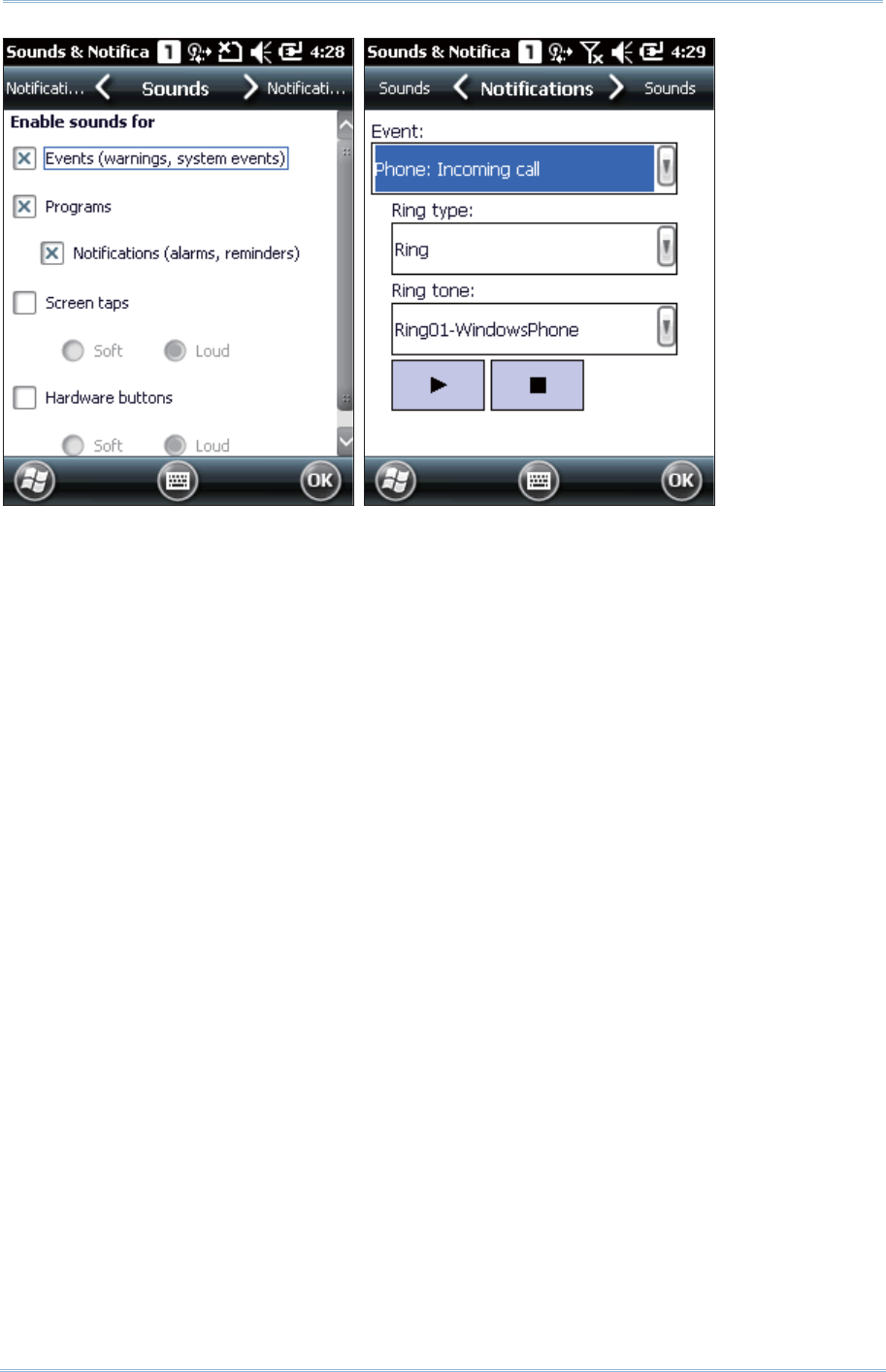
Go to Star t Scre en | Set t ings, and tap Sounds & Notifica t ions t o configure relat ed
set t ings.
26
9200 Mobile Comput e
r
Ref erence Manual
27
Chapt er 1 Using t he 9200 Mobile Comput e
r
1.5. 3. VIBRATOR
The m obile com puter is integrat ed wit h a vibrat or, which is soft ware program m able for
tact ile feedback. This can be helpful when working in noisy environm ent s.
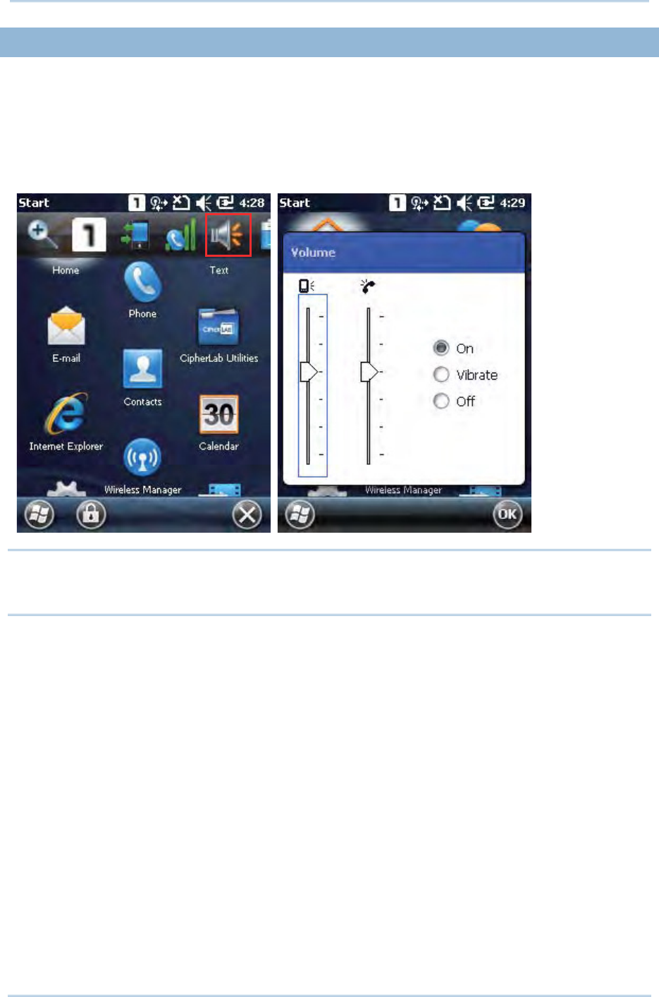
Tap the t op of the screen to invoke the t it le bar drop- down list , and then t ap the volum e
set t ing icon t o change t he syst em volum e or phone ringing volum e. You m ay m ute it or
have it set to vibrat e instead.
Note: You m ay switch t he volum e settings between On, Vibrat e and Off in the Volum e
control screen. The volum e adj ustm ent slider bar is only available for adj ustm ent
in volum e “On” m ode.

28
9200 Mobile Comput e
r
Ref erence Manual
1.6. DATA CAPTURE
1.6. 1. BARCODE READER
A selection of scan engines is available for delivering flexibility to m eet different
requirem ent s. Depending on t he scan engine int egrat ed, the m obile com puter is capable
of scanning barcodes of a num ber of sym bologies t hat are enabled by default while
running the ReaderConfig.exe utility. I f you need to scan barcodes that are encoded in a
different sym bology, enable t he sym bology first.
1.6. 2. RFID READER
By selection, t he m obile com puter provides an RFI D reader for decoding RFI D t ags. To
ready t heʳm obile com puter to read such tags, select t he RFI D label in the Reader
Configurat ion Ut ilit y.
1.6. 3. DIGITAL CAMERA
An int egrat ed 3.0 m egapixel CMOS cam era in the m obile com puter is specifically
designed for collect ing im age data. We provide an im age capture utility that is specifically
designed to turn on t he cam era and capture im ages.
29
Chapt er 1 Using t he 9200 Mobile Comput e
r
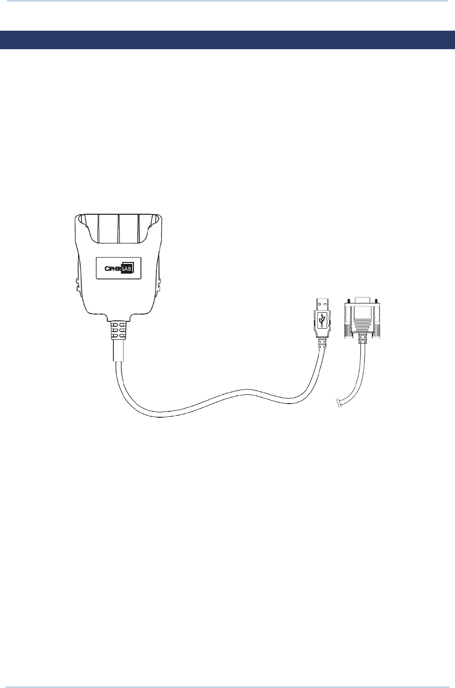
1.7. SNAP-ON CHARGING & COMMUNICATION CABLE
The Snap-on Charging & Com m unication Cable provides a convenient way t o charge your
m obile com puter and also connect it to your PC.
Slide and “ click” to attach; press release but t ons and pull to detach
Connect s t he m obile com puter and PC t hrough USB or RS- 232
Provides DC adapter j ack on cable for charging the m obile com puter
Com plet es charging in approxim at ely 8 hours
LED on m obile com puter shows charging status
Adapter input 100- 240VAC, 50/ 60Hz; out put 5VDC/ 4A
30
9200 Mobile Comput e
r
Ref erence Manual
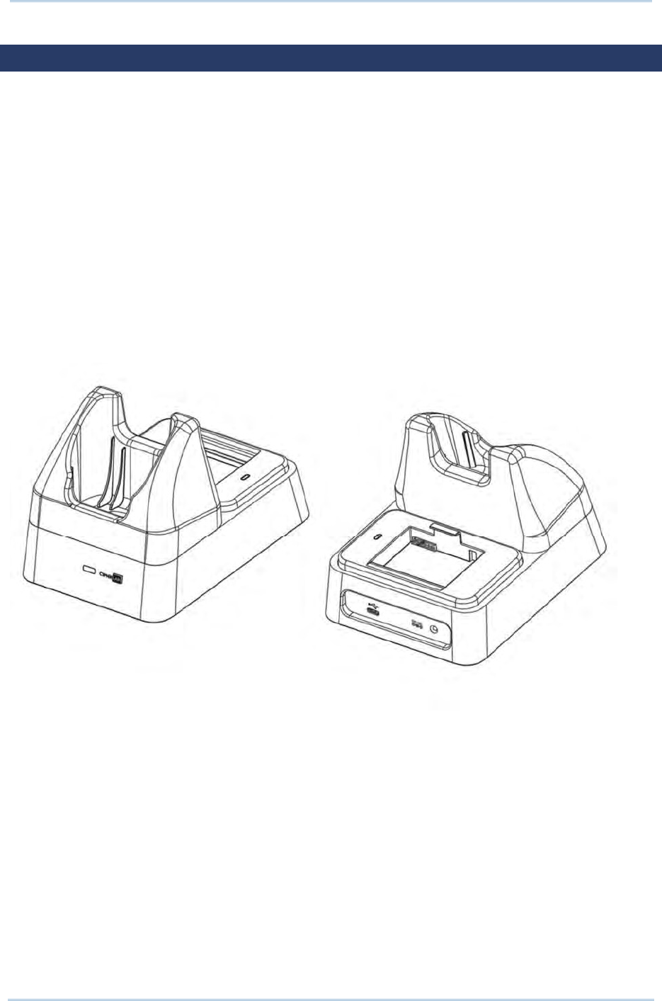
1.8. CHARGING & COMMUNICATION CRADLE
The Charging & Com m unicat ion Cradle charges your m obile com puter and a spare
battery at the sam e tim e. You m ay also use the cradle for dat a t ransm ission bet ween
your PC.
Present s charging com part m ent for m obile com puter and spare battery
Provides m icroUSB socket on t he back for dat a transm ission with PC
Support s USB Host Mode via a USB OTG cable
Provides DC adapter j ack on t he back for charging t he m obile com puter
Com plet es charging in approxim at ely 4 hours
Front LED shows charging status for m obile com puter
Side LED shows charging status for spare batt ery
Adapter input 100- 240VAC, 50/ 60Hz; out put 5VDC/ 3.3A

31
This chapter m ainly describes the basic skills to work with t he 9200 Mobile Com put er.
The add- on utilit ies for applicat ions regarding dat a collect ion, processing, and
transm ission, are int roduced in the following chapt ers.
The m obile com puter is specifically designed for real-tim e data collect ion in t he Windows
Em bedded Handheld 6.5 environm ent . I t won't t ake long for any Windows user t o get
fam iliarized wit h it . Keep t hese basic skills in m ind and explore t his Windows Em bedded
Handheld device at ease.
Tap an item t o select it.
Tap and hold an item to see a m enu that enables tasks, such as cut, copy, renam e,
delet e, etc.
Tap at the bot tom of the screen t o close an active window, a dialog box, or a
running application.
Tap at t he bottom of the screen to save t he current set t ings and exit t he
applicat ion ( or m inim ize t he window in som e applications) .
Tap at t he bot t om of the screen to return the previous m enu.
Tap at t he bott om of the screen to open t he St art Screen.
IN THIS CHAPTER
2.1ʳGetting Started.......................................................... 32
2.2ʳI nput Methods ........................................................... 40
2.3 Managing Programs ................................................... 41
2.4ʳUsing Act iveSync ....................................................... 44
2.5ʳSuspend & Reset........................................................ 48
Chapter 2
LEARNING WINDOWS EMBEDDED HANDHELD
BASICS
32
9200 Mobile Comput e
r
Ref erence Manual
2.1. GETTING STARTED
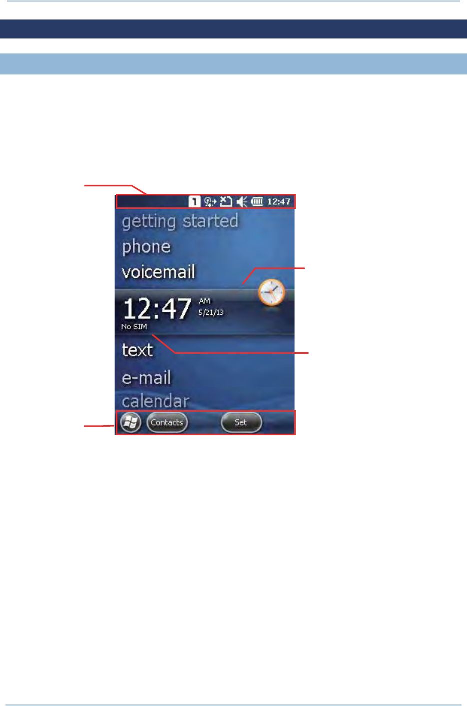
2.1. 1. HOME SCREEN
When the m obile com puter is fully charged, press the Power key for t hree seconds to
turn on the m obile com puter and wait for the H om e Scr ee n to com e up.
Scroll t he Hom e Scree n up and down t o highlight a desired applicat ion. The addit ional
inform at ion or it em s will appear sideways, and soft key bar will be available at the bott om
of the screen as well.
I f you are using the m obile com puter for the first tim e, there are a couple of things to do
after t he Hom e Scr een com es up. The Getting St arted wizard will walk you t hrough
e- m ail setup, changing t he background im age, etc.
Go to Star t Scre en | Se t t in gs, and tap H om e t o change t hem e, background, and
st at us it em s show n on the H om e Scre en, et c.
Go to Start Scre en | Se t t in gs, and tap Clock & Alar m s t o select tim e zone, change
local t im e, set alarm s, etc.
Tit le Bar
Soft key ba
r
A
pp
licat ion I nfo.
A
pp
licat ion I con
33
Chapt er 2 Learning Windows Embedded Handheld Basics
2.1. 2. TITLE BAR
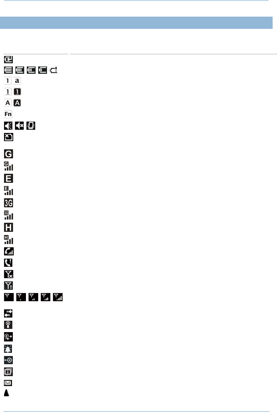
The icons at t he top of t he screen are explained below.
Icon Description
Ext ernal power source is connected.
Batt ery pow er rem aining: more bars indicate m ore power in t he batt ery.
Keypad is in default num eric m ode or alphabet ic m ode.
Shift [ ×] is enabled in num eric m ode/ num eric lock m ode.
Shift [ ×] is enabled in alpha m ode/ alpha lock m ode.
Funct ion m ode is enabled.
Volum e status: On, off, or vibrat e.
SI M card is m issing. You can still m ake em ergency calls if your service
provider supports it.
GPRS service available.
GPRS connect ion is established.
EDGE service available.
EDGE connect ion is est ablished.
UMTS (3G) service available.
UMTS (3G) connect ion is established.
HSPA service available.
HSPA connect ion is established.
I ncom ing call.
Missed call.
Antenna signal st atus: Phone power off.
Ant enna signal st atus: PI N Code required for power ing on the Phone.
Antenna signal st atus: phone power on; the m ore bars, the st ronger the
signal.
Connect ion is active.
Wi- Fi Net work is det ect ed ( but not connect ed) .
Wi- Fi Network is connect ed.
Rem inder for an alarm or appoint m ent is active.
Receiving Bluetooth beam s.
System not ification icon.
E- m ail/ text m essage is received.
Roam ing.
.
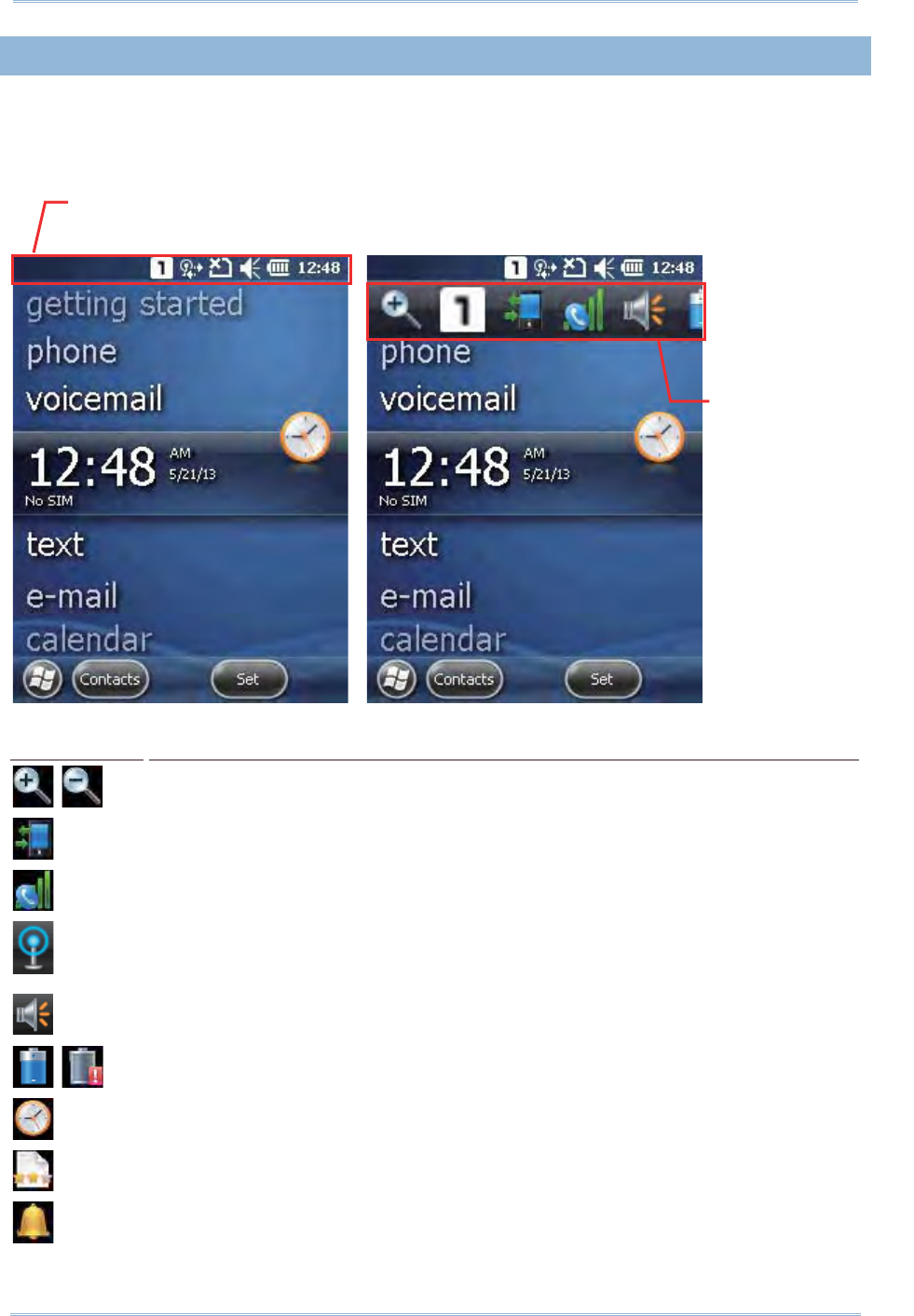
34
9200 Mobile Comput e
r
Ref erence Manual
2.1. 3. TITLE BAR DROP-DOWN LIST
The title bar drop-down list is hidden at the t op of the screen, and can be expanded by
tapping the title bar:
Icon Description
Tap it to zoom in or zoom out of current view.
Tap it to check the connect ions status. You m ay configure the set tings through
W ireless Manage r.
Tap it to check t he phone stat us. You m ay configure t he set tings t hrough
W ireless Manage r.
Tap it to show detect ed net works for Wireless local area networking ( WLAN)
connect ion, which is not available until Wi-Fi power is t urned on t hrough W ireless
Ma na ger .
Tap it to change t he syst em volum e. You m ay m ute it or have it set as vibrat e
inst ead.
Tap it to m onitor t he charging stat us and change the power schem e.
Tap it to change t he clock and alarm s settings.
Tap it to subm it cust om er feedback to Microsoft for im proving Windows Embedded
Handheld soft ware.
Tap it to view t he rem inder for an alarm or appointm ent .
Tap the t itle bar to reveal
the drop-dow n list.
Drag t he drop-down
list to left or right t o
view all t he icons.

35
Chapt er 2 Learning Windows Embedded Handheld Basics
Tap it to receive incom ing Bluetooth beam s.
Bluet oot h A2DP profile is in use. Tap it to access the Bluetooth devices list .
Tap it to view a m issed call.
Tap it to check a new e-m ail.
Tap it to check a new voicem ail.
Tap it to send an SMS text m essage.
Speakerphone is on.
Tap it to access the Bluet oot h configuration.
Tap it to configure Act iveSync connect ion sett ings.
Roam ing is on.
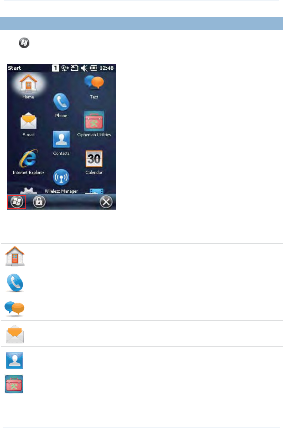
36
9200 Mobile Comput e
r
Ref erence Manual
2.1. 4. START SCREEN
Tap t o open the St a rt Scr een . You can t ap to access application program s and
useful ut ilit ies developed by CipherLab, or configure syst em set t ings.
The icons provided on the Start Screen are depict ed as follows:
Icon Name Description
Hom e (Today) Opens t he Hom e Screen.
Phone Launches the m obile com puter’s phone.
Text Sends SMS t ext m essages.
E- m ail Writ es and sends em ails.
Cont act s List all of your contact s, including e-m ail and inst ant
m essenger cont acts; sim ilar to t he phone book on a cell
phone.
CipherLab Ut ilities This folder cont ains m ore CipherLab- developed applicat ions
that ar e preinst alled on t he m obile com put er and which
st rengt hen the user’s system m anagem ent .
37
Chapt er 2 Learning Windows Embedded Handheld Basics
I nternet Explorer Browses world wide web.
Wireless Manager Quick sets the power for phone, Bluetooth and Wi- Fi, and
opens each of t he sett ings pages.
Calendar Creat es and m anages events, m eetings, and appoint m ents.
Set tings Accesses system set tings.
Gett ing Start ed Opens Get t ing St art ed application t o set OS basic feat ures.
Pict ures & Videos View s pictures and plays videos dow nloaded, copied or t aken
wit h t he built-in camera.
Cam era Takes pictures and shoot s videos.
Windows Media Plays audio/ video files.
Market place Not available; Market place for Mobile service was term inat ed
on 22nd May 2012.
Messenger Provides I M service.
Windows Live Accesses Windows Live ser vices (such as Hot m ail) or searches
world wide w eb.
MSN Weather Checks the weather of your locale and other part s of the
world.
Calculat or Perform s m athem at ical calculations.
Notes Creat es notes by typing on t he physical keypad or on-screen
keypad.
Tasks Creat es, tracks, and m anages t asks.
38
9200 Mobile Comput e
r
Ref erence Manual
Adobe Reader LE Browses PDF files.
File Explorer Browses and m anages the files on local storage.
ActiveSync Synchronizes Microsoft Office Outlook data between the m obile
com puter and anot her Windows- based com put er.
I nternet Sharing Shares t he m obile com put er’s m obile data connection with
another com puter t hrough a USB or RS-232 cable.
Task Manager Monit ors t he active applications and CPU/ m em ory usage on
the m obile com puter.
Search Phone Searches cont act s, files and ot her data on the m obile
com puter.
Help Accesses OS online help.
Rem ote Deskt op
Mobile
Connect s t o a rem ote com put er.
Alarm s Opens Clock & Alarm s applicat ion t o:
Set dat e, t im e, tim e zone for your locale.
Set and m anage alarm s.
Bing Opens search engine.
Confirm at ion for service agreem ent is needed before first
use.
MSN Money Checks st ocks.
Gam es Opens Window s Em bedded Handheld gam es.
39
Chapt er 2 Learning Windows Embedded Handheld Basics
2.1. 5. DEVICE LOCK
By default, t he device is unlocked. You m ay lock the m obile com puter to prevent
unint ended operation. When locked, it will not respond to screen touch or keypad input
until it is unlocked again. However, on the Lock screen you can still m onitor t he device
st at us on t he t it le bar. I f the Lock screen is enabled, the Volum e adj ust m ent keys on t he
left side will be unavailable.
Lock 9200
Open Star t Screen , and tap the lock icon on the soft key bar to prot ect your m obile
com puter.
Password Lock
You m ay further apply password prot ection t o block unauthorized access. Go t o Star t
Screen | Se t t in gs, and t ap Lock .
Sim ple PI N: Set up a password (4- digit at least )
St rong alphanum eric: Set up a st rong password ( 7- character at least)
Unlock 9200
Drag t he lock slide to left or right of t he unlock screen.
Note: For the Sim ple PI N password t o Lock screen, the password can not be a sequence
of num erals (e.g. 1111 or 1234), and cannot contain uppercase/ lowercase let t ers
or punct uat ion.
Tap to lock device.
Device is locked
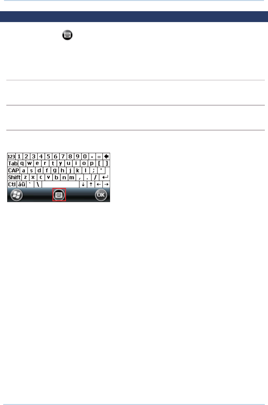
40
9200 Mobile Comput e
r
Ref erence Manual
2.2. INPUT METHODS
The keyboard icon at t he m iddle bottom of t he screen is for Soft ware I nput Panel
( SI P). Tap t he icon to show or hide the on- screen keyboard.
Dat a ent ry can be perform ed by the following m et hods.
Physical Keypad
Type wit h the physical keypad on the m obile com puter.
Data Capture
Scan barcode in applicat ions, e.g. Notes, Reader Config, etc.
Software Keypad
Type or writ e using SI P ( Soft I nput Panel):
Tap the SI P but t on on m iddle softkey bar to show or hide the input panel.

41
Chapt er 2 Learning Windows Embedded Handheld Basics
2.3. MANAGING PROGRAMS
Tap the St a rt button to open t he Star t Scre en. Tap a program to launch it . To add a
new program or subfolder t o t he Start Scree n, you can either use File Ex plore r on the
m obile com puter or Act ive Syn c on your PC. See Using ActiveSync for how to operate via
ActiveSync.
Warning: To avoid m aking any changes to the program configurations by accident ,
we recom m end you to use Copy and Paste Short cut rat her t han Cut and
Past e .
2.3. 1. ADD A PROGRAM TO START SCREEN
1 . Tap Sta r t Scr een | File Explorer .
2 . Navigat e to find t he program of int erest.
3 . Tap and hold t he program and select Copy from the pop- up m enu.
4 . Navigat e to the Program s folder – My Device\ W indow s\ St a r t Me nu\ Progr am s.
5 . Tap and hold any blank spot on the screen and select Past e Shortcut from t he
pop-up m enu. The new program will be added to the Program s folder.
6 . Open Star t Scre en. The newly added program will appear now.
2.3. 2. CREATE A NEW FOLDER
1 . Tap Sta r t Scr een | File Explorer .
2 . Navigat e to the location which you would like to create a new folder.
3 . Tap Menu | N ew Folde r and a subfolder will be creat ed.
OR
Tap and hold any blank spot on the screen and select New Folde r in t he pop-up
m enu.
2.3. 3. SWITCH BETWEEN ACTIVE PROGRAMS
1 . Tap Sta r t Scr een | Task Mana ger.
2 . Select which running program t o use.
3 . Tap Menu | Sw it ch To and t he program will be m axim ized on- screen
OR
Tap and hold t he program of int erest and select Sw it ch To in the pop- up m enu.
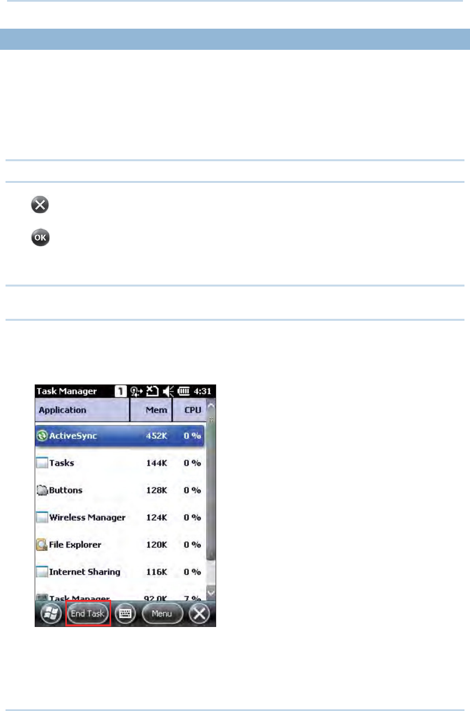
42
9200 Mobile Comput e
r
Ref erence Manual
2.3. 4. END A PROGRAM
I n general, the system m anages m em ory aut om atically, and t here is no need to exit a
program in order to open another or t o conserve m em ory. However, random access
m em ory ( RAM) m ay be used up w hen too m any program s are running sim ultaneously. As
a result , it will slow down syst em operat ion or cause program errors. I n this case, you
should exit one or m ore of t he running program s t o release m em ory. I n order to use
m em ory in a m ore efficient way, you are recom m ended t o exit a program once it is no
longer in use.
Warning: Always rem em ber to save dat a or settings before you exit a program .
Tap t o close an act ive window, a dialog box, or a running application.
Tap t o save t he current set t ings and exit the applicat ion (or m inim ize t he window in
som e applicat ions) . I f the but ton is not displayed on t he soft key bar, press OK on the
physical keypad.
Note: Som e program s com e with an associated icon on t he softkey bar. You m ay t ap the
icon and t ap End Task t o end the act ive program .
1 . Tap Sta r t Scr een | Task Mana ger.
2 . Select a running program to st op.
3 . Tap End Ta sk on the softkey bar and the program will be closed.
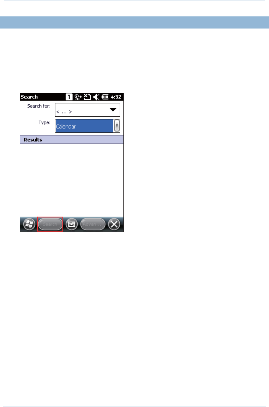
43
Chapt er 2 Learning Windows Embedded Handheld Basics
2.3. 5. FIND A FILE
1 . Tap Sta r t Scr een | Search Phon e.
2 . I n t he “Search for” box, enter the file nam e, keyword, or ot her inform at ion you
want t o search for. I f you have searched for this it em before, tap the drop- down
list and select it .
I n t he “Type” box, select a dat a t ype to help m inim ize your search. I f t he dat a
type of your file is other than list ed, you m ay try “ Larger than 64 KB” . However, if
the target file is less than 64 KB, it will not be searchable.
3 . Tap Sear ch.
4 . I n t he Result s list, tap t he it em you would like to open.

44
9200 Mobile Comput e
r
Ref erence Manual
2.4. USING ACTIVESYNC
Microsoft ’s syncing tools enables users to update or back up the dat a on t heir handheld
devices t o desktop com put ers.
Two syncing tools are feat ured by Microsoft - ActiveSync and Windows Mobile Device
Cent er ( WMDC). Which tool t o use depends on which OS is running on your PC:
O.S. Syncing Program
Windows Vista, Windows 7, Windows 8 WMDC
Windows XP SP3 or earlier ActiveSync
ActiveSync and WMDC are downloadable from Microsoft ’s website. Download and install
the right one on your PC. Before syncing your PC and device, m ake sure your PC has the
appropriate syncing t ool installed.
Hereaft er in t his m anual, we will focus on Act iveSync only. For WMDC usage, see its
docum ent ation or help file.
2.4. 1. SYNCHRONIZATION WITH YOUR COMPUTER
1 . Follow these instructions for initial Act iveSync operat ion:
Connect the m obile com puter and your PC with t he Snap- on Cable or Cradle.
Turn on the m obile com puter.
2 . Your com puter will aut om at ically detect the USB device.
3 . Select which partnership t o set up. I f you want t o synchronize dat a between the
m obile com puter and your personal com puter, select St andard Partnership;
ot herwise, select Guest Partnership
4 . Wait a few seconds for the m obile com puter to get connected ( and synchronized if
a St andard Part nership is select ed).
Note: For Act iveSync via Bluet ooth, refer t o Using Bluetoot h.
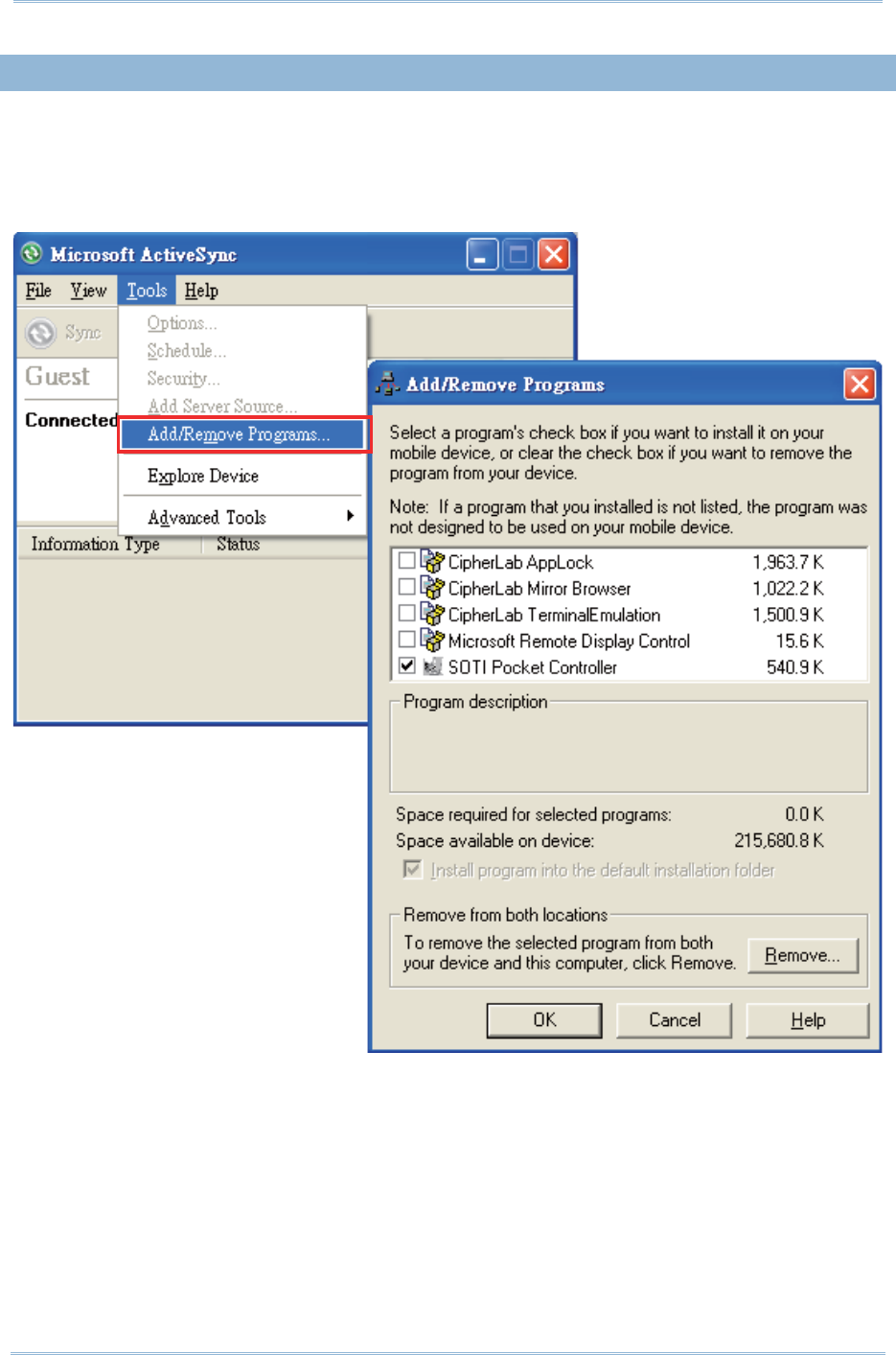
45
Chapt er 2 Learning Windows Embedded Handheld Basics
2.4. 2. ADD/ REMOVE PROGRAMS
On your PC, open Act iveSync and click Tools | Add/ Rem ove Progra m s t o inst all a
program that is designed to be used on a m obile device running Windows Em bedded
Handheld. I f a previously installed user program is no longer desired, you m ay also
rem ove it from the system .

46
9200 Mobile Comput e
r
Ref erence Manual
Aside from using t he Add/ Rem ove Progra m s m enu option t o m anage program s, you
can also inst all and rem ove program s by copying and pasting t he installation file (or
executable file) to the locat ion of interest .
Alternative for Installing New Programs (Copy & Paste)
Follow these st eps to inst all a new program m anually.
1 . Establish USB connect ion bet ween your m obile com puter and your PC.
2 . On your PC, open Act iveSync and click Ex plore on the t askbar.
3 . Navigat e t o t he target folder, e.g. the Program s folder (\ W indow s\ Star t Me nu\
Progr am s), depending on where you wish t o access the program .
4 . Navigat e through file folders on your com puter to find the new program
( .CAB, .EXE, et c.)
5 . Right - click t he program and select Copy from the pop- up m enu.
6 . Re-open t he target folder in step 3. Right - click anywhere blank and select Pa st e
from the pop- up m enu.
7 . On the m obile com puter, tap t he past ed file to st art inst allat ion or execute the
applicat ion.
Alternative for Removing Programs
Follow these st eps to uninst all a program m anually.
1 . Go to Star t Scre en | Se t t in gs | Syst e m and select Rem ove Pr ogram s.
2 . Tap the nam e of t he program that you want t o delet e.
3 . Tap Rem ove.
4 . Tap Yes to uninst all t he program .
Note: I f the program does not appear in the list of installed program s, you m ay use File
Explorer to locate it. Tap and hold the program to select Delete from the pop- up
m enu.
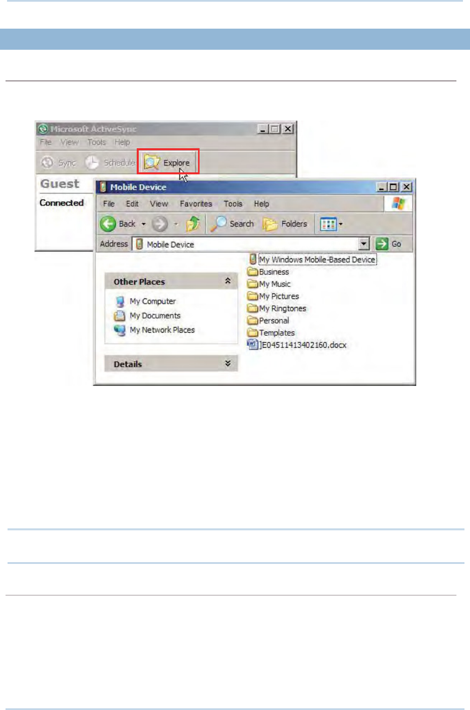
47
Chapt er 2 Learning Windows Embedded Handheld Basics
2.4. 3. EXPLORE DEVICE
Add a Program to Start Screen
1 . Establish USB connect ion bet ween your m obile com puter and your PC.
2 . On your PC, open Act iveSync and click Ex plore on the t askbar.
3 . Navigat e through file folders t o find t he program you desire.
4 . Right - click t he program and select Cre ate Short cut from the pop-up m enu.
5 . Right - click t he shortcut and select Cut from the pop- up m enu.
6 . Navigat e t o the Program s folder \ W indow s\ St a r t Me nu\ Progr am s.
7 . Right - click anywhere blank on the window and select Pa st e from t he pop- up
m enu. The new program will be added t o t he Program s folder.
8 . On the m obile com put er, go t o St a rt Scr een and t he new program will appear
now.
Note: Crea t e Shortcu t , Cut, and Pa st e : The sam e result can be perform ed by Copy
and Pa st e Short cut .
Create a New Folder
1 . Establish USB connect ion bet ween your m obile com puter and your PC.
2 . On your PC, open Act iveSync and click Ex plore on the t askbar.
3 . Navigat e t o the target folder where you wish t o create a new folder.
4 . Right - click anywhere blank on the window and select N e w Folder from the
pop-up m enu. A subfolder will be creat ed.

48
9200 Mobile Comput e
r
Ref erence Manual
2.5. SUSPEND & RESET
2.5. 1. SUSPENSION
The m obile com puter operat es cont inuously once it is powered on. To m inim ize power
consum pt ion, suspend t he m obile com puter if you are not actively using it . When t he
m obile com puter enters suspension, t he system is in a power- saving status and can be
quickly awoken to operat e as needed.
Enter Suspension
Press the Power key for about 0.2 seconds to enter suspension.
Resume from Suspension
Press the Power key for about 0.2 seconds to awake t he m obile com puter.
Alternatively, you m ay press the Scan key.
Warning: To save battery power, it is suggested t hat the m obile com puter is set to
be autom atically suspended when not in use. Refer to Pow er Managem ent
for m ore inform at ion about saving power.

49
Chapt er 2 Learning Windows Embedded Handheld Basics
2.5. 2. HARDWARE RESET (COLD BOOT)
When the m obile com puter runs slower than norm al or when it stops responding t o input ,
reset it wit h a hardware reset, also known as cold boot. This will rest art t he m obile
com puter and initialize RAM. All data cached in RAM w ill be gone aft er hardware reset ,
while flash m em ory and RTC will be ret ained.
Hardware Reset (= Cold Boot)
Met hod 1
1 . Press and hold down the power key for m ore than 3 seconds until a m enu
shows allowing select ion between rest art and power off.
2 . Tap Re st a r t . The m obile com puter will power off and t hen t urn on again to
show the Hom e Screen.
OR
Met hod 2
1 . Using the stylus, poke the reset butt on t o rest art t he device.
2 . The m obile com puter will power off and then t urn on again t o show t he Hom e
Screen.
Warning:
( 1) Data loss m ay occur if files are not properly saved before hardware reset .
( 2) Pressing t he power key and select ing Re st a rt (M ethod 1 ) is the recom m ended
m et hod for perform ing hardware reset. Perform Met h od 2 only when Me t hod 1 is
not effect ive.
( 3) Perform hardware reset only on the occasion when one or m ore applications on
the m obile com puter are m isbehaving, and t he system fails to respond.

50
9200 Mobile Comput e
r
Ref erence Manual
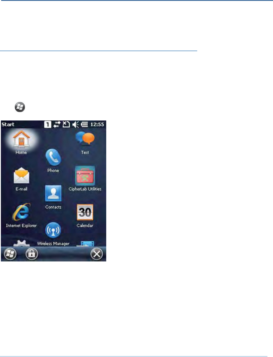
51
I n t his chapter, a brief on the syst em set t ings is provided for your reference.
IN THIS CHAPTER
3.1 CipherLab Smart Shell ................................................ 52
3.2ʳSet t ings .... ........ ........ ....... .. ...... ....... .......................... 56
3.3ʳDevice Name............................................................. 65
Tap t o open the St a rt Scr een, and t ap Se t t ings to configure relat ed set t ings.
Chapter 3
CONFIGURING 9200 MOBILE COMPUTER
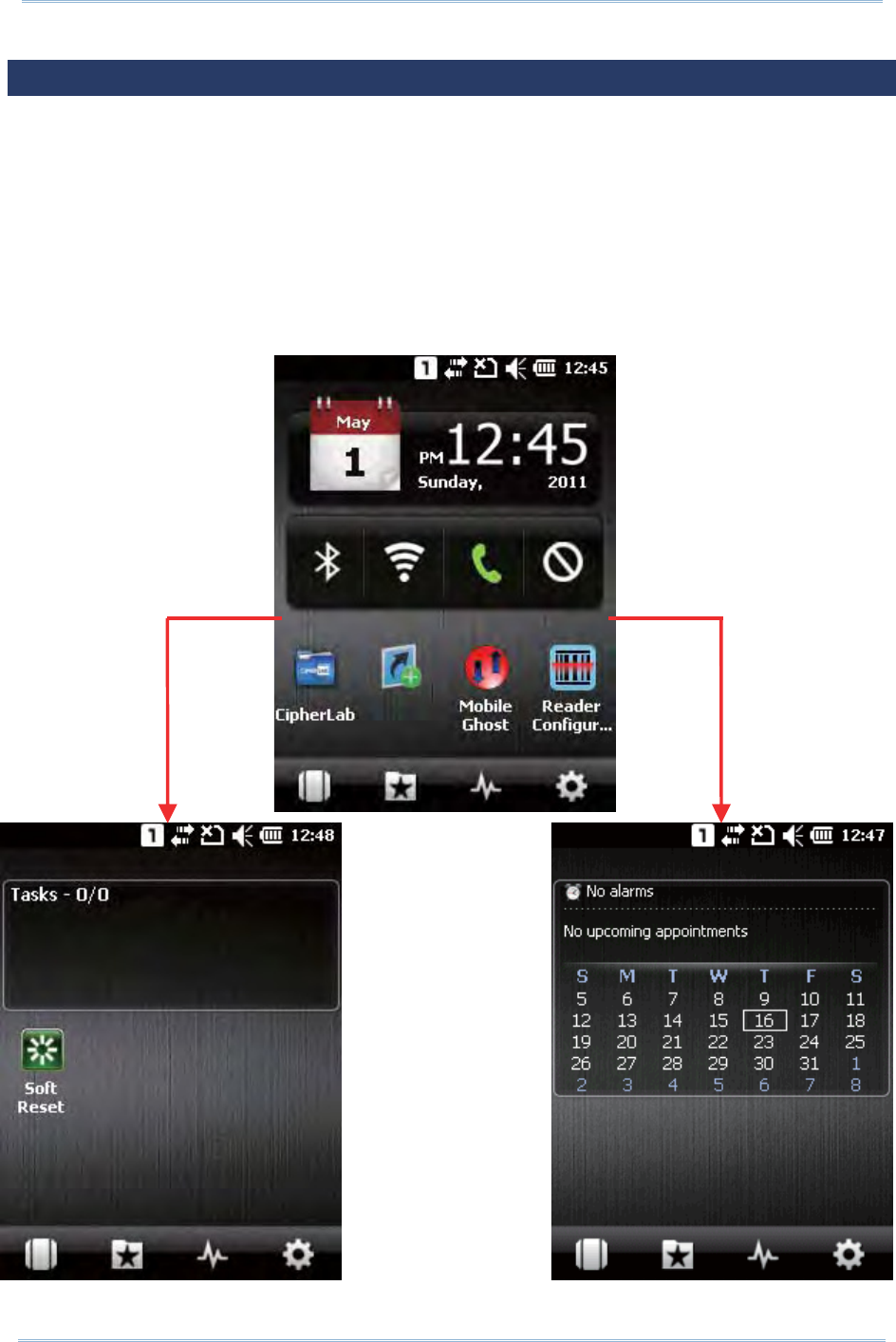
52
9200 Mobile Comput e
r
Ref erence Manual
3.1. CIPHERLAB SMART SHELL
CipherLab Sm art Shell is an opt ional OS interface that feat ures a Hom e Screen and a set
of screen views wit h program s and services arranged based on their properties. By
swit ching bet ween 3D carousel view or tiles view, you can easily access com m only used
program s and settings, or m anage your t asks, calendar, and contact s. You can also
adjust screen view s t o fit your preferences by cust om izing screen layout and item s
displayed.
When installed, t he m obile com puter will ent er CipherLab Sm art Shell when the system is
powered on.
Slide left to show
tasks
Slide left to show
calendar
Hom e Scr een

53
Chapt er 3 Configuring 9200 Mobile Comput e
r
Icon Description
Tap it for a 3D carousel view .
Provide a fast and convenient w ay t o access your favorite or r ecently used item s
and services.
Tap t o close any launched program s, or swit ch to a running program .
Support s set t ings and layout change based on t he view opened on- screen.
Tap it to switch Bluet oot h m ode ( invisible or discoverable) .
Tap it to enable/ disable Wi-Fi.
Tap it to enable/ disable GSM/ GPRS.
Flight Mode: Tap it to disable all wireless signals. The icon color will change from
white t o red.
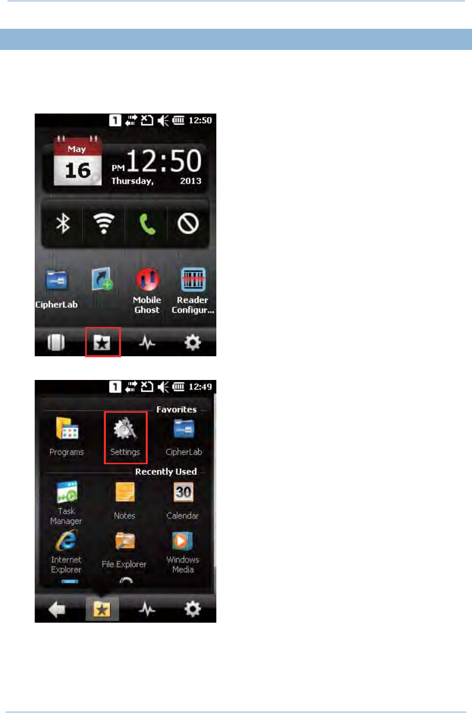
54
9200 Mobile Comput e
r
Ref erence Manual
3.1. 1. EXIT CIPHERLAB SMART SHELL
I f you would like t o exit Sm art Shell and return to t he built - in OS interface, follow t he
st eps below:
1 . Tap the “ Launcher” icon on the Sm art Shell hom epage.
2 . Tap the Se t t in gs icon to open the system set t ings page.
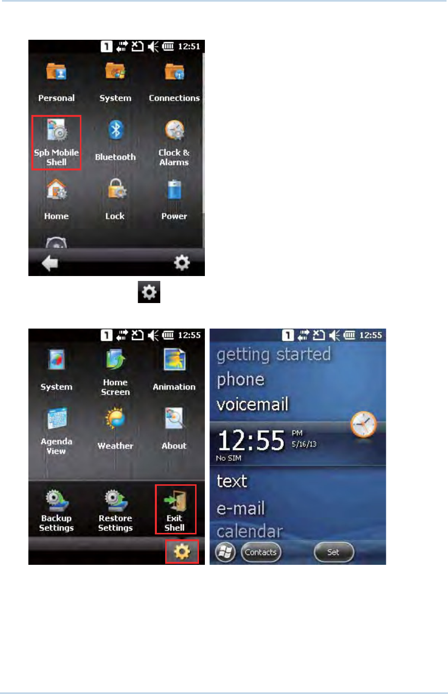
55
Chapt er 3 Configuring 9200 Mobile Comput e
r
3 . Tap the Sbp M obile She ll icon t o open Sm art Shell Set t ings.
4 . Tap the Settings icon seat ed on the lower right of the screen.
Tap Ex it Shell t o exit Sm art Shell and show the OS Hom e Screen.
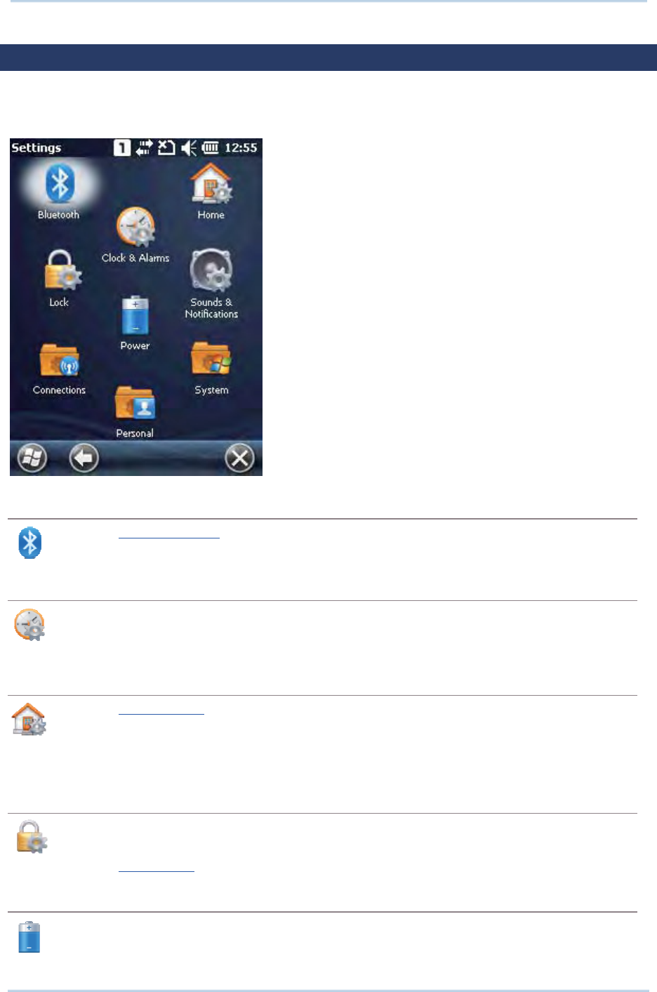
56
9200 Mobile Comput e
r
Ref erence Manual
3.2. SETTINGS
Tap Sta r t Scr een | Se t t in gs to access the settings m enu for configuring system t im e,
layout, sounds and not ifications, power, wireless connect ion, and m ore.
Bluetooth
Refer to Using Bluet oot h.
Clock & Alarms
Tim e t ab: Change t he dat e, t im e and tim e zone set tings. By default, the tim e zone
set tings will be aut om at ically synchronized and updat ed by not ification.
Alarm s tab: You m ay set up at m ost three alarm s to wake you up or as a rem inder.
Home
Refer to Hom e Screen.
Appearance t ab: Cust om ize the them e and background of the Hom e Screen.
I t em s tab: Select it em s t hat will appear on t he Hom e Screen, and configure Hom e
Screen t im eout .
Lock
Tap it to apply password prot ect ion to lim it access t o the m obile com puter, and any
screen or keypad input will be blocked.
Refer to Device Lock.
Power
Bat t er y t ab: You m ay view the current charge of m ain bat tery.
Advanced t ab: You m ay configure to t urn off the device w hen it is idle for a specific

57
Chapt er 3 Configuring 9200 Mobile Comput e
r
period of time, eit her on bat tery or ext ernal power.
Sounds & Notifications
Refer to Note: For Scanner decode and Scanner beam LED t o funct ion, LED notificat ion
m ust be enabled in Reader Configuration. See 198HEnable LED Notificat ion.
Audio.
Sounds tab: Configure sounds for specific actions, event s, program s, etc.
Notificat ions tab: Select t o play sounds as notificat ions for som e events.
Connections
Refer to Connect ions.
Personal
Refer to Personal.
System
Refer to Syst em .
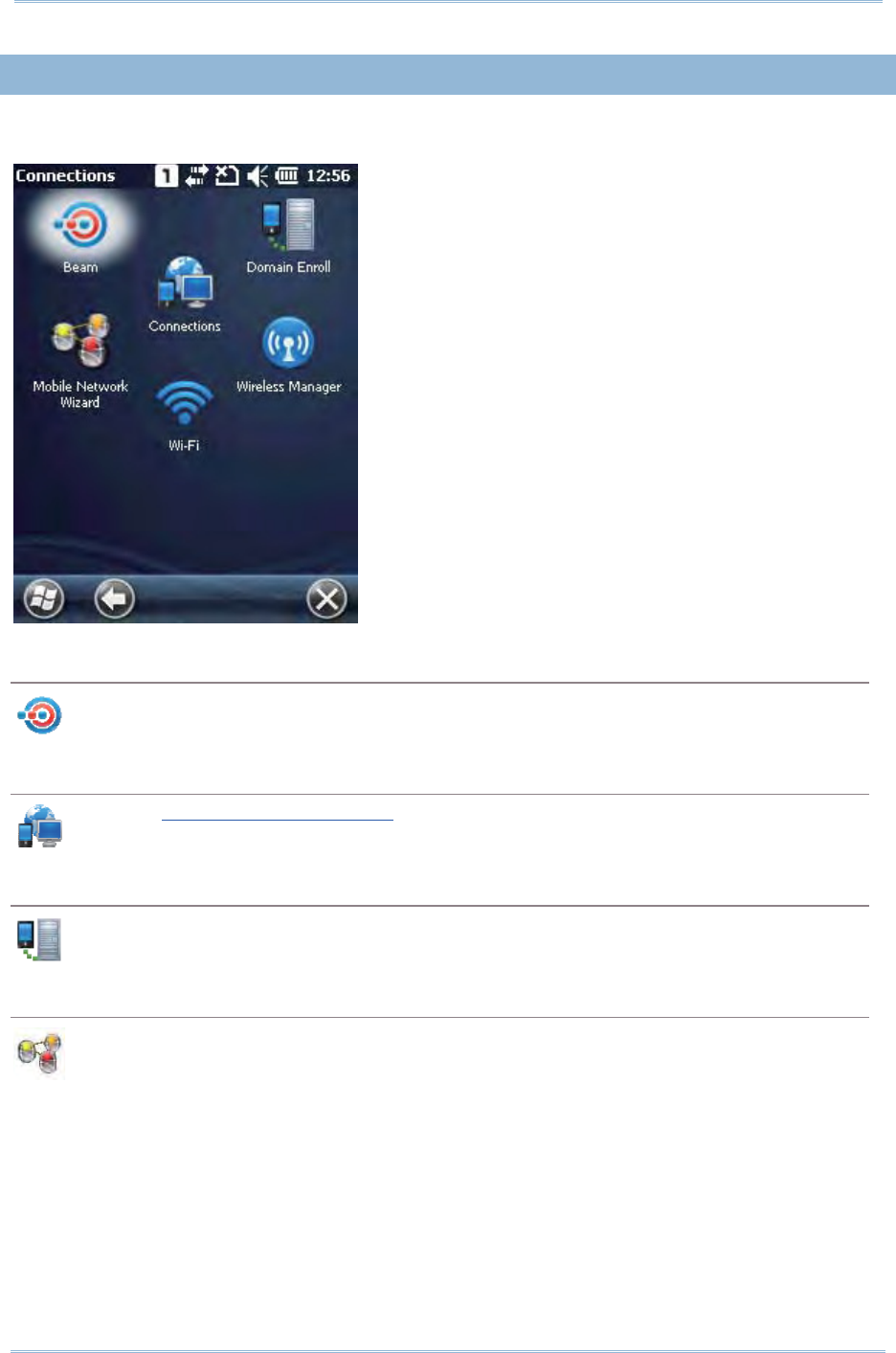
58
9200 Mobile Comput e
r
Ref erence Manual
3.2. 1. CONNECTIONS
Go to Star t Scre en | Se t t in gs | Connect ions.
Beam
Tap it to receive incom ing Bluetooth beam s.
Connections
Refer to Configuring GPRS Net work.
Domain Enroll
Connect s t o an SCMDM server wit h an enr ollm ent I D and password, allowing com pany
deploym ent on m ultiple m obile com puters.
Mobile Network Wizard
Select t o aut om at ically configure your network provider and APN when a SI M car d is
insert ed.
Actual set t ings depend on the net work provider. GPRS set tings can also be m anually
configured under Se t t in gs | Conne ct ion s | Conne ct ion s.
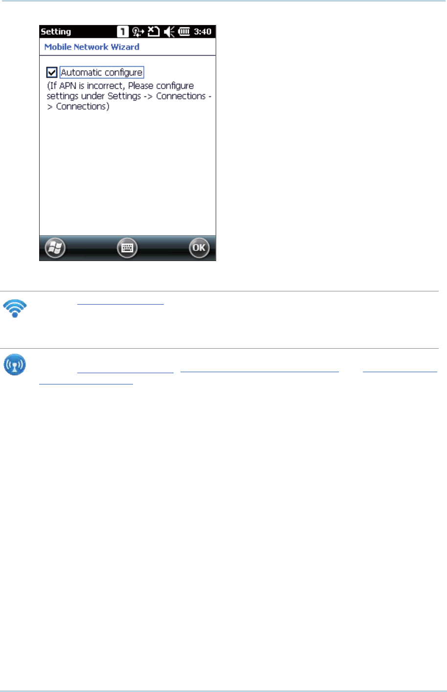
59
Chapt er 3 Configuring 9200 Mobile Comput e
r
Wi-Fi
Refer to Using 802.11 Radio.
Wireless Manager
Tap it t o enable/ disable t he Wi- Fi, Bluetooth or Phone Power . For related inform ation,
refer t o
ᙑᎄ
!
ބլࠩᅃࠐᄭΖ
, Power On BT via Wireless Manager and Power On Phone
via Wireless Manager.
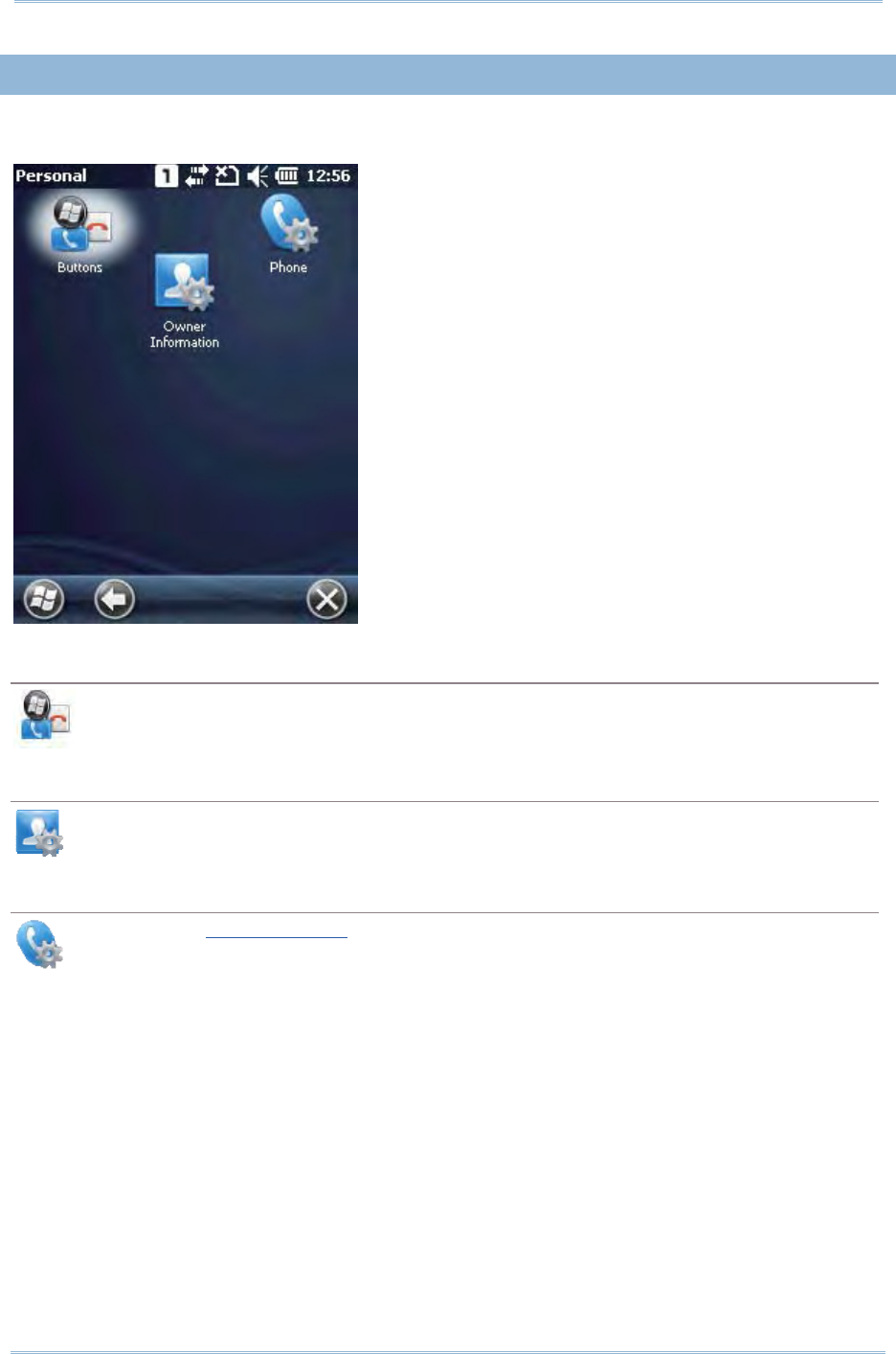
60
9200 Mobile Comput e
r
Ref erence Manual
3.2. 2. PERSONAL
Go to Star t Scre en | Se t t in gs | Pe r sona l.
Buttons
Tap it to adjust the character input repeat delay and rat e, m ove t he slider to right or
left for repeat speed.
Owner Information
I dent ification tab: Ent er your cont act inform ation.
Notes t ab: Ent er your not es.
Phone
Refer to Using the Phone.
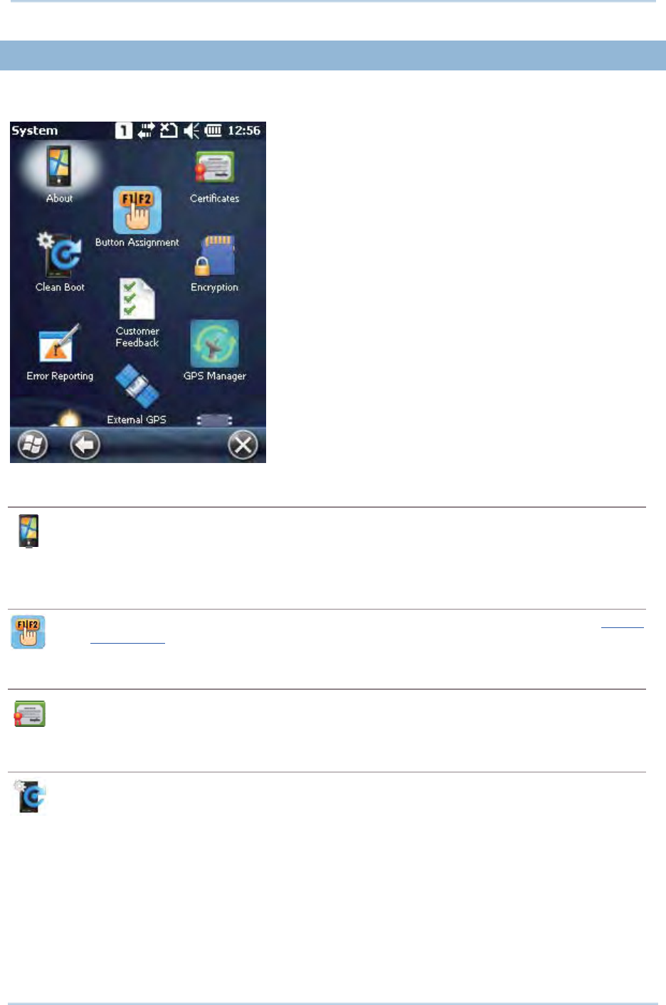
61
Chapt er 3 Configuring 9200 Mobile Comput e
r
3.2. 3. SYSTEM
Go to Star t Scre en | Se t t in gs | Syst e m .
About
Version tab: Displays inform at ion of OS soft ware, processor, et c.
Device I D tab: Ent er a nam e and descript ion for ident ifying t he m obile com put er .
Copyrights t ab: Displays im portant statem ents on copyright s.
Button Assignment
Redefines key functions under keypad’s norm al and funct ion m ode. See Butt on
Assignm ent for m ore details.
Certificates
View or m odify digital certificat es that som e applications use to est ablish trust for secure
connect ions.
Clean Boot
Allows clean boot of t he m obile com put er , which elim inat es all user dat a and rest ores t he
m obile com puter back to fact ory set tings.
A confirm at ion key is required for clean boot .
A warning m essage will show asking for confirm ation before t he m obile com puter
re- boots and st arts the clean boot process.
Make sure you have com plet ed data backup to an ex ternal st orage before perfor m ing
clean boot.
I t is recomm ended t o have t he m obile com put er connected to an external power
source when perform ing clean boot.
62
9200 Mobile Comput e
r
Ref erence Manual
Customer Feedback
Sends cust om er feedback t o Microsoft for im proving Windows Em bedded Handheld
soft ware.
Encryption
Encrypt s files stored on t he SD card. The encrypt ed files can only be read on t he m obile
com puter.
Error Reporting
Det er m ines whether to enable error report ing t o help Microsoft im prove Windows
Em bedded Handheld software. By default , it will autom atically collect errors and report to
Microsoft.
External GPS
Program s tab: Specify a program port for m ult iple GPS-enabled program s to access
GPS dat a.
Hardware t ab: For t he GPS program port t o work, you m ust specify the correct
hardware port . For exam ple, if you are using the GPS receiver int egrat ed on the
m obile com puter, select COM 7 and 4800 for baud r ate.
Access tab: By default , Windows Em bedded Handheld m anages access t o your GPS
receiver and allows m ultiple program s t o obt ain GPS data sim ultaneously. I f you
clear t he check box, som e program s m ay not be able t o obtain GPS dat a.
GPS Manager
AGPS t ab: Select t o enable AGPS funct ion to im prove GPS perfor m ance.
Ephem eris t ab: Configure how t o download ephem eris dat a, or tap Dow nload to
update ephem eris at any t im e. The data is valid for seven days according t o the
system dat e and tim e. The dat e of last download will be displayed at t he lower left of
the screen.
Keypad Backlight
Change keypad backlight behavior. By default, the keypad backlight will be aut om at ically
turned off for five seconds when any key is pressed.
Managed Programs
Manages program s that are installed in RAM.
Memory
Main tab: View t he current capacity and usage of the onboard RAM, which is divided
into file st orage and program usage.
St orage Card t ab: View m em ory usage of t he Flash Disk folder or st orage card.
Reader Configuration
CipherLab’s scanning ut ility which allow s configurat ion of sym bology, scan set tings,
and output and notificat ion set tings.
63
Chapt er 3 Configuring 9200 Mobile Comput e
r
Regional Settings
Region tab: Cust om ize the appearance and form at ting t o your geographic region.
Num ber tab: Cust om ize the num ber form at.
Currency t ab: Cust om ize the currency form at.
Tim e tab: Custom ize t he tim e form at.
Dat e t ab: Custom ize t he date form at .
Remove Programs
Rem oves program s that are st ored in RAM.
Screen
Alignm ent t ab: Align the screen for calibrat ion.
ClearType t ab: Apply Clear Type font s.
Text Size t ab: Use the slider to adjust the text size.
Screen Backlight
Bat t er y Power t ab: Configure when t o turn on/ off the backlight and brightness of the
LCD backlight when on batt ery power.
Ext ernal Power t ab: Configure when to t urn on/ off t he backlight and bright ness of
the LCD backlight when on external power.
System Information
Displays im portant device inform ation for softw ar e package, hardware m odules, and
m anufacture info.
Task Manager
Lists all applicat ions which are currently running on t he m obile com put er . Tap and hold
an applicat ion t o swit ch to it or end it if processing too m any applications takes up a lot
of m em ory or CPU resource.
Time Synchronization
Synchronizes t he m obile com puter’s system t im e via two m et hods, SN TP and GPS.
SNTP tab: Manually synchronizes the m obile com puter’s t im e w ith an NTP server.
Synchronized t im e will be w rit ten to RTC and syst em tim e will be updated.
GPS tab: Get s t im e inform ation t hrough GPS data packet.
USB Connection
Set s USB connect ion bet ween Act iveSync and Mass Storage when t he m obile com put er is
connect ed t o a Windows-based PC.
Act iveSy nc: Synchronizes t he m obile com puter and PC t hrough ActiveSync
connect ion. This is t he default set ting.
Ma ss St ora ge: Pr esents the m obile com puter wit h an SD car d inst alled as a storage
device. I f no SD card is inst alled, t he directory on the PC w ill be blank.

64
9200 Mobile Comput e
r
Ref erence Manual
USB to PC
Disable this t o swit ch USB connect ion from RNDI S to PPP. When the m obile com puter is
connect ed t o your PC t hrough USB connection, internet sharing t o t he m obile device will
be enabled and ActiveSync connect ion m ight be interrupted. Disable advanced net work
funct ionality to t roubleshoot Act iveSync connect ion problem s.
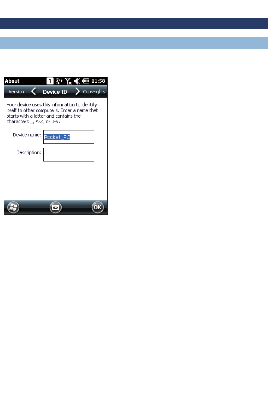
65
Chapt er 3 Configuring 9200 Mobile Comput e
r
3.3. DEVICE NAME
3.3. 1. CHANGE DEVICE NAME
Go to St art Screen | Set t ings | Syst em , and tap About t o change t he device nam e on
the Device I D t ab to m ake the device m ore recognizable.

66
9200 Mobile Comput e
r
Ref erence Manual
3.4. UPDATE OS IMAGE
Upgrading t he OS im age helps optim ize t he m obile com puter’s perform ance and
funct ionalit y. The upgrading process relies on a m em ory card, and an .nb0 OS im age file.
1 . On your PC, copy the latest OS im age file t o t he m icroSD card.
2 . I nsert t he m icroSD card into t he card slot as described in Using Mem ory Card.
3 . Power on t he m obile com puter by pressing t he power but ton, and at t he sam e
tim e press t he Volum e Down key on t he right side of the m obile com puter
4 . The m obile com puter powers on and direct ly ent ers firm ware upgrade m ode.
Syst em upgrade with t he OS im age file will st art aut om at ically. An upgrade
progress bar will show on-screen.
St arting upgrade OS upgrading
Upgrade start!!
Status :
Checking all files…
Start to upgrade firmware!
50%
Upgrade start!!
Status :
Upgrading Firmware
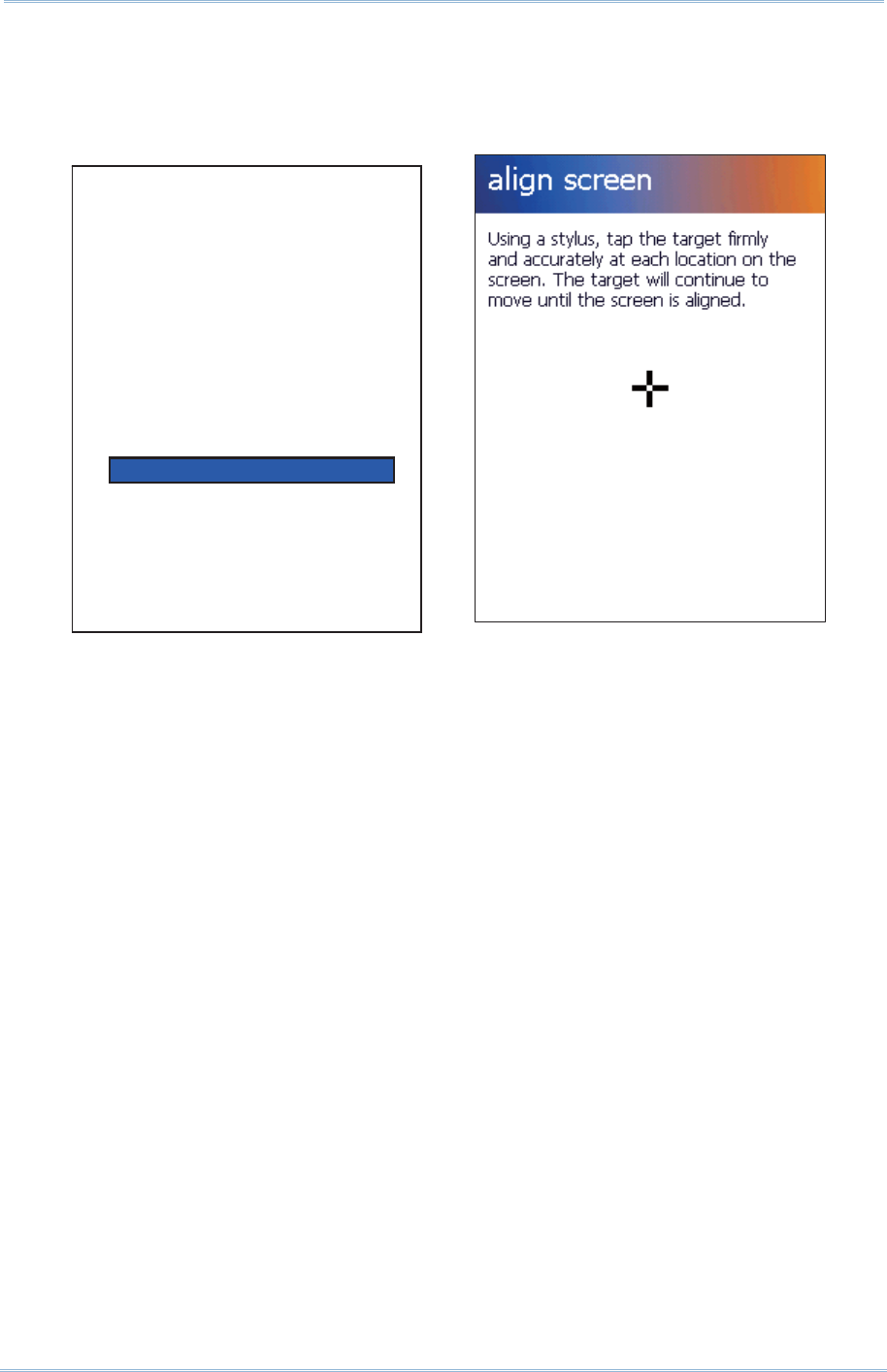
67
Chapt er 3 Configuring 9200 Mobile Comput e
r
5 . When OS upgrade is com plet e, the m obile com puter will restart . After system
st artup, t ap the screen t o ent er calibration.
OS upgrade com plet e Restart and enter Calibrat ion
Start to upgrade firmware!
100%
Status :
Firmware updated complete.

68
9200 Mobile Comput e
r
Ref erence Manual

69
The Wi- Fi m odule integrated on t he m obile com puter let s you configure and connect to
network wirelessly.
IN THIS CHAPTER
4.1ʳWi-Fi Power............................................................... 70
Chapter 4
USING 802. 11 RADIO

70
9200 Mobile Comput e
r
Ref erence Manual
4.1. WI-FI POWER
The m obile com puter is capable of Wi-Fi, a wireless netw orking technology m aking use of
an access point , also known as “ hot spot” , to connect to a wireless local area network.
To use Wi-Fi, the m obile com puter has to connect to a hotspot. Som e hot spot s are open
for connect ion while others request a key to authent icat e access. I f this is the case, the
authentication key m ust be included in the m obile com puter’s Wi- Fi set tings.
Wi- Fi set t ings and power are cont rolled via Sum m it Client Ut ilit y ( SCU) . Windows Zero
Configuration (Wireless Manager) can only be used to view Wi- Fi power and connect ion
st at us.
Turn off Wi- Fi when it isn’t used to ext end bat t ery life. SeeʳTurn On/ Off Wi-Fi Power.
Sum m it Client Ut ilit y functions by t he use of Wi- Fi profiles. Profiles are a set of radio and
security set t ings t hat are stored in the regist ry. You m ay creat e, renam e, edit and delet e
profiles, as well as alter global settings t hat apply to every profile or t o Sum m it Client
Ut ilit y ( SCU) it self. For m ore det ails on profile settings, please visit the following websit es:
http: / / w ww.sum m it dat a.com / docum ent ation.ht m l
http: / / www.sum m it dat a.com / Docum ent s/ sum m it_users_guide_3_03.htm l
http: / / www.sum m it dat a.com / Docum ent s/ sum m it_quick_start _v3_03.htm l
4.1. 1. LAUNCH SCU
Wi- Fi set t ings can be adj usted wit h Sum m it Client Ut ilit y. Within this application are three
tabbed pages which allow users t o select the access point for connection, creat e profiles
for better m anagem ent, perform diagnost ics on connectivit y, and fine- tune property
set t ings to m eet their individual requirem ents.
To launch SCU:
1 . On St art screen, tap Se t t in gs | Syst e m | SCU .
SCU opens showing three tabbed pages: St a t us, Conf igu ra t ion , and
D ia gn ost ics.
The following sect ions explicate in det ail t he set t ings on each of t hese pages.
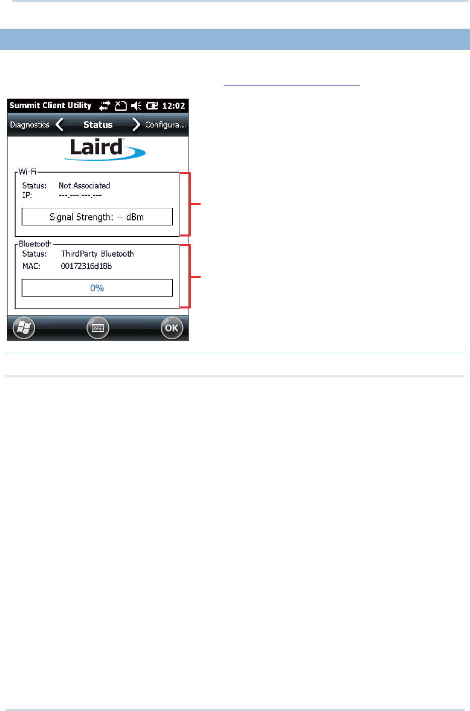
71
Chapt er 4 Using 802. 11 Radio
4.1. 2. STATUS TABBED PAGE
The St at us t abbed page provides basic inform at ion on WLAN connection and Bluetoot h
st at us. Wi- Fi set t ings can be configured in Configuration Tabbed Page.
Note: SCU does not currently support viewing or configuring Bluet ooth set t ings.
Wi- Fi status
Bluet oot h status (service not available now)
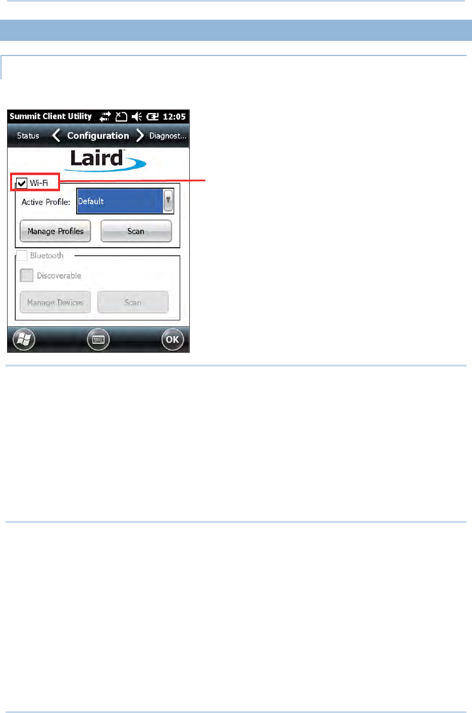
72
9200 Mobile Comput e
r
Ref erence Manual
4.1. 3. CONFIGURATION TABBED PAGE
TURN ON/OFF WI-FI POWER
Select the Wi- Fi checkbox t o t urn on Wi-Fi power. Deselect it t o shut down Wi-Fi.
Note:
( 1) Wi- Fi connection st atus will be reflect ed under W ire less M a nager , which can be
accessed by tapping the Title bar | W ireless Mana ger icon, or Sta r t Scr een |
Se t t in gs | Con ne ct ion s | W ire less M ana ge r. When Wi- Fi power is off, the
st at us will display as “ No signal” . When Wi- Fi power is on but no active connection
is est ablished, the status will display as “ Available” . When a WLAN connection is
est ablished, the st at us will display as “ Net work Card” . Wireless Manager cannot be
used to control Wi-Fi power.
( 2) SCU does not allow configurat ion of Bluetoot h sett ings. To est ablish and m anage
Bluetooth connections, t ap St art Scree n | Set t ing s | Blue t oot h.
Turn on Wi- Fi power
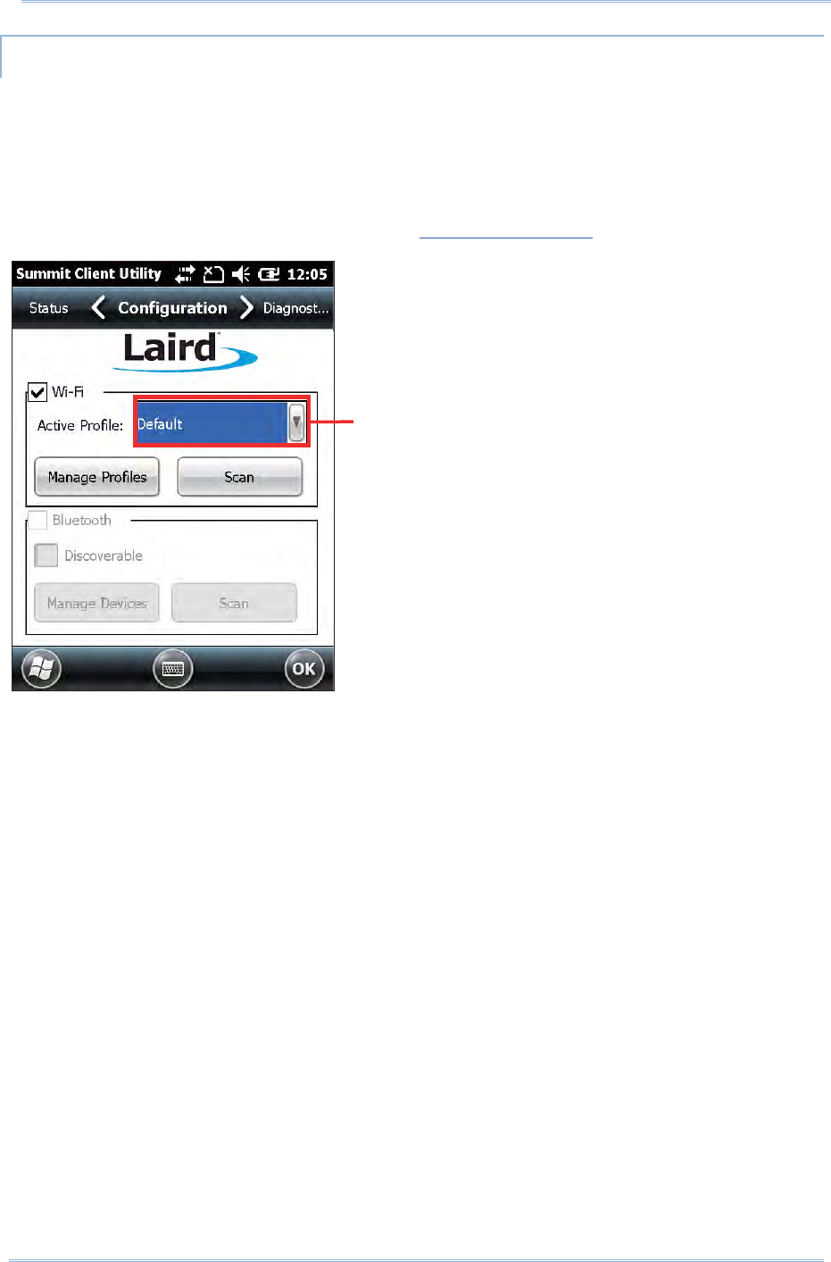
73
Chapt er 4 Using 802. 11 Radio
ACTIVE PROFILE
A profile is a set of param eters that define t he m anner which a device associates to a
wireless LAN (WLAN) infrastructure. A profile cont ains inform ation including the System
Set I dentifier (SSI D, t he "nam e" of the WLAN infrast ructure) , m eans of data encrypt ion,
authentication type, and security credentials.
Select an active profile in the drop-down box on the Configur ation t abbed page. To add
a profile other than the “ Default” profile, see Creat e Wi-Fi Profile.
Tap t o select an act ive profile
in the drop-down bar
74
9200 Mobile Comput e
r
Ref erence Manual
CREATE WI-FI PROFILE
To creat e a Wi- Fi Profile:
1 . Open SCU as described in Launch SCU.
2 . Tap the Configurat ion tab to show t he Configuration tabbed page.
3 . Tap Scan to view a list of access point s that are broadcasting their SSI Ds. You
m ay sort the list by tapping t he colum n headers.
Tap Re fresh to updat e the list of available access points.
Item Description
SSI D Service Set I dent ifier ( SSI D)
RSSI Received Signal St rengt h I ndication ( RSSI )
Secure I ndicat es whether data encrypt ion is enabled: t rue or false
4 . Tap twice on any of the access point s t o creat e a new profile for it. A prom pt
shows confirm ing whet her t o creat e a profile with t he identified SSI D, encrypt ion
and EAP type. Tap Ye s to continue.
75
Chapt er 4 Using 802. 11 Radio
5 . A profile set t ings page opens showing detailed radio settings. Tap each item and
adjust it s Value t o suit your needs.
6 . When finished fine-tuning all set tings, t ap Com m it t o save the profile.
7 . Tap OK on the softkey bar t o close Profile Set t ings page and return to
Configuration set tings.
I f you would like t o direct ly act ivate the newly created profile, select it as t he
Active Profile on the Configurat ion settings page.
76
9200 Mobile Comput e
r
Ref erence Manual
MANAGE WI-FI PROFILE
To m anage your profiles:
1 . Open SCU’s Configu ra t ion tabbed page as described in Create Wi- Fi Profile.
2 . Tap Manage Profiles t o open the Profile set t ings page.
Item Description
Profile When SCU is first launched, “ Default”
is the act ive profile. Unless it is
m odified, this profile does not specify
an SSI D, EAP t ype or encryption
m et hod. You can chose to do the
following:
Modify t he default profile
Tap N e w to add a new profile
Select an exist ing profile from t he
drop-down m enu and configure
77
Chapt er 4 Using 802. 11 Radio
New Tap N e w and ent er a unique nam e for t he profile. Configure t he Radio
set t ings, Encryption, EAP Type, and other set t ings for t his new profile.
The nam e for each profile m ust be unique
You can define up t o 20 profiles
Delet e Select a profile from t he drop- down m enu and t ap Delet e.
You cannot delet e the Act ive Profile. Make sure the select ed profile is not
the act ive profile under Configuration tabbed page.
Radio
Set t ings
Aft er selecting a profile in t he Profile drop-down bar, configure radio set tings
in t he scrollable m enu below.
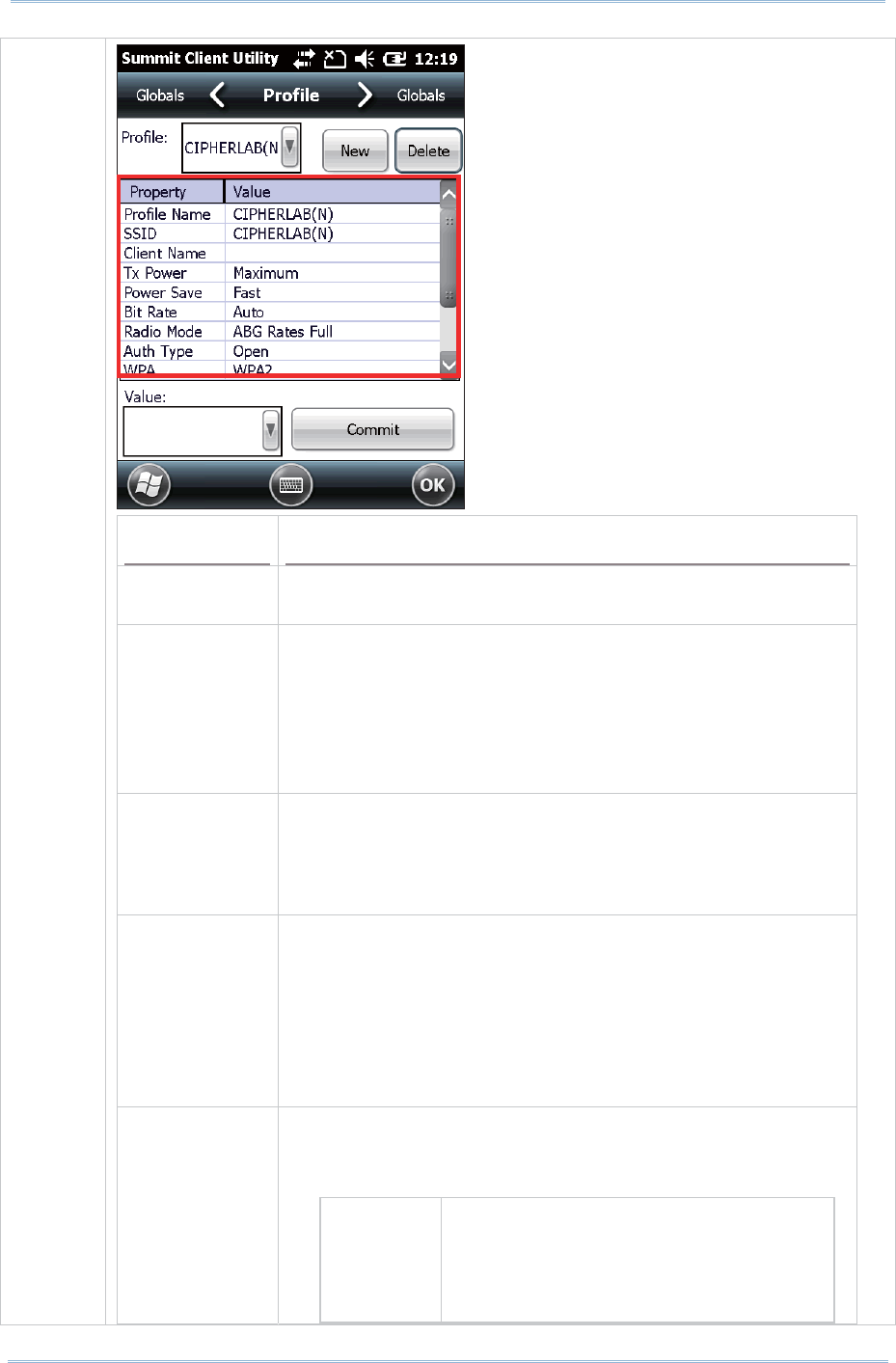
78
9200 Mobile Comput e
r
Ref erence Manual
Property Description
Profile Nam e Tap t o renam e t he select ed profile. Up to 32 characters
allowed.
SSI D Service Set I dent ifier ( SSI D) for t he WLAN infrast ructure
to which the radio will connect . I f no SSI D is specified,
the radio will only associat e t o an access point that
broadcast s its SSI D.
Value: A st ring of up t o 32 charact ers
Default : None
Client Nam e Nam e assigned to the m obile com puter wit h Sum m it
radio inst alled.
Value: A st ring of up t o 16 charact ers
Default : None
Tx Power The power of t he radio in m illiwat s ( m W) . I n cert ain
cases this value will be overwrit t en by the access point,
which will dictate t o t he radio which power t o use.
Value: Maxim um ( Maxim um power defined for t he
current regulat ory dom ain) or a specified percentage
75% , 50% , 25% , 10%
Default : Maxim um
Power Save Power save m ode for the radio. Set the radio to its
optim um power-consum ption setting.
Value:
CAM Const ant ly Awake Mode ( CAM) keeps
the radio powered up cont inuously so
there is m inim al lag in m essage
response t im e. This m ode consum es
the m ost power but offers t he highest

79
Chapt er 4 Using 802. 11 Radio
throughput . I t is recom m ended when
AC power is in use.
Maxim um I n Max Power Savings (Max PSP)
m ode, t he access point buffers
incom ing m essages for the radio,
which wakes up periodically and
connect s t o t he access point t o see if
any buffered m essages are waiting.
The radio request s buffered m essages
and then goes back to sleep. I t
conserves t he m ost power but offers
the lowest throughput. I t is
recom m ended when bat t ery power is
in use.
Fast Power Save Mode (Fast PSP) switches
between the t wo m odes described
above, depending on net work t raffic.
This m ode switches to CAM when
ret rieving a large num ber of packet s
and switches back t o PSP (= Power
Save Polling) after the packet s have
been retrieved. I t is recom m ended
when power consum ption is a concern
but you need great er t hroughput than
that allowed by Max PSP.
Default : Fast
Bit Rate The m easurem ent of how m uch dat a is transm it t ed in a
given am ount of tim e from one locat ion t o another.
Value: Aut o ( rate is negot iat ed autom atically with the
AP)
Default : Auto
Radio Mode Use of 802.11a/ b/ g/ n frequncies and data rat es when
int eract ing wit h an AP, or the use of ad hoc to associat e
to a st ation radio.
Value: B rat es only, BG rat es full, G rates only, BG
LRS, A rates only, ABG rat es full, BGA rates full, Ad
Hoc
B rates
only
1, 2, 5.5, and 11 Mbps.
BG rates
full
All B and G rat es, plus N rat es if
support ed.
G rat es
only
6, 9, 12, 18, 24, 36, 48, and 54
Mbps.
BG LRS 1, 2, 5.5, 6, 11, 24, 36, and 54 Mbps.
This should only be used wit h Cisco
APs running I OS in aut onom ous m ode
( wit hout controllers) .

80
9200 Mobile Comput e
r
Ref erence Manual
A rates
only
6, 9, 12, 18, 24, 36, 48, and 54
Mbps, plus N rat es if supported.
ABG rat es
full
All A rates and all B and G rates, wit h
A rates (the 802.11a radio) preferred,
plus N if supported.
BGA rat es
full
All B and G rat es and all A rat es, with
B and G rat es ( t he .11g radio)
preferred, plus N rat es if support ed.
Ad Hoc When select ed, the Sum m it radio
associates to anot her stat ion radio
that is in ad hoc mode and has the
sam e SSI D and, if configured, st at ic
WEP key.
Default : ABG rates full
Aut h Type 802.11 authenticat ion type used when associating to an
AP.
Value: Open, Shared ( shared- key), LEAP
( Network- EAP)
Default : Open
I t is recom m ended that the default setting Open is
select ed.
WPA WPA and WPA2 support the sam e authenticat ion
m et hods and sim ilar key m anagem ent m ethods; the
difference is m ainly in area of encryption. WPA defines
TKI P as t he prim ary encryption m et hod, while WPA2
defines AES- CCMP as t he prim ary encryption m et hod.
Value: None, WPA, WPA2
Default : None
Encrypt ion This specifies t he t ype of key used to encrypt and
decrypt t ransm itt ed data, and how t hat key is specified
or derived. Select Encryption type in the Value
drop-down box.
Item Description
None N/ A
TKI P The encryption m et hod defined with
WPA. TKI P uses RC4 encrypt ion as does
WEP.
AES-CCMP The encrypt ion m et hod defined with I EEE
802.11i and certified wit h WPA2.
AES-CCMP is stronger t han RC4
WEP The encryption m et hod defined wit h the
original I EEE 802.11 standards; encrypts
transm itt ed data using 64-bit or 128-bit
encryption.

81
Chapt er 4 Using 802. 11 Radio
Encryption CKI P CKI P is supported for use only wit h static
WEP. For CKI P, encrypt ion keys need to
be defined in SCU; for CKI P- EAP,
encryption keys are derived dynam ically
from an EAP authentication.
Aut hentication This is the protocol used to authent icat e t he device and
it s user if t he WLAN uses the Enterprise version of Wi- Fi
Protect ed Access ( WPA) and WPA2. Select Authenticat ion
type in the Value drop-down box, then ent er the
credent ials necessary for each type in the appeared
fields.
Item Description
None N/ A
LEAP Credent ials values for LEAP:
User Nam e ( up to 64 charact ers)
Password ( up to 32 charact ers)
EAP- FAST Credent ials values for EAP- FAST
User Nam e ( up to 64 charact ers)
Password ( up to 32 charact ers)
PAC Filenam e ( up t o 32
characters) : You m ay create a
prot ected access credent ial (PAC)
for each client device. When
creat ing a PAC m anually, you
m ust store it in the direct ory
identified in Certs Path on t he
Globa ls set t ings page. To use
autom at ic provisioning, leave this
field blank.
PAC Password ( up to 32
characters)
PEAP- MSCHAP
PEAP- GTC
Credent ials values for PEAP- MSCHAP,
PEAP- GTC, EAP- TTLS:
User Nam e ( up to 64 charact ers)
Password ( up to 32 charact ers)
CA Cert : Filenam e and extension
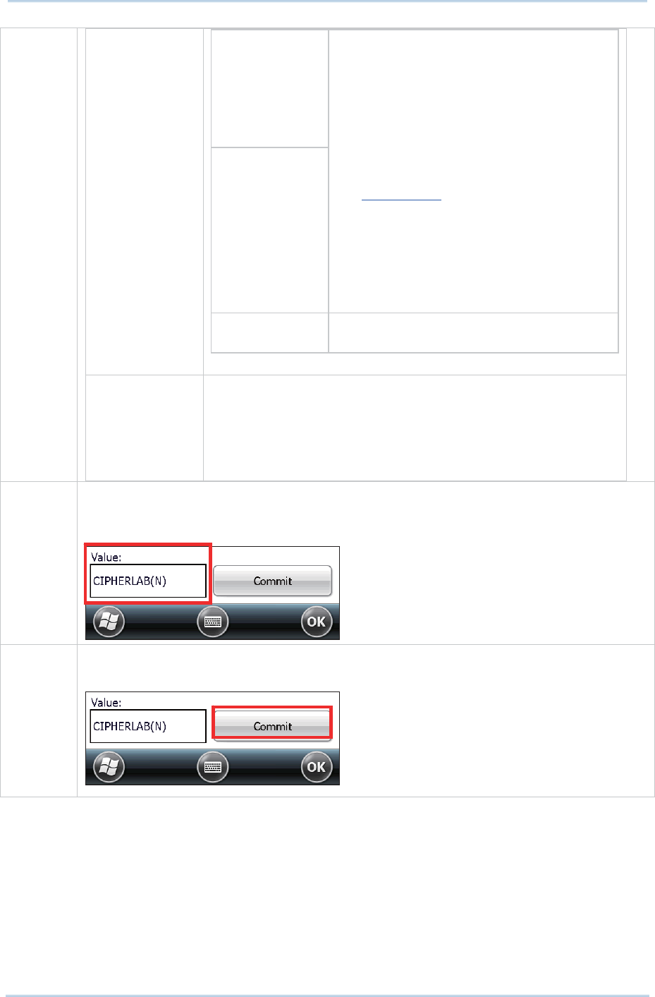
82
9200 Mobile Comput e
r
Ref erence Manual
EAP- TLS
PEAP- TLS
Credent ials values for EAP- TLS and
PEAP- TLS:
User: Usernam e or
Dom ain/ Usernam e (up t o 64
characters)
User Cert: Filenam e and ext ension
of user cert ificat e residing in the
Microsoft certificate st ore. See
Certificates.
CA Cert : Filenam e and extension
of root certificate authorit y ( CA)
digital cert ificat e ( up to 32
characters) . Specify t he Certs Pat h
in Globals sett ings page > Ce rt s
Pat h .
PSK Pre-shared keys ( PSK) consist of up t o
256 bits entered as a string of up t o
Fast Reaut h The expedit ed WPA key handshake used t o reduce
roam ing tim e to 125 m sec or less. Available for WPA
TKI P and WPA2 AES- CCMP.
Value: None, CCKM
Default : None
Value Use t his box to change the value of a selected item . Depending on the item
propert y, t his can be done by choosing a value from a drop- down list , or
entering the desired value with t he on-screen or physical keypad.
Com m it After m aking any changes on t he Profile t abbed page, t he Com m it but t on
m ust be t apped in order for the settings to take effect .
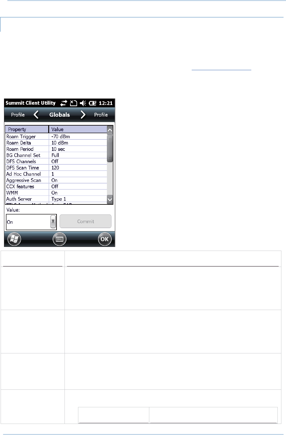
83
Chapt er 4 Using 802. 11 Radio
MANAGE GLOBAL SETTINGS
Global set tings include radio and security settings that apply to all profiles in SCU.
To open the Global settings page:
1 . Open SCU’s Configurat ion t abbed page as described in Creat e Wi- Fi Profile.
2 . Tap Manage Profiles t o open the Profile set t ings page.
3 . Tap the Globals tab t o open the Global set t ings page.
Property Value
Roam Trigger When t he m oving average RSSI from the current AP is w eaker t han Roam
Trigger, radio does a roam scan where it probes for an AP with a signal
that is at least Roam Delt a dBm stronger.
Value ( dBm ): - 50, - 55, - 60, - 65, -70, -75, - 80, - 85, - 90, Custom
Default: - 70 dBm
Roam Delt a When Roam Trigger is m et , a second AP’s signal st rength (RSSI ) m ust be
Roam Delta dBm st ronger t han t he m oving average RSSI for the current
AP before radio will at tem pt to roam to the second AP.
Value ( dBm ) : 5, 10, 15, 20, 25, 30, 35
Default: 10 dBm
Roam Period After associat ion or roam scan ( wit h no r oam ) , radio will collect RSSI scan
data from Roam Period seconds before considering roam ing.
Value ( sec): 5, 10, 15, 20, 25, 30, 35, 40, 45, 50, 55, 60, Cust om
Default: 10 (seconds)
BG Channel Set Defines t he 2.4 GHz channels to be scanned when the radio is
cont em plating a roam and needs to det erm ine what APs ar e available.
Item Description

84
9200 Mobile Comput e
r
Ref erence Manual
Full All channels
1, 6, 11 The m ost com m only used 2.4 GHz channels
1, 7, 13 For ETSI and TELEC radios only
Custom I ndicat es the system registry has been
edited t o include a value other than those
available in t he drop- down value
Default: Full
DFS Channels I ndicat es whether to support 5 GHz ( 802.11a) channels where dynam ic
frequency select ion (DFS) is required.
Value: On, Off
Default: Off
DFS Scan Tim e Enables det erm ining t he dwell ( listen) t im e when passively scanning on a
DFS channel.
Valid range of 20- 500 m s configurable
Default: 120
When t he DFS Scan Tim e is changed t o a value lower than default, it is
recom m ended t hat the beacon period in t he WLAN infrast ruct ure is
changed as well. I deally, the dwell t im e should be 1.5 tim es than t hat
of t he beacon period.
Ad Hoc Channel The channel t o be used for an ad hoc connect ion if t he active profile has a
Radio Mode value of “ Ad Hoc” .
Value:
1~ 14 One of the 2.4 GHz channels
36, 40, 44, 48 UNI I - 1 channels
Default: 1
I f a channel that is not support ed is selected, then SCU will
autom atically apply the default channel set t ing ( 1) .
Aggressive Scan Aggressive scanning com plem ents and works in conj unction with t he
st andard scanning that is configured through t he Roam Trigger, Roam
Delt a, and Roam Period set tings. I t is recom m ended t hat aggressive
scanning is enabled unless t here is significant co- channel interference
because of overlapping coverage from APs that are on t he sam e channel.
Value: On, Off
Default: On
CCX feat ures Whether to allow the use of Cisco inform ation elem ent (I E) and CCX
version num ber to aut horize support for CCX feat ures.
Value: Full, Off
Full m ode uses Cisco I E and CCX version num ber and enables support for
all CCX feat ures. Off m ode disables all support for Cisco IE and CCX
version num ber.
Default: N/ A
I f t he radio fails to connect to an 802.11n wireless network, set CCX
feat ures as “ Off” and t ry again.
WMM Whether to allow the use of Wi- Fi Multim edia ( WMM) Extensions or not.
Value: On, Off
Default: Off

85
Chapt er 4 Using 802. 11 Radio
Changing this sett ing requires suspend/ resum e of the m obile com puter
to t ake effect .
Aut h Server Type of authenticat ion server being used for EAP authenticat ion.
Value:
Type 1 Cisco Secure ACS or anot her server that
uses PEAPv1 for PEAP wit h EAP- MSCHAPV2
( PEAP- MSCHAP)
Type 2 A different authenticat ion server, such as
Juniper Netw orks St eel Belt ed RADI US, that
uses PEAPv0 for PEAP- MSCHAP
Default: Type 1
TTLS I nner Method Authenticat ion m ethod used within secure t unnel created by EAP- TTLS.
Value:
Aut o-EAP Any available EAP m ethod
MSCHAPV2
MSCHAP
PAP
CHAP
EAP- MSCHAPV2
Default: Aut o-EAP
PMK Caching The t ype of Pairwise Mast er Key ( PMK) caching to use wit h a WPA2
encryption t ype ( alt er nat ive t o WPA2 CCKM) .
Value: Standard or OPMK (opportunist ic PMK)
Default: St andard
TX Diversit y How to handle antenna diversit y when transm it ting data t o AP.
Value:
Main Only Use m ain antenna only
Aux Only Use auxiliary ant enna only
On Use diversity
Default: On
RX Diversit y How to handle antenna diversity when receiving dat a from AP.
Default: On- start on Main
This is a fixed sett ing; on start up, the m ain antenna is always used
Frag Thresh When packet size exceeds the set t hreshold, it becom es fragm ented.
Value: 256 ~ 2346
Default: 2346 ( bytes)
RTS Thresh When packet size exceeds the set t hreshold, RTS/ CTS is required on link.
Value: 0 ~ 2347
Default: 2347 ( bytes)

86
9200 Mobile Comput e
r
Ref erence Manual
LED I ndicat es whether or not an LED is used.
Value: On, Off
Default: Off
Tray I con Whether to enable t he syst em tray icon or not .
Value: On, Off
Default: On
Adm in Password N/ A
Aut h Tim eout ( s) Specifies how long it will wait for an EAP authenticat ion request t o succeed
or fail. I f authenticat ion credent ials are specified in t he active profile and
the authentication t im es out , then associat ion will fail. I f authenticat ion
credentials are not specified in t he active profile and t he authenticat ion
tim es out, t hen the user will be required t o ent er credent ials again.
Value: 3 ~ 60
Default: 8 (seconds)
Cert s path File pat h where the cert ificat e for EAP authenticat ion is st ored.
Value: A valid directory pat h of up to 64 char act ers
Default: Depends on device
Supplicant The user ( client) m aking a request t o gain access to syst em resources
through t he authenticat ion server.
Value: Sum m it , Third Part y
Default: Sum m it
Aut o Profile Act ivat e or deact ivat e aut om at ic profile selection.
Value: On, Off
Default: Off
When On is selected, proceed to t he Profile set tings page and select from
the existing profiles those which you would like t o add t o the Auto Profile
list . The num ber of profiles in this list is lim it ed t o 19.
When Aut o Profile is act ivat ed, the Sum m it radio will at tem pt t o associate
to an access point aft er a device st artup or r esum e, and it will t ry out each
list ed profile in order until the radio associat es to an access point . The
successful profile becom es t he act ive profile and rem ains active until one
of t he following occurs:
The device goes t hrough suspension and resum e, power-cycling, or
rest art , which causes t he radio to go through the aut om at ic profile
selection process once m ore.
Auto Profile is turned off and an act ive profile is manually select ed on
the SCU Con fig ur at io n t ab.
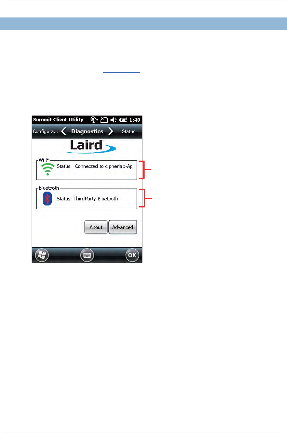
87
Chapt er 4 Using 802. 11 Radio
4.1. 4. DIAGNOSTICS TABBED PAGE
Perform diagnost ic test s to troubleshoot connect ion issues when necessary.
To open the Diagnost ics page:
1 . Open SCU as described in Launch SCU.
2 . Tap the D ia gn ostics tab t o show t he Diagnost ics page.
Diagnost ics st atus for Wi- Fi and Bluetoot h shows, along wit h on- screen but t ons
to open Advanced set tings and view software version inform at ion.
Wi- Fi diagnostics st atus
Bluet oot h diagnost ics st atus
( service not available now)
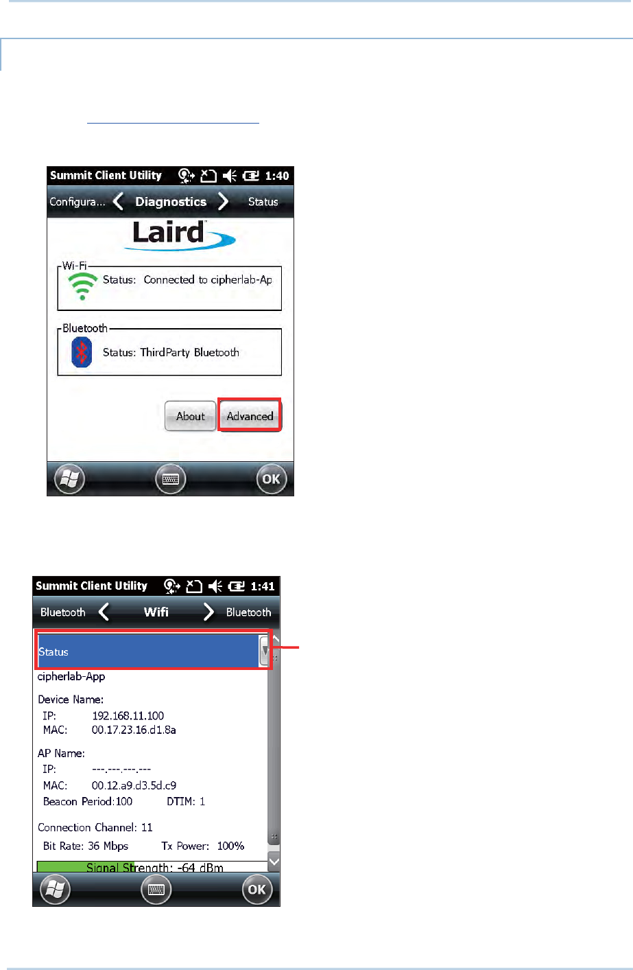
88
9200 Mobile Comput e
r
Ref erence Manual
ADVANCED DIAGNOSTICS
To access Advanced diagnost ics set tings:
1 . Open Diagnostics Tabbed Page.
2 . Tap the Adva nce d button to open advanced diagnost ics set tings.
CHECK STATUS
To check diagnostics status, select St a t u s in t he drop-down bar.
Select St at us to check
connect ion det ails
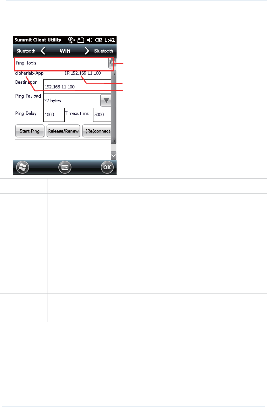
89
Chapt er 4 Using 802. 11 Radio
USE PING TOOLS
To perform ping t est s, select Ping Tools in t he drop- down bar.
Item Description
Dest inat ion Enter t he address to ping.
Ping Payload The am ount of dat a to be t ransm itt ed on a ping.
Value: 32, 64, 128, 256, 512, 1024
Default: 32 (bytes)
Ping Delay The am ount of t im e that elapses bet ween successive ping requests.
Value: 0~ 7200000
Default: 1000 ( m illiseconds)
Tim eout m s The am ount of t im e that elapses wit hout a response before ping request is
considered a failur e.
Value: 0~ 30000
Default: 5000 ( m illiseconds)
St art Ping Enter the address to ping to in the D e st in at io n field and tap St a rt Pin g. A
cont inuous ping will begin until the following happens: St op Ping is t apped, t he,
the application is exited, or t he radio is rem oved. Act ivity st atus will be logged in
the output box below.
Select Ping Tools to diagnose
the connect ion
Device I P address
AP Nam e
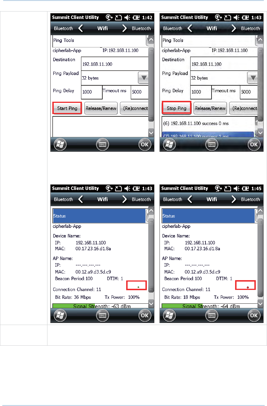
90
9200 Mobile Comput e
r
Ref erence Manual
St art Ping
When an active ping is initiat ed, the screen displays a ping indicator t hat blinks
in green (for a successful ping) or red (for an unsuccessful ping). The ping
indicat or is hidden when the screen is swit ched t o a t ab other t han Diags or
St atusˁ
Release/ Renew Obt ain a new I P address t hrough DHCP release/ renew, and log all act ivit y in t he
output area at t he bott om .
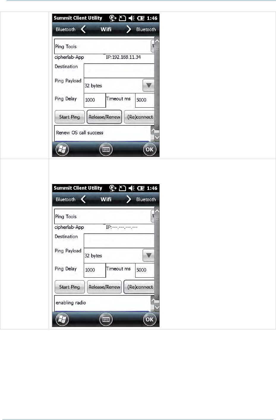
91
Chapt er 4 Using 802. 11 Radio
( Re) connect Disable and enable the radio, apply or re-apply t he current pr ofile, att em pt to
associat e and aut hent icate to t he wireless net work, and log all act ivit y in t he
output area at t he bott om .
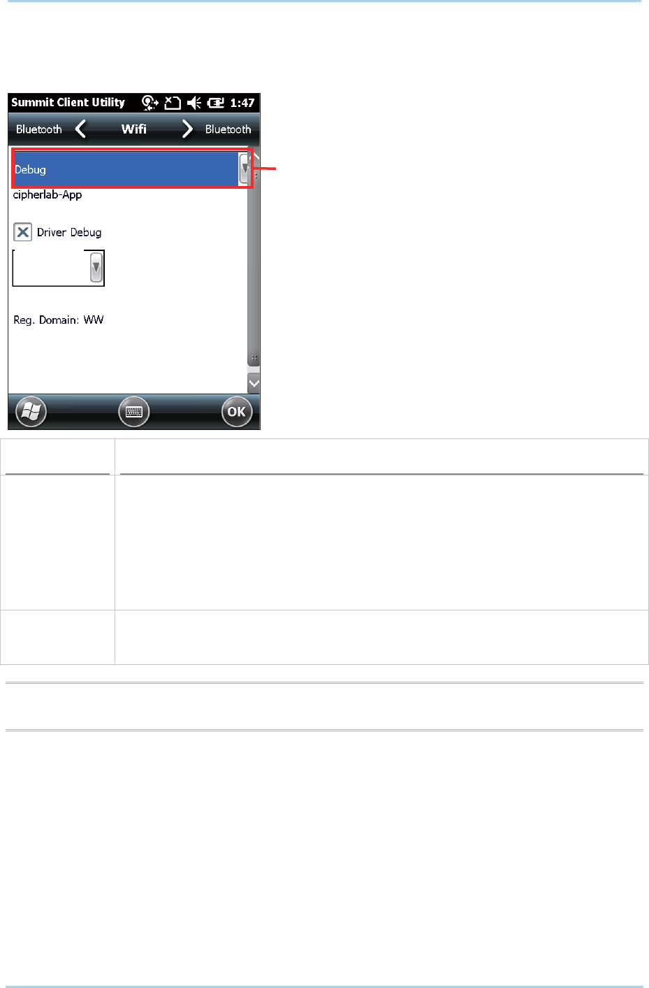
92
9200 Mobile Comput e
r
Ref erence Manual
USE DEBUG TOOLS
To check debug settings, select De bug in the drop- down bar.
Item Description
Driv er Debug Select whet her to debug t he WLAN driver, and t he out put m ode for driver debug.
Value: Not set, 1- Text( Low ), 2-Text , 3- Text (High), 4-Serial(Low ), 5-Serial,
6-Serial(High)
Default: Not set
When set as 1-Text( Low) , 2- Text , or 3- Text( High) , SCU w ill cont inue t o
export debug logs t o the m obile com puter’s internal storage. Do not select
any of these opt ions unless necessary.
Reg. Dom ain I ndicat es the regulatory dom ain or dom ains for which the radio is configured by
default . Default sett ing is “Worldw ide” , which m eans that t he radio can be used
in any dom ain.
Note: I t is recom m ended that Driver Debug out put set t ings are kept as default and not
changed.
Select Debug t o check debug
set tings
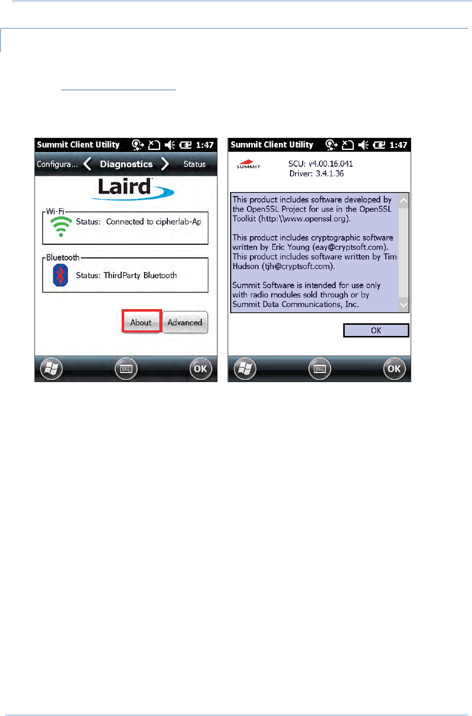
93
Chapt er 4 Using 802. 11 Radio
SOFTWARE VERSION INFORMATION
To check soft ware version inform at ion:
1 . Open Diagnost ics Tabbed Page.
2 . Tap the About but t on t o view inform at ion about SCU version, device driver, and
software developer.

94
9200 Mobile Comput e
r
Ref erence Manual

95
The 9200 Mobile Com put er lets you configure Bluetoot h settings and m anage Bluet ooth
services provided on rem ot e devices.
Bluetooth Profiles Supported
Serial Port Profile ( SPP) supports Server/ Client
Object Push Profile ( OPP) support s Ser ver/ Client
Dial-Up Net working Profile ( DUN) supports Client only
Personal Area Networking Profile ( PAN)
Hum an I nt erface Device Profile ( HI D) support s keyboard and m ouse wit hout cursor
Headset Profile ( HSP)
Hands- Free Profile ( HFP)
Generic Access Profile (GAP)
Generic Object Exchange Profile ( GEOP)
Advanced Audio Dist ribut ion Profile (A2DP)
Audio/ Video Rem ote Control Profile ( AVRCP)
Phone Book Access Profile ( PBAP)
ActiveSync- Over- Bluet oot h
IN THIS CHAPTER
5.1ʳBluetooth Power ........................................................ 96
5.2ʳSearch Devices .......................................................... 98
5.3ʳPair Devices .............................................................100
5.4 Serial Port Service ....................................................103
5.5 Object Push via Beam................................................107
5.6 ActiveSync via Bluet ooth............................................ 109
Chapter 5
USING BLUETOOTH
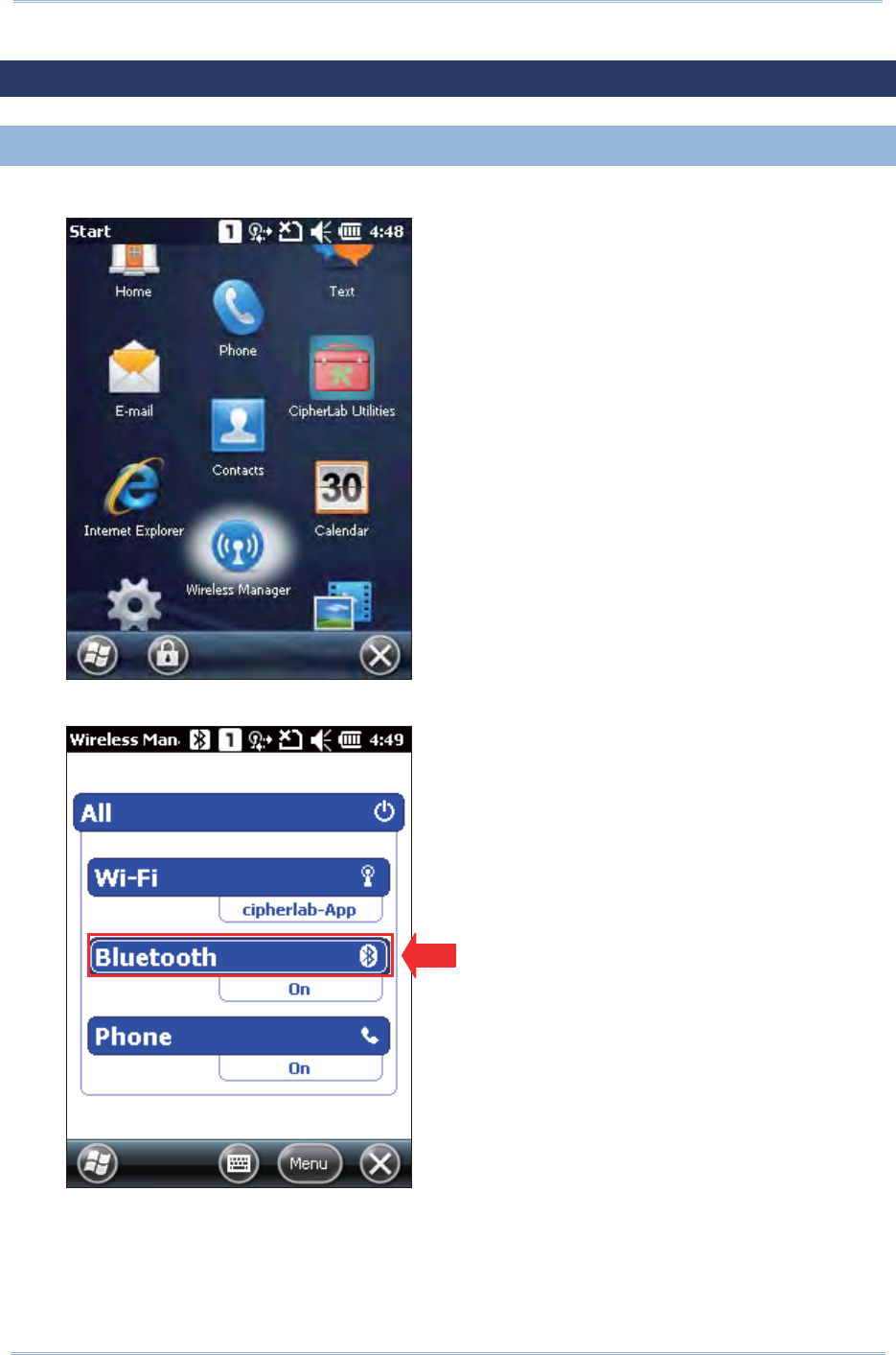
96
9200 Mobile Comput e
r
Ref erence Manual
5.1. BLUETOOTH POWER
5.1. 1. POWER ON BT VIA WIRELESS MANAGER
1 . Go to Star t Scre en | W ireless M ana ge r as shown below.
2 . Tap All or Blu et oot h t o t urn on t he power.
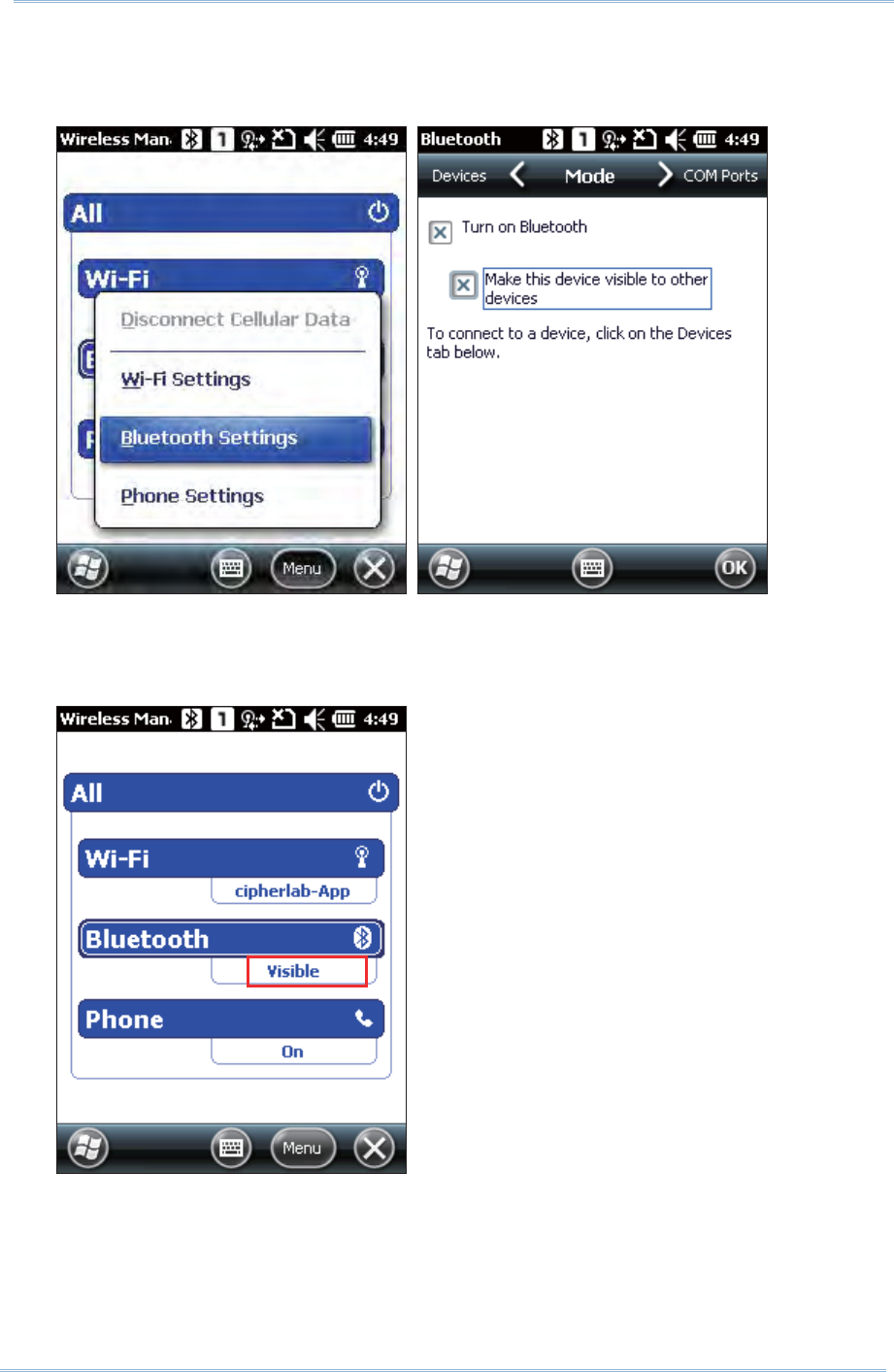
97
Chapt er 5 Using Bluet oot h
3 . To m ake t he m obile com puter discoverable to ot her Bluet ooth devices, tap Me nu
| Bluet oot h Set t ings | Mode t ab, and check “ Make this device visible to ot her
devices” . Tap OK t o confirm .
4 . The Bluet ooth status becom es “Visible” under Wireless Manager, m eaning
Bluetoot h is turned on and deploym ent is enabled.
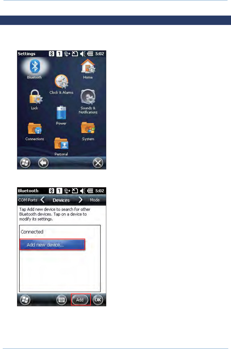
98
9200 Mobile Comput e
r
Ref erence Manual
5.2. SEARCH DEVICES
1 . I n t he Bluet ooth configurat ions screen, on t he Devices m ode t ab you can search
for other Bluet ooth device or go to St a rt Screen | Set tings | Blue t ooth for t he
sam e set t ings.
2 . Tap Add new device…or Add on the softkey bar t o search for ot her Bluet ooth
devices.
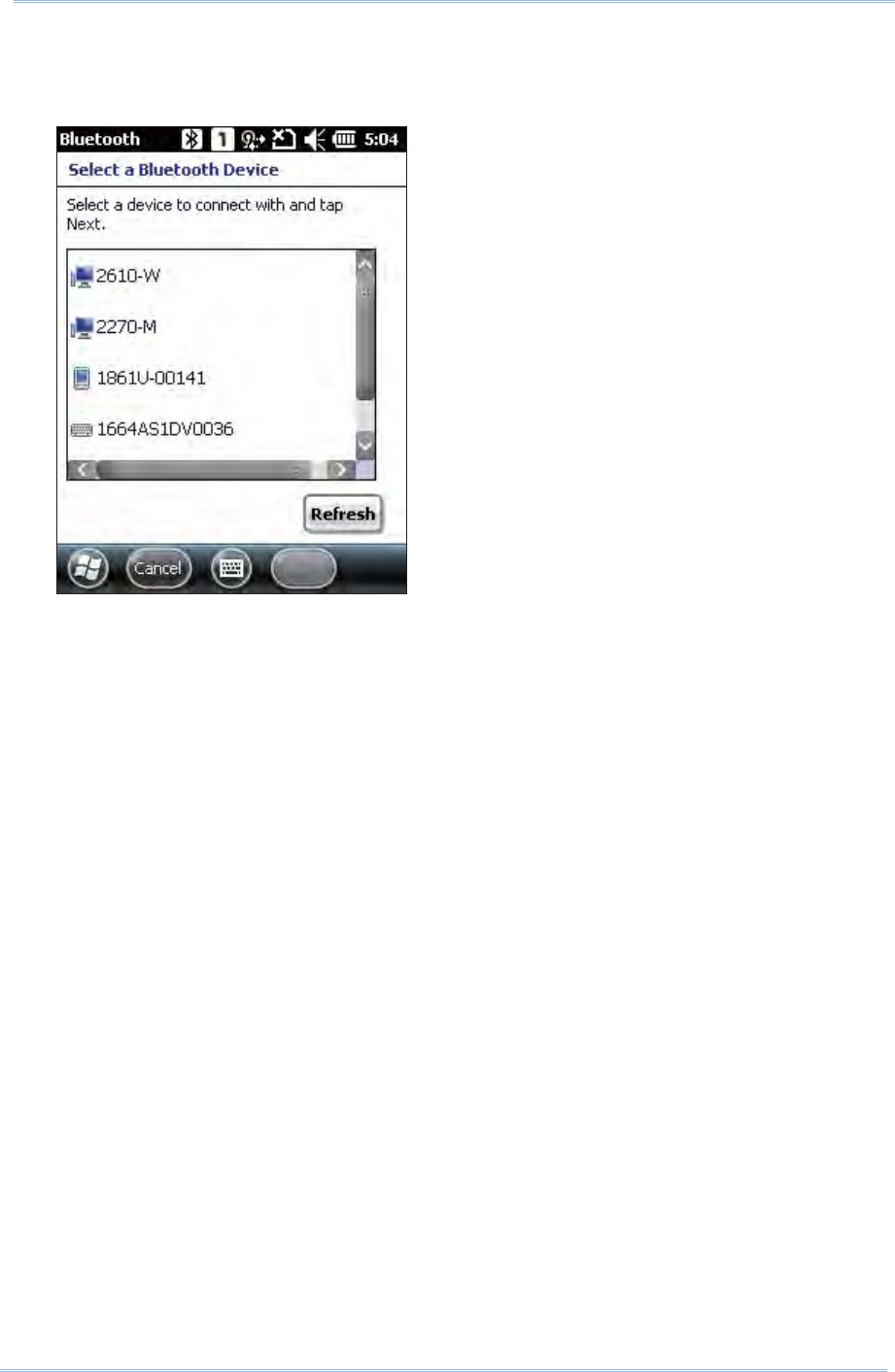
99
Chapt er 5 Using Bluet oot h
3 . Wait for a few seconds, and it will list the discovered devices. I f you do not see
the device t hat you wish to connect , m ake sure it is set as discoverable. Tap
Re fresh to search again.
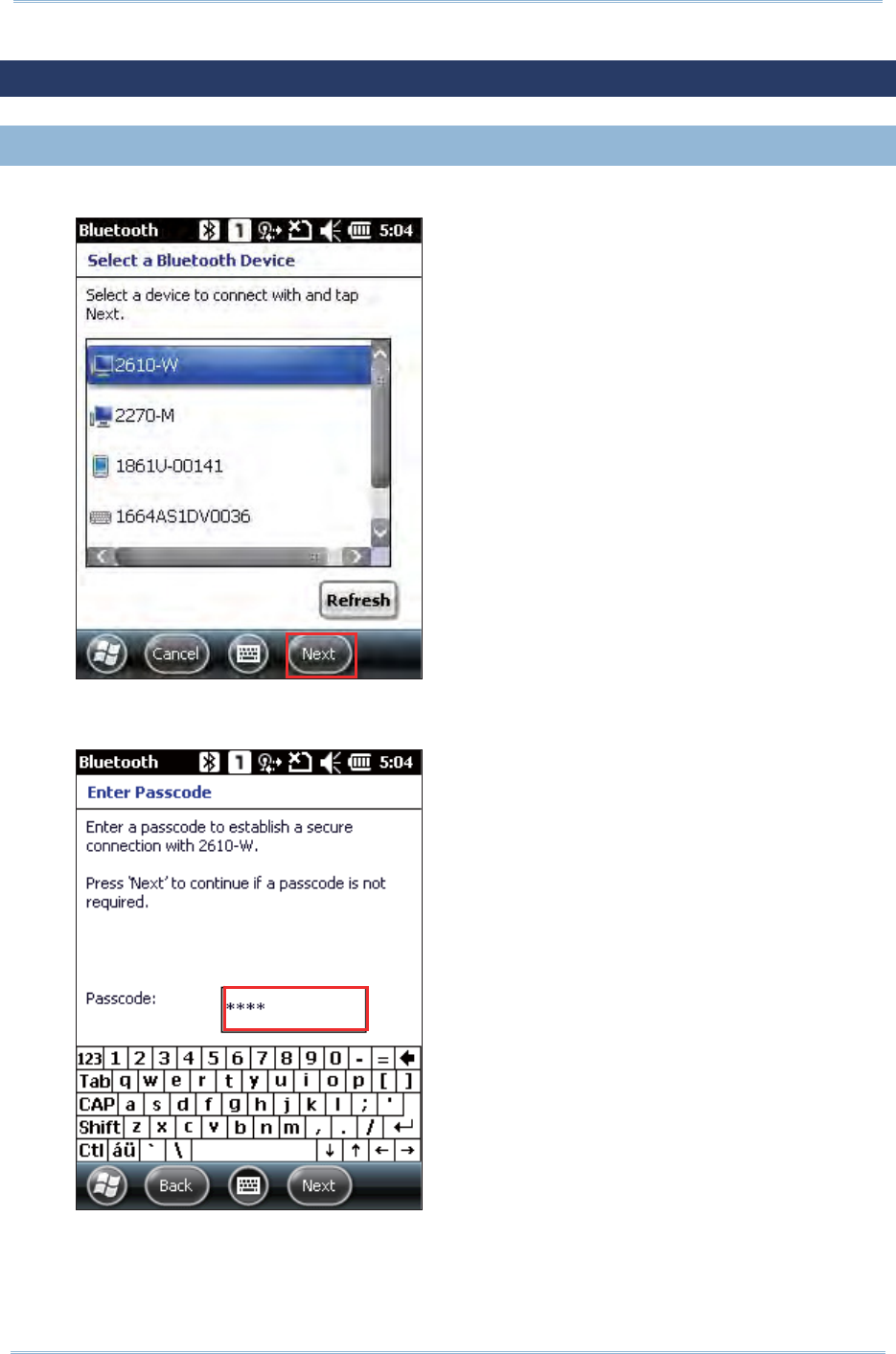
100
9200 Mobile Comput e
r
Ref erence Manual
5.3. PAIR DEVICES
5.3. 1. PAIR
1 . Select a device to connect and t ap N e x t .
2 . I f necessary, ent er the password t o establish a secure connection. Make sure a
consist ent password is ent ered on bot h devices. Tap N ex t .
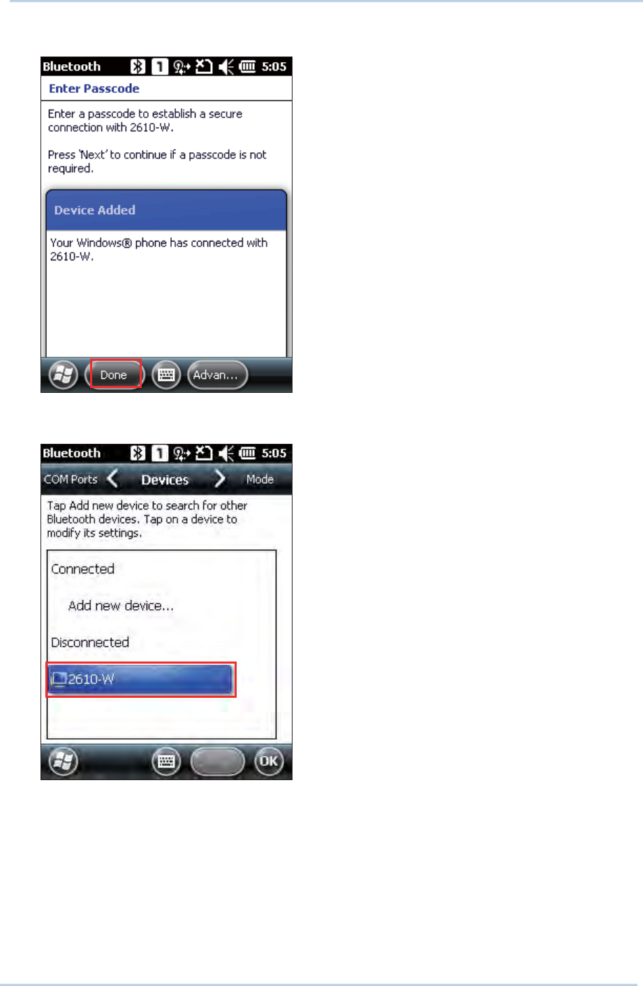
101
Chapt er 5 Using Bluet oot h
3 . The two devices becom e connected via Bluetoot h. Tap D one .
4 . Once paired successfully, the device will appear in the device list . Tap it to view
available Bluet ooth services or m odify its display nam e.
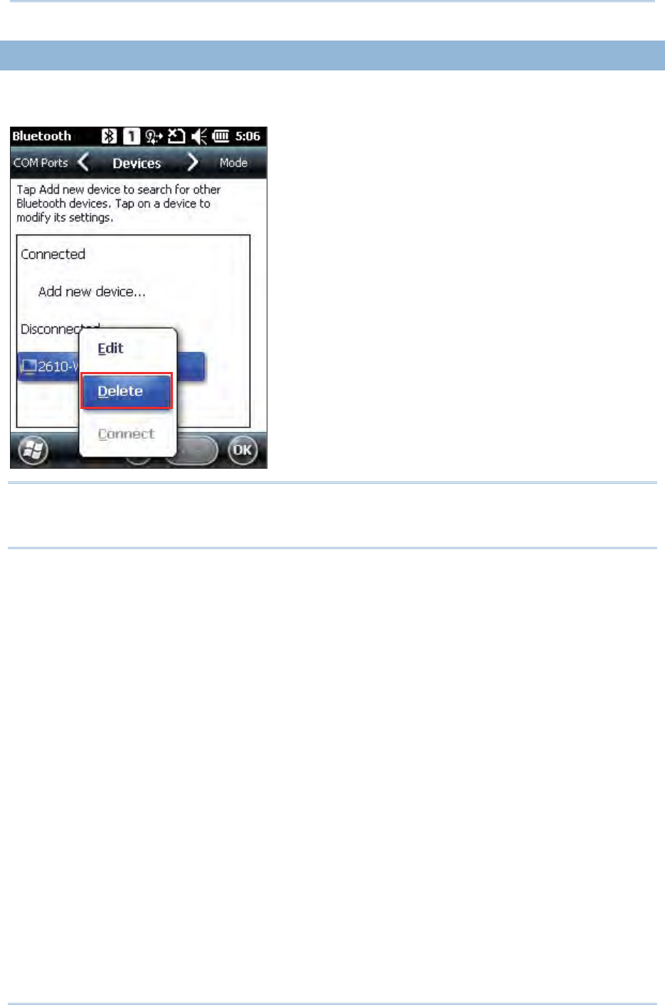
102
9200 Mobile Comput e
r
Ref erence Manual
5.3. 2. UNPAIR
On the Devices t ab, t ap and hold t he desired device t o select De let e from the pop-up
m enu.
Note: The m obile com puter m ust be unpaired on t he rem ot e device as well. Rem ove it
from the device list on t he rem ot e device as well. (Both devices m ust be unpaired
and rem oved!)
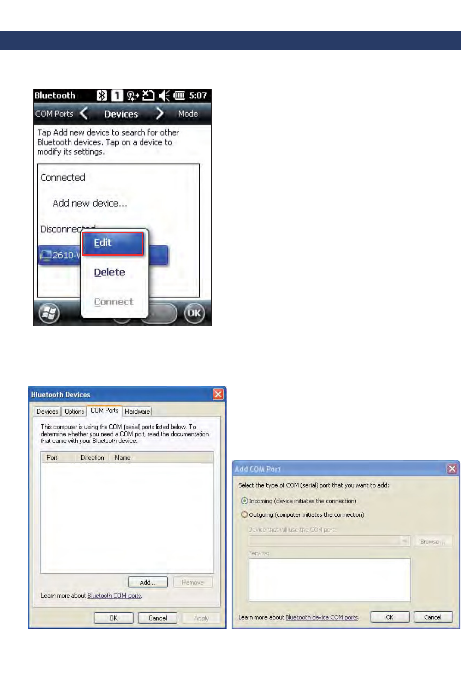
103
Chapt er 5 Using Bluet oot h
5.4. SERIAL PORT SERVICE
1 . On t he Devices tab, tap and hold the desired device t o select Edit from t he pop- up
m enu.
2 . Make sure t he Serial Port service is enabled for use on t he rem ot e Bluetoot h device.
For PC exam ple, you can launch the Bluet ooth Device configurat ion utility and in the
Bluetooth Device configuration screen, t ap COM Ports tab, tap Add as below. Select
“ I ncom ing ( device initiat es the connect ion)” item t ap OK.
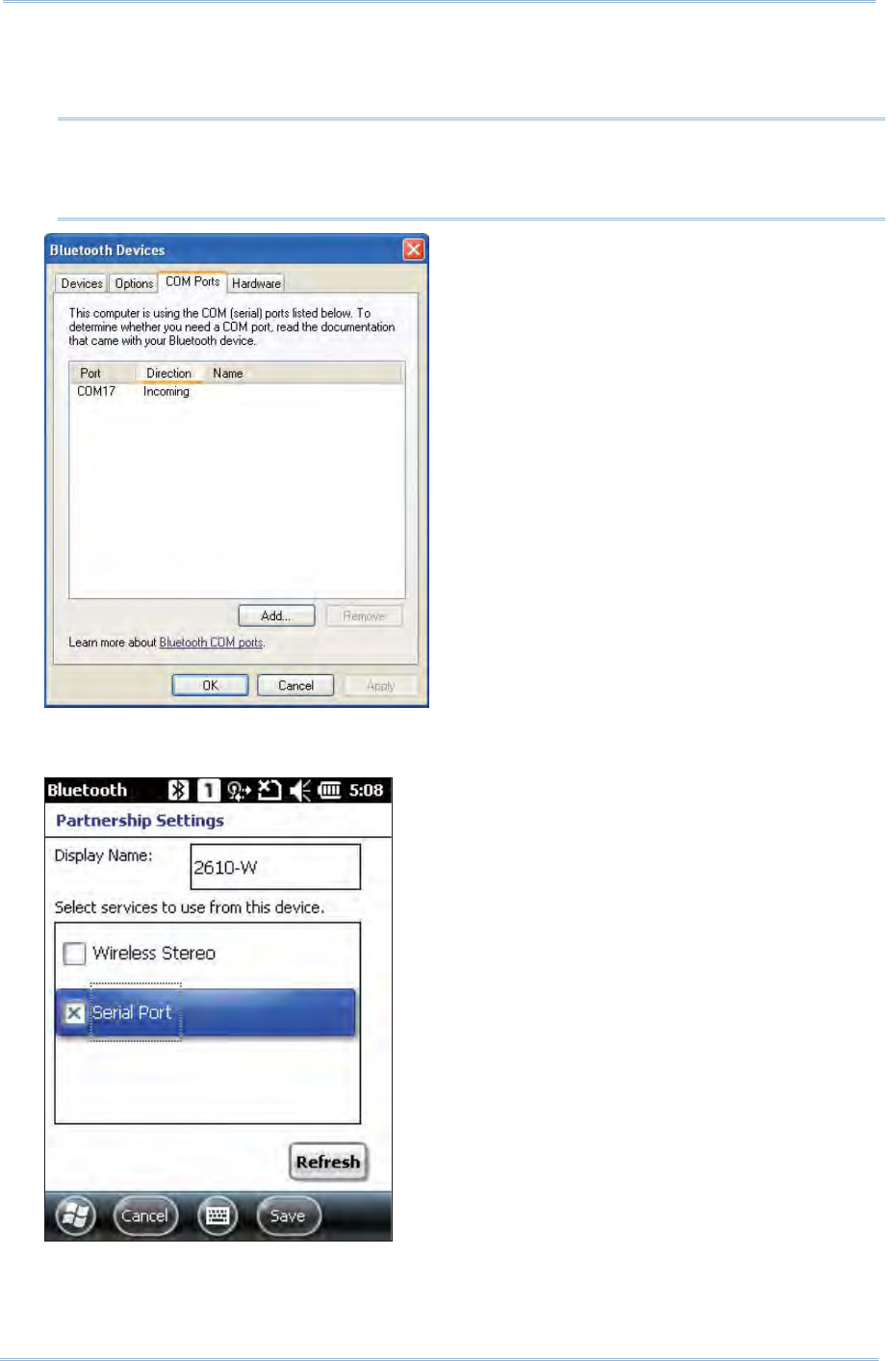
104
9200 Mobile Comput e
r
Ref erence Manual
3 . The searched COM port will be showed on t he screen, select the connect ed COM port
then tap OK.
4 . On t he Bluetoot h configuration screen of t he m obile com puter, t ap Refr esh to select
Serial Port check box, click Save.
Note: On t he PC, you can use applicat ions such as HyperTerm inal to confirm t he
connect ion between your PC and m obile com puter. I n HyperTerm inal, the COM port
No. has t o be set exactly as the incom ing port No. on your PC.
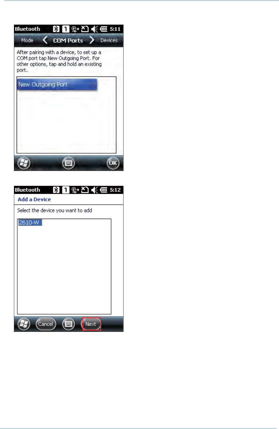
105
Chapt er 5 Using Bluet oot h
5 . On t he COM Ports t ab, tap N ew Out going Port .
6 . Select t he rem ot e device, and t hen tap N e xt .
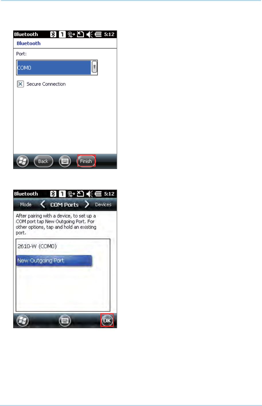
106
9200 Mobile Comput e
r
Ref erence Manual
7 . Select a COM port, and t hen tap Finish. ( For Bluet ooth, please select COM0 or COM3
for connect ion.
8 . A new Bluet ooth serial port is creat ed. Tap OK. The m obile com puter is ready to
transm it data via Bluetoot h.
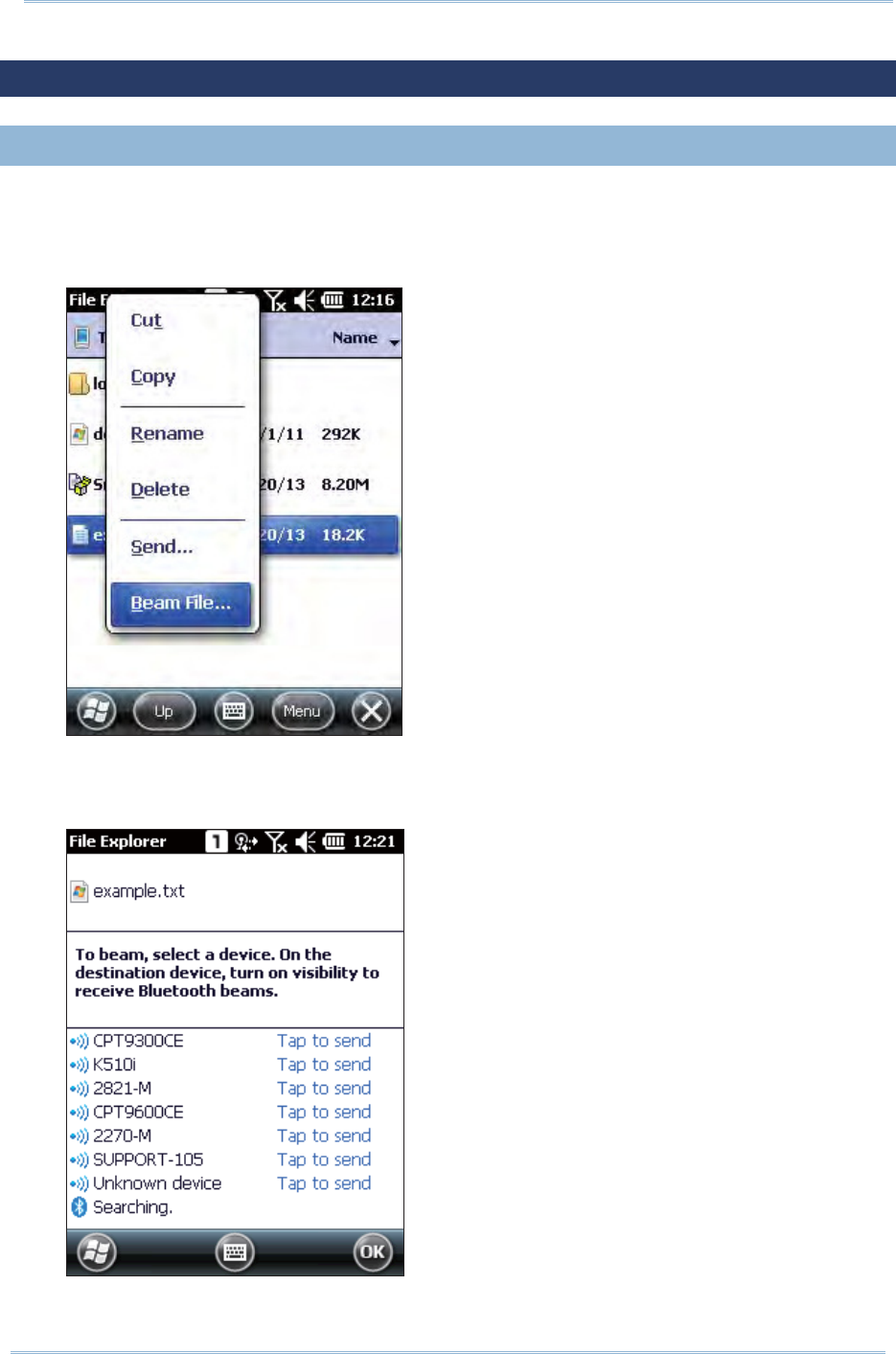
107
Chapt er 5 Using Bluet oot h
5.5. OBJECT PUSH VIA BEAM
5.5. 1. SEND A FILE
1 . Tap Sta r t Scr een | File Explorer .
2 . Navigat e to the folder cont aining the file you wish to send t o t he Bluetoot h device.
3 . Tap and hold the file and select Beam file from the pop- up m enu.
4 . Tap the rem ot e device of int erest to send t he file via Bluet ooth. The m obile
com puter will start uploading the file. The rem ot e device will st art receiving t he
file few seconds lat er. When file transfer is com plet ed, tap OK t o exit
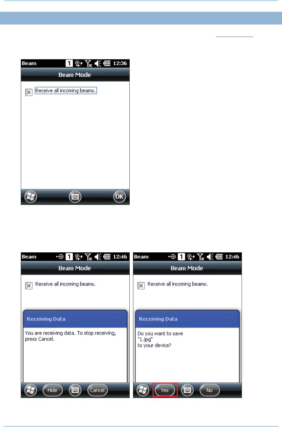
108
9200 Mobile Comput e
r
Ref erence Manual
5.5. 2. RECEIVE A FILE
1 . Pair the m obile com puter will the rem ote device as described in Pair Devices.
2 . Tap Star t Scre en | Se t t in gs | Connections | Beam , and m ak e sure “ Receive all
incom ing beam s” is enabled in order to receive incom ing files.
3 . On the rem ote device, send a desired file to the m obile com put er via Bluet ooth.
4 . A “ Receiving Data” dialog appears on- screen, first not ifying t hat t he m obile
com puter is receiving dat a, and then asking for confirm at ion t o save t he data. Tap
Yes t o continue. The received dat a will be st ored under \ M y Device\ My
Docum ents.
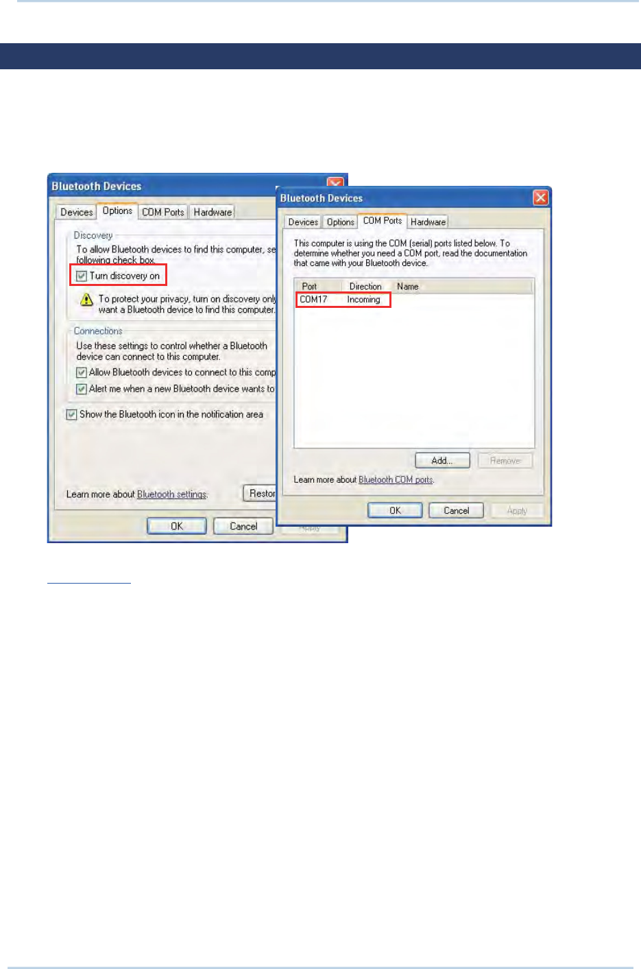
109
Chapt er 5 Using Bluet oot h
5.6. ACTIVESYNC VIA BLUETOOTH
To use Bluet ooth via ActiveSync, first configure Bluet ooth set tings correctly on your
com puter first.
1 . Configure Bluetoot h sett ings for your com put er, such as “Turn discovery on” and
add a COM port (incom ing) , t he COM port value depending on your com puter.
2 . Pair the m obile com puter wit h the rem ote com puter via Bluet ooth as described in
Pair Devices.
3 . For Bluet ooth connection to work via Act iveSync, eit her disconnect physically by
detaching the m obile com puter from the Snap- on Cable or Cradle, or uncheck the
“ Allow USB connections” opt ion under Act ive Syn c | File | Connect ion Settin gs.
I n addit ion, enable COM port connection and specify t he correct COM port.
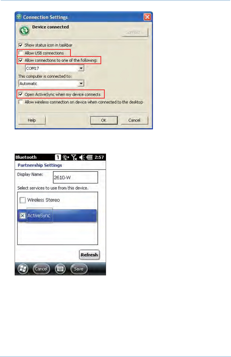
110
9200 Mobile Comput e
r
Ref erence Manual
4 . Aft er Act iveSync service is set on the rem ot e com puter, enable ActiveSync service
on the m obile com puter’s Bluet oot h part nership set t ings. Tap Re fresh if the
option does not appear in t he list.
4 . On the m obile com puter, tap St a rt Scr een | Act ive Sy nc | M enu and select
Connect via Blue tooth in t he option m enu. ActiveSync partnership will be
est ablished between the rem ot e com puter and m obile com puter via Bluet ooth
after a few seconds.

111
The 9200 Mobile Com put er allows m aking phone calls and connect ing t o t he network
over General Packet Radio Service (GPRS) . I nsert t he SI M card before turning on t he
power. Refer t o I nsert ing SI M Card.
Note: I f t he SI M card is not in position, you m ay m ake em ergency calls if the service is
support ed.
IN THIS CHAPTER
6.1ʳPhone Power ............................................................ 112
6.2ʳPhone Application...................................................... 115
6.3ʳPhone Set t ings ......................................................... 118
6.4ʳMaking Phone Calls ...................................................122
6.5ʳConfiguring GPRS Network .........................................127
Chapter 6
USING THE PHONE
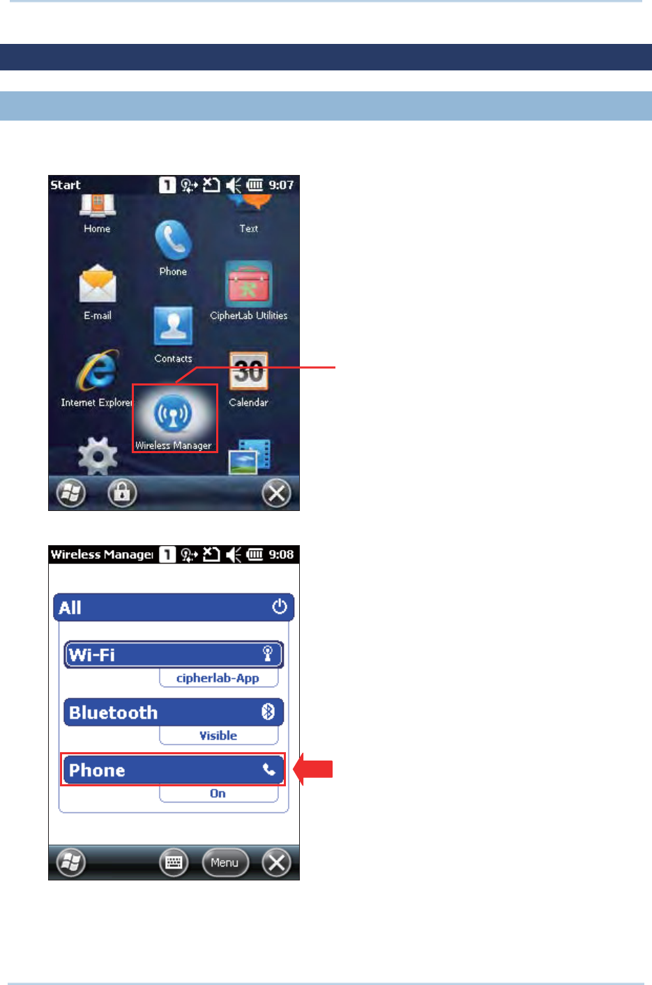
112
9200 Mobile Comput e
r
Ref erence Manual
6.1. PHONE POWER
6.1. 1. POWER ON PHONE VIA WIRELESS MANAGER
1 . Phone power is t urned on by default . I f not , go to St a rt Scr een | W ireless
Manager t o access W ire less Manager.
2 . Tap All or Phone t o turn on the power.
Wireless Manager
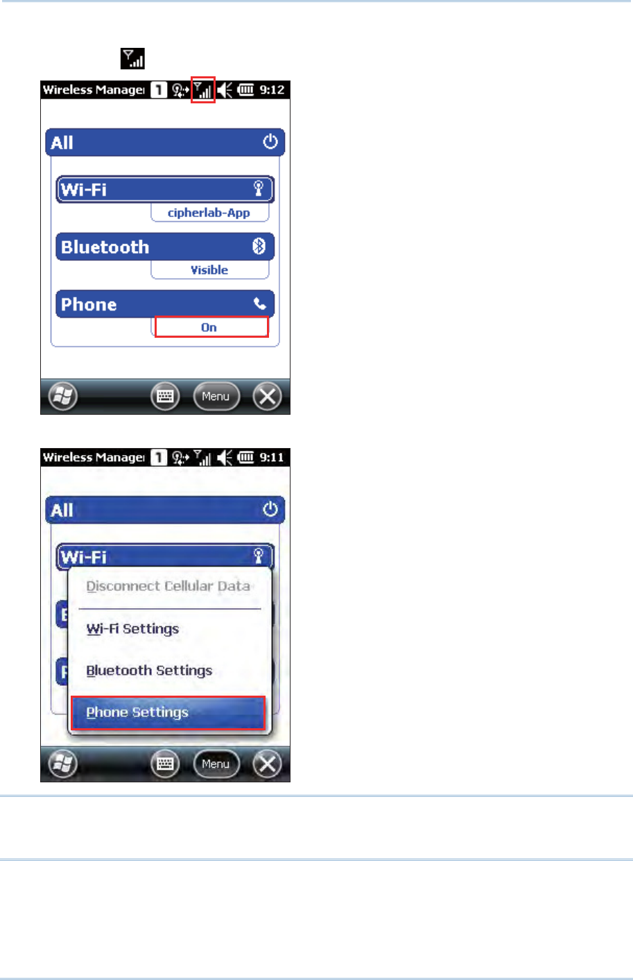
113
Chapt er 6 Using t he Phone
3 . When the power is turned on, t he Phone status appears as “ On”, and an ant enna
signal icon will be displayed on t he t it le bar.
4 . Tap Menu | Phone Se t t ings to configure relat ed set t ings if necessary.
Note: Phone Set t ings are only available when the phone power has been turned on. You
can check the security set t ings, change the PI N code on your SI M card and so on if
necessary.
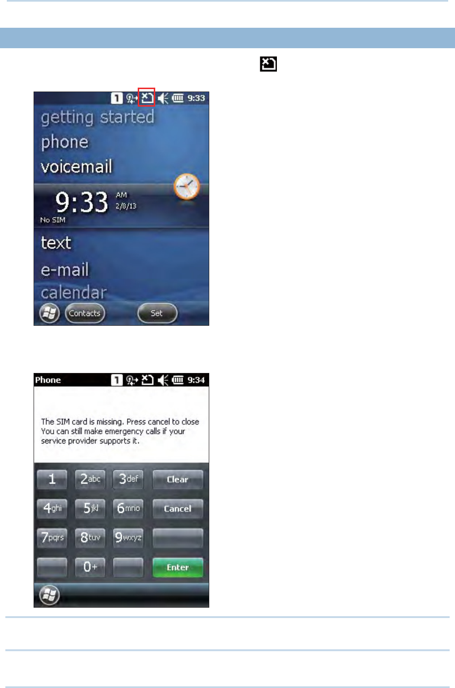
114
9200 Mobile Comput e
r
Ref erence Manual
6.1. 2. SIM CARD MISSING
1 . On the Hom e Scree n, t he not ification icon on the t it le bar shows that t he
SI M card is m issing.
2 . Tap Phone or press the [ SEND] but t on on t he physical keypad t o access t he
phone applicat ion. I f support ed by your service provider, only em ergency calls are
allowed when a SI M card is absent.
Note: I f your wired headset ( CTI A st andard) has an integrat ed hook swit ch, press the
hook switch to open the dialer screen.
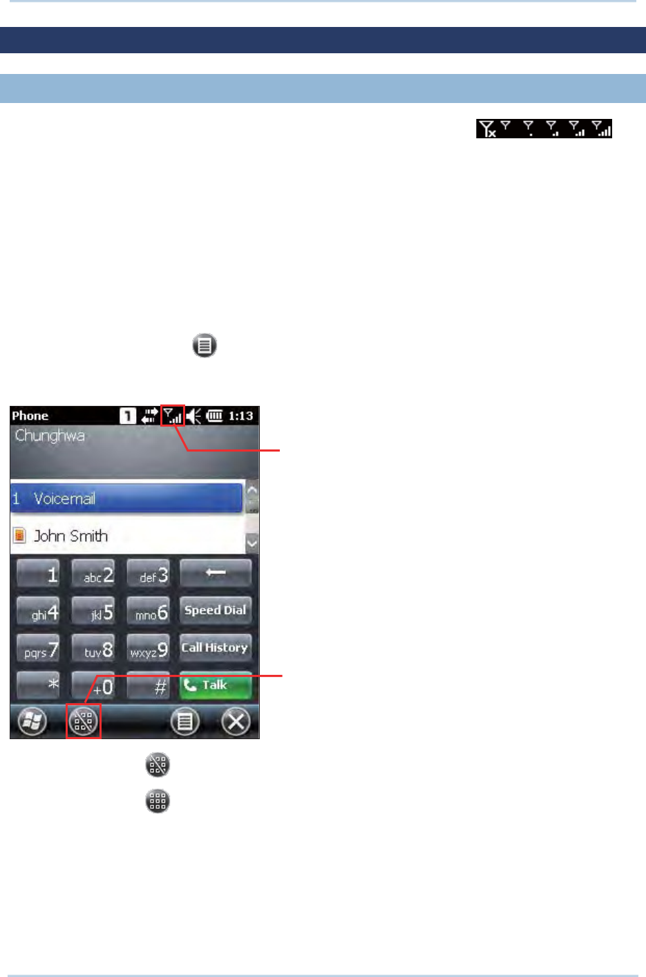
115
Chapt er 6 Using t he Phone
6.2. PHONE APPLICATION
6.2. 1. PHONE INTERFACE
Aft er t he phone applicat ion is launched, t he antenna signal icon on
the title bar indicates whet her you are connected t o your service provider’s net work. As
the st rengt h of t he signal dim inishes, so will t he num ber of bars in the icon, which ranges
from no signal to excellent signal ( four- bars) .
The display panel on the t op half of the screen is used t o show your service provider’s
nam e and the cont act nam e and/ or phone num ber when m aking or receiving a call.
Tap the scroll bar next to t he display panel to browse call history, which keeps a
record of t he phone num bers dialed in and out, as well as m issed phone calls.
Tap a cont act nam e t o view, edit the cont act det ails, send or beam contact info, or
add cont act t o speed dial list.
Tap the M enu but t on on the soft key bar to switch the view opt ions.
The phone keypad is displayed for telephone num ber input or speed dial.
Tap the button (Hide keypad) on t he softkey bar t o hide the keypad.
Tap the button (Show keypad) on t he softkey bar t o show the keypad.
Antenna signal icon
Show or hide
phone keypad
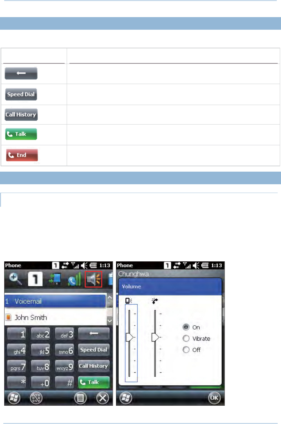
116
9200 Mobile Comput e
r
Ref erence Manual
6.2. 2. BUTTONS
The phone keypad feat ures t he following but t ons:
Button Description
[ Backspace] but t on allows you to delete t he last input.
[ Speed Dial] but t on allows you t o view, edit the speed dial list and
pick the num ber you want t o call.
[ Call Hist ory] but t on allows you to browse, edit call hist ory and pick
the num ber you want to call.
[ Talk] butt on allows you to m ake or receive a call.
Alt ernatively, you m ay press [ SEND] on the physical keypad.
[ End] butt on allows you to hang up a call.
Alt ernatively, you m ay press [ END] on the physical keypad.
6.2. 3. VOLUME
SYSTEM AND RINGER VOLUME
Tap the speaker icon in t he tit le bar drop- down list to change syst em volum e or phone
ringer volum e. You m ay also m ut e it or have it set as vibrate inst ead. An on-screen
gauge will appear to indicat e t he current set t ings.
Volum e adj ust m ent can also be done by pressing the volum e up/ down buttons on the
right side of t he m obile com puter.
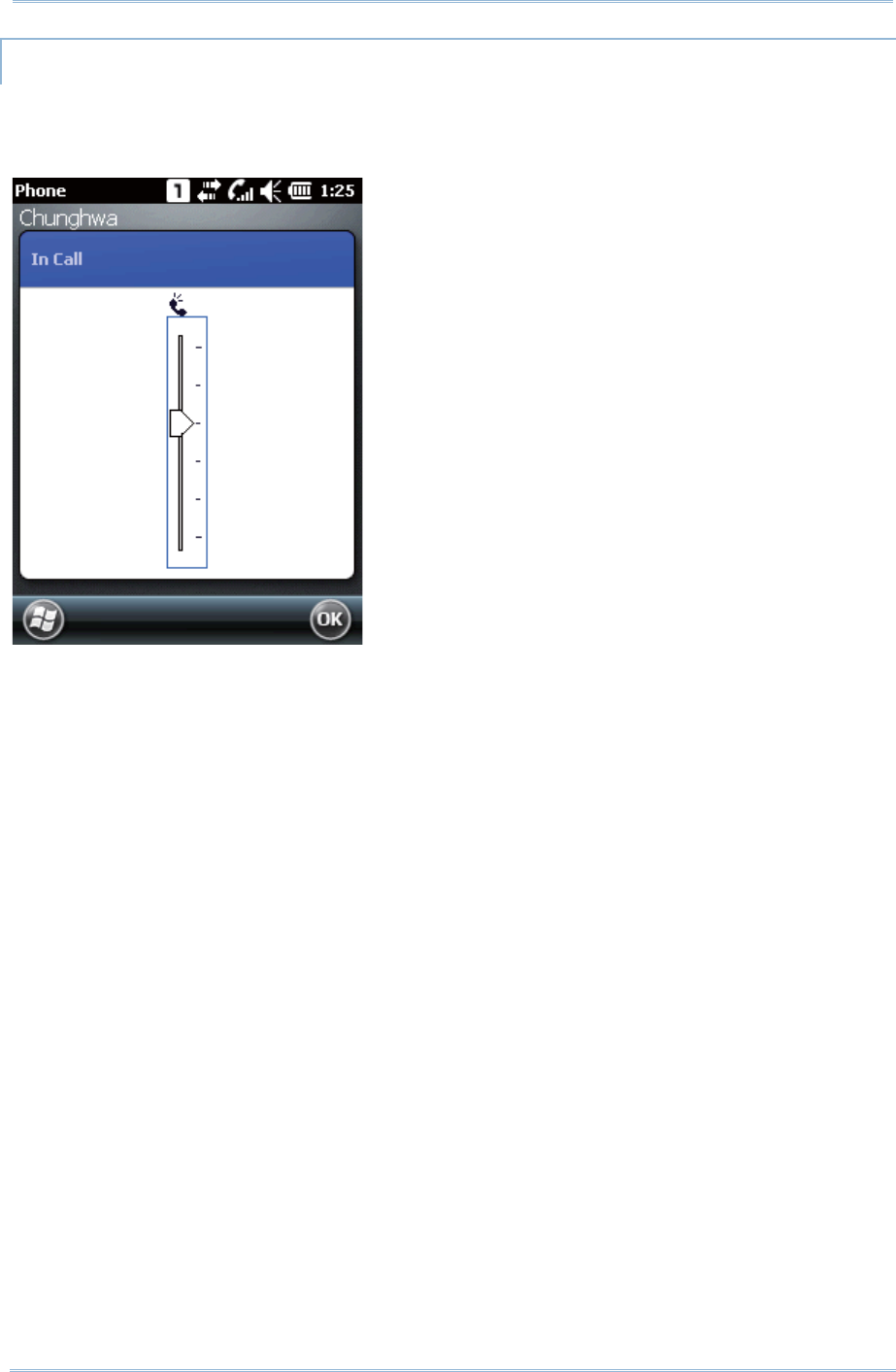
117
Chapt er 6 Using t he Phone
IN-CALL VOLUME
During a call, you can adjust the in-call volum e by tapping t he speaker icon in the t itle
bar drop- down list, or by pressing the volum e buttons on the right side of t he m obile
com puter. An on- screen gauge will appear to indicat e t he current volum e.
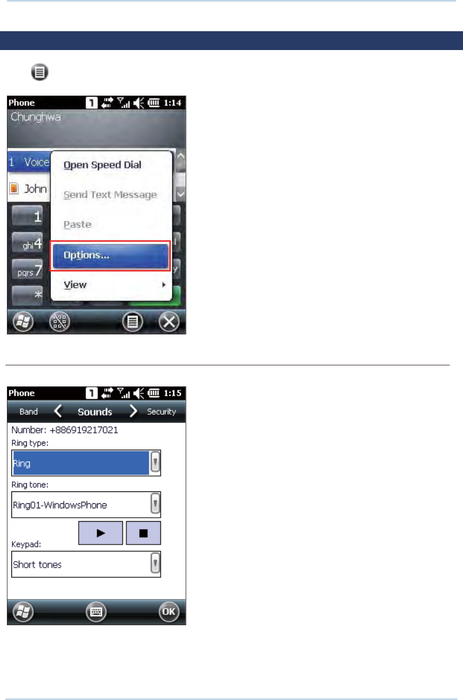
118
9200 Mobile Comput e
r
Ref erence Manual
6.3. PHONE SETTINGS
Tap M e nu | Opt ions to configure phone set t ings if necessary.
Sounds tab
Tap the Sounds tab t o adj ust phone ring t ype, ring tone, and keypad sound.
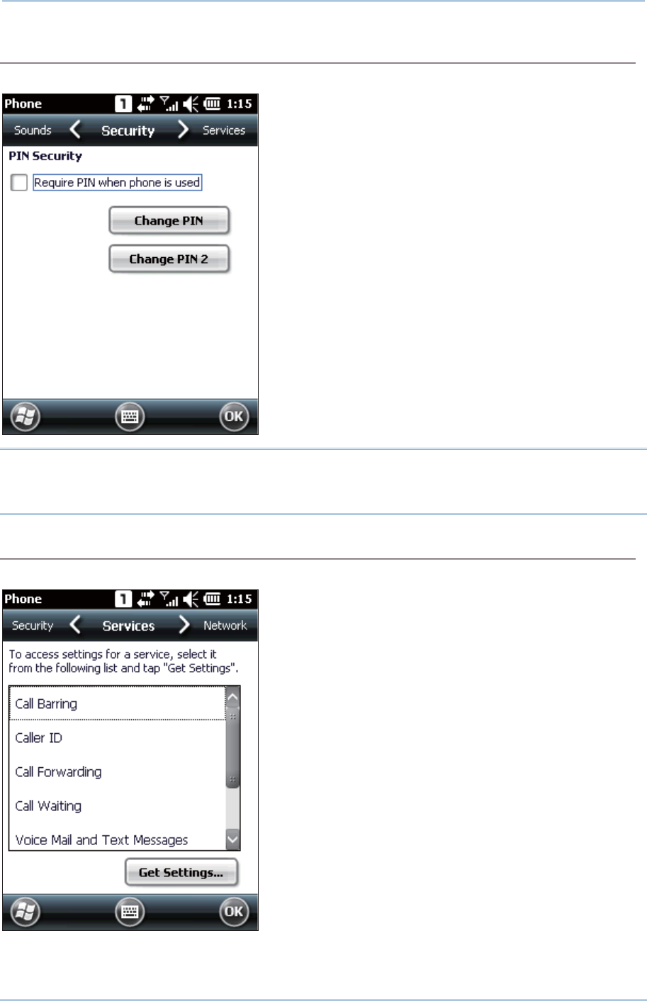
119
Chapt er 6 Using t he Phone
Security tab
Tap the Security tab t o change SI M card security and PI N code setting.
Note: The PI N verificat ion on the m obile com puter allows three chances t o input the
correct PI N code. I f input fails three tim es, t he SI M card will be locked, and you
will need to obt ain the PUK code from your net work operator t o unlock it
Services tab
Tap the Services tab t o get phone service set t ings from your network operat or.
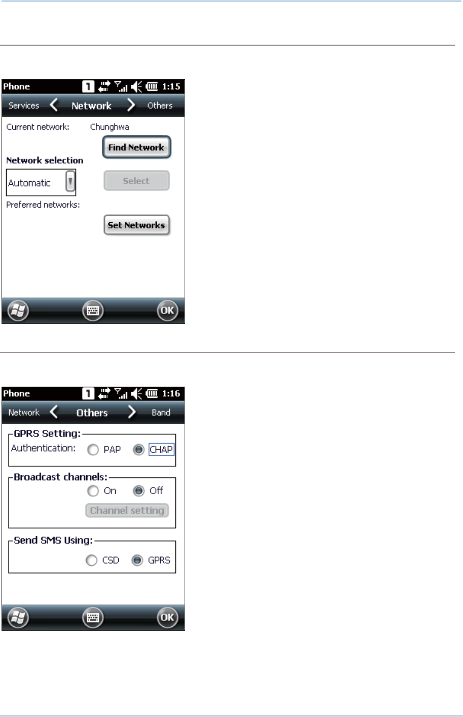
120
9200 Mobile Comput e
r
Ref erence Manual
Network tab
Tap the Network tab t o change phone net work settings and edit your preferred
networks.
Others tab
Tap the Others t ab to configure GPRS authentication type, broadcast channels, and
SMS transm ission set t ings.
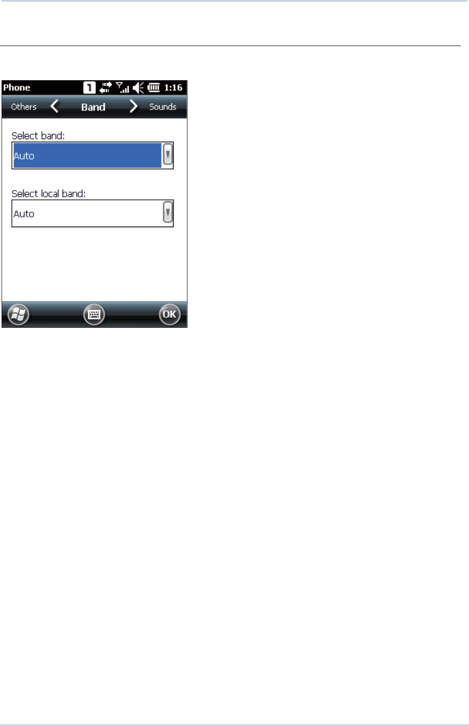
121
Chapt er 6 Using t he Phone
Band tab
Tap the Band t ab t o change t he band type and the local band in your geographic
region.
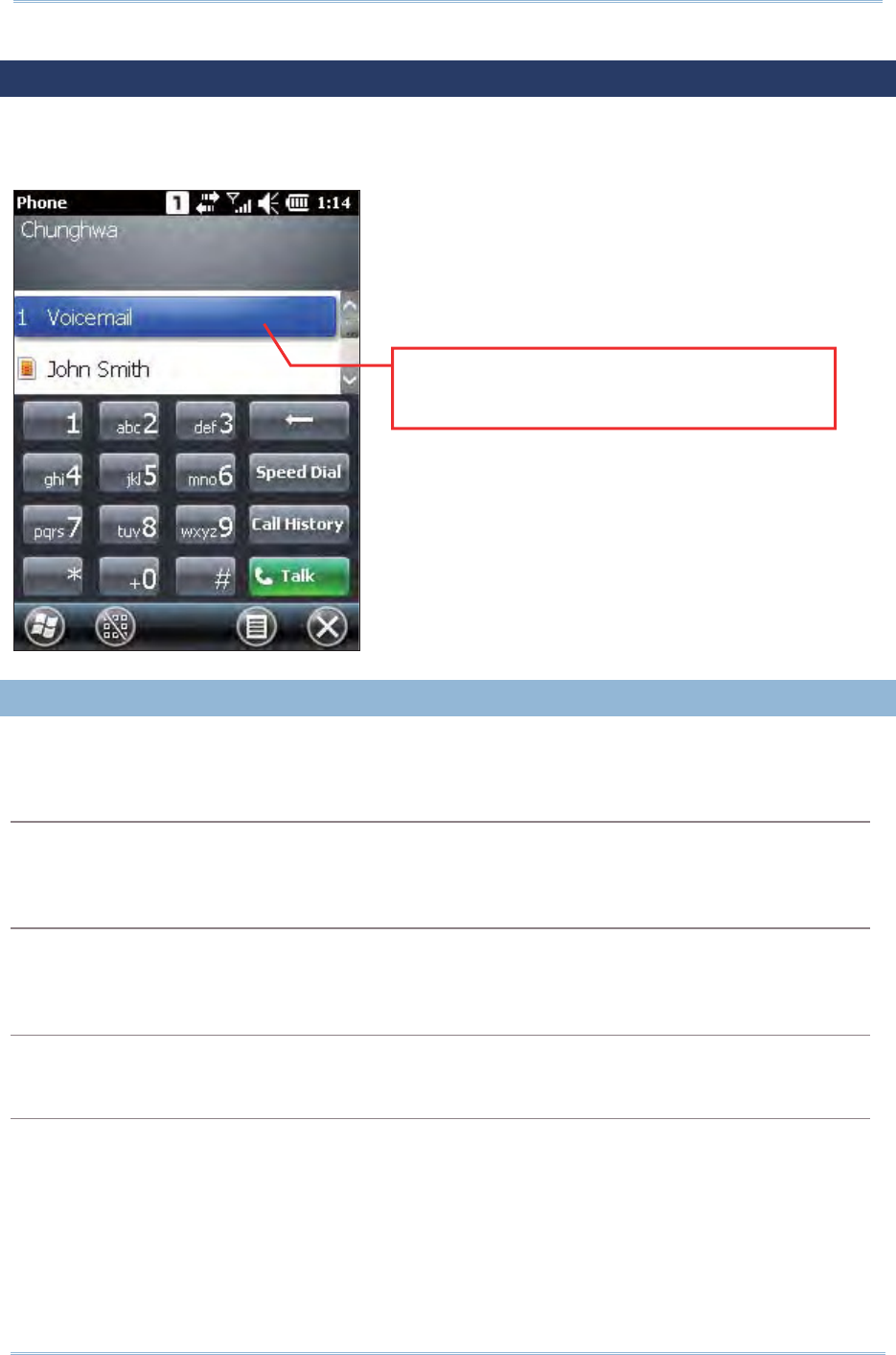
122
9200 Mobile Comput e
r
Ref erence Manual
6.4. MAKING PHONE CALLS
The phone feat ures allow you t o m ake or receive phone calls and assign a Speed Dial
num ber t o a contact.
6.4. 1. DIAL A NUMBER
You can dial a num ber by any of t he following ways:
Dialling
Use the dial pad on the screen or t he physical keypad – sim ply ent er the num ber you
want t o call.
From Contacts
Browse the cont act list via the display panel to find t he cont act or num ber you want to
call.
Using Speed Dial
Ent er t he speed dial num ber of the desired cont act .
From Call History
Browse call hist ory via t he display panel to pick t he number you want to call.
“1” indicates the reserved Speed Dial
number for the contact (or Voicemail)
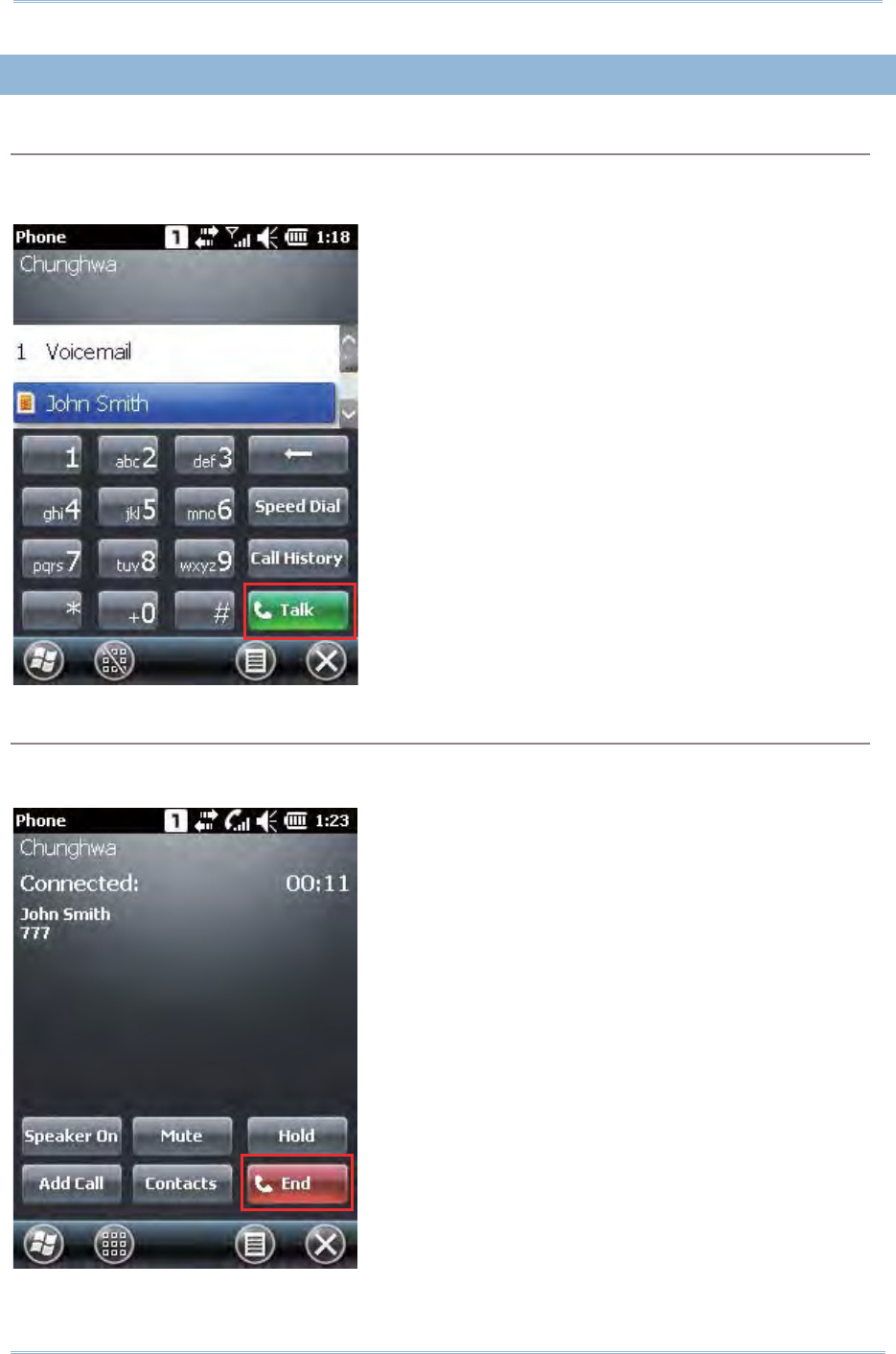
123
Chapt er 6 Using t he Phone
6.4. 2. MAKE A CALL
Dialling Out
Tap the green [ Talk] butt on on t he phone keypad, or press [ SEND] from the physical
keypad.
Hanging up
Tap the red [ End] but t on on t he phone keypad, or press [ END] from the physical
keypad.
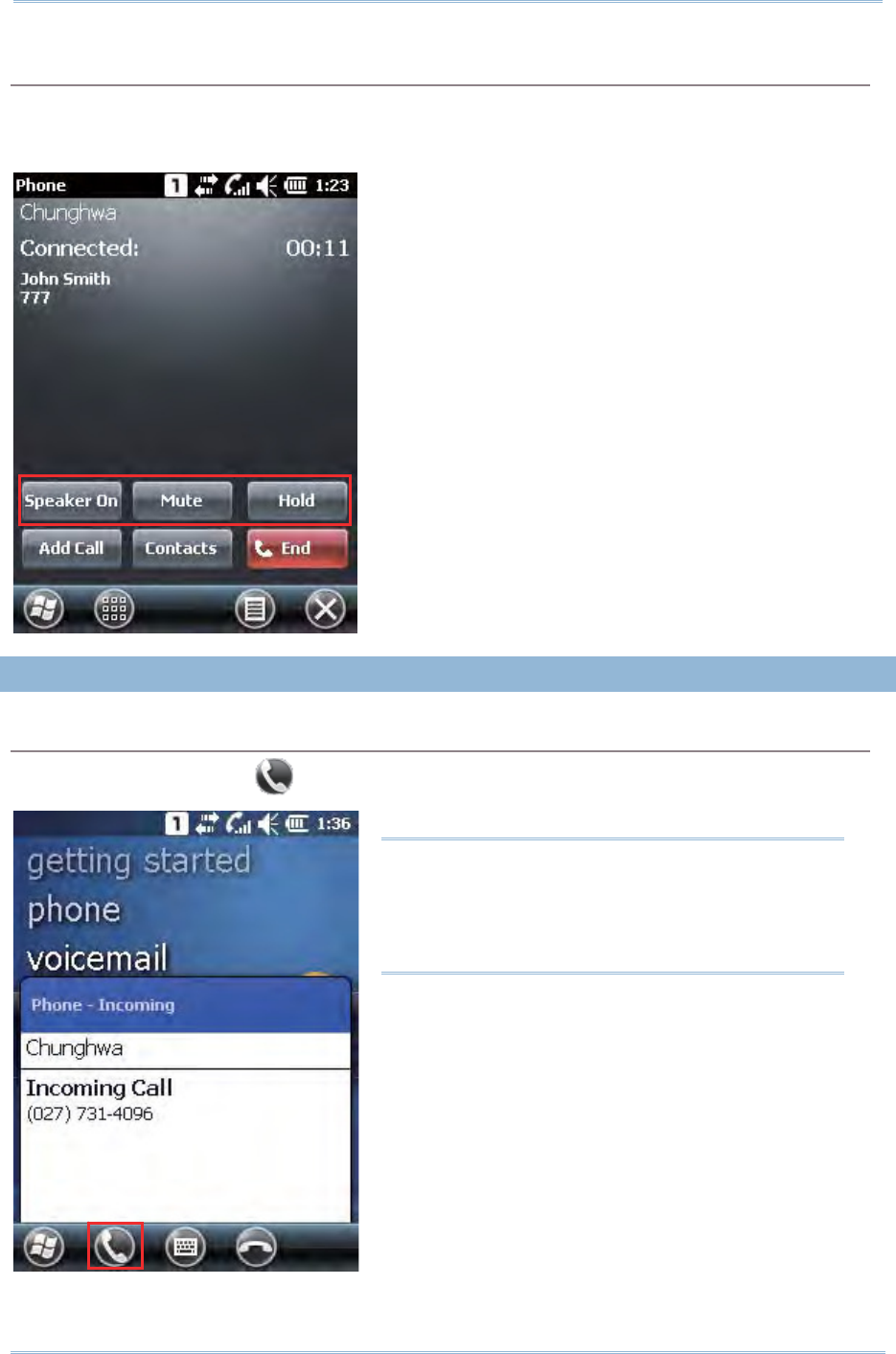
124
9200 Mobile Comput e
r
Ref erence Manual
During a Call
During a call, you m ay select to turn on t he speaker, m ute the receiver, or hold t he line
by tapping the respect ive on- screen buttons. Alternatively you m ay place another call
by the Add Ca ll button, or open t he Co nt a ct s application.
6.4. 3. ANSWER A CALL
Answering a Call
Tap the Answ er button or press [ SEND] from the physical keypad.
Note: I f your wired headset (CTI A standard)
has an int egrat ed hook switch, press the hook
swit ch during an incom ing call t o answer it .
When finished with the phone conversation,
press the hook swit ch again to end t he call.
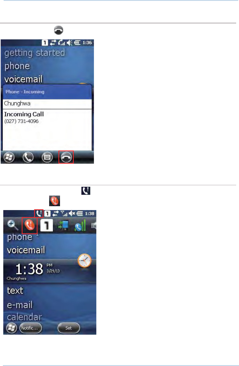
125
Chapt er 6 Using t he Phone
Ignoring a Call
Tap I gnore button or press [ END] from the physical keypad.
Viewing a Missing Call
When you have a m issed call, will be displayed on t he t it le bar. Tapping it will reveal
a m issed call icon . Tap it t o open the Call History page t o identify the m issed call.
OR
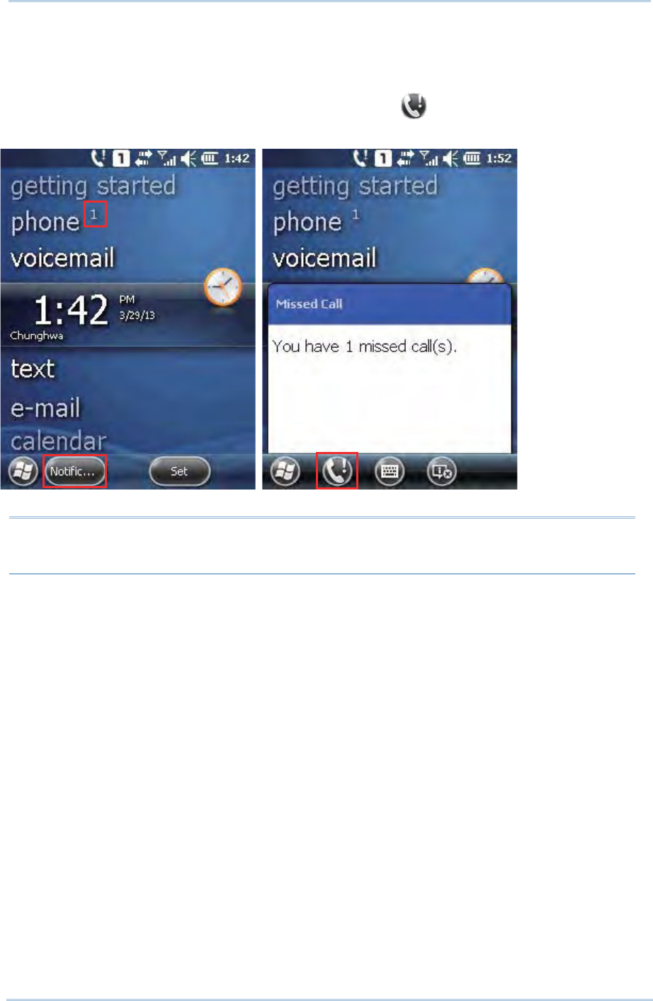
126
9200 Mobile Comput e
r
Ref erence Manual
On the Today Screen, an uppercase num ber “ 1” will appear next to the “ Phone” label t o
indicate you have 1 m issed call. Tap N ot if ica t ion on the soft key bar to view t he
not ificat ion m essage.
When the not ificat ion m essage pops- up, tapping t he icon on the softkey bar will
open the Call History page, where you can check inform ation about the m issed call.
Note: The right LED on top of t he m obile com puter will also flash red to notify there is
a m issed call.
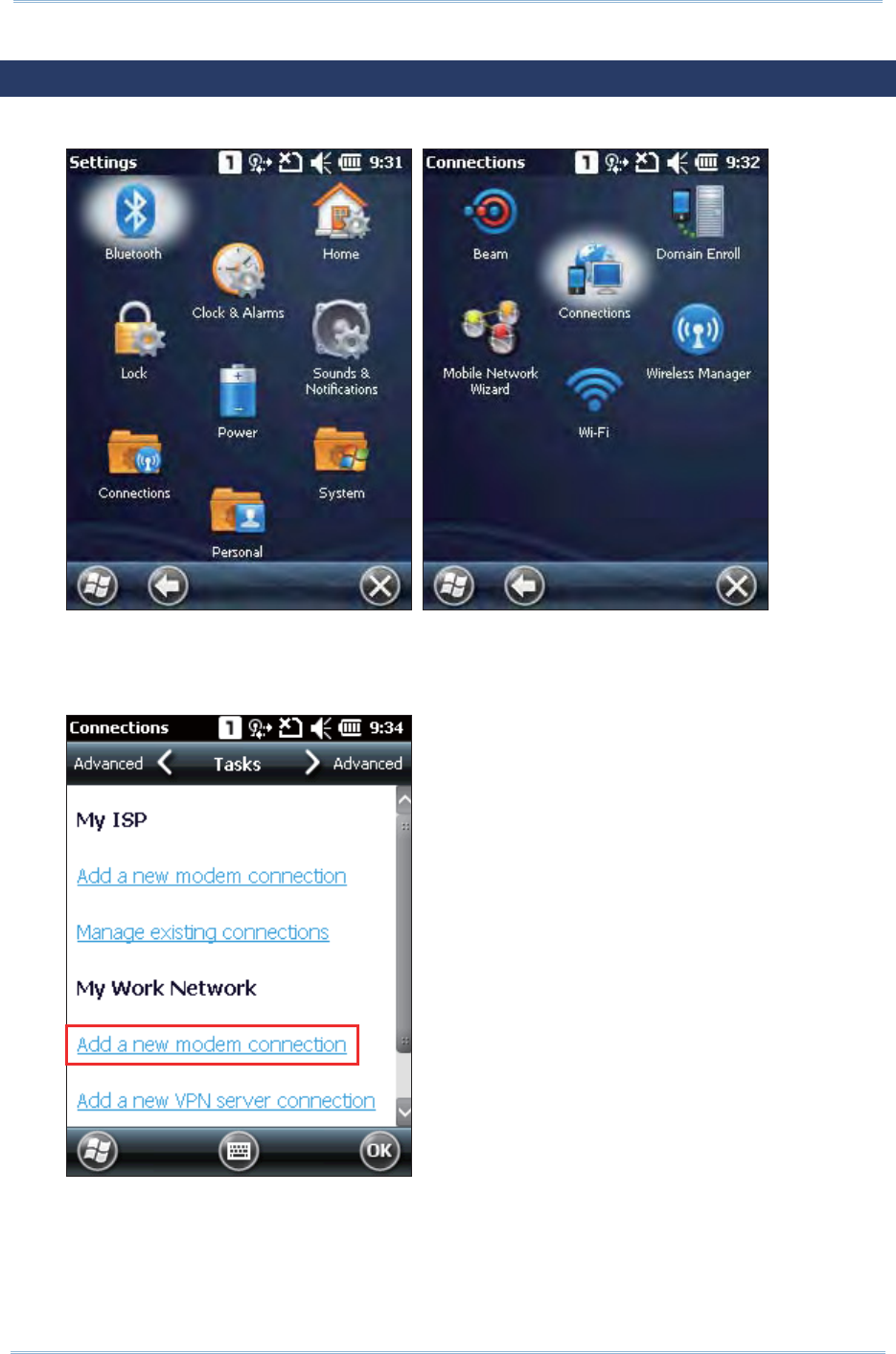
127
Chapt er 6 Using t he Phone
6.5. CONFIGURING GPRS NETWORK
1 . Tap Sta r t Scr een | Settings | Connect ions and select Connect ions.
2 . I nitially, you have to configure the GPRS settings.
Tap Add a new m ode m conne ct ion and follow the on- screen instruct ions to
enter the connection nam e and m odem t ypes.
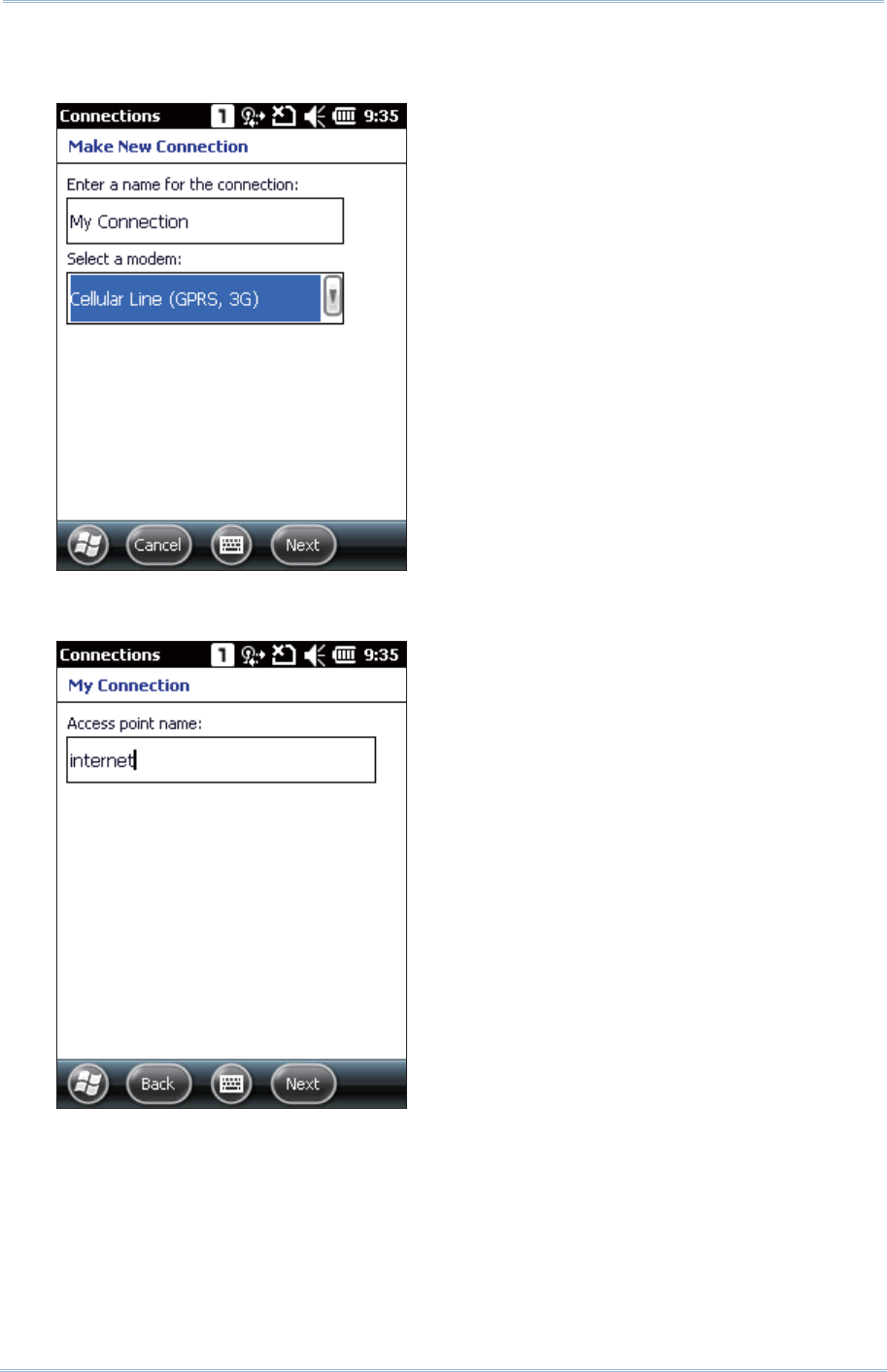
128
9200 Mobile Comput e
r
Ref erence Manual
3 . Ent er t he connect ion nam e and select “ Cellular Line ( GPRS, 3G)” from the
drop-down list . Tap N e x t .
4 . Specify the GPRS AP nam e for t he m obile com puter to connect to, for exam ple,
“ int ernet ” . Tap N e x t .
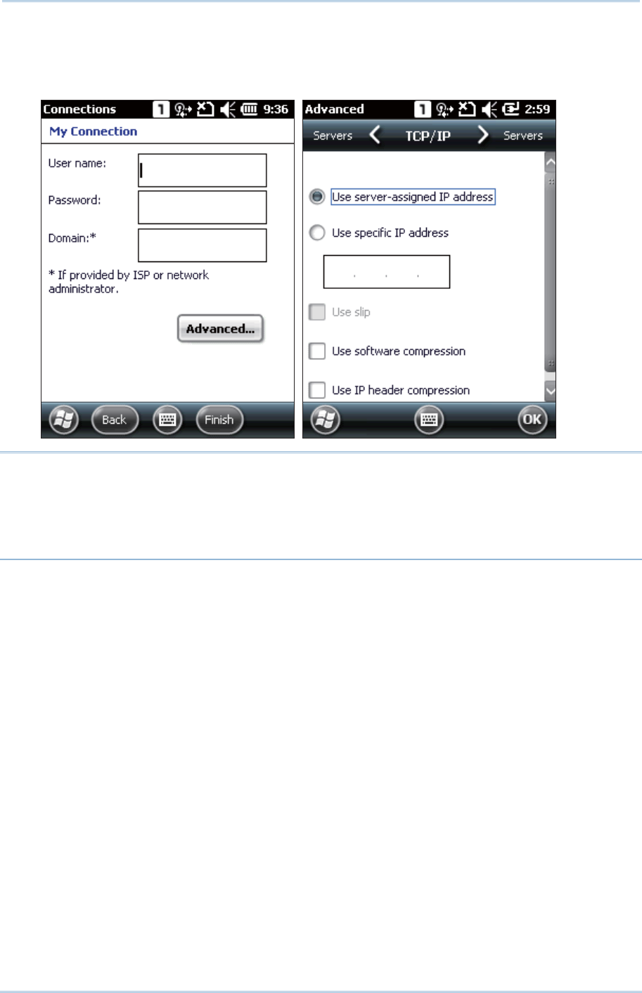
129
Chapt er 6 Using t he Phone
5 . Ent er user nam e, password and dom ain inform at ion as necessary. Tap Adva nce d
to access TCP/ I P and server settings.
When all settings are com plet ed, tap Finish.
Note:
( 1) You m ust connect to the GPRS m odem specified by the m obile phone operator.
( 2) Perform ing hardware reset will not affect the wireless connect ion set tings m ade
under Wireless Manager. On the next system start up, the m obile com puter will
reflect the sam e wireless connect ion st atuses as previously set .

130
9200 Mobile Comput e
r
Ref erence Manual

131
The Rea de r Configurat ion u t ility allows you to m anage t he barcode reader integrated
on the m obile com puter.
IN THIS CHAPTER
7.1ʳLaunch Reader Configuration ...................................... 132
7.2ʳConfigure Reader Settings..........................................133
USING READER CONFIGURATION UTILITY
Chapter 7
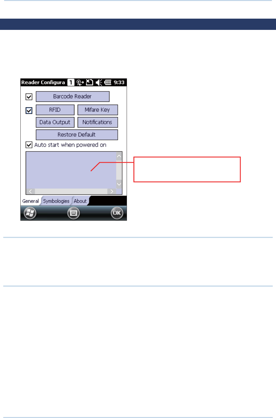
132
9200 Mobile Comput e
r
Ref erence Manual
7.1. LAUNCH READER CONFIGURATION
1 . Tap Star t Scre en | Se t t in gs | System | Rea de r Configur ation to open the
Reader Configurat ion Utility.
2 . Configure the associated reader set t ings and barcode set t ings on Ge ner a l tabbed
page according t o your needs. Perform a test scan and view t he barcode and
decoded data in t he content field.
Note:
( 1) The Reader Configurat ion utilit y autom at ically det ect s t he scan engine inst alled on
the m obile com puter.
( 2) I f you wish t o rest ore the reader to default settings, delete the ReaderCfgI NI .t xt file
in the Flash st orage before enabling t he program . Alternatively, tap t he Restore
D ef au lt butt on on t he reader settings page.
Scanned data will display in the
content field
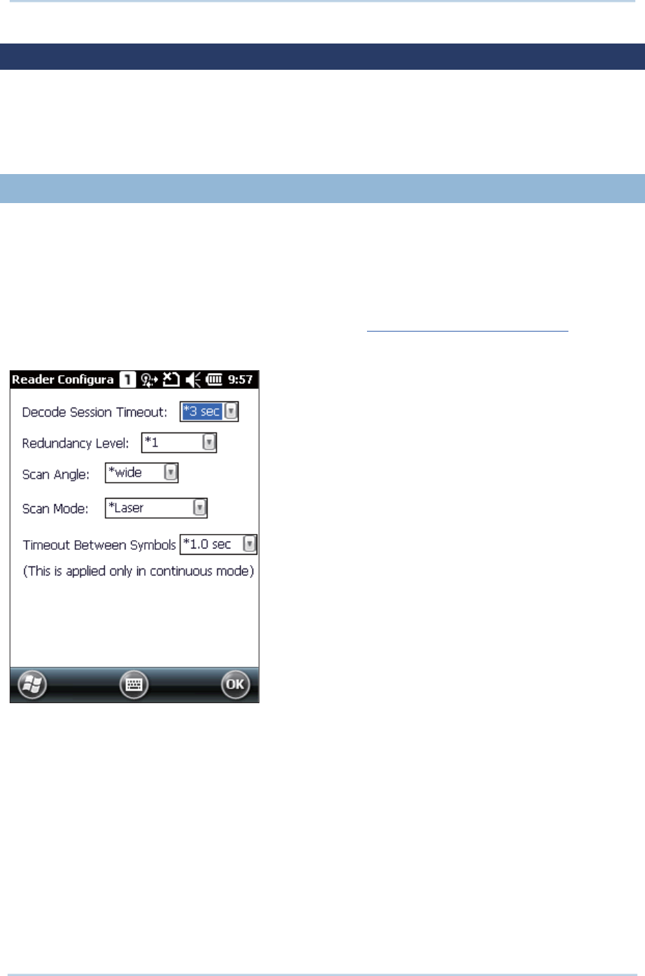
133
Chapt er 7 Using Reader Configurat ion Ut ilit y
7.2. CONFIGURE READER SETTINGS
The m obile com puter is capable of reading printed barcodes. The reader m odules can be
eit her a CCD reader, laser ( 1D) reader, or 2D im ager. The m obile com puter is inst alled
wit h Re ader Configur ation t o set the scan engine built wit hin. Use Reader
Configuration t o creat e a profile of set tings t hat best suit your needs.
7.2. 1. BARCODE READER
Barcode reader configurations depend on the scan engine( s) inst alled on t he m obile
com puter. Configure t im eout , redundancy level and scanning behaviours according to
your needs.
To access barcode reader set t ings:
1 . Open Rea de r Configurat ion as described in Launch Reader Configuration.
2 . Tap Barcode Reader on General t abbed page.

134
9200 Mobile Comput e
r
Ref erence Manual
CCD READER SETTINGS
Barcode Reader Description
CCD Reader Tap the Bar code Re ade r butt on to configure reader sett ings for t he
CCD scan engine.
Refer to the Reader Sett ings Table in Appendix I I - CCD (SM1).
Decode Session Timeout Set s t he m axim um t im e (configurable from 1 to 9 sec) for t he
decoding process during a scan att em pt . The default value is 3 sec.
Redundancy Level Set s how m any successful readings should be done before linear
barcodes such as Codabar, MSI , and I nterleav ed 2 of 5 can be
decoded. Levels 1 to 4 available.
The readings needed for each level are as follows:
Level 1 The following barcodes m ust be successfully r ead
tw ice before being decoded: Codavar , MSI , I ndust rial
25 ( Discret e 25) , I nt erleaved 25.
Level 2 All barcodes m ust be successfully read tw ice before
being decoded.
Level 3 All barcodes m ust be successfully read tw ice before
being decoded, except for the following w hich m ust be
read t hree t im es: MSI , I ndust rial 25 (Discrete 25),
I nterleaved 25.
Level 4 All barcodes m ust be successfully read t hree tim es
before being decoded.
Scan Mode Set s the reader’s scanning behavior. Default is “ Laser” .
“ Cont inuous” to decode t he sam e barcode repeatedly or decode
different bar codes in a continuous m ot ion.
“ Laser” for scanning by pressing t he scan trigger.
Tim eout Between Sym bols Only available for Cont inuous m ode. The default value is 1 sec.
1D LASER READER SETTINGS
Barcode Reader Description
Laser Reader Tap t he Ba rcode Rea der but ton t o configure reader set tings for t he
laser scan engine.
Refer to the Reader Sett ings Table in Appendix I I I -ʳLaser ( SE955) .
Decode Session Timeout Set s t he m axim um t im e (configurable from 1 to 9 sec) for t he
decoding process during a scan att em pt . The default value is 3 sec.

135
Chapt er 7 Using Reader Configurat ion Ut ilit y
Redundancy Level Set s how m any successful readings should be done before linear
barcodes such as Codabar, MSI , and I nterleav ed 2 of 5 can be
decoded. Levels 1 to 4 available.
The readings needed for each level are as follows:
Level 1 The following barcodes m ust be successfully r ead
tw ice before being decoded: Codavar , MSI , I ndust rial
25 ( Discret e 25) , I nt erleaved 25.
Level 2 All barcodes m ust be successfully read tw ice before
being decoded.
Level 3 All barcodes m ust be successfully read tw ice before
being decoded, except for the following w hich m ust be
read t hree t im es: MSI , I ndust rial 25 (Discrete 25),
I nterleaved 25.
Level 4 All barcodes m ust be successfully read t hree tim es
before being decoded.
Scan Angle Select the scan angle for Long Range Laser scan engine. Default is
“ wide” .
“ wide” for 35°
“ narrow” for 47°
Scan Mode Set s the reader’s scanning behavior. Default is “ Laser” .
“ Cont inuous” to decode t he sam e barcode repeatedly or decode
different bar codes in a continuous m ot ion.
“ Laser” for scanning by pressing t he scan trigger.
Tim eout Between Sym bols Only available for Cont inuous m ode. The default value is 1 sec.
2D IMAGER SETTINGS
Barcode Reader Description
2D Reader The 2D scan engine is capable of reading linear and 2D barcodes.
Tap t he Barcode Rea der but ton t o configure reader set tings for t he
2D scan engine.
Refer to the Reader Sett ings Table in Appendix I V - ʳ2D I m ager
( SE45 00 DL) .
Decode Session Timeout Set s t he m axim um t im e (configurable from 1 to 9 sec) for t he
decoding process during a scan att em pt . The default value is 3 sec.
Decode I llum inat ion Decide w het her t o flash illum inat ion on every bar code capture to aid
decoding.
Turn on (internal LED)
Turn off
Aiming Pat t er n Decide whet her t o project t he aim ing pat tern during barcode capture.
Turn on
Turn off

136
9200 Mobile Comput e
r
Ref erence Manual
Redundancy Level Set s how m any successful readings should be done before certain
barcodes are decoded. Levels 1 to 4 available; default sett ing is Level
1. The readings needed for each level are as follows:
Level 1 The following barcodes m ust be successfully r ead
tw ice before being decoded:
Barcode Types Code Length
Codabar 8 charact ers or less
MSI 4 charact ers or less
I ndustrial 25 (Discrete 25) 8 char act ers or less
I nterleaved 25 8 charact ers or less
Level 2 All barcodes m ust be successfully read tw ice before
being decoded.
Level 3 All barcodes m ust be successfully read tw ice before
being decoded, except for the following w hich m ust be
read t hree t im es:
Barcode Types Code Length
Codabar 8 charact ers or less
MSI 4 charact ers or less
I ndustrial 25 (Discrete 25) 8 char act ers or less
I nterleaved 25 8 charact ers or less
Level 4 All barcodes m ust be successfully read t hree tim es
before being decoded.
Security Level Selects the securit y level to ensure decoding accuracy considering the
printed qualit y of certain barcodes. Default set t ing is Level 0. The
higher the level, the great er the security. Opt ions are:
Level Description
0 With this default, the scan engine is aggressive enough to
decode m ost “ in- spec” barcodes.
1 Select t his level if m isdecodes have occurred. I t fixes
m ost m isdecodes.
2 Select t his level if Level ˄ should fail to elim inat e
m isdecodes.
3 Select t his level if Securit y Level 2 should fail t o prevent
m isdecodes. However, as this level act ually im pair s the
decoding abilit y of t he decoder, a safer solut ion would be
to im prove t he qualit y of the bar codes t o read.
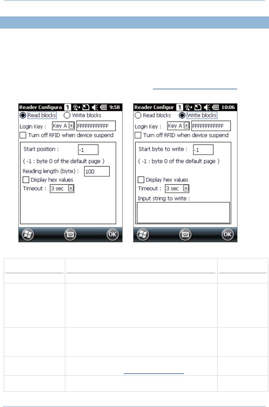
137
Chapt er 7 Using Reader Configurat ion Ut ilit y
7.2. 2. RFID READER
When an RFI D reader is detect ed, the RFI D Reader opt ion is available on Gener a l t ab
of the reader settings page. The RFI D Reader check box is selected by default . Deselect
it to disable the RFI D reader on t he m obile com puter. This is occasionally needed when
you only want to read printed barcodes, lest RFID tags are read and decoded.
To access RFI D reader set t ings:
1 . Open Rea de r Configurat ion as described in Launch Reader Configuration.
2 . Tap RFI D on Gene ral tabbed page.
READ BLOCKS SETTINGS
Setting Descriptions Default
Read blocks Reads data from an RFI D tag. Selected
Login Key Shows what key A and key B current ly is.
Keys A and B are what the RFI D reader m odule
relies on t o access ( read or w rit e) an RFI D t ag. I n
default st ate, both keys are a sequence of t welve
“ F” charact ers because t hey are Mifare tag’s fact ory
default . Modify these default keys if necessary.
Key A &
FFFFFFFFFFFF
Turn off RFI D when
device suspend
Select t his to t urn off RFI D function when t he m obile
com puter ent ers suspension. Once t he m obile
com puter is resum ed from suspension, RFI D function
will be aut om at ically restored.
Deselect ed
St art position Defines where t o st art reading data from .
See Appendix V: RFI D Tag Default Block.
- 1 ( default
block, byte 0)
Reading length
( byt e)
Defines how m any bytes of dat a to read. 100

138
9200 Mobile Comput e
r
Ref erence Manual
Display hex values Displays decoded dat a in hex values.
Generally t he readable RFI D dat a lies in a user
block. I f the data t o collect is located in a non-user
block such as t he lock block, select Display he x
values in case t he dat a t o collect involves any
invisible character.
Deselect ed
Tim eout Set s the m aximum t im e for decoding an RFI D Tag
during a scan att em pt. Configurable from 1- 20 sec.
3 sec
WRITE BLOCKS SETTINGS
Setting Descriptions Default
Writ e blocks Writ es data to an RFI D tag Deselect ed
Login Key Shows what key A and key B current ly is.
Keys A and B are what the RFI D reader m odule
relies on t o access ( read or w rit e) an RFI D t ag. I n
default st ate, both keys are a sequence of t welve
“ F” charact ers because t hey are Mifare tag’s
fact ory default. Modify t hese default keys if
necessary.
Key A &
FFFFFFFFFFFF
Turn off RFI D when
device suspend
Select t his to t urn off RFI D funct ion when device ent ers
suspension. Once t he m obile com put er is resum ed
from suspension, RFI D funct ion will be autom atically
rest ored.
Deselect ed
St art byte t o writ e Defines where to st art writ ing data t o.
See Appendix V: RFI D Tag Default Block.
- 1 ( default block,
byt e 0)
Display hex values Writ es data in hex values.
Generally an RFI D tag’s writ eable block lies in the
user block. However, if the block to writ e is a
non-user block such as the lock block, select Use
hex values to write dat a in hex values in case t he
block to w rite involves any invisible character.
Deselect ed
Tim eout Set s the m axim um t im e (configurable from 1 t o 20
sec) for the decoding process during a scan att em pt .
3 sec
I nput str ing to write Defines what to write.
Note that different RFI D tags m ay have different
default blocks ( also “pages” ), and different am ount
of byt es and num ber of blocks. The dat a writ ten
m ight be truncated t o fit the blocks of the targeted
RFI D tag. Therefore part of the dat a m ay be
discarded when it com es t o the end of a block end.
See Appendix V: RFI D Tag Default Block.
- -
Note: Refer to t he specificat ions of the RFI D t ag to read for it s m em ory organizat ion.
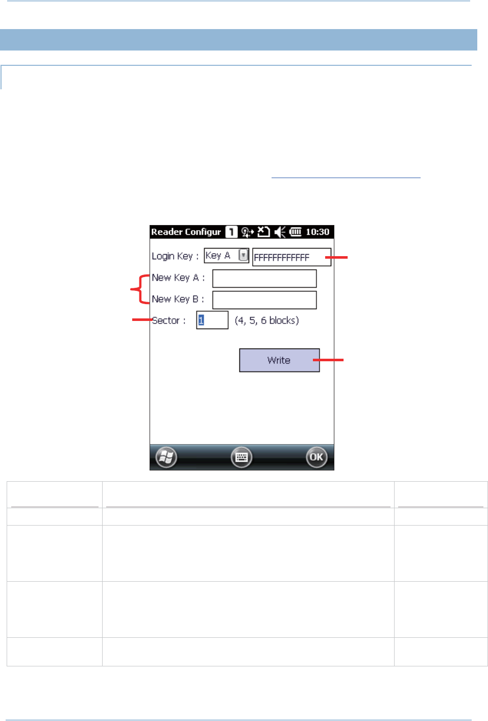
139
Chapt er 7 Using Reader Configurat ion Ut ilit y
7.2. 3. MIFARE KEY
MIFARE KEYS
Mifar e Keys set t ing changes t he security keys A and/ or B for a Mifare tag’s dat a block.
Keys A and B are two keys t hat enable the RFI D reader t o access (read or writ e) a Mifare
tag’s data block.
To open Mifa r e Keys setting page:
1 . Open Rea de r Configurat ion as described in Launch Reader Configuration.
2 . Tap Mifa r e Keys on Gener a l t abbed page.
Settings Descriptions Default
Login Key Select bet ween key A and key B for t he login key. Key A
New Key A Assigns new key A, which m ust be a hex string of 12 bytes.
I f it is the other key (key B) that you want to change,
you still need to assign t he curr ent key A here to be
able t o enact t he change.
- -
New Key B Assigns new key B, which m ust be a hex st ring of 12 byt es.
I f it is t he ot her key ( key A) t hat you want to change,
you still need to assign t he curr ent key B here to be
able t o enact t he change.
- -
Sector Set s the blocks to apply t he change. 1
( blocks 4, 5, & 6)
Shows what each key A
and B currently is.
Edit s keys A & B
Assigns the blocks to
apply t he change
Tap t his but ton t o enact the
change.

140
9200 Mobile Comput e
r
Ref erence Manual
To change t he value of key A and/ or B:
1 . Open Rea de r Configurat ion as described in Launch Reader Configuration
2 . Tap Mifa r e Keys on General t abbed page.
3 . Configure which key t o change, how it is changed t o, and the block t o apply t he
change.
4 . Tap (slight ly cont act) the m obile com puter’s scanning window wit h the RFI D tag to
write the change to.
5 . Tap the W r it e but t on on M ifare Keys settings page. The change is writ t en to t he
RFI D t ag.
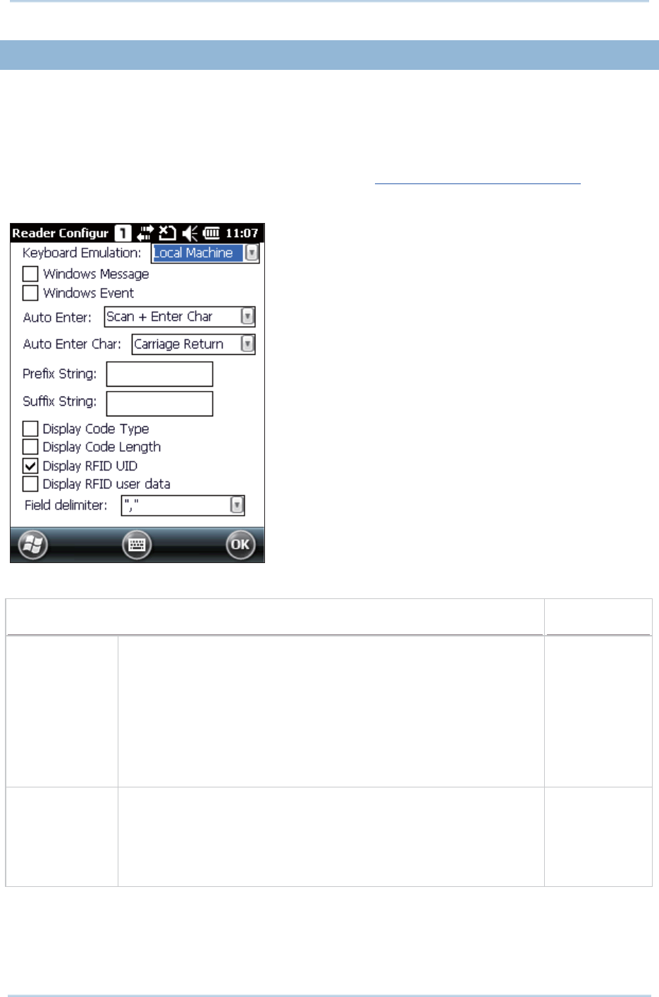
141
Chapt er 7 Using Reader Configurat ion Ut ilit y
7.2. 4. DATA OUTPUT
Tap the Data Out pu t but t on on t he Ge ne r al t abbed page to access settings for data
out put aft er decoding as well as configure the associat ed set t ings.
To access data out put set t ings:
1 . Open Rea de r Configurat ion as described in Launch Reader Configuration.
2 . Tap Da t a Output on Gene r a l tabbed page.
WHERE TO OUTPUT
Data Output Default
Keyboard
Em ulat ion
Dat a is em ulated as typed text and sent t o the act ive window.
When “ Local m achine” is selected, sim ply run your
applicat ion or built - in program , such as WordPad, t o st art
wit h data collection.
When “ RDP server” is select ed, run t he Rem ot e Desktop
Connect ion program t o connect t o a rem ot e com put er.
Note that t his opt ion is unable to em ulate double- byte font ,
such as Big-5 or Unicode charact ers on t he rem ot e PC.
Local Machine
Windows
Message
When select ed, a Windows m essage will be broadcast ed aft er
decoding.
I ntercept the decode m essage in your application.
Call Windows API (ReadMsgQueue) in your application t o
retrieve the decoded data.
Disable

142
9200 Mobile Comput e
r
Ref erence Manual
Windows Event When select ed, a Windows event will be broadcast ed after
decoding.
I ntercept the decode event in your applicat ion.
Call Windows API (ReadMsgQueue) in your application t o
retrieve the decoded data.
Disable
Note:
( 1) Refer to 9200 .NET or C/ C+ + Program m ing Guide for det ails on Windows Message
and Windows Event. Sam ple program s are provided by request .
( 2) For the use with a barcode decoding program ot her t han ReaderConfig.exe, a
dynam ic- link library ( DLL) file is provided.
HOW TO OUTPUT
Aut o Ent er Adds an Ent er character before or after each scanning act . This
funct ion spares you the trouble of pressing [ Ent er] key to confirm
each scan. Options are:
None
Scan + Ent er Char
Ent er Char+ Scan
Scan + Ent er
Char
Aut o Ent er
Char
Adds a key code before or after the decoded data. This set t ing is
available only when “ Aut o Ent er” is enabled. Opt ions ar e:
None
Carriage ret urn
Tab
Space
Com m a
Sem icolon
Carriage
Ret urn
Prefix String Affixes 0~ 10 characters t o t he left of the out put dat a. NULL
Suffix String Affixed 0~ 10 charact ers t o the right of t he out put data. NULL
Display Code
Type
Prefixes code type t o the decoded data. Disabled
Display Code
Lengt h
Suffixes code lengt h t o the decoded dat a. Disabled
Display RFI D
UI D
Outputs t he UI D of t he RFI D tag t o read.
This set ting is available only when an RFI D reader is
integrated on the m obile com put er and is enabled.
Enabled
Display RFI D
user dat a
Outputs t he user dat a of t he RFI D tag to read.
This set ting is available only when an RFI D reader is
integrated on the m obile com put er and is enabled.
Disabled
Field delim it er Adds a field delim it er in t he decoded data to separate t he dat a to
segm ents.
For printed barcodes: This delim iter separat es code type ,
decoded dat a, and code lengt h ( if applicable)
For RFI D tags: This delim iter separat es UI D and user data ( if
both are applicable)
“ ,” ( com m a)
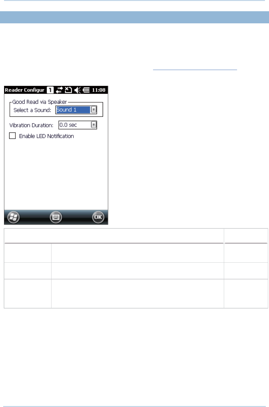
143
Chapt er 7 Using Reader Configurat ion Ut ilit y
7.2. 5. NOTIFICATIONS
The N ot if ica t ion s page allows you to configure how you want t o be notified of a
successful decoding.
To access not ificat ion set t ings:
1 . Open Rea de r Configurat ion as described in Launch Reader Configuration.
2 . Tap Notificat ions on General t abbed page.
Sound / Vibration Default
Good Read via
Speaker
Set s the sound for good read.
Select bet ween Mut e and sounds 1 t hr ough 9.
Sound 1
Vibration
Duration
Set s whether to enables tactile feedback (vibrat ion) for good
read, and vibrat ion durat ion. Configurable bet ween 0~ 5.0 (sec.)
0 ( = Disable)
Enable LED
Notificat ion
Select t he check box t o enable Scanner beam LED and Scanner
decode ( Good Read) LED. The t op right LED will light up in
orange when t he scan key is pressed. The top left LED will flash
green to indicat e a successful decoding.
Disable
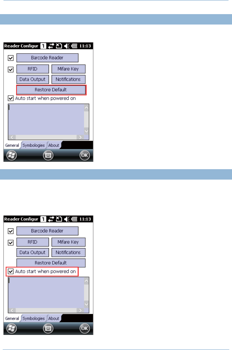
144
9200 Mobile Comput e
r
Ref erence Manual
7.2. 6. RESET TO DEFAULT
Tap Re st ore Defa ult on t he reader set tings page t o reset all sett ings back to default.
7.2. 7. AUTO-START READER CONFIGURATION
I f you would like to auto- st art t he Re ader Configu rat ion applicat ion next t im e the
m obile com puter is powered on, select t he “Aut o start when powered on” check box.
Re ader Configura t ion will run in t he background once the m obile com puter is rest arted
to facilit ate barcode reading.
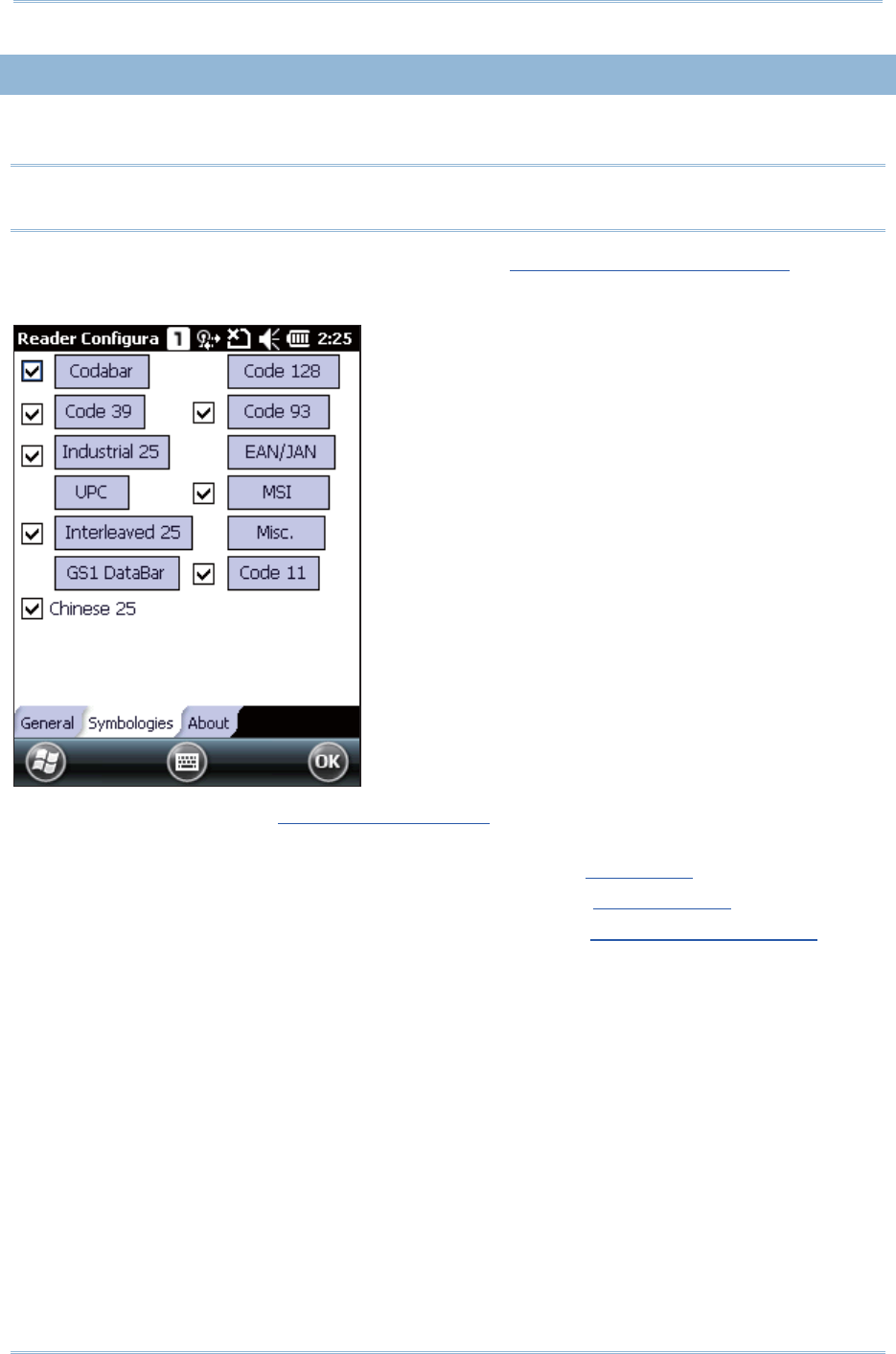
145
Chapt er 7 Using Reader Configurat ion Ut ilit y
7.2. 8. SYMBOLOGY SETTINGS
On the Sym bologies tab, det erm ine whet her to enable or disable a specific sym bology.
Note: The sym bology set t ings vary by the scan engine ( CCD, 1D laser or 2D im ager)
installed.
1 . Open Rea de r Configurat ion as described in Launch Reader Configuration.
2 . Tap Sym bologie s tabbed page.
Refer to Appendix I - Scan Engine Set t ings for t he sym bologies support ed by the
installed scan engine.
Refer to the Sym bology Set t ings Table in Appendix I I - CCD ( SM1).
Refer to the Sym bology Set t ings Table in Appendix I I I - Laser ( SE955) .
Refer to the Sym bology Set t ings Table in Appendix I V - 2D I m ager ( SE4500DL).
146
9200 Mobile Comput e
r
Ref erence Manual
7.2. 9. ABOUT
This tabbed page delivers t he soft ware version, developer info, and copyright
inform at ion.
1 . Open Rea de r Configurat ion as described in Launch Reader Configuration.
2 . Tap About t abbed page.

147
The Cam era utility allows taking st ill im ages or videos from the built - in digit al cam era.
Tap Sta r t Scr een | Cam e ra to open the Cam era ut ilit y.
IN THIS CHAPTER
8.1ʳCam era I nt erface...................................................... 148
8.2ʳTaking a Picture ........................................................ 149
8.3ʳShooting a Video....................................................... 151
8.4ʳCam era Settings ....................................................... 153
8.5ʳPict ures & Videos ...................................................... 155
USING CAMERA
Chapter 8
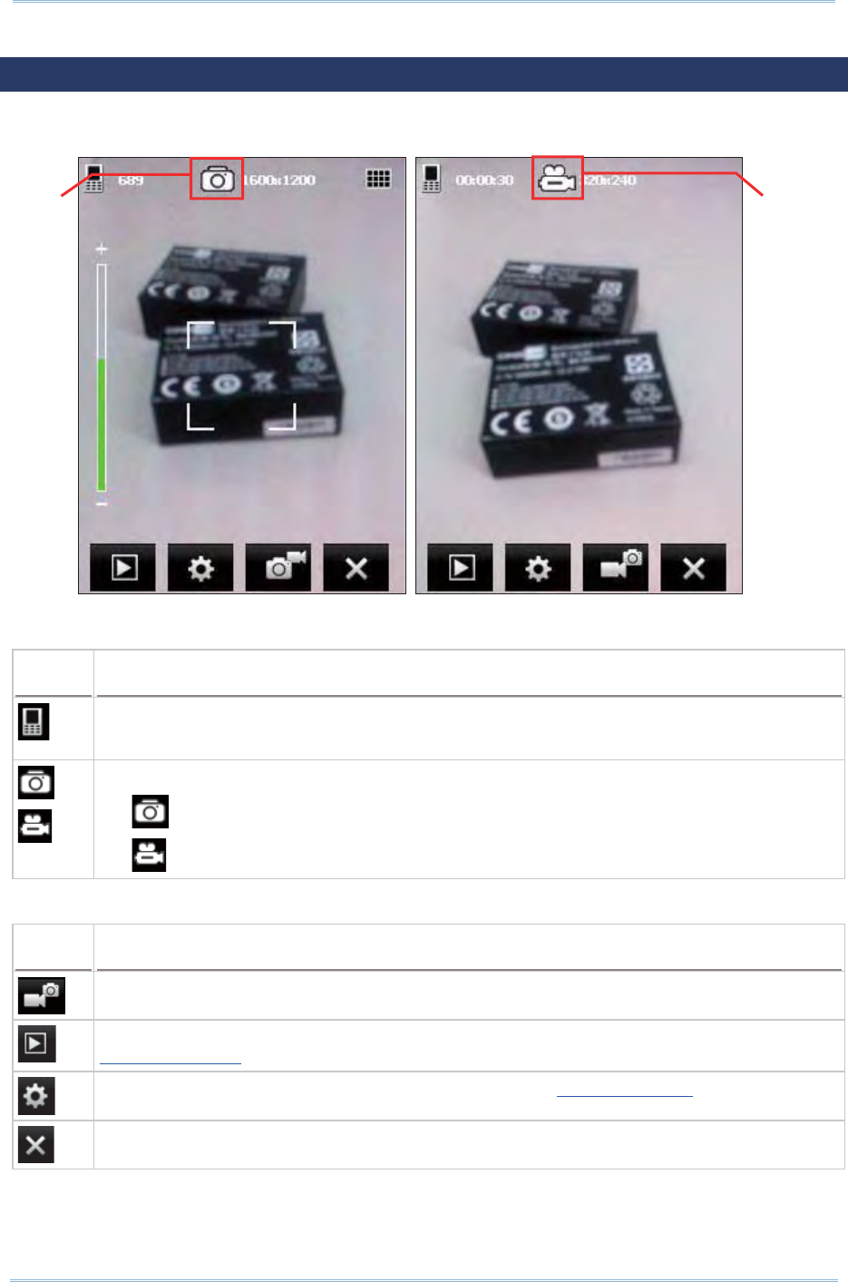
148
9200 Mobile Comput e
r
Ref erence Manual
8.1. CAMERA INTERFACE
The Cam era applicat ion supports still im age capt uring and video recording.
The icons on t op of the screen indicat e cam era stat us and im age properties.
Icon Description
I n Still m ode: num ber of pictures t hat can be t aken.
I n Video m ode: available recording t im e.
Cam era status and inform ation on im age resolution.
indicates t he camera is in Still m ode
indicates the cam era is in Video m ode
The but t ons at the bot t om of the screen are described as below.
Button Description
Tap t o switch between Still and Video m odes.
Tap t o open Pict ur es & Videos folder t o view im ages and playback videos. Refer to
Pict ures & Videos.
Tap t o configure cam era set tings if necessary. Refer t o Cam era Sett ings.
Exit and turn off the cam era.
Video m ode
St ill m ode
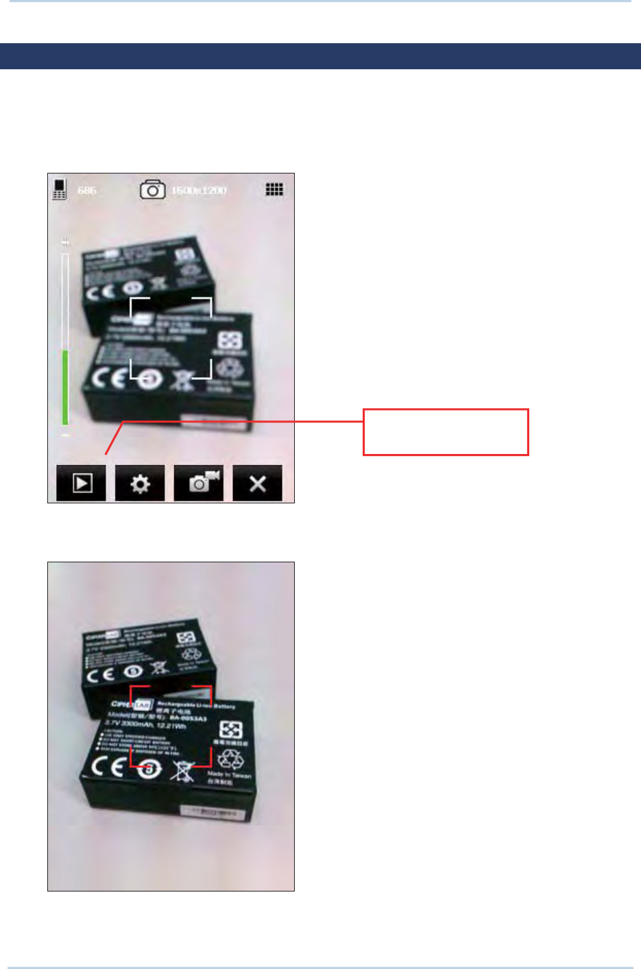
149
Chapt er 8 Using Camera
8.2. TAKING A PICTURE
When launched, t he cam era is set to St ill m ode by default for pict ure taking, and a
preview screen is displayed.
1 . Aim at the obj ect you want to shoot. Drag the slider t o zoom in ( + ) or zoom out
( - ) an im age.
2 . Press [ Scan] key or [ Ent er] on t he physical keypad t o t ake a picture.
Each pict ure will be aut om at ically saved under the designated storage locat ion.
Drag t he slider to
adjust the focus
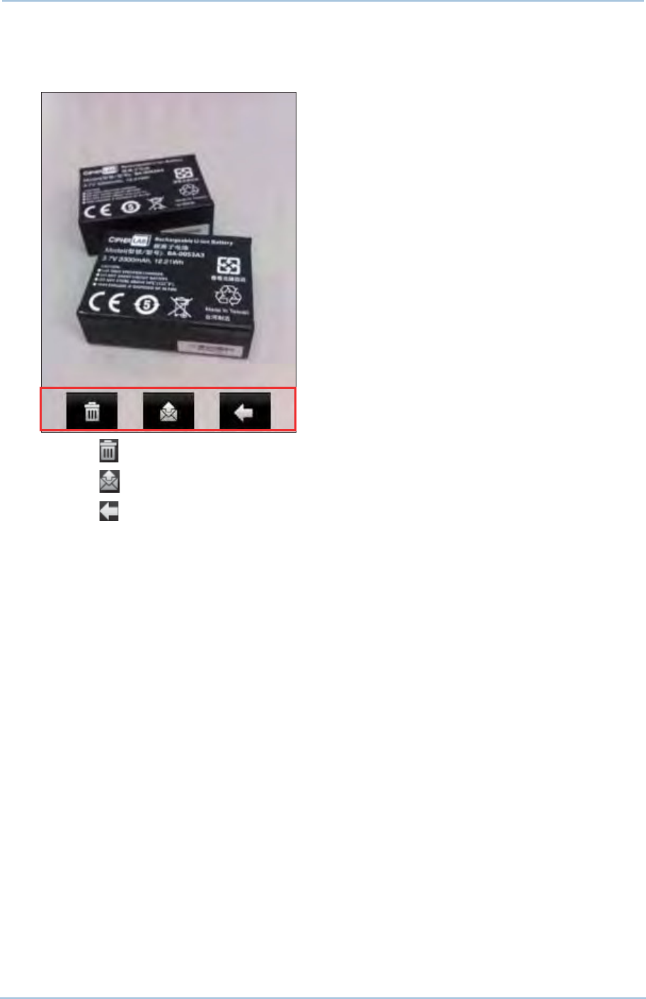
150
9200 Mobile Comput e
r
Ref erence Manual
3 . Before the cam era ut ilit y j um ps back to the preview screen, you m ay tap t he
advanced but tons at the bot t om of the review screen, which will be ret ained for
about five seconds.
Tap t o delet e t he im age file.
Tap to send the picture via t ext m essage or e- m ail.
Tap t o return to the preview screen.
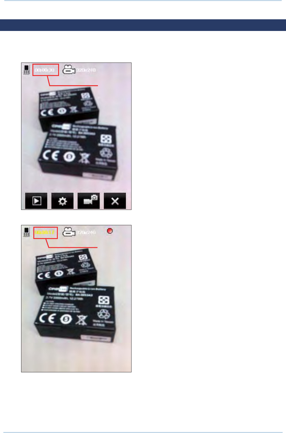
151
Chapt er 8 Using Camera
8.3. SHOOTING A VIDEO
When sw it ching to Video m ode, a preview screen will be displayed.
1 . Hold st ill and take aim at the obj ect you want to shoot
2 . Press [ Scan] or [ Ent er] on the physical keypad to start recording a video.
Available recording time
Remaining recording time
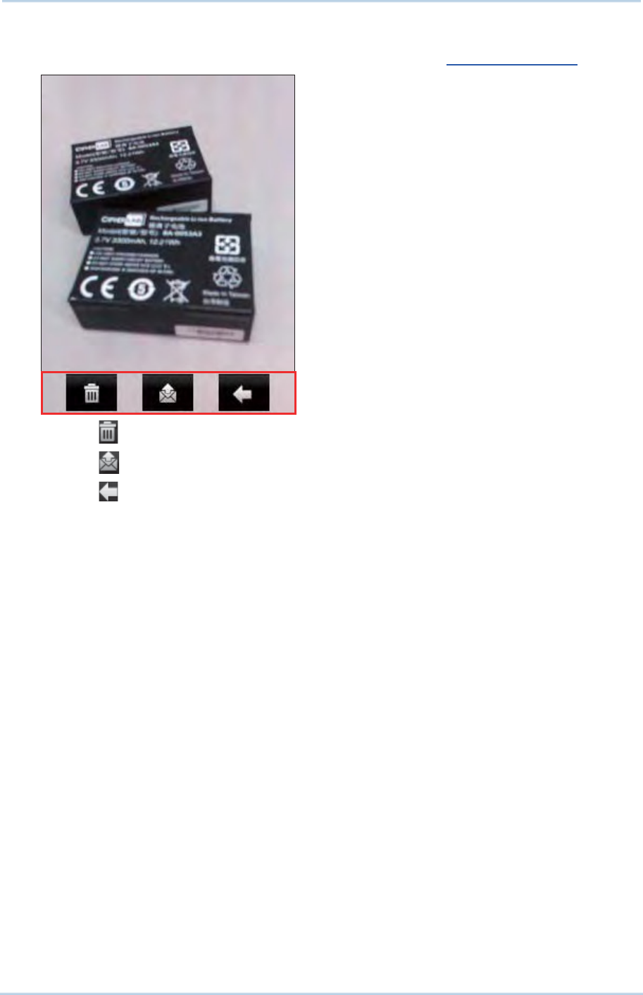
152
9200 Mobile Comput e
r
Ref erence Manual
3 . Press [ Scan] or [ Ent er] on t he physical keypad t o end recording. Ot herwise, it will
st op aut om at ically after reaching the t im e lim it. Refer to Advanced Settings.
Tap t o delet e t he im age file.
Tap to send the picture via t ext m essage or e- m ail.
Tap t o return to the preview screen.
153
Chapt er 8 Using Camera
8.4. CAMERA SETTINGS
On the soft key bar, tap t he but t on t o configure cam era set t ings if necessary.
Brightness, Contrast, Sharpness
Adj ust s brightness, contrast, and sharpness for t he pict ure t o t ake.
Mode
Set s a scene m ode for t he pict ure t o t ake. By default , no special m ode is applied.
Options are:
Icon Description
Backlight
Night m ode
St abilize
Out door
Low light
White Balance
Tap to select a specific scenario for setting white balance. By default , t he cam era is
set t o adj ust aut om at ically. Options are:
Icon Description
Bright light
I ndoor light
Sunny light
Cloudy light
Effect
Applies a special effect t o t he picture to take. By default , no special effect is applied.
Options are:
Monochrom e, Negative, and Sepia
Timer
Enables the t im er which allows t aking t he pict ure a period of t im e aft er t he [ Scan]
key or [ Ent er] is pressed. By default , t im er is disabled. Options are:
3 seconds, 5 seconds, and 10 seconds
This is only applicable in Still m ode.
154
9200 Mobile Comput e
r
Ref erence Manual
GPS tagging
Enables/ disables GPS tagging for the pict ure t o t ake. Options are:
Enable, Disable
Quality
Set s quality for t he pict ure t o t ake. Options are:
High, Medium
Size
Select the im age size for t he pict ure t o t ake. Opt ions are:
320x240, 640x480, 1280x960, 1600x1200, 2048x1536
Storage
By default, t he capt ured pict ures are stored on the m obile com puter’s m ain
m em ory.
Camera
Mode Store Folder File Format
St ill Mode \ My Device\ My Docum ent s
\ My Pict ures\ YYMMDD
im gXXXXX.j pg ( “ XXXXX” stands for
5- digit serial num ber start ing from
“00000”)
Video Mode \ My Device\ My Docum ents
\ My Videos\ YYMMDD
VideoXXX.3gp (“ XXX” stands for 3- digit
serial num ber st arting from “ 000” )
I f an SD card is installed and set as t he st orage locat ion, the icon on t he
upper left of t he preview screen will change t o .
Flash and Audio
Set s whether to flash t he light for picture taking, and to include audio for video
recording. Opt ions are:
Audio on, Audio off, Flash on , Flash off
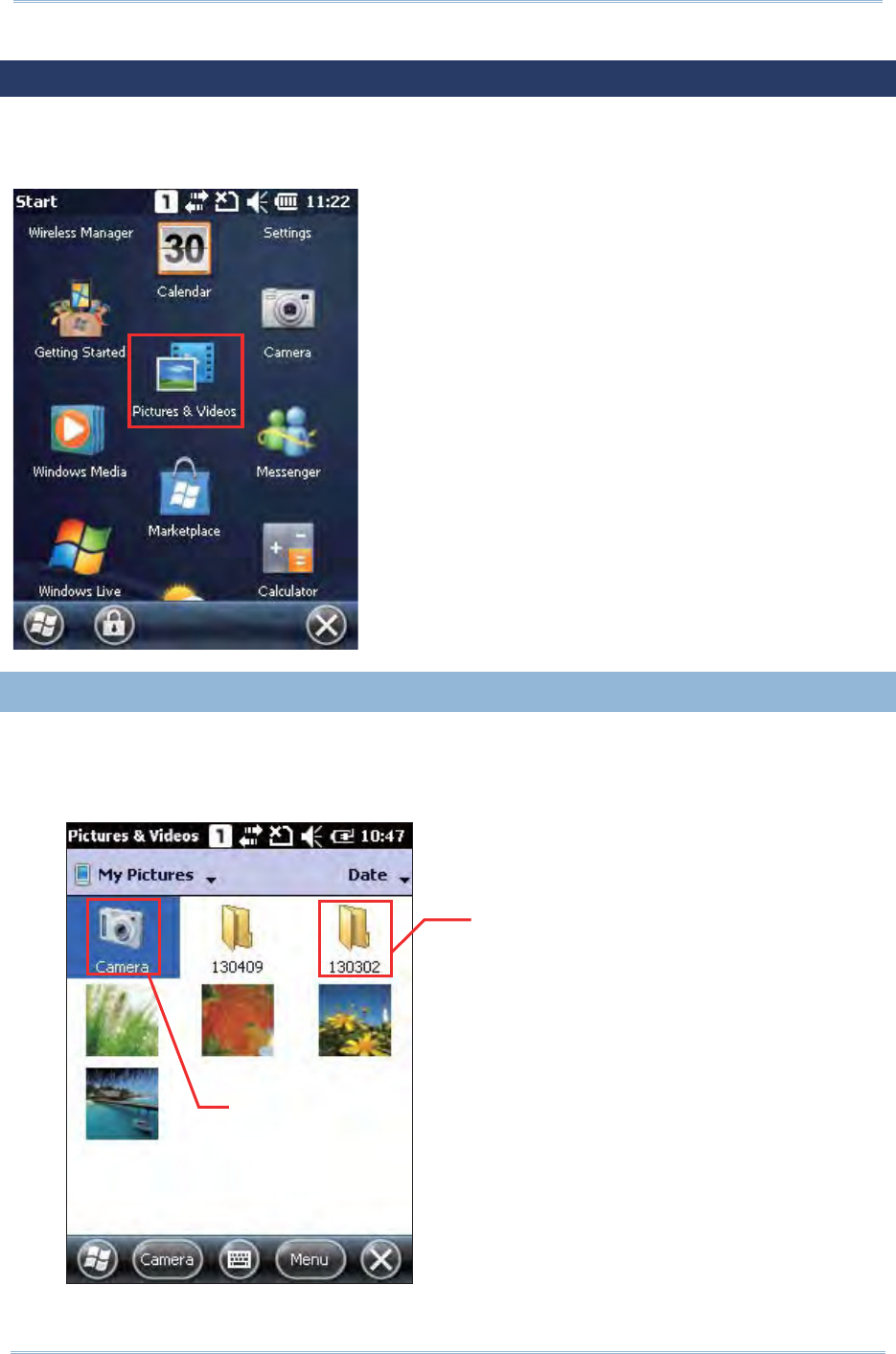
155
Chapt er 8 Using Camera
8.5. PICTURES & VIDEOS
Tap Star t Scre en | Pict ure s & V ideos to open t he default im age folder \ My Device\ My
Docum ent s\ My Pict ures.
8.5. 1. VIEW AN IMAGE
1 . Locat e the t arget folder and the desired pict ure.
The subfolders are nam ed wit h the dat e YYMMDD (2-digit year, 2-digit m ont h and
2- digit date) which im ages were t aken.
Shortcut to
Cam er a
Subfolder in
date form at
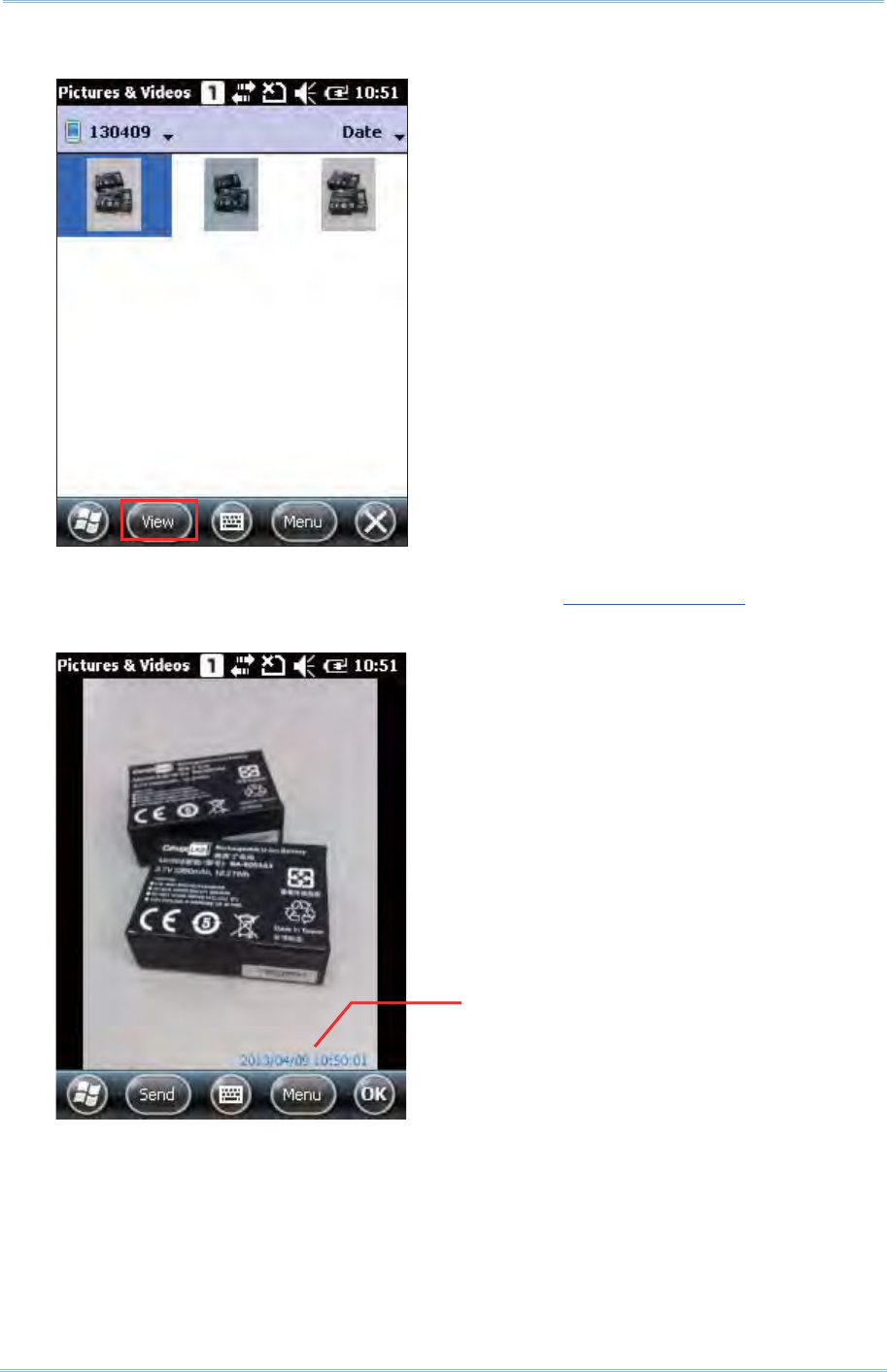
156
9200 Mobile Comput e
r
Ref erence Manual
2 . Select a desired pict ure and tap View at the bott om of the screen.
3 . Tap M e n u on the soft key bar to set the pict ure as background, start a slide show,
beam pictures, edit or rot ate pict ures, etc. Refer to Advanced Set t ings.
Tap Send on the soft key bar to send t he picture via t ext m essage or e- m ail.
4 . Tap OK to close t he current window.
Tim e St am p is displayed on the
lower ri
g
ht of each
p
icture
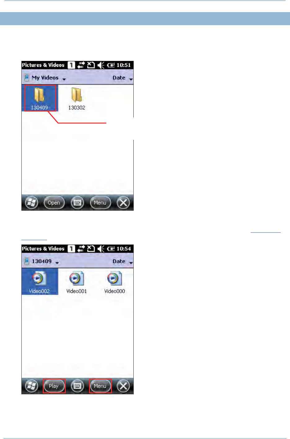
157
Chapt er 8 Using Camera
8.5. 2. PLAYBACK A VIDEO
1 . Locat e the t arget folder and the desired videos.
The subfolders are nam ed wit h the dat e YYMMDD (2-digit year, 2-digit m ont h and
2- digit date) when videos were recorded.
2 . Select a desired video and tap Play on the softkey bar..
Tap Men u on t he softkey bar to edit, send or beam videos, et c. Refer t o Advanced
Set t ings.
3 . The video will be played in Windows Media player. Tap [
²
] to end t he application.
Subfolders in
date form at
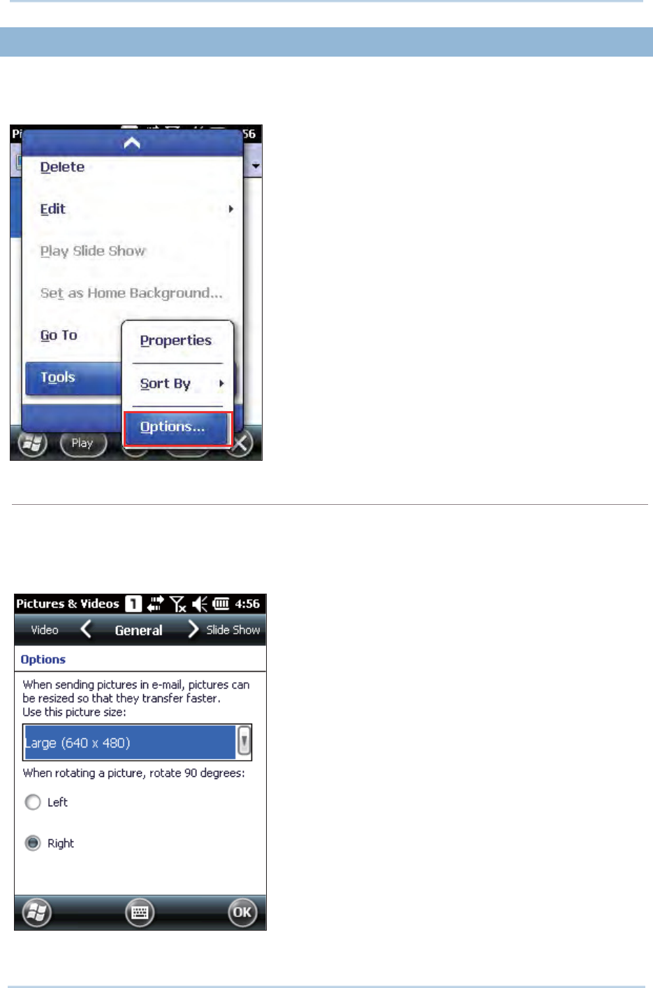
158
9200 Mobile Comput e
r
Ref erence Manual
8.5. 3. ADVANCED SETTINGS
Under My Pict ures or My Video screen, t ap Me n u | Tools | Opt ions to open advanced
set t ings.
General tab
When sending a pict ure by e-m ail, it can be resized in favor of the t ransfer speed. You
m ay tap the drop-down list to select a desired picture size if necessary.
You m ay also change the rot at ion direction of t he pict ure in t he General t ab configurat ion
screen.
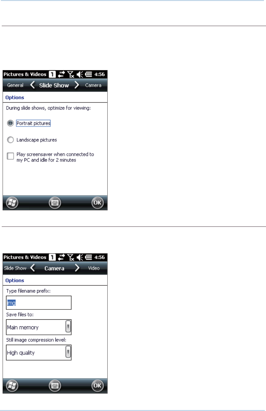
159
Chapt er 8 Using Camera
Slide Show tab
By default, slide shows are played in Port rait view. You m ay change t o use landscape
view inst ead t o m ake pictures properly fit the screen.
I f you select “ Play screensaver when connected to m y PC and idle for 2m inut es”, pict ures
st ored in the default im age folder “ \ My Device\ My Docum ent s\ My Pictures” will be used
in a slideshow screensaver on the m obile com puter.
Camera tab
All st ill im ages are prefixed wit h “im g” and saved t o t he m ain m em ory at high
com pression level by default . You m ay change the prefix, save files to your m em ory
card, or adjust the com pression.
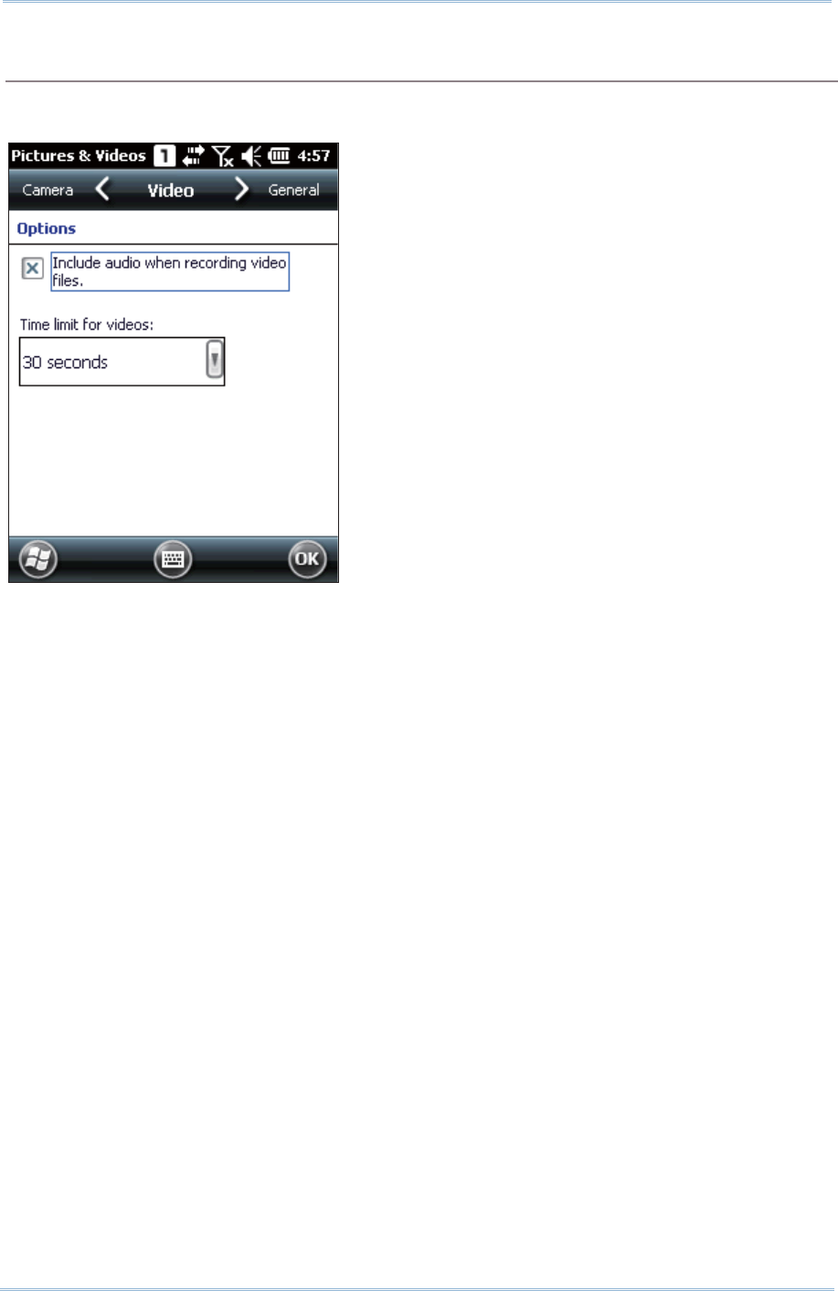
160
9200 Mobile Comput e
r
Ref erence Manual
Video tab
While recording a video, audio sound will be included. You m ay disable the check box or
set a t im e lim it for videos so t hat the file size can be reduced.
Tap [ OK] to save the current set t ings and ret urn to the previous window.

161
This chapter int roduces m anufact urer- developed applications that are preinst alled on the
m obile com puter to st rengt hen syst em m anagem ent and m ake t he m obile com puter
m ore com petent.
Chapter 9
MORE APPLICATIONS
IN THIS CHAPTER
9.1ʳGPS Receiver............................................................162
9.2ʳBut t on Assignment .................................................... 163
9.3ʳMobile Ghost ............................................................ 166
9.4ʳTim e Sync Utility ....................................................... 170
9.5ʳSignature Utility........................................................172

162
9200 Mobile Comput e
r
Ref erence Manual
9.1. GPS RECEIVER
The 9200 Mobile Com put er is equipped wit h a GPS ant enna for obt aining location and
tim e inform at ion from t he Global Posit ioning System (GPS). Since the m obile com puter
does not com e wit h any preinstalled navigat ion soft ware, you m ay need to purchase
third- part y navigation soft ware separately.
The GPS receiver hosted on t he m obile com puter uses COM 7 to output NMEA m essages,
as long as t he COM port is opened. I n your application, open the COM port wit h the
correct configuration.
The table below lists the configuration of the integrated GPS receiver:
Serial Configuration COM Port Settings
Baud Rate 4800
Dat a Bit s 8
Par ity None
St op bit s 1
Note: For m ultiple GPS- enabled program s to access GPS dat a, t ap St a rt Scre en |
Settings | Syst e m and select Ex t e r na l GPS. Specify a program port and t he
correct hardware port.
I n order to speed up st art-up t im e, we suggest you t o download the ephem eris
inform at ion for init ial set up. Go t o St art Scree n | Settings | Syst e m and select GPS
Manager t o update t he ephem eris.
163
Chapt er 9 More Applicat ions
9.2. BUTTON ASSIGNMENT
Use Button Assignm ent to re- define the functions of physical keys to have t hem t rigger
different functions. For inst ance, you can assign a key to sim ulate another key’s
behaviour, to launch a specific program , or t o deliver effect s of a specific key code.
Reassignable keys include:
Side t riggers ( Left and right scan keys)
Application key (App Key)
[ -] ( Hyphen) key
[ .] ( Period) key.
9.2. 1. REASSIGN PHYSICAL KEYS
1 . Tap Sta r t Scr een | Se tt in gs | Syst em | But ton Assignm en t .
A screen shows with a pict ure of t he m obile com put er and its reassignable
physical keys.
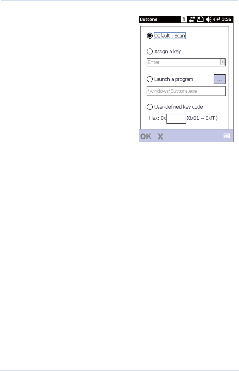
164
9200 Mobile Comput e
r
Ref erence Manual
2 . Tap the label of t he key you wish to
reassign.
Available options include:
Default : Recovers t he default settings.
Assign a key: Defines a certain key t o
act as anot her key. Select the desired
funct ion in t he drop-down list. Opt ions
include:
Ent er
Scan
Esc
Delet e
Backspace
Space
Tab
F1~ 12
St art Menu
Alt
OEM_Key1(0xE9)
OEM_Key2(0xEA)
OEM_Key3(0xEB)
OEM_Key4(0XEC)
OEM_Key5(0XED)
OEM_Key6(0xEE)
OEM_Key7(0xEF)
OEM_Key8(0xF0)
OEM_Key9(0xF1)
OEM_Key10( 0x2A)
*
#
Send( VK_TTALK)
End(VK_END)
Up
Dow n
Left
Right
TAB
Volum e Up
Volum e Down
OK
Hom e(VK_HOME)
Hom e(VK_HOME)
165
Chapt er 9 More Applicat ions
Fn+ ESC(0xF5)
F13~ 24
Hom e(VK_LWI N+ VK_APP)
-
.
Launch a program : Defines a key to quick- launch an applicat ion.
Use the Browse button t o select an execut able file to open aft er pressing t he
key, or m anually ent er t he path of t he desired file.
User- defined key code: Allows users t o change t he key function as desired by
entering the hex value of the target key.
3 . Tap OK on t he m enu bar ( locat ed at the bot t om of the screen) to apply the
changes, or t ap Xt o discard t he set t ings.
4 . Tap OK on the soft key bar t o store t he set t ings and exit t he application.
9.2. 2. RESET PHYSICAL KEYS TO DEFAULT
Tap the Rese t but ton on the lower right of t he screen t o change all list ed key funct ions
back t o default .
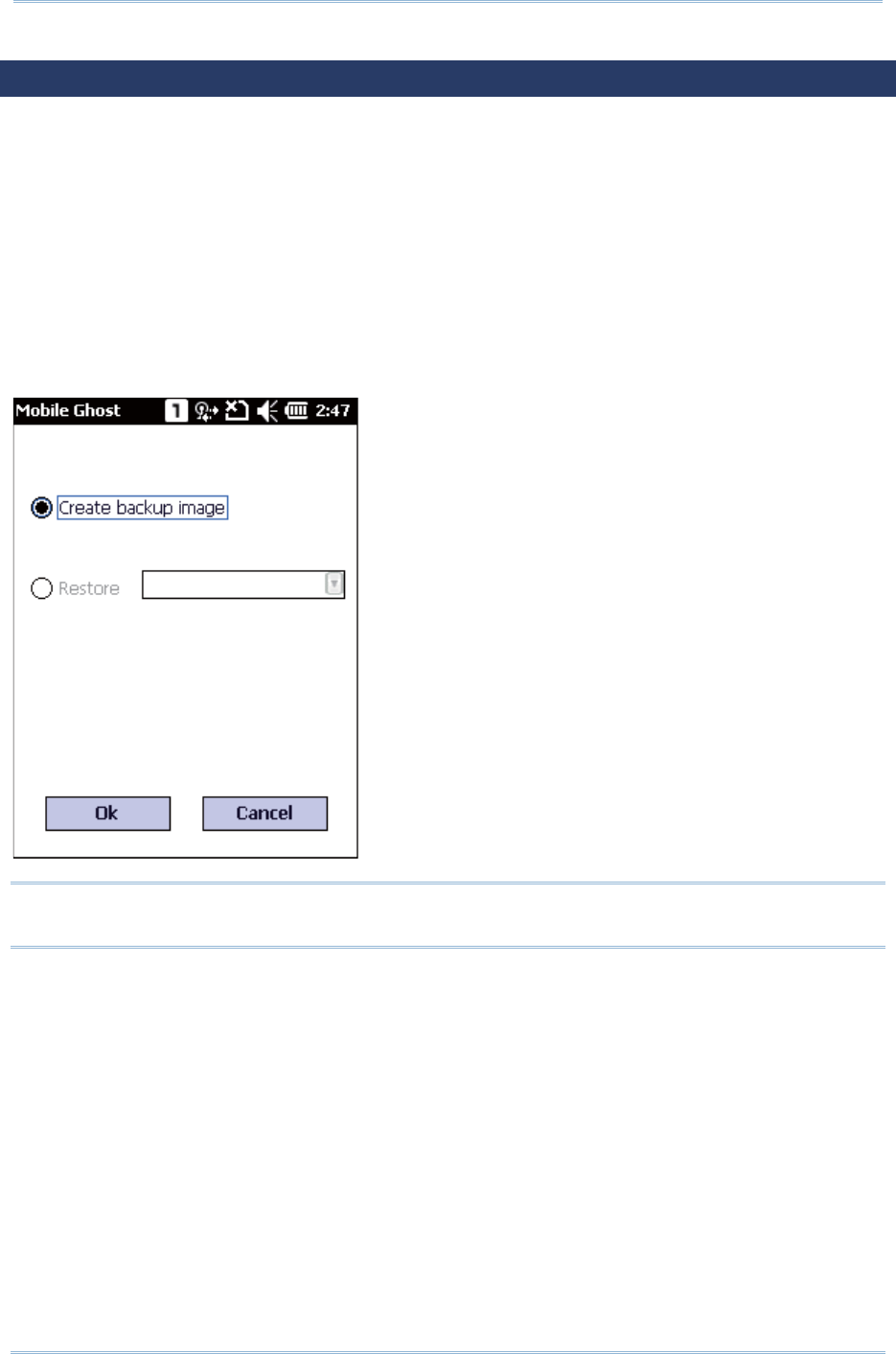
166
9200 Mobile Comput e
r
Ref erence Manual
9.3. MOBILE GHOST
Mobile Ghost is a syst em cloning tool t hat copies user dat a and regist ry set tings on your
m obile com puter in the form of a backup image. You m ay use the creat ed backup im ages
for full rest orat ion of regist ry set t ings and user files. Through backup im age creation,
syst em configuration and application set t ings can be reserved at a state when t he syst em
is st able. This is especially helpful when the system encounters unexpected crash dow n
or hardware/ software error. I n addit ion, you m ay use this t ool to copy syst em set t ings
and user files on a certain m obile com puter and write them to a set of ot her m obile
com puters so all resem ble t he sam e user environm ent.
To open the Mobile Ghost, tap St art Scree n | Ciphe rLa b Ut ilit ies | Mobile Ghost . Two
screen opt ions show for creating a backup im age, or restoring a previously creat ed one.
Note: As long as any changes are m ade to the system configurat ions and set tings, you
m ust create a new backup im age for t he syst em regist ry to be updated.
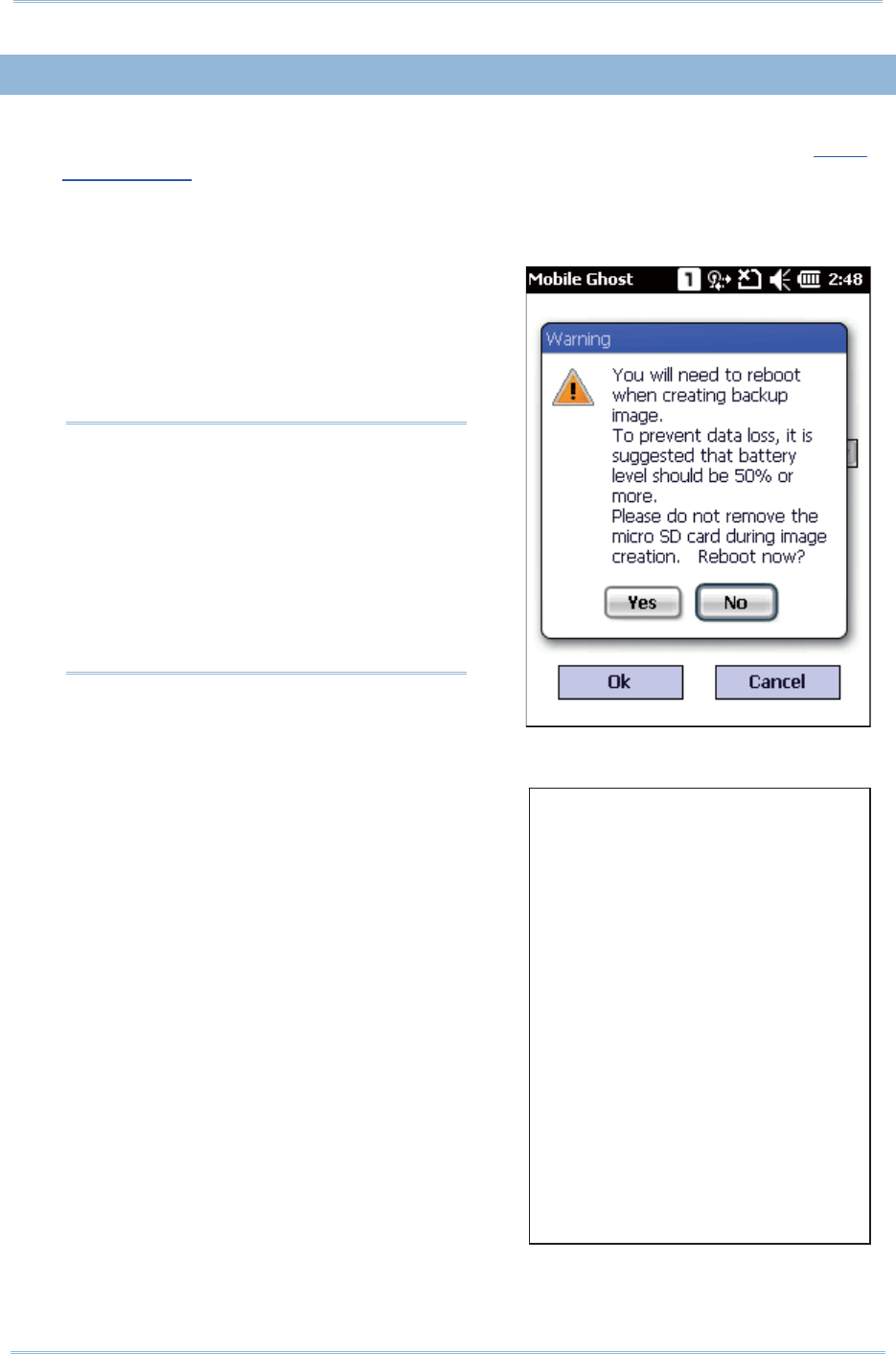
167
Chapt er 9 More Applicat ions
Note:
( 1) To prevent data loss during
backup, m ake sure syst em
battery level is sufficient ,
preferably over 50% , or m ake
sure the m obile com puter is
connect ed t o external power.
( 2) Do not rem ove the m icroSD card
during backup im age creation.
[ St ar t bac kup]
( Bac kup i n pr ogr ess)
Pl eas e wai t f or a f ew mi nut es……
……………………
9.3. 1. CREATE BACKUP IMAGE
1 . To creat e a backup im age for syst em registry and set t ings, a m em ory card is
required. I nsert a m icroSD card into the SD card slot as described in Using
Mem ory Card.
2 . Open Mobile Ghost by tapping Star t Scre en | CipherLa b Ut ilit ies | M obile
Ghost .
3 . Check Crea t e back up im a ge and t ap OK.
A warning m essage shows not ifying that
syst em reboot ( restart ) is needed for
backup im age creation. Tap Ye s to
continue and N o t o abort .
4 . The m obile com puter restart s, and t he
backup procedure begins short ly. An
on- screen m essage appears stating that
backup is currently under progress.
When backup is com plet ed, a .bgo file
nam ed in date form at (YYYY- MM-DD_001)
will be created on t he m icroSD card. The
m obile com puter will rest art once m ore.
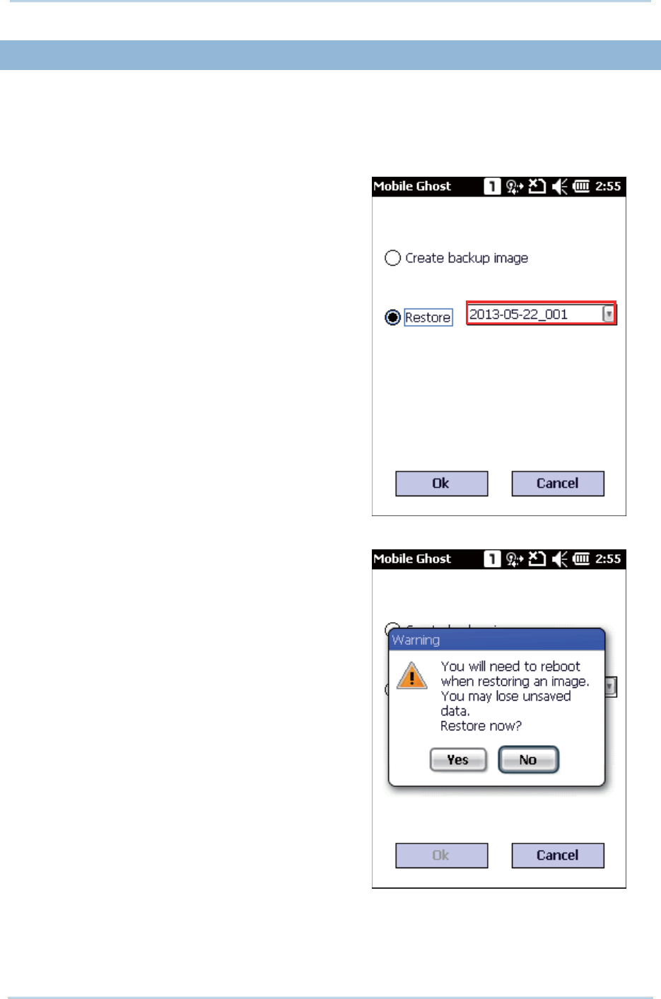
168
9200 Mobile Comput e
r
Ref erence Manual
9.3. 2. RESTORE BACKUP IMAGE
Restoring a backup im age will change system settings back t o t he conditions when the
backup im age was creat ed.
1 . To rest ore a backup im age which was previously created, m ake sure the m icroSD
card cont aining t he desired backup im age is inserted on t he m obile com puter.
2 . Open Mobile Ghost by tapping St a rt
Screen | Ciphe rLa b Ut ilit ies | M obile
Ghost .
Check t he Restore option and select a
backup im age in the drop-down list . Tap
OK to confirm .
3 . A warning m essage appears rem inding
that system reboot (restart ) is needed for
backup im age restoration. Make sure all
user dat a and tasks are saved before
tapping Yes t o confirm rest oration.
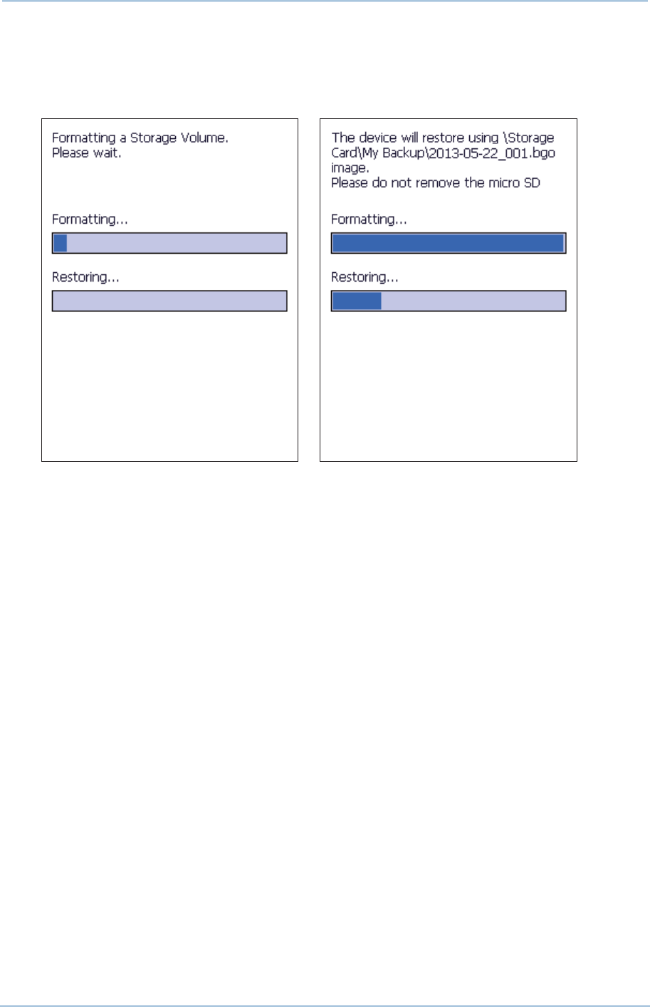
169
Chapt er 9 More Applicat ions
4 . Device storage begins form at t ing. Once com plet ed, rest oration start s using t he
select ed backup im age.
When restorat ion is com plet ed, the m obile com puter will rest art with system
registry and set t ings of t he select ed backup im age applied.
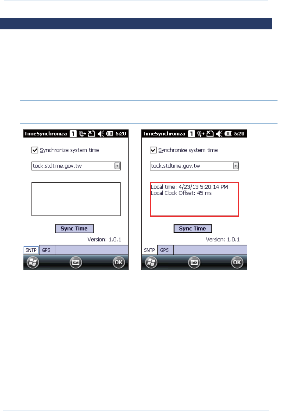
170
9200 Mobile Comput e
r
Ref erence Manual
Note: To sync tim e with an NTP server, m ake sure your m obile com puter is wirelessly
connect ed, and the “Synchronize syst em tim e” checkbox is select ed.
9.4. TIME SYNC UTILITY
Use this to sync syst em t im e with a server, eit her via wireless connect ion t o an NTP
server or via GPS signal detect ion.
To synchronize syst em tim e on t he m obile com puter:
1 . Open t im e sync utility by tapping St a rt Scr een | Se t t in gs | Syst e m | Tim eSync.
2 . To sync tim e with an NTP server, select t he preferred NTP server and tap Sync Tim e.
The sync result s will appear in the cont ent field short ly.
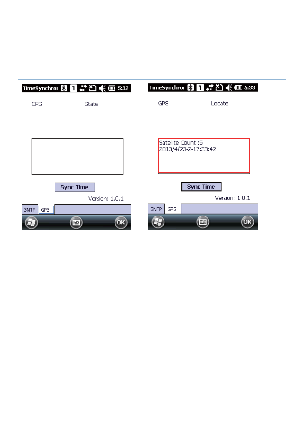
171
Chapt er 9 More Applicat ions
Note: To sync tim e via GPS signal, m ake sure your m obile com puter is locat ed in an
open area wit h a clear view of the sky, and the GPS software port is correct ly
set under Ext ernal GPS.
3 . To sync tim e via GPS signal, open GPS tab and t ap Sync Tim e.
The m obile com puter will st art t o det ect available GPS signals and ident ify t he correct
tim e. Sat ellite count and t im e results will appear in the content field below.
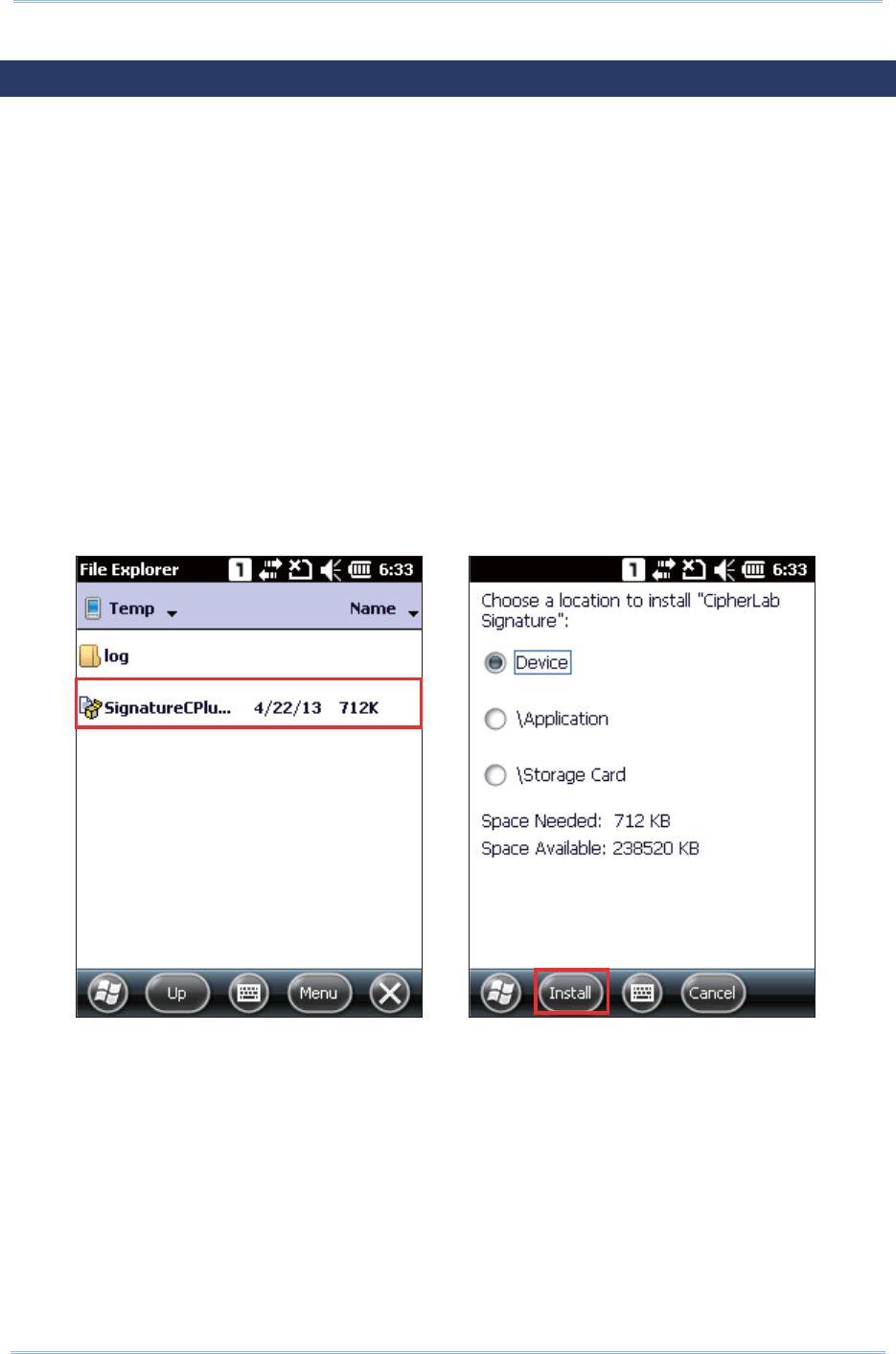
172
9200 Mobile Comput e
r
Ref erence Manual
9.5. SIGNATURE UTILITY
Signa tur e ut ilit y captures, views, and edits signature files st ored on the m obile
com puter.
Signa tur e ut ilit y is provided in two file form ats, .cab and .exe, on t he CD- ROM shipped
along wit h the m obile com puter. I nst all the applicat ion on the m obile com puter according
to your needs.
.CAB FILE INSTALLATION
1 . I nsert t he product CD into the CD-ROM drive on your PC.
2 . Connect the m obile com put er with your PC via ActiveSync.
3 . Copy the .cab file from your PC to a path of your selection on the mobile
com puter.
4 . On the m obile com puter, use File Explorer to locate the copied .cab file.
5 . Tap the .cab file to start inst allat ion. Select the location to st ore the applicat ion
and tap I n st a ll.
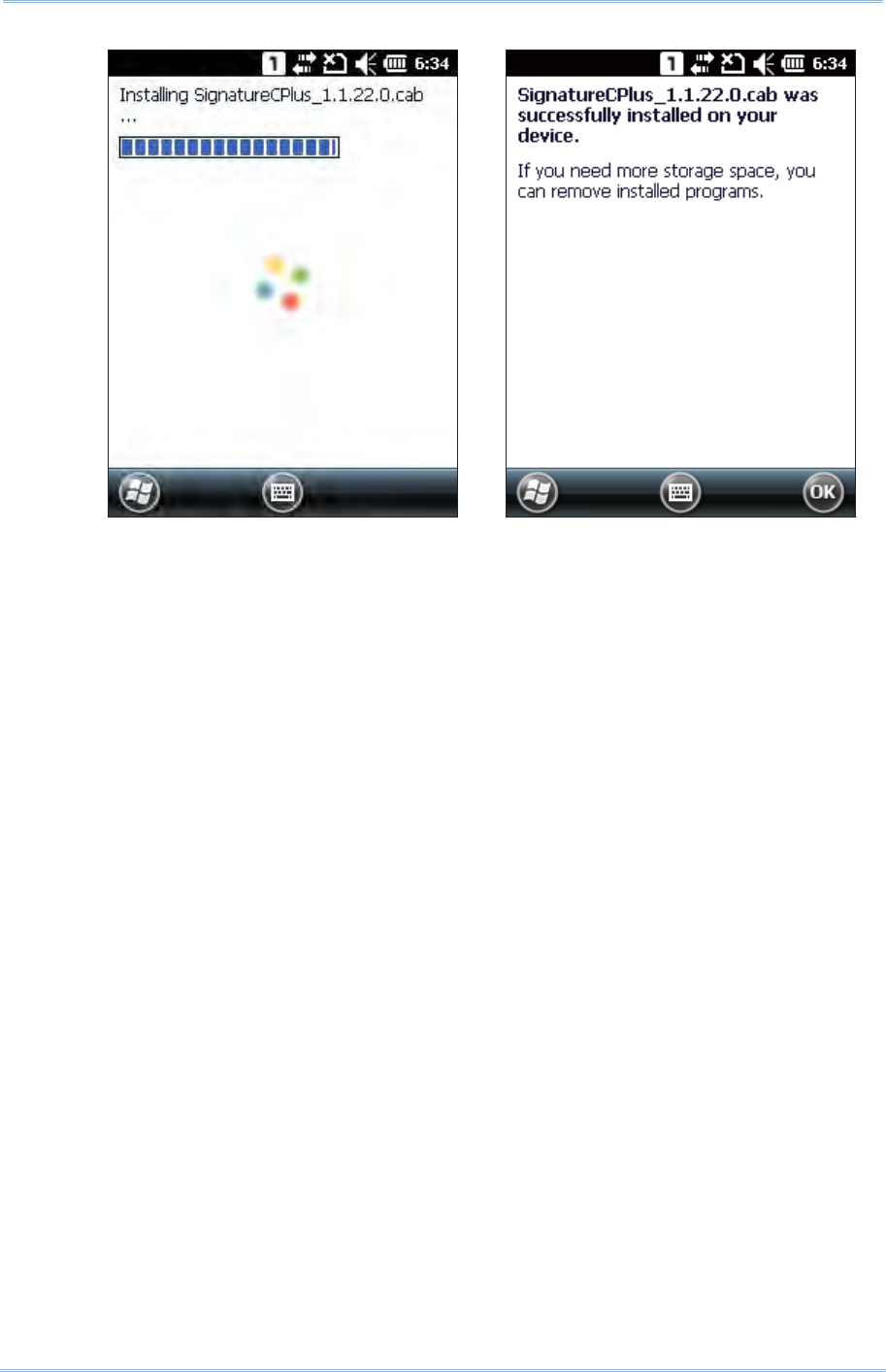
173
Chapt er 9 More Applicat ions
6 . Signa t ure utilit y is inst alled on t he m obile com puter’s Start Screen.
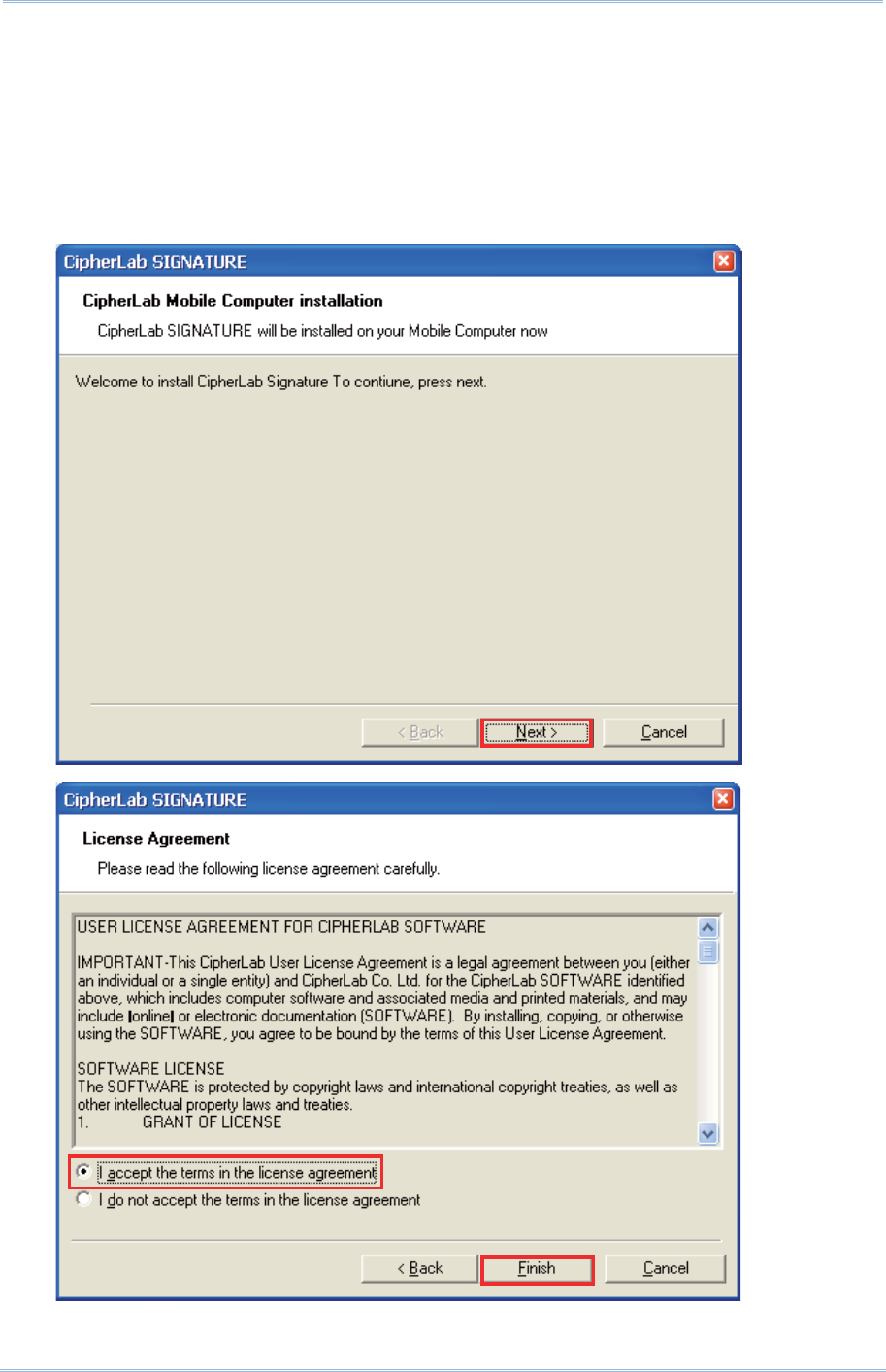
174
9200 Mobile Comput e
r
Ref erence Manual
.EXE FILE INSTALLATION
1 . I nsert t he product CD into the CD-ROM drive on your PC.
2 . Connect the m obile com put er with your PC via ActiveSync.
3 . On your PC, double- click t he .exe file t o start the installat ion. An inst allation
wizard appears to guide you t hrough the process.
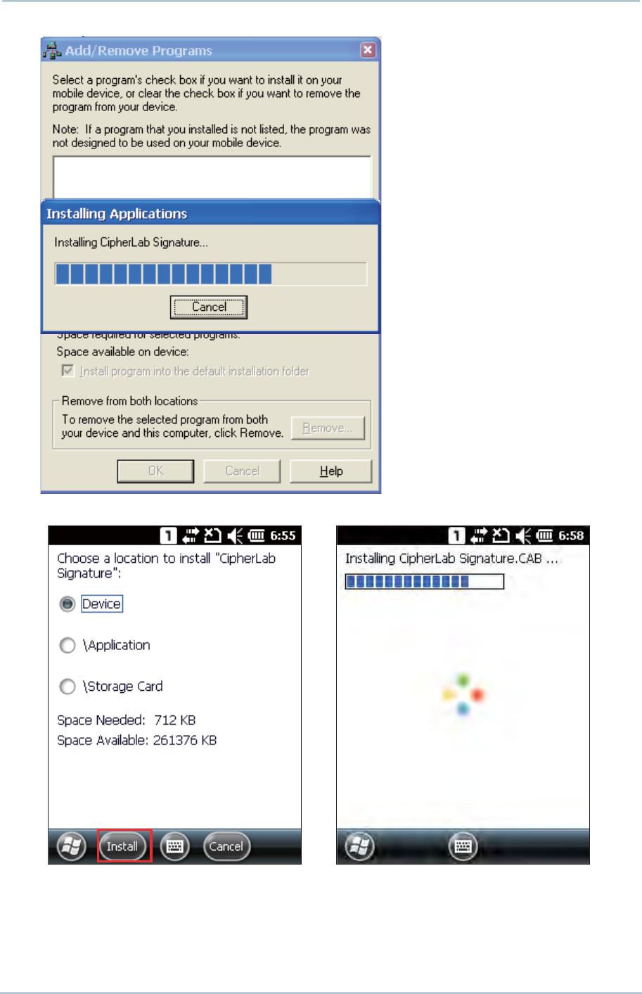
175
Chapt er 9 More Applicat ions
4 .
5 . Signa tur e ut ilit y is installed on t he m obile com puter’s Start Screen..
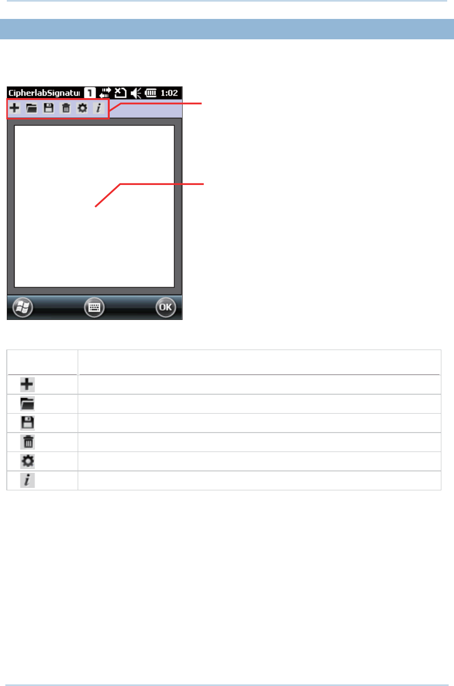
176
9200 Mobile Comput e
r
Ref erence Manual
9.5. 1. CAPTURING A SIGNATURE
Aft er inst alling Signatu re ut ilit y on your m obile com puter, open the application from
St art Scree n | Signatur e. The applicat ion opens showing a toolbar and a signing area.
Toolbar funct ions include:
Toolbar icon Description
Creat es a new signature file.
Loads an existing signature file.
Saves the creat ed/ edit ed signat ure t o an im age file (BMP, JPG or Locus form at) .
Clears the signing area.
Opens preferences set tings.
View s ut ility info including developer and soft ware version.
Toolbar
Signing area
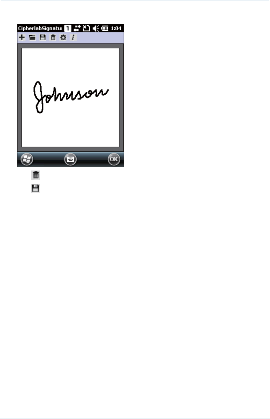
177
Chapt er 9 More Applicat ions
1 . Use the stylus to sign your signature in t he signing area.
2 . Tap t o clear the signature and sign a new one if necessary.
Tap t o save the signat ure as an im age file.
3 . Tap OK to exit the program .
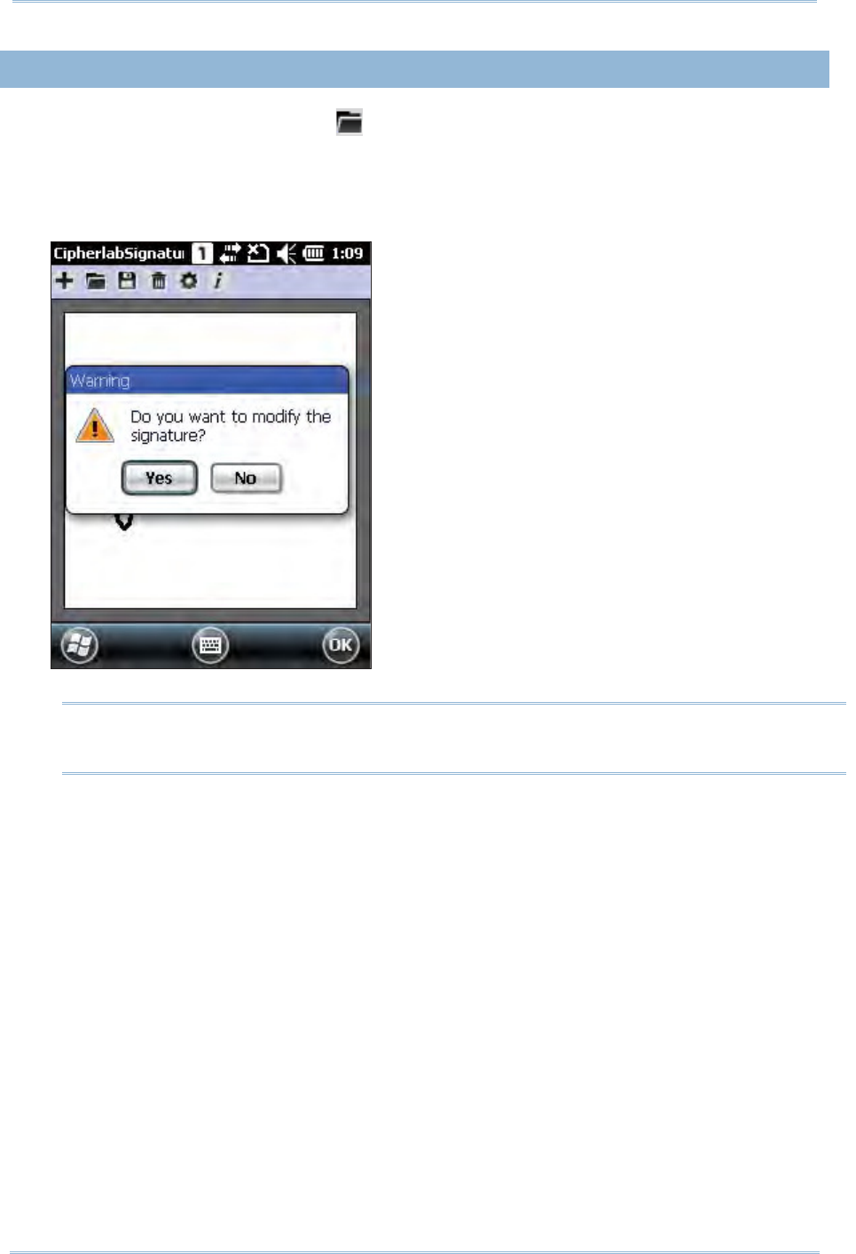
178
9200 Mobile Comput e
r
Ref erence Manual
9.5. 2. VIEWING A SIGNATURE
1 . To view a signature im age, tap on t he m enu bar and select an im age t o load.
The im age will be displayed along wit h a m essage asking whether you would like t o
m odify the picture.
2 . Tap Yes t o change the signature if necessary.
Note: The m axim um size for resolution of an im age file is 640x480 pixels. Any im age
larger than t his size will be unable t o load.
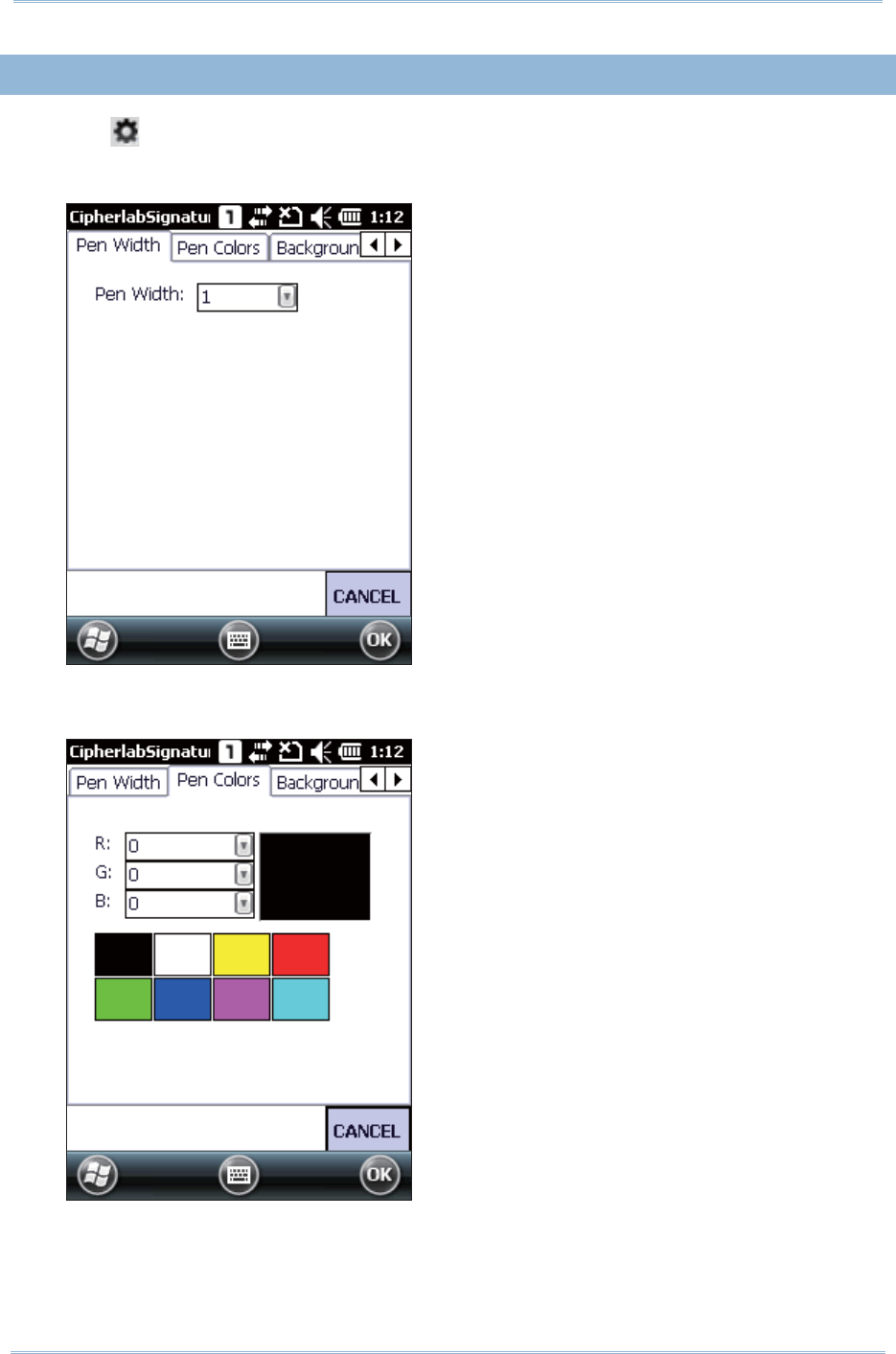
179
Chapt er 9 More Applicat ions
9.5. 3. CHANGING SIGNATURE SETTINGS
1 . Tap t o configure signat ure set tings if necessary
Pen Width tab: Set t he pen widt h ( 1-5 pixels) for signing. The default pen widt h is 1.
Pen Colors tab: Set t he pen color using t he available colors, or enter a new color in RGB
value ( 0-255) . The default pen color is black
Background Colors t ab: Set t he background color using t he available colors, or ent er a
new color in RGB value ( 0-255). The default background color is white.
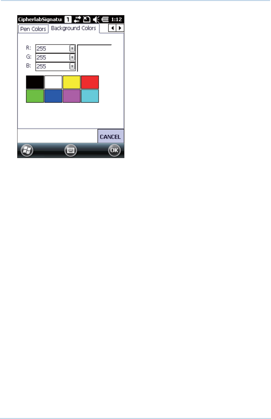
180
9200 Mobile Comput e
r
Ref erence Manual
2 . Aft er done configuring signature set t ings, tap OK on the soft key bar t o save t he
changes.

181
PLATFORM, PROCESSOR & MEMORY
Operating System & CPU
Windows Version Microsoft Windows Em bedded Handheld 6.5
CPU Qualcom m MSM7225- 1 at 528 MHz
Memory
ROM 512 MB NAND flash m em ory
RAM 256 MB DDR SDRAM
Expansion Slot One m icroSD card slot (256MB t o 4GB)
SDHC supported (4GB t o 32 GB)
COMMUNICATION & DATA CAPTURE
Communication
USB Client USB Client 2.0 Specification
WPAN Built -in m odule for Bluetoot h version 2.1 + EDR Class I I connect ivit y
WLAN Built- in m odule for 802.11b/ g networking
WAPI support for China only
WWAN Ordering Option - built - in m odule for GSM/ EDGE/ UMTS/ HSPA
GPS Built -in GPS with AGPS support, ephem eris downloadable
Data & Image Capture
Digital Cam era 3.0 CMˢS wit h LED flash and auto focus
Barcode Reader Ordering options include CCD
1D Laser
2D I m ager
HF RFI D Reader Support s I SO14443A (Mifare) and B, I SO 15693
SPECIFICATIONS

182
9200 Mobile Comput e
r
Ref erence Manual
ELECTRICAL CHARACTERISTICS
Batteries
Main Bat t ery Pack Rechargeable Li-ion batt ery – 3.7 V, 3300 m Ah
Power Adaptor
I nput AC 100~ 240 V, 50/ 60 Hz Power Supply Cord wit h
Universal Power Adapt or Output DC 5 V, 4 A
Working Time (Laser, testing cycle = 20 seconds)
Conditions include: scanning com plete wit hin one second, backlight on during scanning. Scanning,
com puting and dat a transfer finished within 20 seconds wit h GSM and WiFi on. I n this m ode,
batt ery power will support working t im e for up t o 12 hours.
PHYSICAL CHARACTERISTICS
Color Touch Screen Display
Display 2.8” Transflective/ Transm issive TFT-LCD, 65k colors
Resolut ion QVGA (240 u 320 pixels)
Keypad
Layout 28-key Alphanum eric keypad wit h LED backlight
Notifications
St atus LED Two LEDs:
Left: Charging stat us (Red/ Gr een) and Scanner Good Read
( Green, flash once)
Right: Scanner Light Beam ( Orange)
Audio I ntegrat ed wit h one speaker, m icrophone and receiver
CTI A Headset jack – for 3.5 m m ear phone
Bluet oot h headset supported
Vibrat or 0.45G force, for scanner Good Read and system notificat ions
Dimensions & Weight
Dim ensions 175 m m (L) x 60 m m ( W) x 34 m m ( H)
Weight 310 g ( Laser , including bat tery)

183
Specificat ions
ENVIRONMENTAL CHARACTERISTICS
Temperature
SM1 - 10 ° C t o 50 ° C ( t ransm issive), -20 ° C t o 50 ° C ( transflect ive)
SE955 -10 ° C t o 60 ° C ( t ransm issive) , -20 ° C to 60 ° C ( transflect ive)
Oper ating
SE4500 -10 ° C to 55 ° C ( transm issive) , -20 ° C to 55 ° C ( transflect ive)
St orage - 20 ° C t o 60 ° C (t ransm issive), -30 ° C t o 70 ° C ( transflect ive) ,
both wit hout bat tery, wit h hum idity 5% to 85% (non- condensing)
Charging 0° C t o 40° C
Humidity
Oper ating 10% to 90% (non- condensing)
St orage 5% to 85% ( non- condensing)
Resistance
I m pact Resistance Mult iple 1.5m drops ont o concret e
Tum ble Test 1000 tim es at 0.5 m per applicable I EC t um ble specifications
Splash/ Dust Resistance IP65 per applicable I EC sealing specificat ions
PROGRAMMING SUPPORT
Development Environment & Tools
I ntegrat ed Developm ent
Environm ent
Visual St udio 2008
Visual St udio 2005
Soft ware Developm ent Kit Microsoft SDK
System API (DLL) for syst em configurat ion
Reader API (DLL) for reader configurat ion
Software & Utilities
CipherLab Software Package Reader Configurat ion
Signature
AppLock
MI RROR Browser for web applicat ion
Term inal Emulat ion
Third-party Software SOTI MobiCont rol for r em ote device control
Naurt ech CETerm – Term inal em ulat or (3270, 5250, VT) and
industrial web browser
Wavelink Em ulat or
Kalipso

184
9200 Mobile Comput e
r
Ref erence Manual
ACCESSORIES
Accessory Options
LCD Prot ect ive Film
Snap-on Charging & Com m unicat ion Cable (USB or RS- 232)
Charging & Com m unication Cradle