Cisco Linksys BEFW11S4V32 Wireless Access Point Router with 4-Port Switch User Manual Part 1
Cisco-Linksys, LLC Wireless Access Point Router with 4-Port Switch Users Manual Part 1
Contents
- 1. DoC Statement
- 2. Users Manual Part 1
- 3. Users Manual Part 2
Users Manual Part 1
The LAN Indicators
WLAN Act Green. This LED indicates wireless activity.
WLAN Link Green. This LED indicates that the Router’s wireless func-
tions have been enabled through the Web-based utility.
Power Green. This LED indicates that the Router’s power is on.
Link/Act Green. This LED serves two purposes. When this LED is lit
continuously, this indicates that the Router is connected to a
device through the corresponding port (1, 2, 3, or 4). A blink-
ing LED indicates that the Router is actively sending or
receiving data over that port. When the Uplink Port is in use,
the LED for Port 4 will be lit continuously.
6
The Wireless Access Point Router’s LEDs
TThhee RReesseett BBuuttttoonn
Pressing the Reset Button and holding it in for a few seconds will clear all
of the Router’s data and restore the factory defaults. This should be done
only if you are experiencing heavy routing problems, and only after you
have exhausted all of the other troubleshooting options. By resetting the
Router, you run the risk of creating conflicts between your PCs’ actual IP
Addresses and what the Router thinks their IP Addresses should be. You
may be forced to reboot each network PC.
If the Router locks up, simply press the reset button or power it down for
three to five seconds by removing the power cable from the Router’s
Power Port. Leaving the power off for too long could result in the loss of
network connections.
Figure 1-2
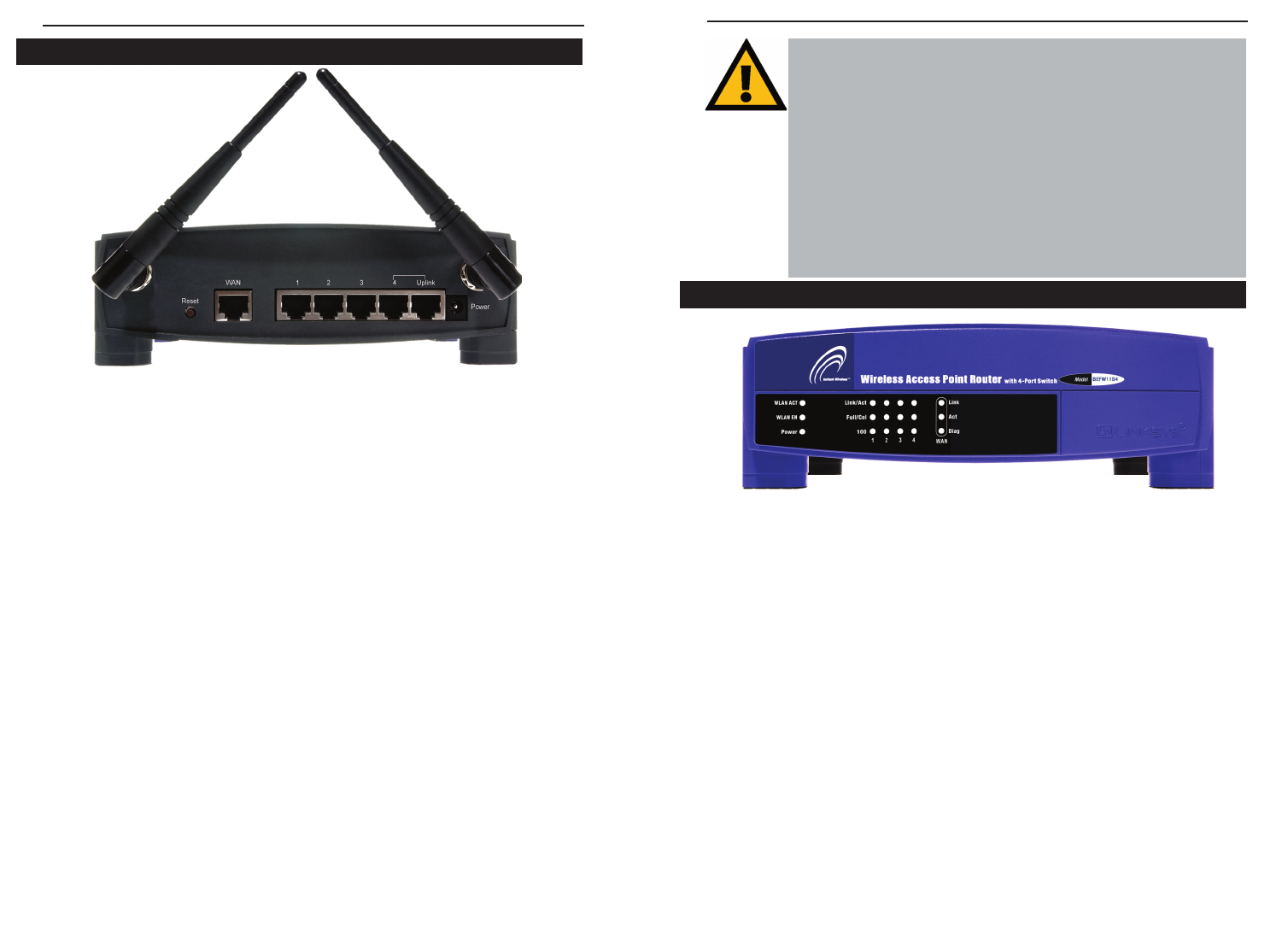
The Router’s rear panel (as shown in Figure 1-1) is where all of its connections
are made.
WA N The WAN (Wide Area Network) Port is where you will con-
nect your cable or DSL modem with an Ethernet cable. Your
modem connection will not work from any other port.
Ports 1-4 These four LAN (Local Area Network) ports are where you
will connect networked devices, such as PCs, print servers,
and any other Ethernet devices you want to put on your net-
work. If Port 4 is being used, the Uplink Port will not work.
Uplink The Uplink Port is where you can expand your network by
connecting to another switch or hub. Uplinking to another
switch or a hub is done by simply running a cable from the
Uplink Port to the other device. The Uplink Port is shared
with Port 4. If the Uplink port is being used, Port 4 will not
work.
Power The Power Port is where you will connect the included AC
Power adapter.
Antenna Jacks The Antenna Jacks are where the included antennas are con-
nected.
Figure 1-1
The Wireless Access Point Router’s Ports
Instant WirelessTM Series Wireless Access Point Router with 4-Port Switch
5

Chapter 2: Connecting the Router
Before plugging everything together, it’s always a good idea to have everything
you’ll need to get the Router up and running. Depending upon how you config-
ure the Router in Chapter 4: Configuring the Router, you may need some of the
following values from your ISP:
When connecting through a Static IP connection, be sure to have 1) Your
broadband-configured PC’s fixed Internet IP Address, 2) Your broadband-
configured PC’s Computer Name and Workgroup Name, 3) Your Subnet
Mask, 4) Your Default Gateway, and 5) Your Primary DNS IP address.
When connecting through a PPPoE connection, be sure to have 1) Your
PPPoE User Name and 2) Your PPPoE Password.
The installation technician from your ISP should have left this information with
you after installing your broadband connection. If not, you can call your ISP to
request the data.
Once you have the above values, you can begin the Router’s installation and
setup.
Once you are sure that you have the above values on hand, you can begin the
Installation and Setup of the Router.
1. Power everything down, including your PCs, your cable or DSL modem and
the Router.
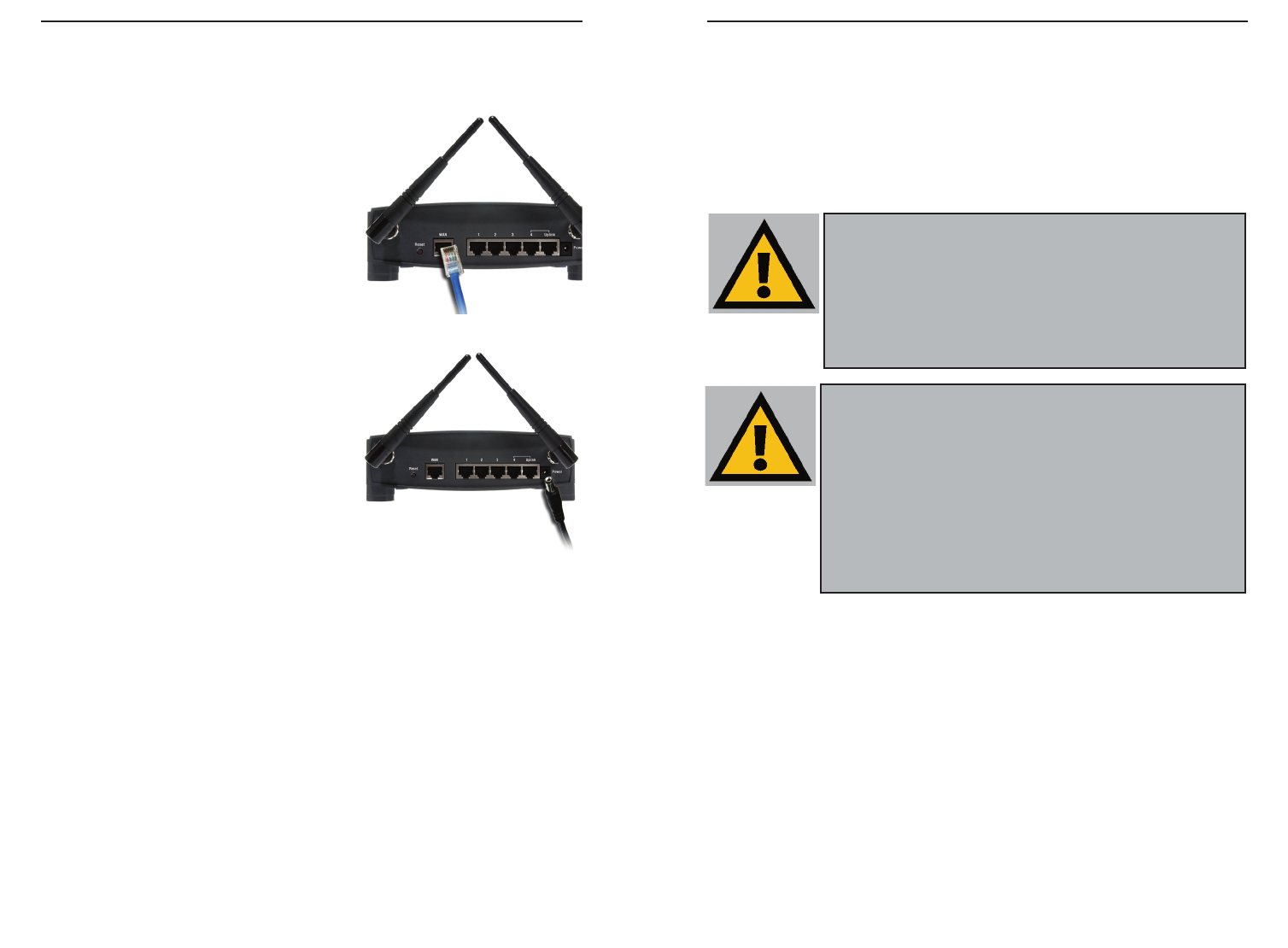
2. Connect an Ethernet cable from one of
your PC’s Ethernet ports to one of the
Router’s LAN ports (as shown in Figure 2-
1). Do the same with all the PCs you wish
to connect to the Router. (LAN Port 4 will
become inactive if you use the Uplink
port.)
In addition to accessing the Router through
an Ethernet connection, a wireless connec-
Before You Start
Full/Col Green. This LED also serves two purposes. When this LED
is lit continuously, the connection made through the corre-
sponding port is running in Full Duplex mode. A blinking
LED indicates that the connection is experiencing collisions.
Infrequent collisions are normal. If this LED blinks too
often, there may be a problem with your connection. Refer to
the Troubleshooting Appendix if you think there is a prob-
lem.
100 Orange. This LED indicates when a successful 100Mbps
connection is made through the corresponding port.
The WAN Indicators
Link Green. This LED indicates a connection between the Router
and your broadband device or network.
Act Green. This LED blinks when the Router is sending or
receiving data over the broadband (WAN) port.
Diag Red. This LED indicates the Router’s self-diagnosis mode
during boot-up and restart. It will turn off upon completing
the diagnosis. If this LED stays on for an abnormally long
period of time, refer to the Troubleshooting Appendix.
7
Connecting Your Hardware Together and Booting Up
Figure 2-1
Instant WirelessTM Series Wireless Access Point Router with 4-Port Switch
8
For Wireless Connections: In addition to accessing the Router through an
Ethernet connection, a wireless connection can be used to access the Router.
After powering on the Router and connecting it to your modem, enter the
Router’s IP Address in the Address field of your wireless PC’s web-browser as
follows: http://192.168.1.1 and press Enter.
IImmppoorrttaanntt::
The Wireless Access Point Router with 4-Port Switch is
configured by default to work out of the box with all Linksys Wireless
Adapters. If you have changed the defaults on your Linksys Wireless
Adapters, or are using other wireless adapters, you must temporar-
ily change your wireless adapter settings to: (SSID = linksys) in
order to initially access the Router wirelessly. After you have
accessed the Router with the default settings, you can change the
router settings to coincide with your Network settings and reset your
adapters.
IImmppoorrttaanntt::
Some ISPs—most notably some cable providers—config-
ure their networks so that you do not have to enter a full Internet
address into your web browser or e-mail application to reach your
home page or receive your e-mail. If your Internet home page
address is something very simple, such as “www”, rather than
“www.linksys.com”, or your e-mail server’s address is something sim-
ilar to “e-mail” or “pop3”, rather than “pop.mail.linksys.com”, you
won’t be able to properly configure the Router until you determine the
actual Internet addresses of your Web and e-mail connections.
You mmuussttobtain this information prior to connecting the Router to
your network. You can obtain this information by contacting your ISP.
10
tion can be used to access the Router. See the “For Wireless Connections”
section that follows these connection instructions.
3. Connect another Ethernet cable from your
cable or DSL modem to the Router’s WA N
port (as shown in Figure 2-2).
4. Connect the Power Adapter (included) to
the Router’s Power port (as shown in
Figure 2-3) and plug the other end into a
power outlet.
• The Power LED will illuminate green
as soon as the power adapter is con-
nected.
• The Diag LED will illuminate red for a
few seconds while the Router goes
through its internal diagnostic test. The
LED will turn off when the self-test is
complete.
5. Power on the cable or DSL modem. Verify
that the power is on by checking the Link LED in the WAN column on the
front of the Router. The Link LED will be illuminated if the power is on and
the modem is ready.
6. Press the Reset button on the back of the Router. Hold the button in for three
seconds, or until the Diag LED illuminates red. This restores the Router’s
default settings.
7. Power on your PC.
The Router is now connected. Continue to the next chapter to configure
your PCs.
Figure 2-2
Figure 2-3
Instant WirelessTM Series Wireless Access Point Router with 4-Port Switch
9