Cisco Systems 102040 Hand Held Wireless Display Terminal User Manual manual
Cisco Systems Inc Hand Held Wireless Display Terminal manual
UserManual.wiki
>
Cisco Systems
>
102040 User Manual
>
Revised Manual
Contents
1.
Manual
2.
Corrected Manual Page showing MPE Separation Distance
3.
Quick Ref Guide Additions
4.
Quick Ref Guide
5.
Teampad 500 System Users Guide
6.
Guide Corrections
7.
Revised Manual
Revised Manual
Navigation menu
Upload a User Manual
Namespaces
Wiki Guide
HTML
PDF
Info
Views
User Manual
Discussion / Help
Navigation

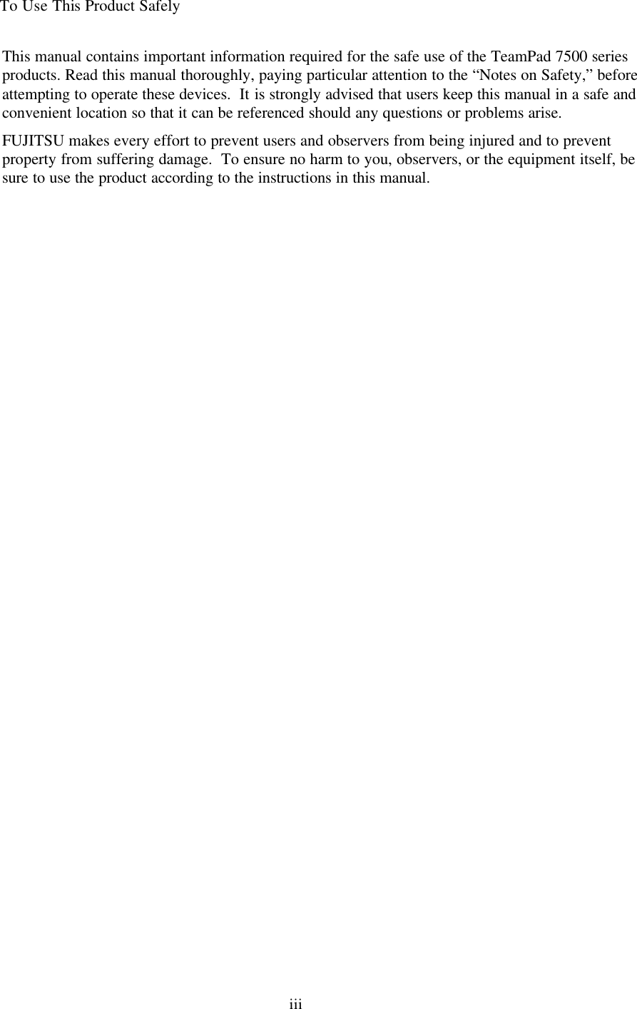
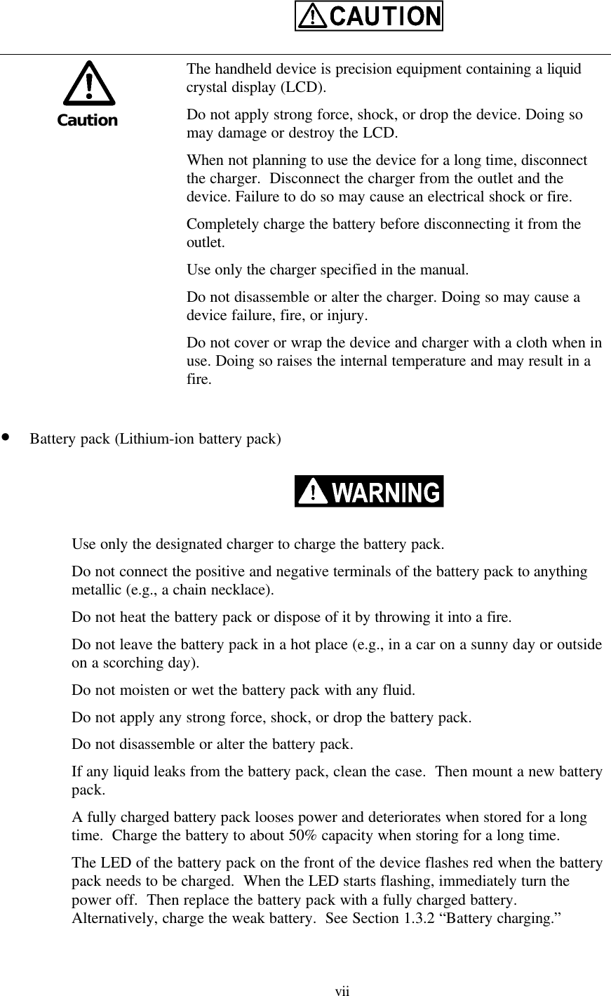
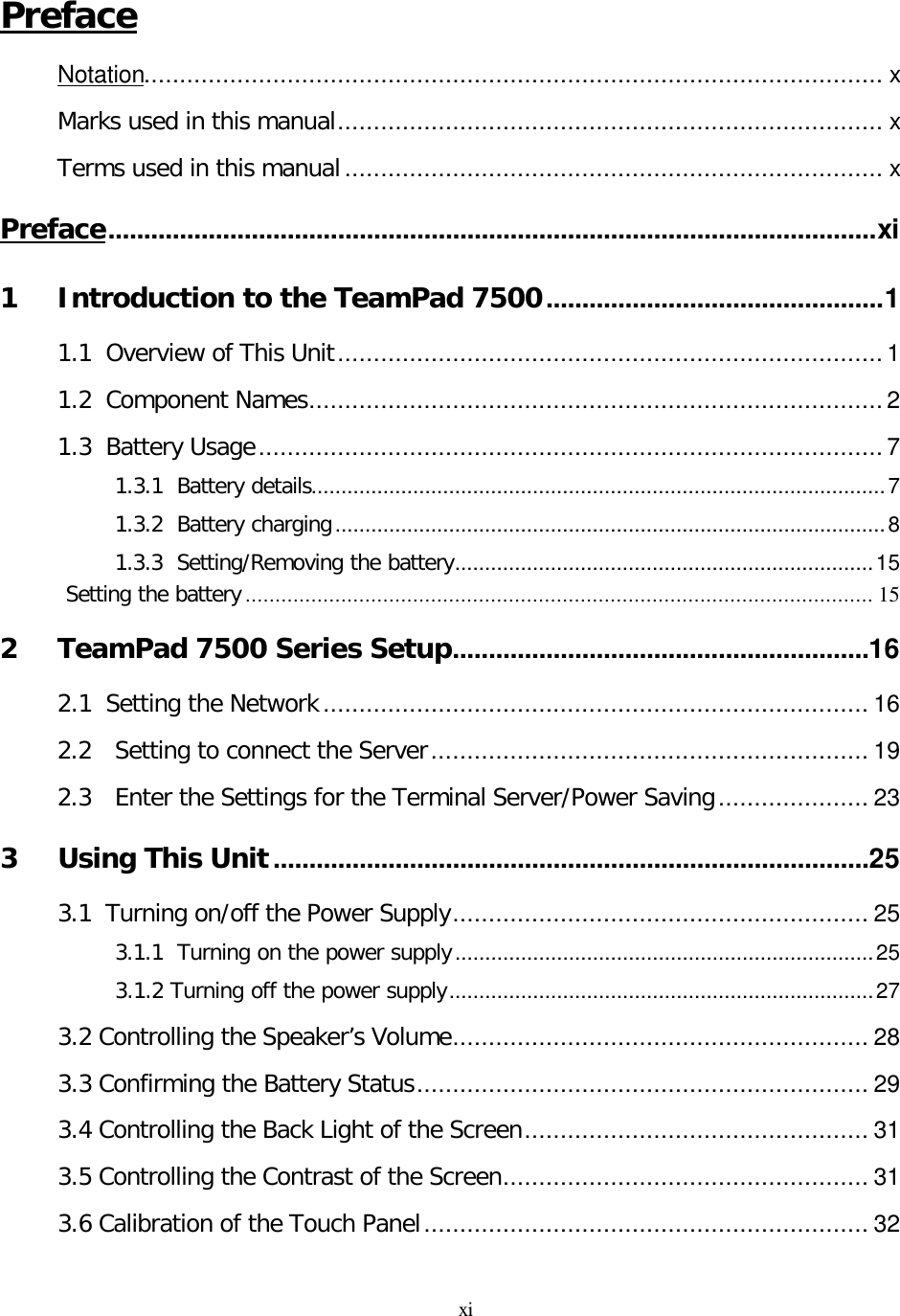
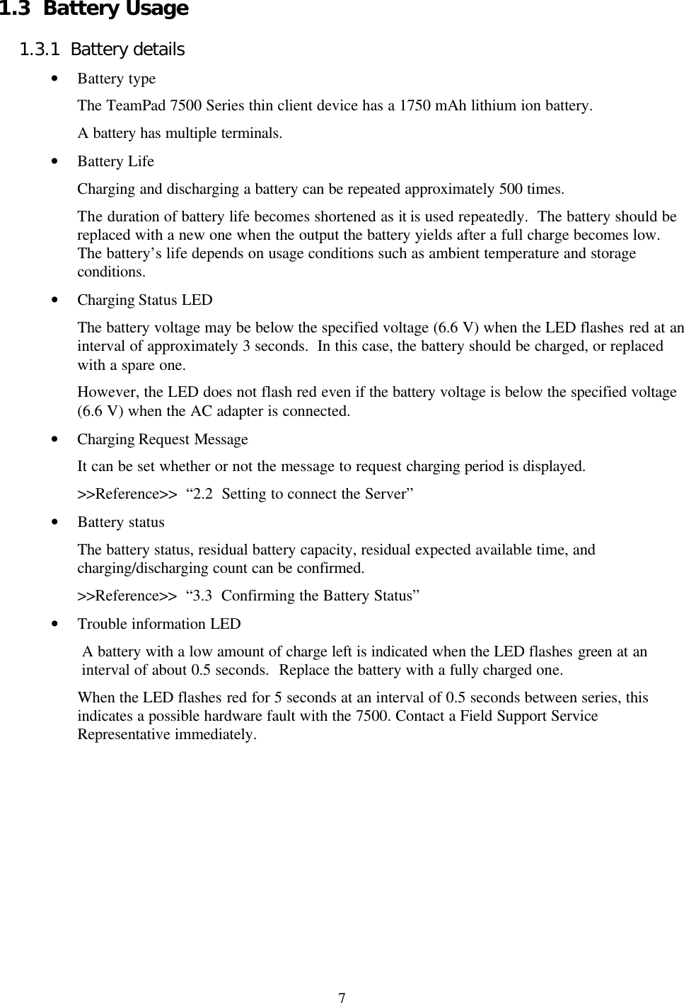
![2 1.2 Component Names [Front] No. Component name Remarks 1 Radio antenna Built-in 2 Battery case The case that holds the battery. 3 Speaker Built-in 4 LCD touch panel Hereafter called “touch panel” or “screen”. [Bottom] No. Component name Remarks 1 AC adapter connector Connector for the AC adapter 2 Charging terminal Terminal connected to the charging adapter 1 2 4 3 2 1](https://usermanual.wiki/Cisco-Systems/102040.Revised-Manual/User-Guide-163953-Page-15.png)
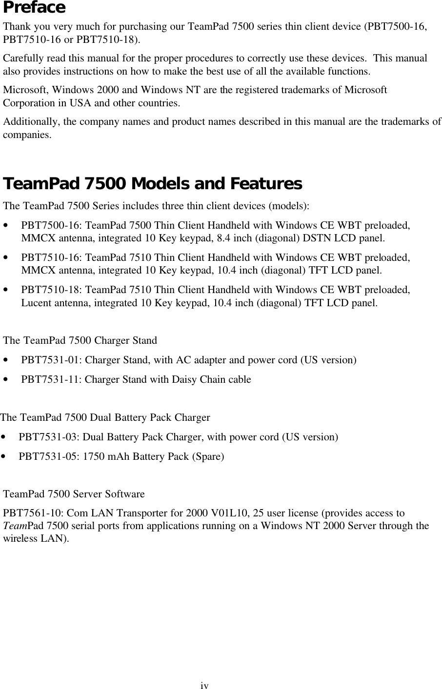
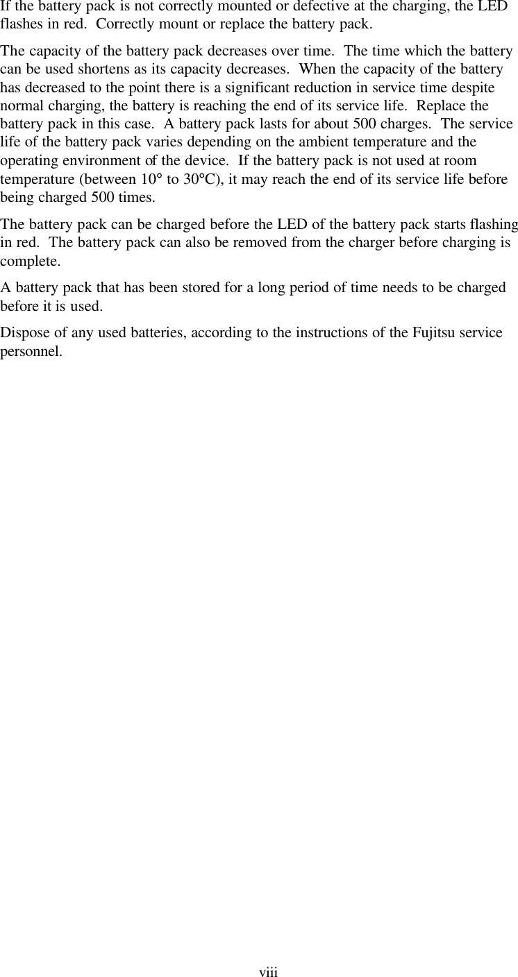
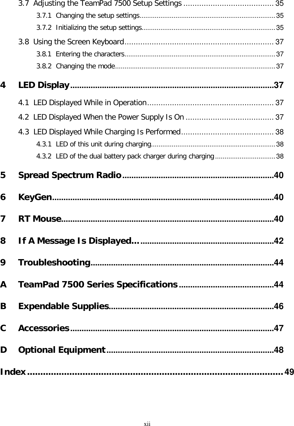
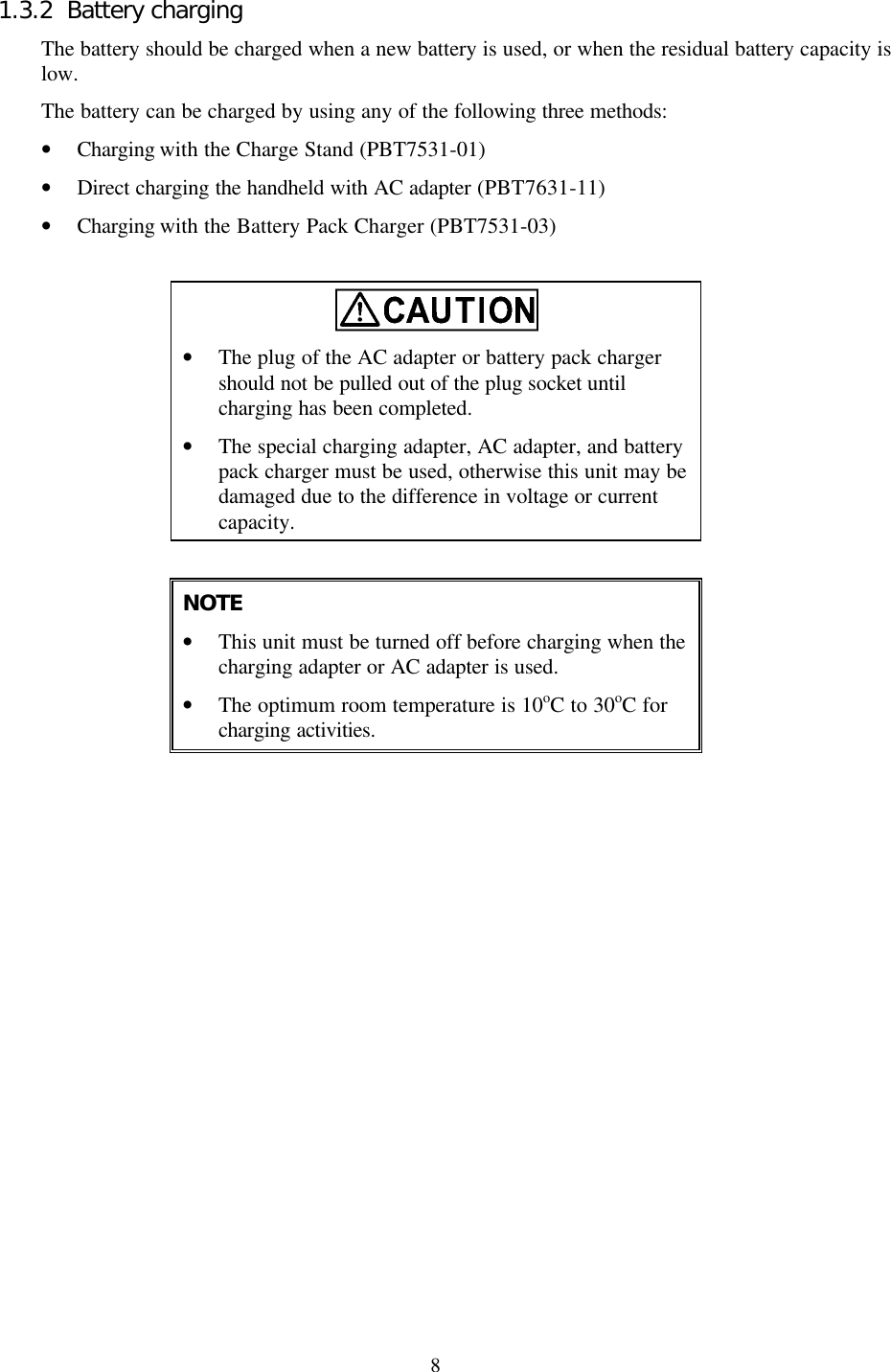
![3 [Back] PBT7500-16 [Back] PBT7510-16 & PBT7510-18 1 2 4 5 6 7 8 10 9 13 11 22 44 88 1010 99 55 66 77 33 1111 1212 1313](https://usermanual.wiki/Cisco-Systems/102040.Revised-Manual/User-Guide-163953-Page-16.png)
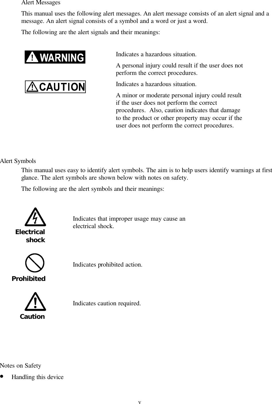
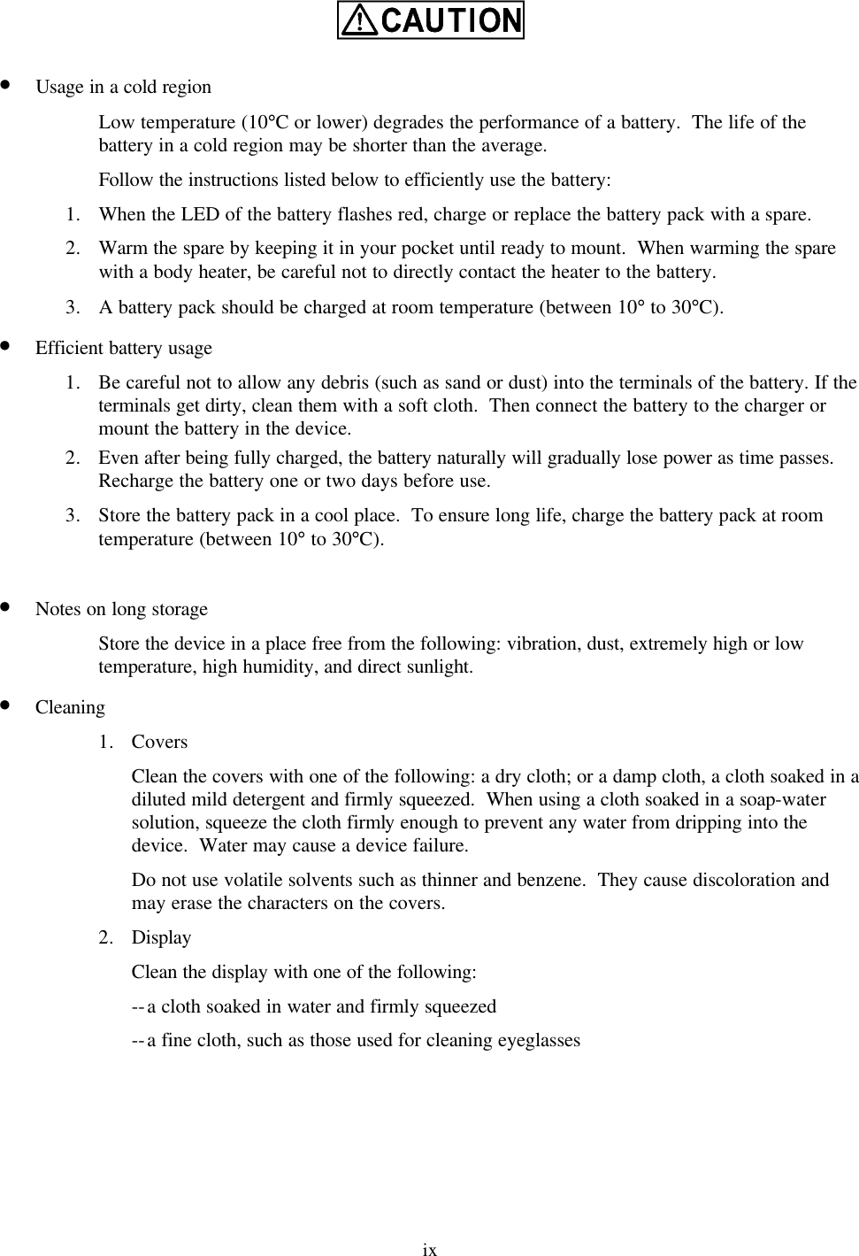
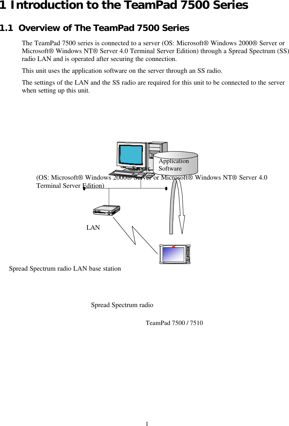
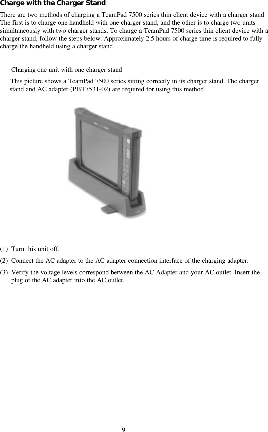
![5 [Keys] No. Component name Remarks 1 Power/Charging status LED LED for displaying the power supply and charging status. Hereafter called “LED”. 2 Ten key 3 Cursor key 4 Clear key 5 Backspace key 6 System key Hereafter called the [SYS] key. 7 Power key For turning on/off the power supply. Hereafter called the [PWR] key. 8 Enter key Hereafter called the [ENT] key. 9 Decimal Point key 10 Function key Hereafter called the [FUNC] key. 11 Back light key For controlling the brightness of the back light on the screen. Hereafter called the [R] key. 12 Contrast key For controlling the contrast of the screen. Hereafter called the [+] key or the [-] key. The keyboard layout was designed with the intention that this unit can be held in a variety of comfortable ways and with the keyboard operating with the thumb of the user's right hand. The following figures demonstrate comfortable ways of holding and operating the 7500. 2 1 3 4 5 6 7 8 9 10 11 12](https://usermanual.wiki/Cisco-Systems/102040.Revised-Manual/User-Guide-163953-Page-18.png)

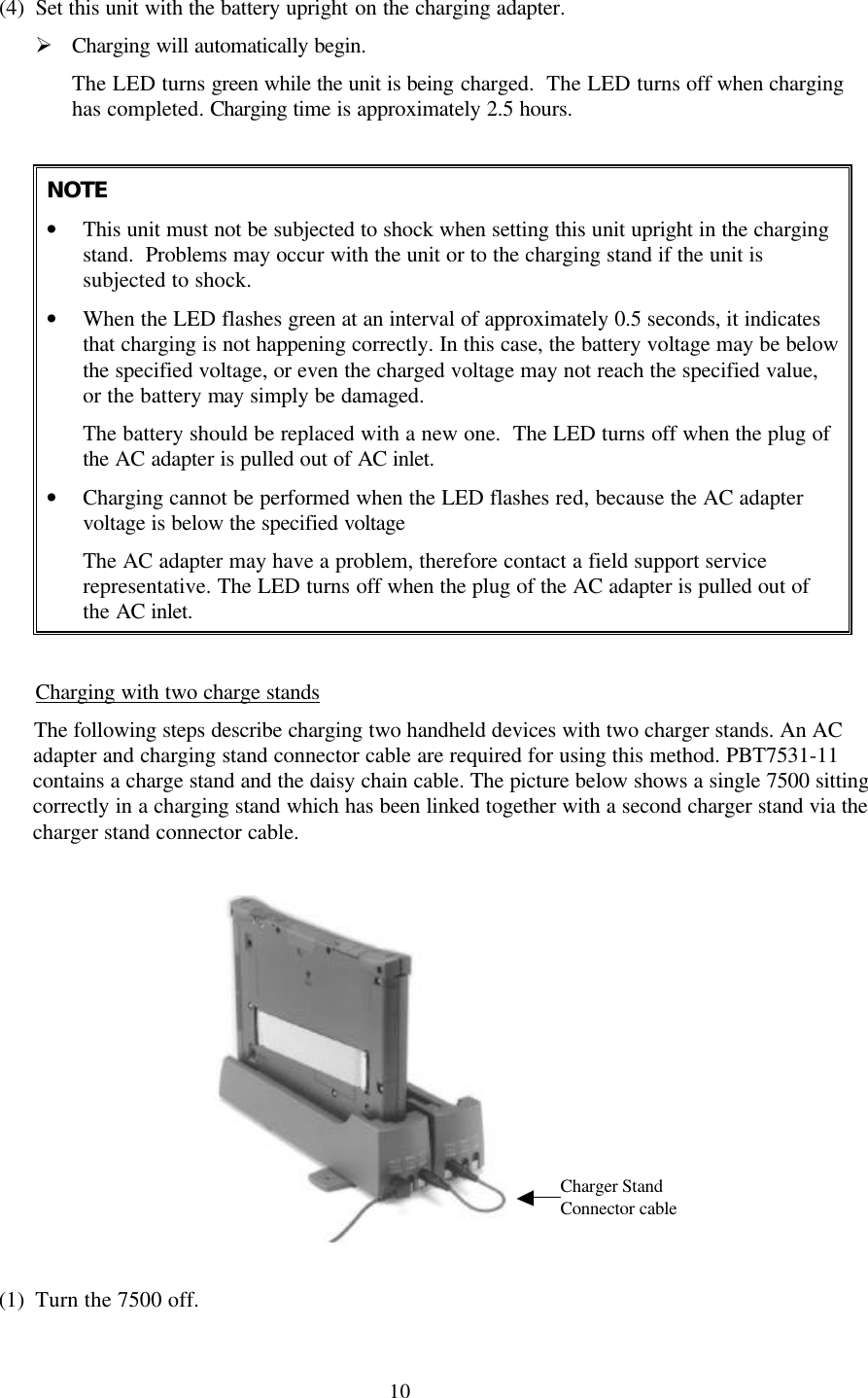
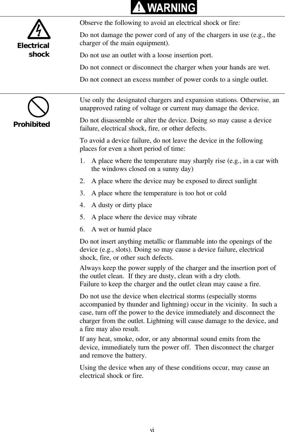
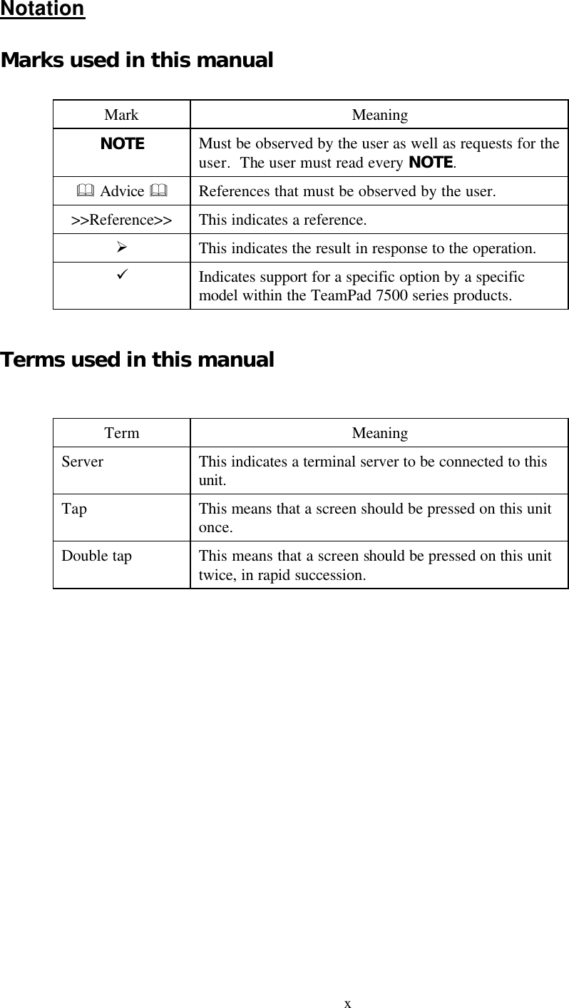
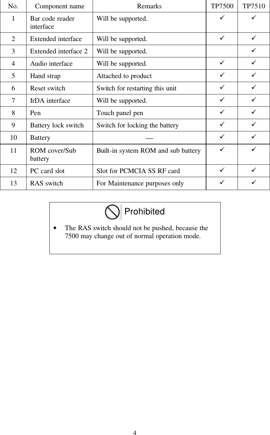
![15 1.3.3 Setting/Removing the battery Setting the battery (1) Two battery lock switches reside on the back surface of the 7500 series device. Slide the battery lock switches to the [UNLOCK] position. (2) Insert the battery correctly into the handheld until a “click” is heard. (3) Slide the battery lock switches to the [LOCK] position. (4) Reverse these steps to insert a new or fully charged battery into the handheld. NOTE The power supply will turn on when the battery lock switches are set to the [LOCK] position. Upper battery lock switch Downward to UNLOCK Insert the battery Lower battery lock switch ULOCK](https://usermanual.wiki/Cisco-Systems/102040.Revised-Manual/User-Guide-163953-Page-28.png)
![16 2 TeamPad 7500 Series Setup Correct setup of the TeamPad 7500 series device consists of the following tasks: Network Settings Change network settings and Spread Spectrum radio settings. Server Settings Set connect entry to server. Terminal Server/Power Saving Settings Set power saving and auto-connect to server settings. NOTE Before setup can begin, please charge the battery and insert it into the handheld. For more information, please refer to: 1.3 Battery Usage >>Reference>> “3.7 Adjusting the TeamPad 7500 Setup Settings” when it is set up again. 2.1 Setting the Network (1) Turn this unit on by pressing the PWR key until LED flashes bright green (about 1 second). Ø This unit will boot up, and the [Change Settings] window for network settings will be displayed. NOTE This battery might be damaged if the LED flashes green for 5 seconds at an interval of](https://usermanual.wiki/Cisco-Systems/102040.Revised-Manual/User-Guide-163953-Page-29.png)
![17 about 0.5 seconds. Replace with a new battery. There might be a hardware fault if the LED flashes red for 5 seconds at an interval of about 0.5 seconds. Contact a field support service representative. (2) Tap on the [Yes] button on the [Change Settings] window for network settings. Ø The screen keyboard and control panel are displayed. >>Reference>> “3.8 Using the Screen Keyboard” for more information on the screen keyboard. & Advice & Tap on the [No] button to set the terminal server/power saving without changing the network settings when this unit is set up again. By tapping on the [No] button, the screen keyboard and the [Power savings and connecting to Terminal Server] window is displayed. >>Reference>> “2.2 Setting to connect the Server” about the [Change setting] window for network settings. (3) Double-tap on the [Network] icon on the control panel. Ø The [Network] window is displayed. (4) Set the items on the [Network] window according to the explanation displayed on the [Network] window. Tap on the [OK] button after the setting has been terminated. Ø The [Network] window is closed. NOTE Ignore the following message displayed, and tap on the [OK] button: “The new setting becomes valid when the adapter is used the next time. The new setting becomes valid by reinserting the adapter into the device after taking it out of the device if the adapter has been Inserted into the device.” NOTE If using a Symbol Spectrum24 card, refer the following action. If using another vender’s RF card, please refer to that specific setup instruction for that vender's RF card. (5) Double-tap on the [Spectrum24 Settings] icon on the control panel to change the SS radio setting. Ø The [Spectrum24 Settings] window is displayed. (6) Set the items on the [Spectrum24 Settings] window. Tap on the [OK] button after the setting has been terminated.](https://usermanual.wiki/Cisco-Systems/102040.Revised-Manual/User-Guide-163953-Page-30.png)
![18 NOTE Contact a network system administrator to confirm the settings of items on the [Spectrum24 Settings] window. Ø The [Spectrum24 Settings] window is closed. (7) Tap on [Close] from the [File] menu on the control panel. Ø After the control panel is closed, the [Power savings and connecting to Terminal Server] window is displayed.](https://usermanual.wiki/Cisco-Systems/102040.Revised-Manual/User-Guide-163953-Page-31.png)
![19 2.2 Setting to connect the Server >>Reference>> “3.8 Using the Screen Keyboard” for more information on about the screen keyboard. (1) Tap on the [Yes] tab on the [Change settings] window. Ø The [WTS Connection Wizard] window is displayed. & Advice & Tap on the [No] tab, don’t change WTS connection settings to change settings of this unit. Tap on the [No] tab, display the [Setting the Terminal Server/Power Saving] window. >>Reference>> “2.3 Enter the Settings for the Terminal Server/Power Saving” to display the “Setting the Terminal Server/Power Saving” window. (2) Set the following settings with the 1st “WTS Connection Wizard” windows.](https://usermanual.wiki/Cisco-Systems/102040.Revised-Manual/User-Guide-163953-Page-32.png)
![20 [Name] entry field Input “fht”. (Fixed) [Server] entry field Input the server’s IP address. [Low Speed Connection] check box Don’t use “Low Speed Connection”. Don’t check this check box. & Advice & Following items is the tab which mean the “WTS connection wizard” window. [Back] bottom Back 1 window to display the “WTS connection wizard” window. [Next] bottom Forward 1window to display the “WTS connection wizard” window. [Cancel] bottom Cancel all settings with the “WTS connection wizard” windows, and display the “Setting the Terminal Server/Power Saving” window. >>Reference>> “2.3 Enter the Settings for the Terminal Server/Power Saving” to display the “Setting the Terminal Server/Power Saving” window. (3) Tap on the [Next] tab. Ø Display the 2nd [WTS Connection Wizard] window.](https://usermanual.wiki/Cisco-Systems/102040.Revised-Manual/User-Guide-163953-Page-33.png)
![21 Ø (4) Set the following settings on the 2nd [WTS Connection Wizard] window. • [Automatic Connection To Server] check box This check box sets whether or not this unit is automatically connected to the server when this unit is turned on. NOTE Don’t uncheck this checked box, the user name, password, and the domain name must be entered by pressing the Ten key when this unit is connected to the server. >>Reference>> “3.1.1 Turning on the power supply ” Usually, you can check off [Automatic Connection To Server] this check box. • [Username] entry field Enter this field when [Automatic Connection To Server] check box. Enter the username to connect the server automatically. [Password] entry field Enter this field when [Automatic Connection To Server] check box. Enter the password to connect the server automatically. Enter the same password to entry the server in [Password] entry field. When the [Password] entry field over flow at the server, an error has occurred at the end of [WTS Connection Wizard]. At this time, enter the correct [Password] entry field. [Domain] entry field Enter this field when [Automatic Connection To Server] check box. Enter the domain to connect the server automatically. (5) Tap on the [Next] tab. Ø Display the 3rd [WTS Connection Wizard] window.](https://usermanual.wiki/Cisco-Systems/102040.Revised-Manual/User-Guide-163953-Page-34.png)
![22 (6) Set the following settings on the 3rd [WTS Connection Wizard] window. [Desktop] Select [Desktop] when an application software is not started just after connecting to the server. [Application File Name] Select [Application File Name] when an optional application software is started just after connecting to the server. Enter the file name of the application software to be started to the lower entry field, starting with the drive name. [Work Directory] entry field The [Work Directory] entry field becomes valid when [Application File Name] is selected in [Program Started When Connecting To Server]. (7) Tap on the [Next] tab. Ø Display the 4th [WTS Connection Wizard] window and display the connection entry to set this time. Don’t tap on the [Next] tab at the 3rd [WTS Connection Wizard] window, make sure to set the [Application File Name] and [Work Directory]. (8) Tap on the [Finish] tab on the 4th [WTS Connection Wizard] window.](https://usermanual.wiki/Cisco-Systems/102040.Revised-Manual/User-Guide-163953-Page-35.png)
![23 Ø Close the [WTS connection wizard] window, and display the [Setting the Terminal Server/Power Saving] window. Ö This is the end of operation to set connection the server. Refer back to “2.3 Enter the Settings for the Terminal Server/Power Saving” for more information on this process. 2.3 Enter the Settings for the Terminal Server/Power Saving >>Reference>> “3.8 Using the Screen Keyboard” for more information about the screen keyboard (1) Tap on the [Power saving] tab on the [Power savings and connecting to Terminal Server] window. (2) Set the following with the [Power savings] tab: • [Default brightness of back light] Select the brightness of the back light when the power supply of this unit is turned on, from the list box. • [Auto back light off timer] Select the time between the no-operation time and the automatic set to the darkest setting of this unit from the list box. Select [Inhibit] if the back light is not set to the darkest setting automatically. • [Auto power off timer] Select the time between the no-operation time and the automatic power-off of this unit from the list box. Select [Inhibit] if the power supply of this unit is set to not automatically turn off. • [Battery low message] Click off the check box to display the message when the residual battery capacity has reached a low amount.](https://usermanual.wiki/Cisco-Systems/102040.Revised-Manual/User-Guide-163953-Page-36.png)
![24 (3) Tap on the [Server connection] tab. (4) Set the following with the [Server connection] tab: • [Auto Connect to a server] Click off the [Enable] check box to connect server automatically when terminal is turned on. & Advice & If [Enable] check box is not checked off, the [Terminal Server client] window will be displayed when terminal is turned on. It can control server connection with using [Terminal Server Client] windows. The server name on [Terminal Server client] windows will be set with the value is configured on [Server] entry field of [WTS wizard] as default. >>Reference>> Please refer to “3.1.1 Turning on the Power Supply” about [Terminal Server Client] Please check this check box normally. (5) Tap on the [OK] button on the [Power savings and connecting to Terminal Server] window. Ø The [Save Settings] window is displayed.](https://usermanual.wiki/Cisco-Systems/102040.Revised-Manual/User-Guide-163953-Page-37.png)
![25 & Advice & The [Initialize] tab is used for initializing the setup settings. >>Reference>> “3.7.2 Initializing the setup settings” (6) Tap on the [Yes] button on the [Save Settings] window. Tap on the [No] button to terminate the setup without saving any information that has been set during the setup. Ø The information set during the setup is not saved, and the power supply of this unit is automatically turned off if the [Yes] button has been tapped. NOTE It takes a few seconds for the power supply of this unit to be automatically turned off. The [PWR] key must not be pressed before the unit powers off automatically. 3 Using The TeamPad 7500 Series Units 3.1 Turning on/off the Power Supply 3.1.1 Turning on the power supply (1) Press the PWR key while the power supply is being turned off. Ø The power supply is turned on. The LED is lit in green while the screen is not displayed. NOTE • There might be a possible hardware fault if the LED flashes red for 5 seconds at an interval of about 0.5 seconds. Contact a field support service representative. • The [Change setting] window for network settings is displayed by pressing the [PWR] key when this unit has not set up, or when the setup settings have been initialized. Press the [PWR] key again after performing the setup. >>Reference>> “2 TeamPad 7500 Setup” about the setup. & Advice & This unit will automatically attempt to connect to the server by turning on the power](https://usermanual.wiki/Cisco-Systems/102040.Revised-Manual/User-Guide-163953-Page-38.png)
![26 supply of this unit when the automatic connection to the server is set during the setup. Enter the IP address of the server in the [Terminal Server Client] window. To display this window press the Ten key when turning on this unit if the automatic connection to the server has not been set during the initial setup. >>Reference>> “2.3 Enter the Settings for the Terminal Server/Power Saving” about the automatic connection to the server.](https://usermanual.wiki/Cisco-Systems/102040.Revised-Manual/User-Guide-163953-Page-39.png)
![27 3.1.2 Turning off the power supply (1) Execute any of the following operations: • Terminate any application software currently running. • Press and hold the [PWR] key (for about 3 seconds) until the power supply has turned off, if the application software is not starting. Ø The power supply is turned off. Perform the operation (2) continuously if the power supply is not turned off after terminating the application software. (2) Execute any of the following operations if the power supply is not turned off even by executing the operation (1): • Tap on the [Power Off] button if the [Reconnect to the Terminal Server] window is displayed. • Press and hold the [PWR] key (for about 3 seconds) until the power supply is turned off if the [Reconnect to the Terminal Server] window is not displayed. Ø The power supply is turned off.](https://usermanual.wiki/Cisco-Systems/102040.Revised-Manual/User-Guide-163953-Page-40.png)
![28 3.2 Controlling the Speaker’s Volume The following describes the operation to control the speaker’s volume. NOTE The volume is automatically set to [High] when this unit has been restarted using the Reset switch, or when the battery has been replaced with a new one. Adjust the speaker’s volume if necessary. (1) Press the [R] key by holding on the [SYS] key while the power supply is being turned on. Ø The [Volume and Battery] window will be displayed. >>Reference>> “3.3 Confirming the Battery Status” for battery information. (2) Select the speaker’s volume from [Volume]. (3) Tap on the [OK] button.](https://usermanual.wiki/Cisco-Systems/102040.Revised-Manual/User-Guide-163953-Page-41.png)
![29 3.3 Confirming the Battery Status The following describes the operation to confirm the battery status, residual battery capacity, residual expected available time, and charging/discharging count. (1) Press the [R] key by holding on the [SYS] key while the power supply is being turned on. Ø The [Volume and Battery] window is displayed. >>Reference>> “3.2 Controlling the Speaker’s Volume” for adjusting the speaker’s volume. (2) Confirm the battery status by using [Battery]. The items in [Battery] have the following meanings: • Status The battery status is displayed as [Normal], [Insufficient Residual Capacity], [Abnormal], or [Undetermined]. NOTE • The battery capacity is insufficient if [Insufficient Residual Capacity] is displayed. Charge the battery, or replace it with a spare battery. • The battery is abnormal if [Abnormal] is displayed. Replace it with a spare battery. • Please press the [R] key by holding on the [SYS] key again. The battery or this unit is abnormal if [Undetermined] is displayed after few times pressing the [R] key by holding on the [SYS]. Please contact field support service.](https://usermanual.wiki/Cisco-Systems/102040.Revised-Manual/User-Guide-163953-Page-42.png)
![30 • Residual battery capacity The residual battery capacity is displayed with %. However, [Undetermined] will be displayed in [Residual Battery Capacity] if [Undetermined] is displayed in [Status]. • Residual expected available time The residual expected available time for the battery is displayed in the unit of minutes. However, [Undetermined] will be displayed in [Residual Expected Available Time] if [Undetermined] is displayed in [Status]. • Charging/discharging count The charging/discharging count where the battery was repeated in the past is displayed. However, [Undetermined] will be displayed in [Number of Charging/Discharging periods] if [Undetermined] is displayed in [Status]. (3) Tap on the [OK] button.](https://usermanual.wiki/Cisco-Systems/102040.Revised-Manual/User-Guide-163953-Page-43.png)
![31 3.4 Controlling the LCD Panel Back Light The following describes the operation to control the LCD panel back light. >>Reference>> “2.2 Setting to connect the Server” about setting the back light brightness when turning on the power supply. (1) Press the [R] key while the power supply is being turned on. Ø Each time the [R] key is pressed, the brightness of the back light is changed as follows: Dark Slightly dark Slightly bright Bright 3.5 Controlling the Contrast of the LCD Panel The following describes the operation to control the contrast of the LCD panel. (1) Press the [+] key or [-] key while the power supply is being turned on. Ø The darkness of the screen is increased each time the [+] key is pressed. The brightness of the screen is increased each time the [-] key is pressed.](https://usermanual.wiki/Cisco-Systems/102040.Revised-Manual/User-Guide-163953-Page-44.png)
![32 3.6 Calibration of the LCD Touch Panel The LCD touch panel has lost calibration accuracy if the touch panel does not respond when tapping on the screen, or if a different portion of the touch screen is activated other than the part which received the input. In this case, the operation to correct the inaccuracy of the touch panel should be executed. This operation is called “Touch Panel Calibration”. There is no need to perform this calibration when this unit is purchased, because the touch panel has been calibrated. NOTE • The [PWR] key must not be pressed while the touch panel calibration tool is running. The touch panel calibration would then need be re-executed because the setting of touch panel calibration becomes invalid if the [PWR] key is pressed. • The touch panel calibration must be executed using a fully-charged battery or using the AC adapter connected to the unit. The setup settings are initialized if the battery capacity has become insufficient during the touch panel calibration. • If battery charge become low during the touch panel calibration, replace the battery, then re-execute the touch panel calibration. (1) Press the [PWR] key by holding on the [SYS] key while the power supply of this unit is being turned off. Ø The touch panel calibration screen is displayed. (2) Tap on the [+] mark displayed on the touch panel calibration screen with a stylus. Tap on the [Cancel] button to stop the touch panel calibration. NOTE The tapped [+] does not disappear if the tapped position is about 1 cm distant from the](https://usermanual.wiki/Cisco-Systems/102040.Revised-Manual/User-Guide-163953-Page-45.png)
![33 center of [+]. In this case, tap on the [+] mark again. & Advice & The touch panel calibration can be stopped by pressing the [ENT] key if the [Cancel] button is not valid. Ø The tapped [+] disappears, and another [+] is displayed at a different position. However, the touch panel calibration will stop, and the unit will restart if the [Cancel] button is tapped. (3) Tap on [+] with a pen. Five [+] symbols are sequentially displayed. Tap on these five symbols with a pen in the order indicated on the display. Ø The touch panel calibration completion window is displayed by tapping on the fifth [+] symbol. (4) Tap on the [OK] button on the message window. & Advice & The touch panel calibration can be terminated by pressing the [ENT] key if the [OK] button is invalid. Ø This unit is restarted. % Request % • The setup settings are initialized if the battery becomes insufficient from when the [OK] button is tapped until this unit is restarted. Perform the setup functions again.](https://usermanual.wiki/Cisco-Systems/102040.Revised-Manual/User-Guide-163953-Page-46.png)
![34 • It takes a few seconds for this unit to be restarted after tapping on the [OK] button. The [PWR] key must not be pressed before this unit is restarted.](https://usermanual.wiki/Cisco-Systems/102040.Revised-Manual/User-Guide-163953-Page-47.png)
![35 3.7 Adjusting the TeamPad 7500 Setup Settings 3.7.1 Changing the setup settings The following describes the operation to change the setup settings. (1) Press the [PWR] key while holding down the [FUNC] key, [SYS] key, and an optional location on the touch panel when the power supply of the unit is being turned off. Ø This unit is started, and the [Change setting] window for network settings is displayed. (2) Change the setup settings according to your needs. >>Reference>> From the operation (2) in “2.1 Setting the Network” to “2.3 Enter the Settings for the Terminal Server/Power Saving” about the setup settings. 3.7.2 Initializing the setup settings The following describes the operation to initialize the setup settings to the mode when this unit is purchased. & Advice & • The [Change setting] window for network settings is displayed by turning on this unit after initializing the setup settings. Set the network. • The touch panel calibration mode is not initialized even if the setup settings are initialized. (1) Press the [PWR] key while holding on the [FUNC] key, [SYS] key, and an optional location on the touch panel when the power supply of this unit is being turned off. Ø This unit is started, and the [Change setting] window for network settings is displayed. (2) Tap on the [No] button on the [Change setting] window for network settings. Ø The screen keyboard and [Power savings and connecting to Terminal Server] window is displayed. (3) Click on the [Initialize] tab on the [Power savings and connecting to Terminal Server] window. (4) Click off the [Initialize] check box in the [Initialize] tab.](https://usermanual.wiki/Cisco-Systems/102040.Revised-Manual/User-Guide-163953-Page-48.png)
![36 (5) Tap on the [OK] button on the [Power savings and connecting to Terminal Server] window. Ø The [Save Settings] window is displayed. (6) Tap on the [Yes] button on the [Save Settings] window. However, if the setup settings are not initialized, then tap on the [No] button. Ø The setup settings are initialized, and the power supply of this unit is automatically turned off if the [Yes] button has been tapped. The setup settings are not initialized, and the power supply of this unit is automatically turned off if the [No] button has been tapped.](https://usermanual.wiki/Cisco-Systems/102040.Revised-Manual/User-Guide-163953-Page-49.png)
![37 3.8 Using the Screen Keyboard The screen keyboard is a full alphanumeric keyboard which can be accessed by pressing the [SYS] and [DOWN ARROW]. 3.8.1 Entering the characters (1) Tap on a key on the screen keyboard. Ø The character is entered. 3.8.2 Changing the mode The screen keyboard has two modes, i.e., alphabetical lowercase character mode and alphabetical uppercase character mode. The screen keyboard is displayed in alphabetical lowercase character mode. (1) Tap on the [CAP] key on the screen keyboard while the screen keyboard is being displayed. Ø The alphabetical lowercase character mode and alphabetical uppercase character mode are switched alternately each time the [CAP] key is tapped. 4 LED Display The following explains the action to be taken when the LED is lit or flashes. 4.1 LED Displayed While in Operation Take action according to the following “Response” if the LED blinks during operation: LED display Response Color Display status Red Flash (at an interval of about 3 seconds) The battery voltage is below the specified voltage. Charge the battery, or replace the battery with a spare battery. However, the LED does not blink when this unit is connected to the AC adapter, even if the battery voltage is below the specified voltage. 4.2 LED Displayed When the Power Supply Is On Take action according to the following “Response” if the LED is lit or flashes when the power supply is turned on:](https://usermanual.wiki/Cisco-Systems/102040.Revised-Manual/User-Guide-163953-Page-50.png)
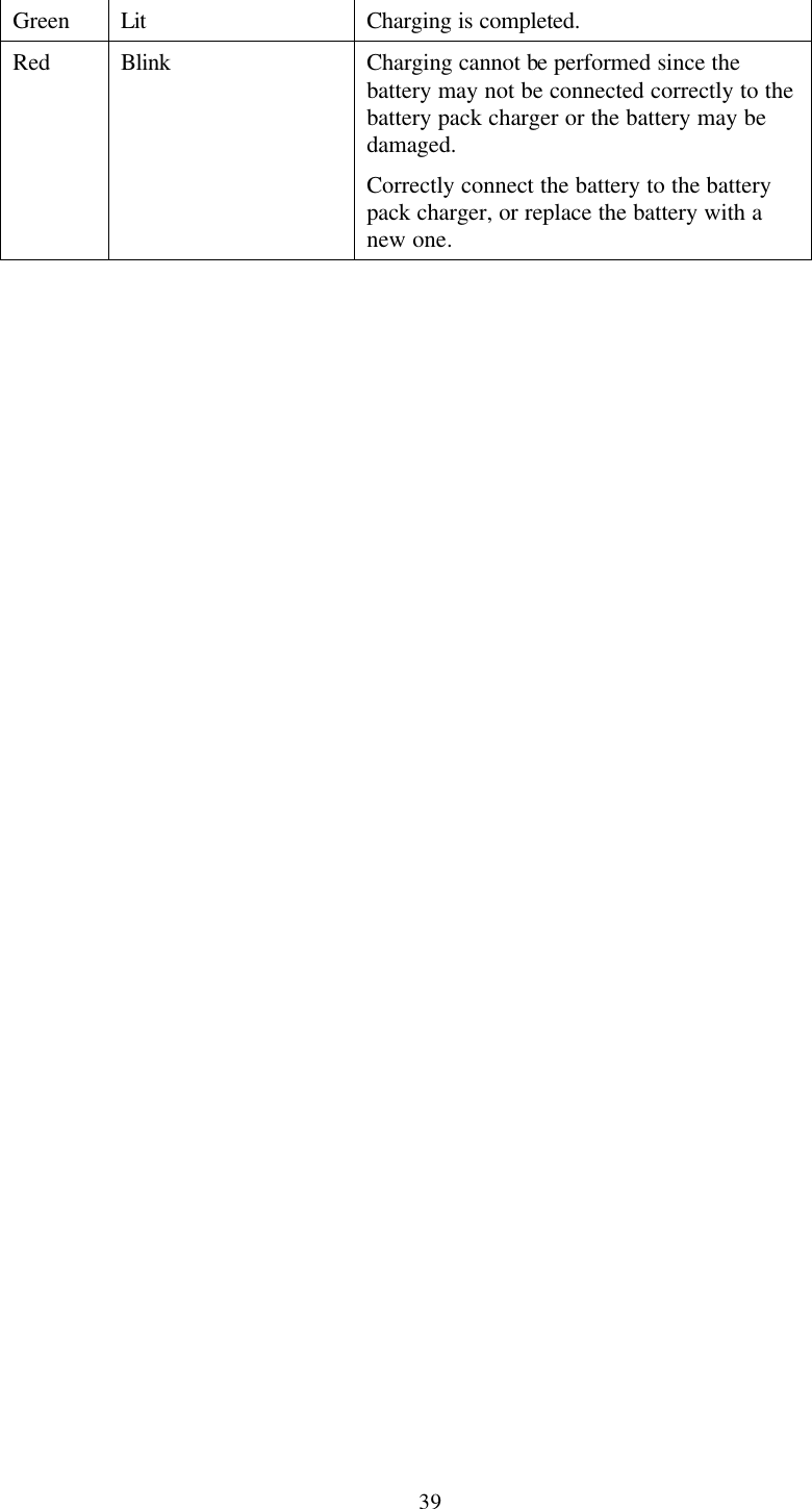
![38 LED display Response Color Display status Green Fully Lit This unit has initiated the boot up process. The LED is lit when the [PWR] key is pressed until the screen is displayed. Red Blink (for 5 seconds at an interval of about 0.5 seconds) This unit is abnormal. Contact a Field support service representative. 4.3 LED Displayed While Charging Is Performed 4.3.1 LED of this unit during charging Take action according to the following “Response” if the LED of this unit is lit or flashes while charging is being performed: LED display Response Color Display status Green Lit Charging is being performed. The LED switches off after charging is completed Green Flash (at an interval of about 0.5 seconds) Charging is not performing normally. The battery voltage is below the normal voltage range, or the battery voltage has not reached the specified voltage even after charging has completed. Replace the battery with a new one. The LED switches off by pulling the plug of the AC adapter out of the plug socket. Red Lit The AC adapter voltage is below the specified voltage , so charging cannot be performed. The AC adapter may have a problem, therefore contact a field support service. The LED switches off by pulling the plug of the AC adapter out of the plug socket. 4.3.2 LED of the dual battery pack charger during charging Take action according to the following “Response” if the LED of the dual battery pack charger is lit or flashes while charging is being performed: LED display Response Color Display status Orange Lit During charging.](https://usermanual.wiki/Cisco-Systems/102040.Revised-Manual/User-Guide-163953-Page-51.png)
![42 8 If A Message Is Displayed... Take action according to the “Response” if any of the following messages are displayed. Message Response The DHCP could not obtain the IP address. Reinsert the card, or allocate the address manually. The DHCP could not obtain the IP address. Verify whether or not the network has been set for the DHCP to obtain the IP address. Contact the network administrator if the problem persists. An error has occurred, therefore stop the touch panel calibration. An error has occurred during the touch panel calibration. Tap on the [OK] button to stop the touch panel calibration, then re-execute the touch panel calibration. >>Reference>> “3.6 Calibration of the Touch Panel” if an error occurs frequently, contact a Field support service representative. The server could not be connected. The connection to the server has failed. Verify the setup settings. >>Reference>> “3.7 Adjusting the TeamPad 7500 Setup Settings” Charge the battery. The residual battery capacity has become insufficient. Charge the battery, or replace the battery with a new one. >>Reference>> “1.3 Battery Usage” An error has been detected in the flash ROM. The set data stored in the flash ROM has been damaged. Set up this unit again. >>Reference>> “3.7 Adjusting the TeamPad 7500 Setup Settings” Contact a Field support service representative if an error occurs frequently. No data can be saved in the flash ROM. No data can be written to the flash ROM. Contact a Field support service. The flash ROM clearing has failed. The flash ROM cannot be cleared. Contact a Field support service. Message Response The radio LAN driver has not been The radio LAN driver has not been installed or has](https://usermanual.wiki/Cisco-Systems/102040.Revised-Manual/User-Guide-163953-Page-55.png)
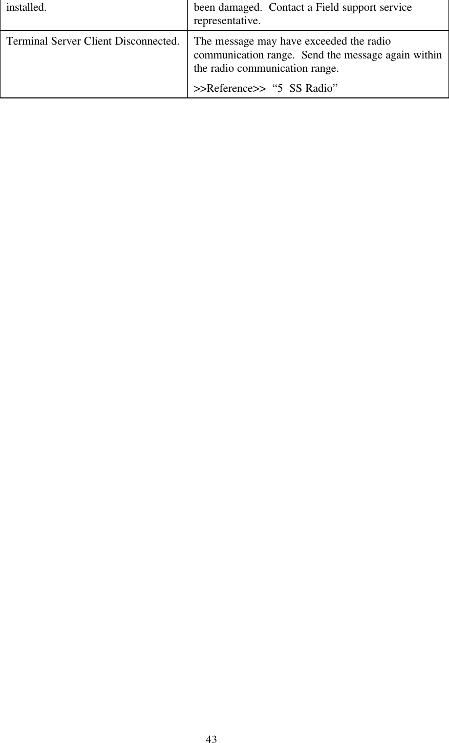
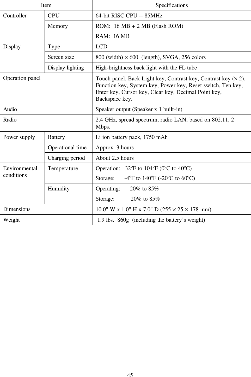
![44 9 Troubleshooting Take action according to “Response” before contacting a Field support service representative if any of the following symptoms has been detected during using this unit. Symptom Response The power supply cannot be turned on. The battery charge may be low. Replace the low capacity battery with a fully charged one. >>Reference>> “1.3 Battery Usage” The battery may have reached the end of its lifecycle. Replace the insufficient battery with a new one. >>Reference>> “1.3 Battery Usage” Make sure the battery has been correctly installed. For example, the battery lock switch might be set to the [UNLOCK] setting. >>Reference>> “1.3.3 Setting/Removing the battery” The screen has either been significantly darkened or brightened, therefore it is hard to see. Control the contrast of the screen. >>Reference>> “3.5 Controlling the Contrast of the Screen” The battery charge may be low. Replace the low capacity battery with a charged one. >>Reference>> “1.3 Battery Usage” The screen is displayed briefly and disappears when the power supply is turned on by pressing the [PWR] key. The battery charge may be low. Replace the battery with a charged one. >>Reference>> “1.3 Battery Usage” No sound is coming from the speaker. The speaker’s volume may be set to [SILENCE]. Verify the speaker’s volume. >>Reference>> “3.2 Controlling the Speaker’s Volume” The touch panel is not valid. The coordinates on the touch panel may have shifted. Execute the touch panel calibration. >>Reference>> “3.6 Calibration of the Touch Panel” Terminal Server Client Disconnected. The message may have exceeded the radio communication range. Send the message again within the radio communication range. >>Reference>> “5 SS Radio” A TeamPad 7500 Specifications](https://usermanual.wiki/Cisco-Systems/102040.Revised-Manual/User-Guide-163953-Page-57.png)