Cisco Systems 102067 4.9GHz Radio Module User Manual 1520higb
Cisco Systems Inc 4.9GHz Radio Module 1520higb
Contents
- 1. Manual 1
- 2. Manual 2
- 3. Manual 3
Manual 2

REVIEW DRAFT—CISCO CONFIDENTIAL
2-21
Cisco Aironet 1520 Series Outdoor Mesh Access Point Hardware Installation Guide
OL-12632-03
Chapter 2 Mounting Instructions
Mounting the Access Point
Mounting the Access Point on a Pole
When installing an access point on a vertical pole, mast, or a streetlight pole, you should use the optional
Cisco pole mount kit. The kit supports metal, wood, or fiberglass poles from 2 to 16 inches in diameter.
Assembling the Pole Clamp Bracket and the Mounting Bracket
When installing an access point on a pole, mast, or a streetlight, you should use the optional Cisco pole
mount kit. The kit supports metal, wood, or fiberglass poles from 2 to 16 inches in diameter.
The pole mount kit contains several parts that you must assembled prior to mounting on a pole. First you
need to assemble two strap brackets on the pole clamp bracket that are positioned for the pole diameter
you are using to mount the access point. Figure 2-9 illustrates the pole diameter indicators and bolt holes
on the pole clamp bracket.
REVIEW DRAFT—CISCO CONFIDENTIAL
2-22
Cisco Aironet 1520 Series Outdoor Mesh Access Point Hardware Installation Guide
OL-12632-03
Chapter 2 Mounting Instructions
Mounting the Access Point
Figure 2-9 Pole Clamp Bracket Adjustment Hole Locations
1Pole size indicators
• 2 to 6 in.
• 6 to 11 in.
• 11 to 16 in.
2Bolt holes for pole diameters
(11 to 16 inches indicated)
REVIEW DRAFT—CISCO CONFIDENTIAL
2-23
Cisco Aironet 1520 Series Outdoor Mesh Access Point Hardware Installation Guide
OL-12632-03
Chapter 2 Mounting Instructions
Mounting the Access Point
To assemble the pole clamp bracket, perform these steps:
Step 1 Position the strap brackets on the pole clamp bracket for the pole diameter you are using and secure each
strap bracket with two M8 x16 bolts (with lock washers) (see Figure 2-10). Tighten the bolts to
13 to 15 ft lbs (17.6 to 20.3 Nm).
Figure 2-10 Assembled Pole Clamp Bracket and Strap Brackets
1M8 x1.25x16 bolts (with lock
washers)
3Strap bracket
(shown positioned for 11 to 16 inch diameter pole)
2Pole clamp bracket

REVIEW DRAFT—CISCO CONFIDENTIAL
2-24
Cisco Aironet 1520 Series Outdoor Mesh Access Point Hardware Installation Guide
OL-12632-03
Chapter 2 Mounting Instructions
Mounting the Access Point
Step 2 Screw the M8 nut onto the pole clamp bracket support bolt, and tighten just enough to prevent the bolt
from falling off.
Step 3 Go to the “Pole Mounting” section on page 2-24.
Pole Mounting
The access point can be installed where power is available, without the need for a wired LAN
connection. The access point uses intelligent wireless routing that is based on the Adaptive Wireless Path
Protocol (AWPP). AWPP enables a remote access point to dynamically optimize the best route to the
wired LAN network using another access point.
The LAP1522 model uses the 5-GHz radio for the Mesh backhaul Mesh connections. The 2.4-GHz radio
is used for local wireless client access. The LAP1521 model uses the 2.4-GHz radio for both Mesh
backhaul and local wireless client access.
To mount your access point on a vertical pole or streetlight pole, you need to install two metal bands
around the pole to support the access point. This process requires extra tools and material not provided
in the pole mount kit (see Table 2-3).
To mount the access point onto a vertical pole or streetlight pole, follow these steps:
Step 1 Select a mounting location on the pole to mount the access point. You can attach the access point to any
pole from 2 to 16 in. (5.1 to 40.6 cm) in diameter.
Note If you will be using a streetlight power tap adapter, position the access point within 3 ft (1 m) of
the outdoor light control.
Step 2 For poles larger than 3.5 in. (8.9 cm), mount the pole clamp bracket assembly to a pole (see Figure 2-11)
using two metal straps. Following the instructions provided with the hand strap tool
(AIR-BAND-INST-TL=), loop each metal strap twice through the slots on the strap bracket.
Caution Do not place the metal straps in the large open area between the pole clamp bracket and the strap
brackets, because this does not properly secure the access point.
Ta b l e 2-3 Material Needed to Mount Access Point on a Pole
Mounting Method Materials Required In Kit
Vertical or streetlight pole Two 0.75-in. (1.9 cm) stainless steel bands
Band hand tool (Cisco AIR-BAND-IT-TOOL=)
Ground lug (provided with access point)
Crimping tool for ground lug, Panduit CT-720 with
CD-720-1 die (http://onlinecatalog.panduit.com)
#6 AWG Ground wire
Yes
No
Yes
No
No
REVIEW DRAFT—CISCO CONFIDENTIAL
2-25
Cisco Aironet 1520 Series Outdoor Mesh Access Point Hardware Installation Guide
OL-12632-03
Chapter 2 Mounting Instructions
Mounting the Access Point
Figure 2-11 Clamp Bracket Assembly Mounted on Poles Larger than 3.5 in. (8.9 cm)
Step 3 For pole diameters of 3.5 in. (8.9 cm) or less, mount the pole clamp bracket assembly to a pole using
two metal straps looped through the space between the pole clamp bracket and the strap brackets (see
Figure 2-12) to provide maximum holding strength for extreme environments. Following the
instructions provided with the hand strap tool (AIR-BAND-INST-TL=), loop each metal strap twice.
1Pole clamp bracket 3Metal mounting strap
2Strap slot in strap bracket 4Pole
REVIEW DRAFT—CISCO CONFIDENTIAL
2-26
Cisco Aironet 1520 Series Outdoor Mesh Access Point Hardware Installation Guide
OL-12632-03
Chapter 2 Mounting Instructions
Mounting the Access Point
Figure 2-12 Metal Strap Open Space for 3.5 in. (8.9 cm) and Smaller Poles
Caution Do not place the metal straps in the large open area between the pole clamp bracket and the strap
brackets, because this does not properly secure the access point.
Step 4 Position the pole clamp bracket on the pole as needed before tightening the metal bands.
Note When the metal bands are tightened to the full tension, the pole clamp bracket cannot be adjusted
unless the metal bands are cut or disassembled.
1Metal strap open space
REVIEW DRAFT—CISCO CONFIDENTIAL
2-27
Cisco Aironet 1520 Series Outdoor Mesh Access Point Hardware Installation Guide
OL-12632-03
Chapter 2 Mounting Instructions
Mounting the Access Point
Step 5 Tighten the metal bands using the band strap tool (Cisco AIR-BAND-IT-TOOL=), following the
operating instructions in the box with the tool. Ensure the metal bands are as tight as possible.
Step 6 Place the mounting bracket onto the pole clamp bracket support bolt (see Figure 2-13).
Step 7 For vertical poles, position the mounting bracket as shown in Figure 2-13. For horizontal streetlight
poles, rotate the mounting bracket 90o from the position shown in Figure 2-13.
Step 8 Install four M8 x16 bolts (with flat and lock washers) into the bolt holes.
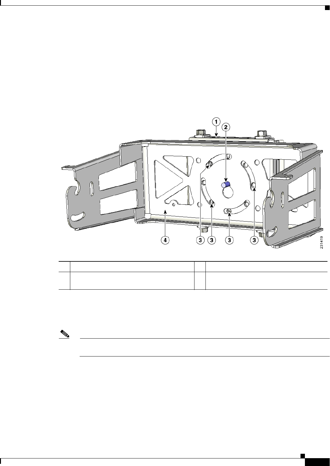
Figure 2-13 Screw Hole Locations on the Mounting Bracket and Pole Clamp Bracket Assembly
Step 9 Hand-tighten the bolts and the nut (do not overtighten).
Step 10 Adjust the top edge of the mounting bracket until it is horizontal and tighten the bolts and the flange nut
(see Figure 2-13) to 13 to 15 ft lbs (17.6 to 20.3 Nm).
Note The mounting bracket can be adjusted up to 45o to compensate for tilted horizontal streetlight
poles.
1Pole clamp bracket assembly 3Bolt holes
2Access point support bolt
(M8 flange nut not shown)
4Mounting bracket
REVIEW DRAFT—CISCO CONFIDENTIAL
2-28
Cisco Aironet 1520 Series Outdoor Mesh Access Point Hardware Installation Guide
OL-12632-03
Chapter 2 Mounting Instructions
Mounting the Access Point
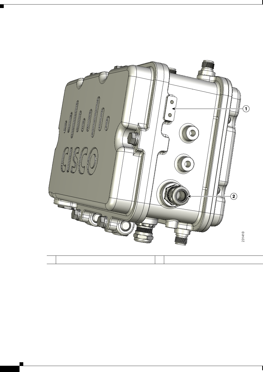
Step 11 Screw a M8 x16 bolt (without a flat or lock washer) in the top support bolt hole on each side the access
point (see Figure 2-14). Do not screw the bolt all the way in. Leave a gap of approximately 0.25 in
(0.635 cm).
Figure 2-14 Location of Access Point Top Support Bolt Hole
1Ground lug screw holes location 3Second bolt hole location
2M8 x16 bolt (without flat or lock washers)
(supplied with pole mount kit)
REVIEW DRAFT—CISCO CONFIDENTIAL
2-29
Cisco Aironet 1520 Series Outdoor Mesh Access Point Hardware Installation Guide
OL-12632-03
Chapter 2 Mounting Instructions
Mounting the Access Point
Step 12 Position the two bolts on the access point into the access point quick-mount notch on the mounting
bracket (see Figure 2-15).
Note The access point should be positioned with the LEDs on the bottom to allow viewing from the
ground and with the hinged cover facing out.
Figure 2-15 Access Point Hanging in Mounting Bracket
Step 13 Screw a M8 x16 bolt (with flat and lock washers) into the second bolt hole on each side of the access
point (see Figure 2-15).
Step 14 Ensure the front of the access point is vertical, and tighten the four bolts to 13 to 15 ft lbs
(17.6 to 20.3 Nm).
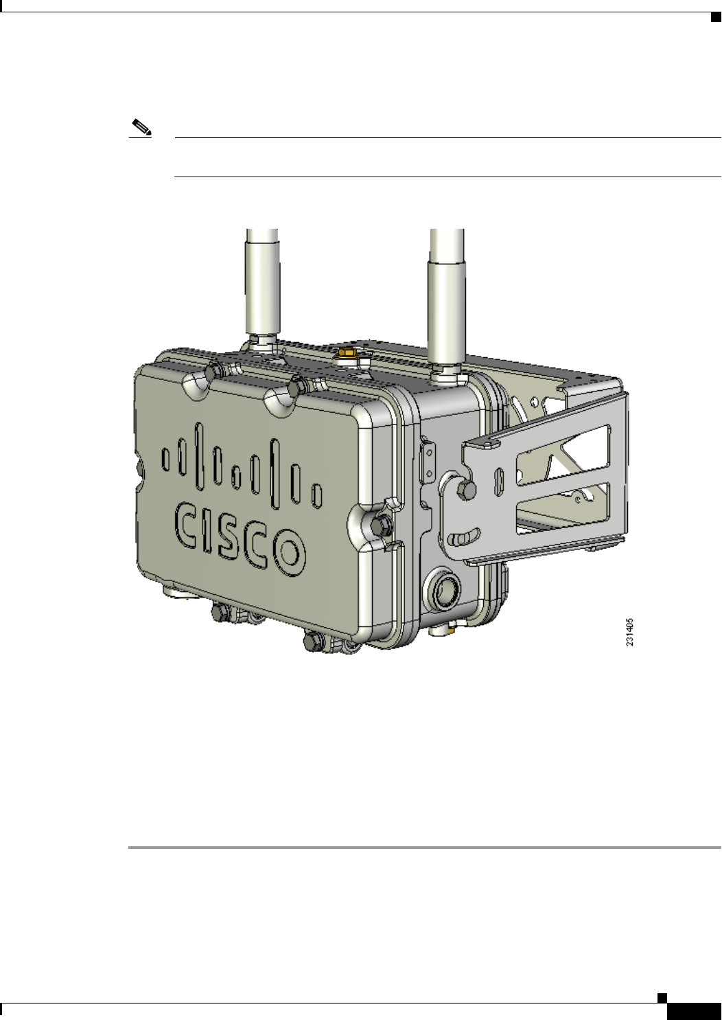
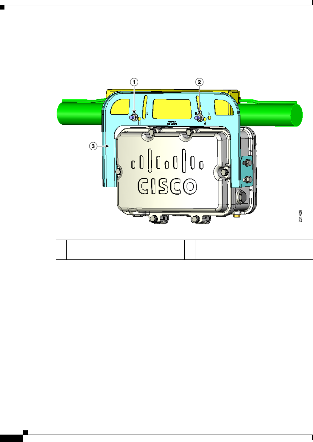
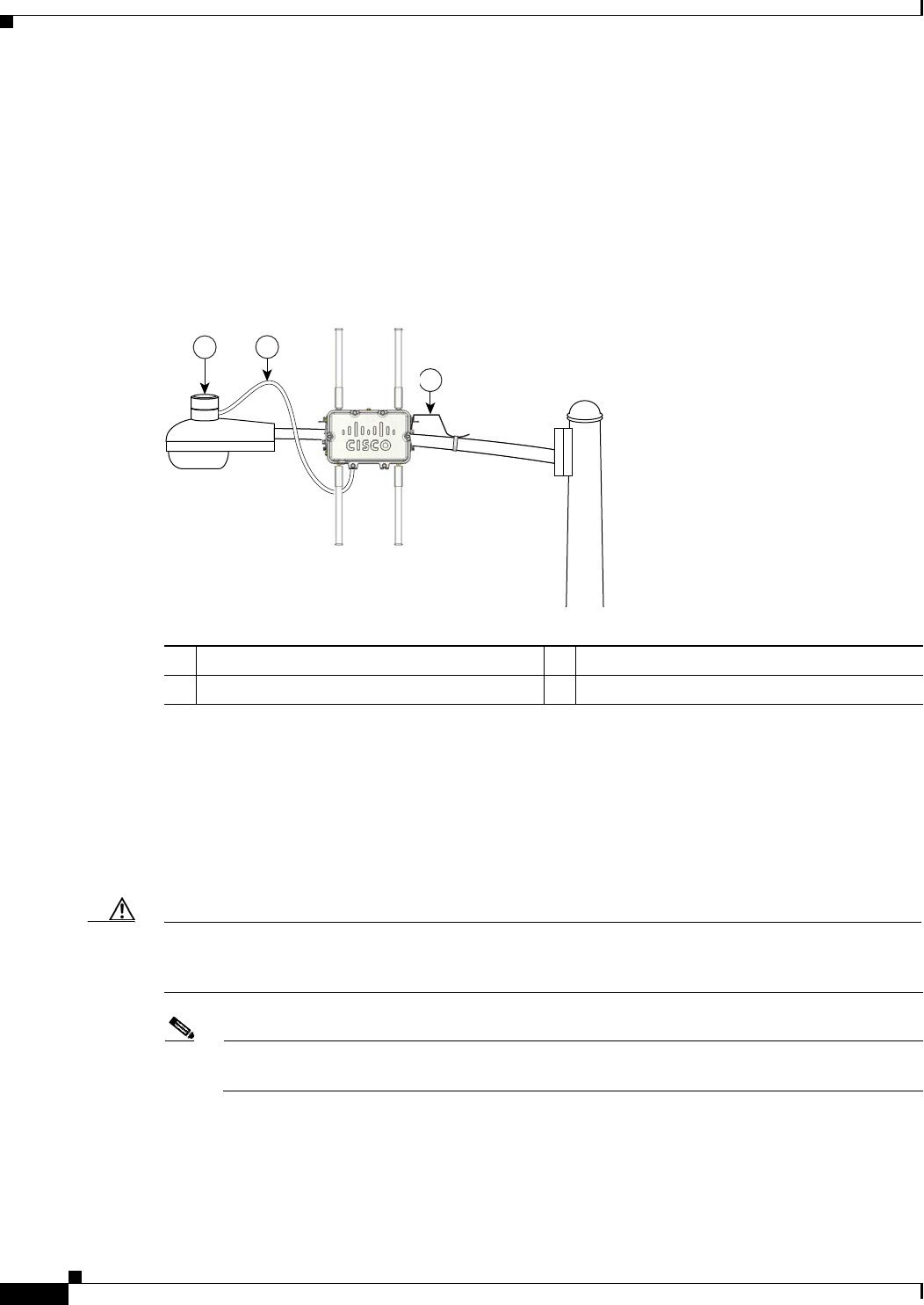
Step 15 When using the optional Cisco external omnidirectional antennas, connect them to the access point as
shown in Figure 2-2. Hand-tighten the antennas to the access point.
Step 16 Continue with the “Grounding the Access Point” section on page 2-46 and the “Powering the Access
Point” section on page 2-50.

REVIEW DRAFT—CISCO CONFIDENTIAL
2-30
Cisco Aironet 1520 Series Outdoor Mesh Access Point Hardware Installation Guide
OL-12632-03
Chapter 2 Mounting Instructions
Mounting the Access Point
Cable Strand Mounting
When mounting the access point on a cable strand, you must use the optional strand mount kit. The kit
contains several parts that you should assemble before mounting on a cable strand. To install the access
point to a cable strand, you need to perform these operations:
• Attach cable clamps to the clamp bracket
• Attach the strand bracket to the access point
• Attach the clamp bracket to the fiber or cable strand
• Attach the strand bracket (with access point) to the clamp bracket
• Attach antennas
• Attach a ground wire
• Connect cables and power to the access point
Note The access point must be installed on a cable strand by a professional cable installer.
To mount the access point preform these steps:
Step 1 Install two cable clips, a flat washer, and a M8 flange nut on each clamp support bolt on the front of the
clamp bracket (see Figure 2-16). You should only hand-tighten the nuts sufficiently to prevent them
from falling off.
REVIEW DRAFT—CISCO CONFIDENTIAL
2-31
Cisco Aironet 1520 Series Outdoor Mesh Access Point Hardware Installation Guide
OL-12632-03
Chapter 2 Mounting Instructions
Mounting the Access Point
Figure 2-16 Clamp Bracket with Cable Clamps
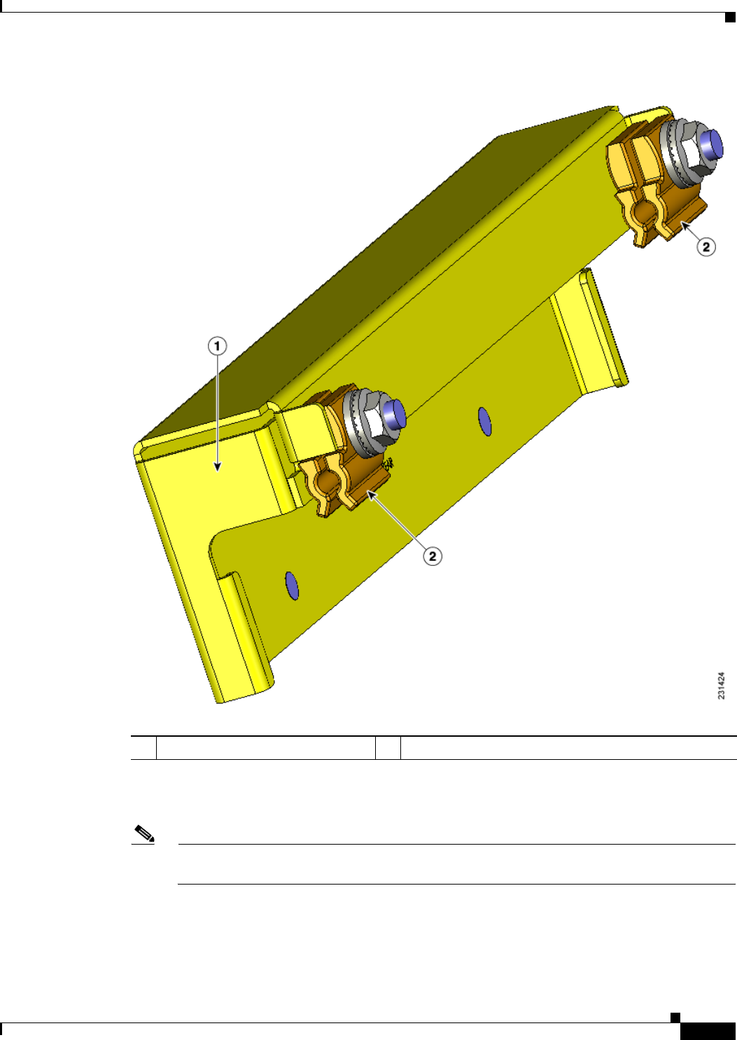
Step 2 Attach the strand bracket to the access point using two M8 x16 bolts (with flat and lock washers) on each
side of the access point (see Figure 2-17). Only hand-tighten the bolts.
Note When attached to the cable strand, the access point must be vertically adjusted before the final
tightening of the bolts.
1Cable strand bracket 2Two cable clamps, flat washer, and M8 flange nut.
REVIEW DRAFT—CISCO CONFIDENTIAL
2-32
Cisco Aironet 1520 Series Outdoor Mesh Access Point Hardware Installation Guide
OL-12632-03
Chapter 2 Mounting Instructions
Mounting the Access Point
Figure 2-17 Strand Bracket Attached to Access Point
1Strand bracket 3Second M8 x16 bolt (with flat and lock
washers)
2First M8 x16 bolt
(with flat and lock washers)
REVIEW DRAFT—CISCO CONFIDENTIAL
2-33
Cisco Aironet 1520 Series Outdoor Mesh Access Point Hardware Installation Guide
OL-12632-03
Chapter 2 Mounting Instructions
Mounting the Access Point
Step 3 Place the clamp bracket on the strand support cable (see Figure 2-18). On each cable support bolt, ensure
that one cable clamp is placed on each side of the support cable (see Figure 2-20). Tighten the two M8
flange nuts to 13 to 15 in. lbs (17.6 to 20.3 Nm).
Figure 2-18 Clamp Bracket Attached to Cable Strand
1Two cable clips, flat washer, and a M8 flange nut on each cable support bolt
REVIEW DRAFT—CISCO CONFIDENTIAL
2-34
Cisco Aironet 1520 Series Outdoor Mesh Access Point Hardware Installation Guide
OL-12632-03
Chapter 2 Mounting Instructions
Mounting the Access Point
Figure 2-19 Location of Strand Clips
Note The strand support cable might have to be pulled away from the fiber or cable bundle. Be sure
to resecure the cable as necessary.
Note The strand support cable and the mounting hardware provide grounding for the access point.
1Strand clamp bracket 5Fiber or cable bundle
2Flat washer 6Cable clip
3M8 flange nut 7Cable clip
4Strand support cable
REVIEW DRAFT—CISCO CONFIDENTIAL
2-35
Cisco Aironet 1520 Series Outdoor Mesh Access Point Hardware Installation Guide
OL-12632-03
Chapter 2 Mounting Instructions
Mounting the Access Point
Step 4 Select the appropriate hole pair (see Figure 2-20) for the orientation of the cable strand where you will
mount your access point.
The strand bracket contains several support hole pairs that allows the user to mount the access point onto
cable strands that are horizontal or sloped (see Figure 2-20). Depending on the orientation of the cable
strand, the access point is supported by these hole pairs:
• H fixed hole pair used for a horizontal cable strand.
• R fixed and R adjustable hole pair used for a cable strand sloping up to the right.
• L fixed and L adjustable hole pair used for a cable strand sloping up to the left.
Figure 2-20 Strand Bracket Support Holes
1R fixed and adjustable support holes 3H fixed support holes
2L fixed and adjustable support holes
REVIEW DRAFT—CISCO CONFIDENTIAL
2-36
Cisco Aironet 1520 Series Outdoor Mesh Access Point Hardware Installation Guide
OL-12632-03
Chapter 2 Mounting Instructions
Mounting the Access Point
Step 5 Insert the two support bolts located on back of the clamp bracket (see Figure 2-21) into the strand bracket
support hole pairs for your strand orientation. Screw two M8 flange nuts on the support bolts, and tighten
to 13 to 15 in. lbs (17.6 to 20.3 Nm).
Figure 2-21 Attaching Strand Bracket to Clamp Bracket
1Left support bolt and M8 flange nut 3Strand bracket
2Right support bolt and M8 flange nut
REVIEW DRAFT—CISCO CONFIDENTIAL
2-37
Cisco Aironet 1520 Series Outdoor Mesh Access Point Hardware Installation Guide
OL-12632-03
Chapter 2 Mounting Instructions
Mounting the Access Point
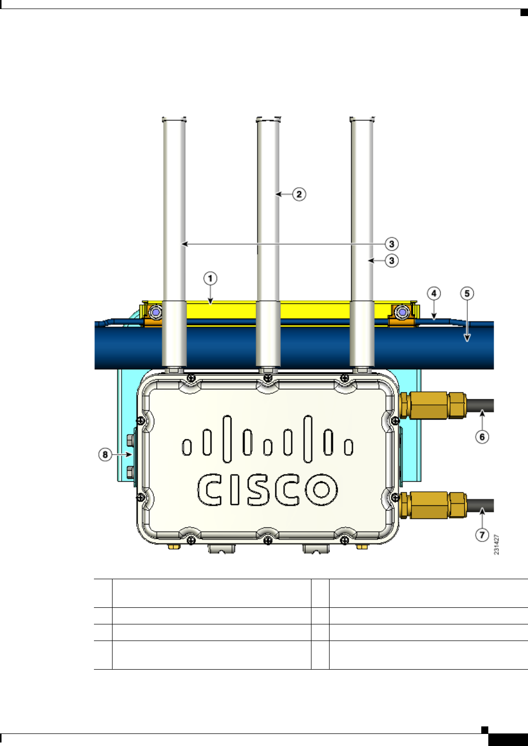
Step 6 When using the optional Cisco external omnidirectional antennas, connect them to the access point as
shown in Figure 2-22.
Figure 2-22 Access Point Mounted to Cable Strand
1Clamp bracket with cable clamps
(part of strand mount kit)
5Cable strand (only one strand shown)
25-GHz antenna1
1. Illustration shows antennas for an access point with two radios.
6Fiber-optic cable connection
32.4-GHz antennas17Cable POC power input
4Support cable 8Strand mount bracket
(part of strand mount kit)

REVIEW DRAFT—CISCO CONFIDENTIAL
2-38
Cisco Aironet 1520 Series Outdoor Mesh Access Point Hardware Installation Guide
OL-12632-03
Chapter 2 Mounting Instructions
Mounting the Access Point
Step 7 Continue with the “Grounding the Access Point” section on page 2-46 and the “Powering the Access
Point” section on page 2-50.
Opening the Access Point Hinged Cover
You need to open the access point hinged cover when you are performing these operations:
• Installing a cable POC Stinger connector
• Installing fiber-optic SFP module and fiber cable take-up reels
To open the access point hinged cover, follow these steps:
Step 1 Use 0.5-in. (13-mm) box-end wrench or socket set to unscrew the six bolts on the front cover of the unit.
Only unscrew the bolts about 2 turns until they are easily turned by hand, do not remove the bolts.
Step 2 The cover is hinged on the bottom. Carefully open the cover and swing it down.
Note If the cover does not swing open easily, carefully loosen the hinge bolts again.
REVIEW DRAFT—CISCO CONFIDENTIAL
2-39
Cisco Aironet 1520 Series Outdoor Mesh Access Point Hardware Installation Guide
OL-12632-03
Chapter 2 Mounting Instructions
Mounting the Access Point
Figure 2-23 Access Point Front View
Closing the Access Point Hinged Cover
To close the access point cover, follow these steps:
Step 1 When closing the access point cover, be careful not to pinch internal wires.
Step 2 Carefully position the cover flush with all sides of the access point, then slowly hand-tighten each bolt.
Step 3 When all bolts are hand-tightened, use a 13 mm closed-end wrench or socket to partially tighten the bolts
in the tightning sequence shown in Figure 2-24. Tighten each bolt to 3 to 4 ft lbs ( 0.34 to 0.45 Nm).
Step 4 Repeat Step 3 using the same tightning sequence to fully tighten each bolt to 6 to 7 ft lbs
(0.68 to 0.79 Nm).
1M8 x32 bolts 2Cover hinge M8 x32 bolts
REVIEW DRAFT—CISCO CONFIDENTIAL
2-40
Cisco Aironet 1520 Series Outdoor Mesh Access Point Hardware Installation Guide
OL-12632-03
Chapter 2 Mounting Instructions
Mounting the Access Point
Figure 2-24 Hinged Cover Bolt Tightning Sequence - New PIcture Needed
REVIEW DRAFT—CISCO CONFIDENTIAL
2-41
Cisco Aironet 1520 Series Outdoor Mesh Access Point Hardware Installation Guide
OL-12632-03
Chapter 2 Mounting Instructions
Mounting the Access Point
Using the Reset Button
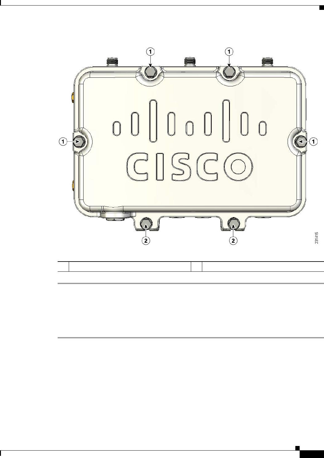
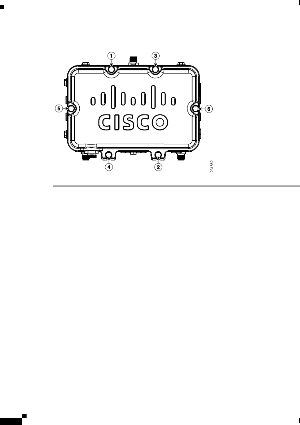
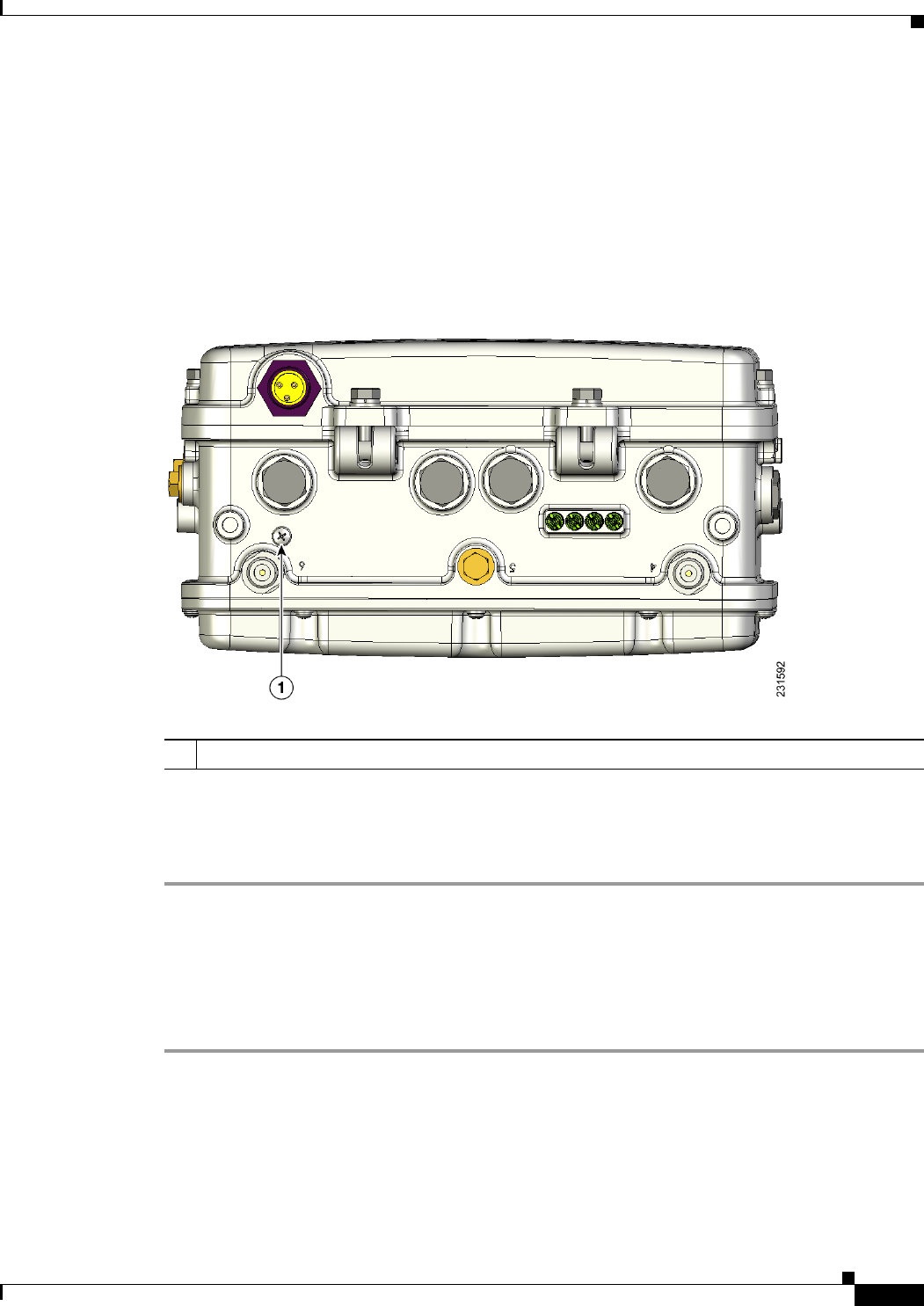
The access point has a reset button located on the bottom of the unit (see Figure 2-25). The reset button
is recessed in a small hole that is sealed with a screw and a rubber gasket. The reset button can be used
to perform these functions:
• Reset the access point—press the reset button for less than 10 seconds.
• Disable battery backup power—press the reset button for more than 10 seconds.
Figure 2-25 Reset Button Location
Reboot the Access Point
To reboot (power cycle) the access point, follow these steps:
Step 1 Use a Phillips screwdriver to remove the reset button screw. Be careful not to loose the screw.
Step 2 Use a straighten paperclip, and push the reset button for less than 10 seconds. This causes the access
point to reboot (power cycle), all LEDs turn off for approximately 5 seconds and then the LEDs
reactivate.
Step 3 Replace the reset button screw, and use a Phillips screwdriver to tighten to 22 to 24 in. lbs
(2.49 to 2.71 Nm).
1Reset button location

REVIEW DRAFT—CISCO CONFIDENTIAL
2-42
Cisco Aironet 1520 Series Outdoor Mesh Access Point Hardware Installation Guide
OL-12632-03
Chapter 2 Mounting Instructions
Installing the Access Point in Hazardous Locations
Disabling Backup Battery Power
To disable battery backup power, follow these steps:
Step 1 Use a Phillips screwdriver to remove the reset button screw. Be careful not to loose the screw.
Step 2 Use a straighten paper clip and push the reset button for greater than 10 seconds.
• When the access point is only battery powered, this causes the access point to reboot and then
disable the backup battery power. The LEDs turn off for approximately 5 seconds, reactivate for
approximately 5 seconds, and then turn off and stay off.
• When the access point has battery power and another power source, this causes the access point to
reboot, then disable the battery and continue operating from the second power source. The LEDs
turn off for approximately 5 seconds and then reactivate.
Note If your access point does not contain a battery backup unit, the access point will only reboot.
Note The battery backup unit is reactivated when the access point is rebooted (power cycled)
again.
Step 3 Replace the reset button screw, and use a Phillips screwdriver to tighten to 22 to 24 in. lbs
(2.49 to 2.71 Nm).
Installing the Access Point in Hazardous Locations
The access point’s hazardous location option complies with safety standards for Class I, Division 2,
Zone 2 hazardous locations. (Where ignitable concentrations of flammable gases, vapors or liquids are
not likely to exist under normal operation conditions). When you order
When you select the hazardous location option as part of the ordering process, Cisco configures the
system to contain the new components. A conduit adaptor and assembly instructions is placed in the
shipping box that provides information and assembly procedures. The hazardous location option
configures the access point as follows:
• The battery pack is removed because battery construction does not meet hazardous location
requirements.
• The AC power connections are moved to the inside of the access point by installing an AC entry
board containing a terminal block. To comply with hazardous location requirements, AC power
must be installed through rigid metal conduit to the terminal block.
• Two PG13 - 1/2 NPT adapters are provided. The adapter connects the conduit to the access point’s
AC power port.
• When used in hazardous locations, the access point is rated 100–240 vac only.
This section describes the steps required to retrofit the access point and prepare it for installation in Class
I, Division 2, Zone 2 hazardous locations.

REVIEW DRAFT—CISCO CONFIDENTIAL
2-43
Cisco Aironet 1520 Series Outdoor Mesh Access Point Hardware Installation Guide
OL-12632-03
Chapter 2 Mounting Instructions
Installing the Access Point in Hazardous Locations
Warnings
Warning
Do not disconnect connections to this equipment unless power has been removed or you have verified
that the area is nonhazardous. Secure any external connections that mate to this equipment by using
screws, sliding latches, threaded connectors, or other means provided with this product. Substitution
of components may impair suitability for Class I, Division 2.
Statement 1062
Warning
When used in a Class I, Division 2 hazardous location, this equipment must be mounted with a proper
wiring method that complies with the governing electrical codes.
Statement 1069
Warning
If you connect or disconnect the console cable with power applied to the unit or any device on the
network, an electrical arc can occur. This could cause an explosion in hazardous location
installations. Be sure that power is removed or the area is nonhazardous before proceeding.
To verify unit operation, perform POST on the device in a nonhazardous location before installation.
Statement 1080
Compliance
An access point complies with the following hazardous location certifications:
• IEC 60079-0
• IEC 60079-15
• CAN/CSA E60079-0
• CAN/CSA E60079-15
• UL 60079-0
• UL 60079-15
• EN 600079-0
• EN 60079-15
Compliance Label
Table 4 shows the access point hazardous location compliance label.
Figure 26 Hazardous Location Compliance Label
ILLUSTRATION TO BE ADDED
Table 4 interprets the information on the compliance label.

REVIEW DRAFT—CISCO CONFIDENTIAL
2-44
Cisco Aironet 1520 Series Outdoor Mesh Access Point Hardware Installation Guide
OL-12632-03
Chapter 2 Mounting Instructions
Installing the Access Point in Hazardous Locations
Ta b l e 4 Interpreting the Hazardous Compliance Label
Label Marking Description
Class I, Division 2,
Groups A, B, C, D
Defines the environment in which the access point can be used:
• Class I—Environment containing flammable gases, vapors, or
liquids
• Division 2—Environmental classification used by the U.S. and
Canada
• Groups A, B, C, D—Gas identification for the U.S. and
Canada:
–
A—Acetylene
–
B—Hydrogen
–
C—Ethylene
–
D—Propane
Class I, Zone 2, Group II Classification for Europe and the rest of the world. Group II is a gas
group which includes IIA, IIB, IIC:
• IIA = propane
• IIB = ethylene
• IIC = acetylene & hydrogen
AEx nA II T5 Defines North American explosive atmospheres for the class and
division:
• Ex —Denote explosive atmosphere
• nA —Non-sparking
• II = group II as defined previously
• T5 = Temperature code < 100 degrees C, maximum surface
temperature
Ex nA II T5 This marking is the same as AEx line except it is for the IECEx
certification. IECEx certification is the international scheme for
explosive atmosphere.
-40 < Ta < 55C The operating temperature range for the access point in all
countries.
Type 4, IP67 Defines the enclosure’s degree of protection (Type 4 = indoor or
outdoor use primarily to provide a degree of protection against
windblown dust and rain, splashing water, hose-directed water, and
damage from external ice formation. IP67 = Dust tight, protected
against the effects of temporary immersion in water.
CSA Certificate 1945576 CSA certification number

REVIEW DRAFT—CISCO CONFIDENTIAL
2-45
Cisco Aironet 1520 Series Outdoor Mesh Access Point Hardware Installation Guide
OL-12632-03
Chapter 2 Mounting Instructions
Installing the Access Point in Hazardous Locations
Installing the Conduit Adapter
Follow these steps to install the conduit adapter on the access point AC power port.
Step 1 TBD NEED A PROCEDURE FOR THIS.
Step 2
Routing and Connecting AC Power to the Access Point
You must route AC power to the access point using rigid steel conduit. When you install the conduit, be
sure to comply with the local electrical codes for your area.
Once the conduit is installed, follow these steps to connect the conduit to the access point’s power port
and connect them to the AC terminal block.
Step 1 TBD NEED A PROCEDURE FOR THIS ALSO
Step 2
Mounting the Access Point
You can mount the access point using any of the mounting systems described in this document. Follow
the instructions in the appropriate section or sections.
IECEx Certificate XXXXXX IECEx certificate number. Technical evaluation has been
completed and quality assessment is in progress. Certificate will be
issued when quality assessment is complete.
II 3 G Ex nA II T5 EU marking to indicate the product complies with the ATEX
directive:
• Ex—EU symbol to denote explosive atmosphere
• II— Equipment group. Group II identifies surface
(non-mining) equipment
• 3—Equipment category. Category 3 is equivalent to Zone 2
• G—Type of flammable substance, G identifies Gas (vs. D is for
dust)
• nA—Non-sparking
• T5 —Temperature code defining < 100 degrees C, maximum
surface temperature
Label Marking Description

REVIEW DRAFT—CISCO CONFIDENTIAL
2-46
Cisco Aironet 1520 Series Outdoor Mesh Access Point Hardware Installation Guide
OL-12632-03
Chapter 2 Mounting Instructions
Grounding the Access Point
Grounding the Access Point
See the “Grounding the Access Point” section on page 2-46 for grounding instructions.
Grounding the Access Point
The access point must be grounded prior to connecting power.
Warning
This equipment must be externally grounded using a customer-supplied ground wire before power is
applied. Contact the appropriate electrical inspection authority or an electrician if you are uncertain
that suitable grounding is available.
Statement 366
Warning
Installation of the equipment must comply with local and national electrical codes.
Statement 1074
Note When the access point is cable strand mounted, the strand support cable and the mounting hardware
provide grounding for the access point.
In all outdoor installations and when powering the access point with AC power, you must follow these
instructions to properly ground the case:
Step 1 If using insulated 6-AWG copper ground wire, strip the insulation as required for the grounding lug.
Step 2 Use the appropriate crimping tool to crimp the bare 6-AWG copper ground wire to the supplied
grounding lug (Panduit PLCD6-10A-L).
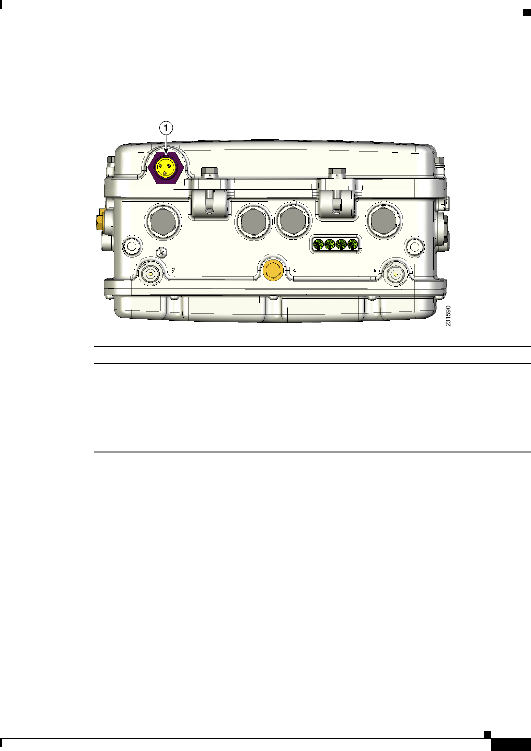
Step 3 Open the electrical joint compound (supplied), and apply a liberal amount over the metal surface where
the ground strap screw holes are located (see Figure 2-14).
Step 4 Connect the grounding lug to the access point grounding screw holes (see Figure 2-14) using the
supplied two Phillips head screws (M4 x10 mm) with lock washers. Tighten the grounding screw to
22 to 24 in. lbs (2.49 to 2.71 Nm).
Step 5 If necessary, strip the other end of the ground wire, and connect it to a reliable earth ground such as a
grounding rod (see Figure 2-2), an appropriate grounding point on a metal streetlight pole that is
grounded (see Figure 2-32), or a grounded cable on a cable strand.
Connecting a Fiber-Optic Cable to the Access Point
The fiber-optic kit (GLC-FE-100BX-URGD=) enables the access point to support fiber-optic network
connections. The kit contains these parts:
• 100BASE-BX10-U rugged SFP module
–
Single strand fiber bidirectional optical transceiver
–
1.3/1.5 micro-meter wavelength division multiplexing (WDM) function
–
125-Mb/s data rates

REVIEW DRAFT—CISCO CONFIDENTIAL
2-47
Cisco Aironet 1520 Series Outdoor Mesh Access Point Hardware Installation Guide
OL-12632-03
Chapter 2 Mounting Instructions
Connecting a Fiber-Optic Cable to the Access Point
–
Single mode LC receptacle
• Eight screws
• Two small take-up reels
• Two large take-up reels
• One liquid tight adapter—accepts a cable diameter of 0.20 to 0.35 in. (0.51 to 0.89 cm)
Warning
Class 1 laser product.
Statement 1008
Note You need a customer supplied outdoor-rated fiber-optic cable with an LC connector. The cable diameter
must be 0.20 to 0.35 in. (0.52 to 0.89 cm) in diameter.
To connect a fiber-optic cable to the access point, follow these steps:
Step 1 Ensure that all power sources have been disconnected from the access point.
Warning
This unit might have more than one power supply connection. All connections must be removed to
de-energize the unit.
Statement 1028
Note If your access point contains a backup battery pack, you must depress the reset button for
10 seconds or more (see the “Disabling Backup Battery Power” section on page 2-42).
Step 2 Open the hinged cover (see the “Opening the Access Point Hinged Cover” section on page 2-38 for
instructions).
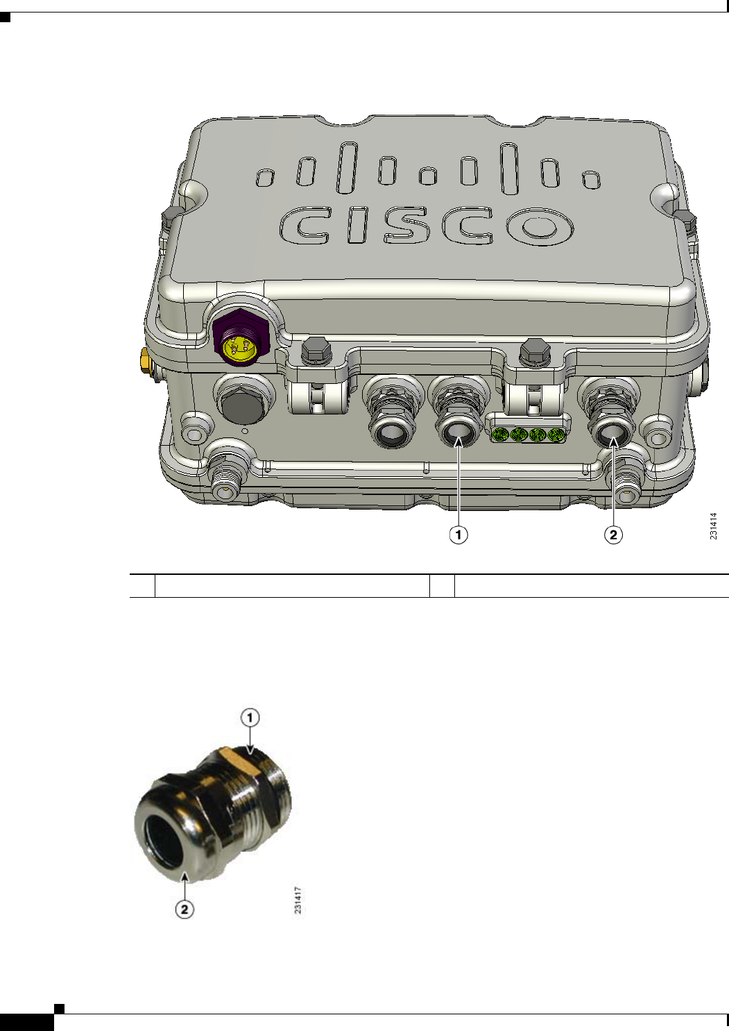
Step 3 For cable strand deployments, remove the SCTE 5/8 plug (item 1 in Figure 2-27) using a 13 mm wrench
or socket. For all other deployments, remove the fiber-optic connector plug (item 5 in Figure 2-27) using
an adjustable wrench, the 22 mm socket, or the Sealcon S-22-WR wrench.
Step 4 Place the two large reels with the small reels on top as shown in Figure 2-27.
Step 5 Align the screw holes in the large and small reels, and insert four attachment screws in each of the reel
pairs. Tighten the screws to 3 to 4 in. lbs (0.34 to 0.45 Nm).
Step 6 Remove the plug from the end of the SFP module, and insert the module into the SFP receptacle (see
Figure 2-27).
REVIEW DRAFT—CISCO CONFIDENTIAL
2-48
Cisco Aironet 1520 Series Outdoor Mesh Access Point Hardware Installation Guide
OL-12632-03
Chapter 2 Mounting Instructions
Connecting a Fiber-Optic Cable to the Access Point
Figure 2-27 Fiber-Optic Cable Components
1SCTE 5/8 plug 4Four screws for each reel assembly
2SFP module slot 5Fiber-optic connector plug
3Fiber reels (large reel with small reel on top)
REVIEW DRAFT—CISCO CONFIDENTIAL
2-49
Cisco Aironet 1520 Series Outdoor Mesh Access Point Hardware Installation Guide
OL-12632-03
Chapter 2 Mounting Instructions
Connecting a Fiber-Optic Cable to the Access Point
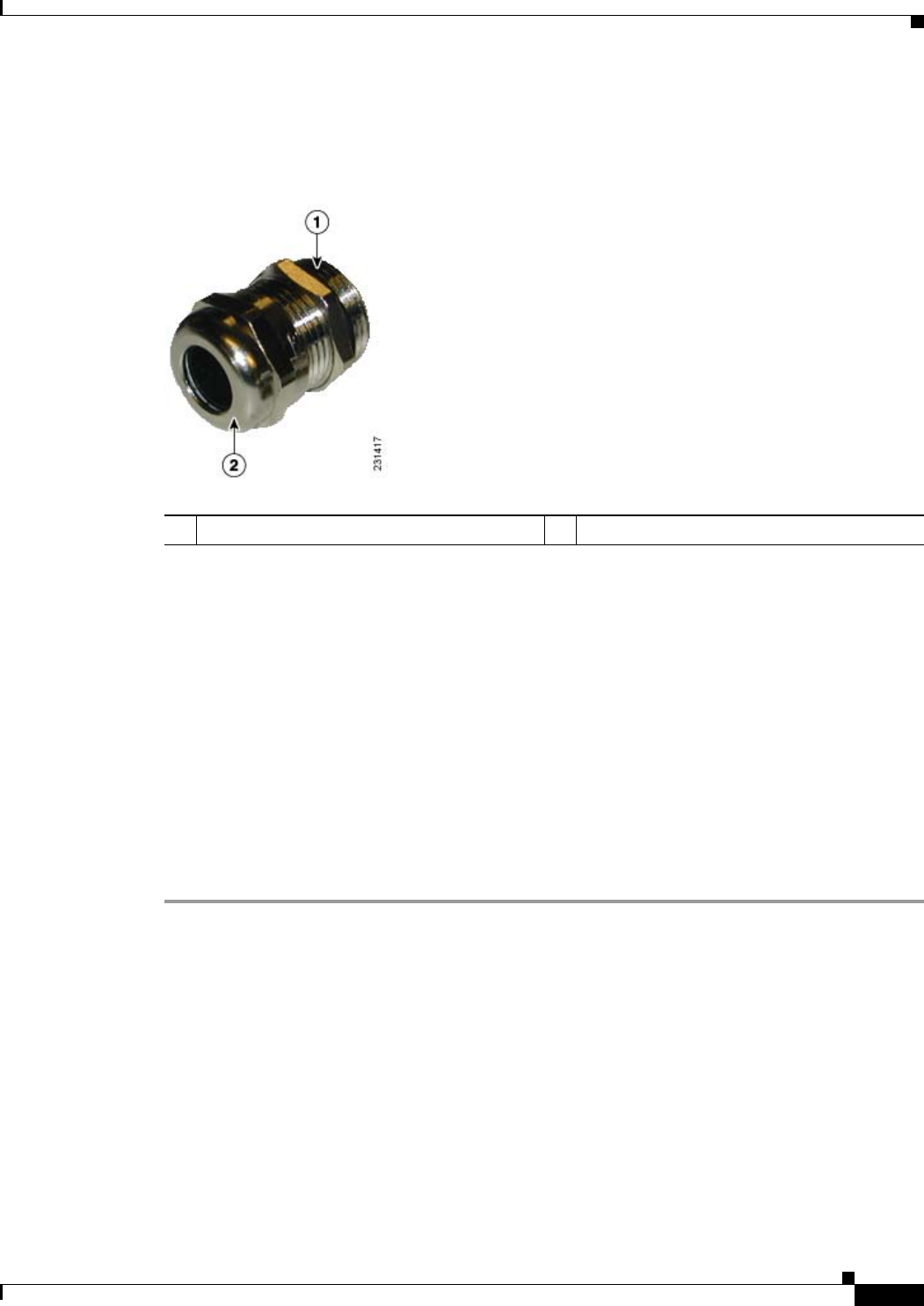
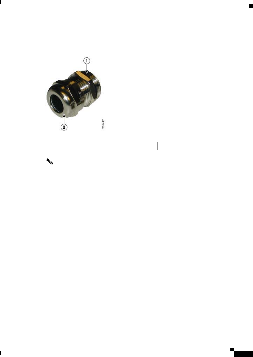
Step 7 Loosen the round end of the liquid tight connector by turning counterclockwise, but do not remove (see
Figure 2-28).
Figure 2-28 Liquid -Tight Adapter
Step 8 Carefully screw the threaded end of the adapter into the access point and hand-tighten.
Step 9 Use an adjustable wrench, the 22 mm socket, or the Sealcon S-2200-WR wrench to tighten the threaded
end of the adapter to 6 to 7 ft lbs ( 8.1 to 9.5 Nm).
Step 10 Carefully remove approximately 1 to 2 ft (30.5 cm) of the external jacket from the fiber-optic cable,
exposing the inner strand.
Step 11 Carefully insert the fiber-optic LC cable connector into the rounded end of the liquid tight adapter (see
Figure 2-28), and push through the adapter.
Step 12 Wrap excess fiber-optic cable around the take-up reels in a figure 8 pattern.
Step 13 Insert the fiber-optic LC cable connector into the SFP module.
Step 14 Use an adjustable or open-end wrench to tighten the round end of the adapter to 2.7 to 3.2 ft lbs
(3.66 to 4.34 Nm).
Step 15 Close the hinged cover (see the “Closing the Access Point Hinged Cover” section on page 2-39).
1Thread end 2Round end

REVIEW DRAFT—CISCO CONFIDENTIAL
2-50
Cisco Aironet 1520 Series Outdoor Mesh Access Point Hardware Installation Guide
OL-12632-03
Chapter 2 Mounting Instructions
Powering the Access Point
Powering the Access Point
The access point can be powered by one of these methods:
• PoE—56 VDC
–
Connecting a 1520 Series Power Injector, page 2-50
• AC power
–
100 to 480 VAC—Connecting Streetlight AC Power, page 2-55
–
120 VAC—Connecting an AC Power Cable to the Access Point, page 2-58
• External 12 VDC
–
Connecting a DC Power Cable to the Access Point, page 2-59
• POC—40 to 90 VAC (Quasi-AC)
–
Connecting a Cable POC Power to the Access Point, page 2-63
Connecting a 1520 Series Power Injector
The power injector provides 56 VDC to the access point over the Ethernet cable and supports a total
end-to-end Ethernet cable length of 100 m (328 ft) from the switch to the access point.
Note The cable from the power injector to the access point (PoE-in port) must be at least 10 ft (3.05 m) long.
Note The PoE-out port is disabled when the access point is powered by the power injector.
When your access point is powered by an optional power injector, follow these steps to complete the
installation:
Step 1 Before applying PoE to the access point, ensure the access point is grounded (see the “Grounding the
Access Point” section on page 2-46.
Step 2 Review Figure 2-2 to identify the components needed for the installation.
Note The 1520 power injector can only be used in an indoor environment.
Step 3 Connect a CAT5e or better Ethernet cable from your wired LAN network to the power injector.
Warning
To reduce the risk of fire, use only No. 26 AWG or larger telecommunication line cord.
Statement 1023
Use only the 1520 power injector (AIR-PWRINJ1500-2) for the access point. This power injector is
designed to meet the power requirements of the access point and is a listed Class 2 limited power source
(LPS).

REVIEW DRAFT—CISCO CONFIDENTIAL
2-51
Cisco Aironet 1520 Series Outdoor Mesh Access Point Hardware Installation Guide
OL-12632-03
Chapter 2 Mounting Instructions
Powering the Access Point
Tip To forward bridge traffic, add a switch between the power injector and controller. Refer to the
Deployment Guide: Cisco Mesh Networking Solution for more information.
Step 4 Ensure that the antennas are connected and that a ground is attached to the access point before you apply
power to the access point.
Step 5 Connect a shielded outdoor-rated Ethernet (CAT5e or better) cable between the power injector and the
access point’s PoE-in connector (see Figure 2-29).
Step 6 Connect the Ethernet cable to the access point PoE-in port (see “Connecting an Ethernet Cable to the
Access Point” section on page 2-51).
Step 7 Continue with the “What to Do Next” section on page 2-65.
Connecting an Ethernet Cable to the Access Point
You need to supply these tools and materials:
• Shielded outdoor-rated Ethernet (CAT5e or better) cable with 0.2 to 0.35 in. (0.51 to 0.89 cm)
diameter
Note The Ethernet cable from the power injector to the access point must be at least 10 ft
(3.05 m) long. The PoE-out port is disabled when the access point is powered by the power
injector.
• RJ-45 connector and installation tool
• Adjustable wrench
To connect the shielded Ethernet cable to the access point, follow these steps:
Step 1 Disconnect power to the power injector, and ensure all power sources to the access point are turned-off.
Warning
This unit might have more than one power supply connection. All connections must be removed to
de-energize the unit.
Statement 1028
Note If your access point contains a backup battery pack, you must press the reset button for 10
seconds or more (see the “Disabling Backup Battery Power” section on page 2-42).
Step 2 Ensure a 6 AWG ground wire is connected to the access point (see the “Grounding the Access Point”
section on page 2-46).
Step 3 Use an adjustable wrench, a 22 mm socket, or the Sealcon S-2200-WR wrench to remove the Ethernet
connector plug from the access point (see Figure 2-29 for the location).
REVIEW DRAFT—CISCO CONFIDENTIAL
2-52
Cisco Aironet 1520 Series Outdoor Mesh Access Point Hardware Installation Guide
OL-12632-03
Chapter 2 Mounting Instructions
Powering the Access Point
Figure 2-29 Location of Ethernet Liquid -Tight Adapters
Step 4 Loosen the round end of the liquid tight adapter by turning counterclockwise, but do not remove (see
Figure 2-30).
Figure 2-30 Liquid Tight Adapter
1PoE-out port 2PoE-in port

REVIEW DRAFT—CISCO CONFIDENTIAL
2-53
Cisco Aironet 1520 Series Outdoor Mesh Access Point Hardware Installation Guide
OL-12632-03
Chapter 2 Mounting Instructions
Powering the Access Point
Step 5 Insert the unterminated end of the Ethernet cable into the round end of the liquid tight adapter (see
Figure 2-30), and pull several inches of cable through the adapter.
Step 6 Install an RJ-45 connector on the unterminated end of the Ethernet cable using your Ethernet cable
installation tool.
Warning
To reduce the risk of fire, use only No. 26 AWG or larger telecommunication line cord.
Statement 1023
Step 7 Carefully insert the RJ-45 cable connector into the Ethernet port opening on the access point, and
connect to the internal Ethernet connector (see Figure 2-31).
1Thread end 2Round end
REVIEW DRAFT—CISCO CONFIDENTIAL
2-54
Cisco Aironet 1520 Series Outdoor Mesh Access Point Hardware Installation Guide
OL-12632-03
Chapter 2 Mounting Instructions
Powering the Access Point
Figure 2-31 Inserting RJ-45 Connector into the Ethernet Port Opening in Case
Step 8 Slide the liquid tight adapter towards the access point, and screw the threaded end of the adapter into the
access point, and hand-tighten.
Step 9 Use an adjustable wrench, a 22 mm socket, or a Sealcon S-2200-WR wrench to tighten the threaded end
of the adapter to 6 to 7 ft lbs (8.1 to 9.5 Nm).
Step 10 Use an adjustable wrench and tighten the round end of the adapter to 2.7 to 3.2 ft lbs (3.66 to 4.34 Nm).
Step 11 Ensure that the antennas are connected to the access point before you apply power to the access point.
Step 12 Route your Ethernet cable, and cut off any excess cable.
Step 13 Install an RJ-45 connector on the unterminated cable end, and insert it into the power injector. For
typical installation components see Figure 2-2.
Step 14 Turn on power to the power injector.
1Liquid tight adapter 3RJ-45 connector
2Ethernet port opening in access point case 4Shielded outdoor-rated Ethernet (CAT5e or
better) cable

REVIEW DRAFT—CISCO CONFIDENTIAL
2-55
Cisco Aironet 1520 Series Outdoor Mesh Access Point Hardware Installation Guide
OL-12632-03
Chapter 2 Mounting Instructions
Powering the Access Point
Connecting Streetlight AC Power
The access point can be installed on a streetlight pole and powered from a streetlight outdoor light
control using the optional streetlight power tap adapter.
Caution The access point can be powered by a light pole twist-lock outdoor light control that provides
100-to 480-VAC 50/60 Hz power. Do not connect to an outdoor light control powered by higher
voltages.
When powering the access point with AC power other than the streetlight power tap adapter, you must
ensure that the following conditions are observed:
1. AC power can be conveniently removed from the unit. The power should not be removed by
disconnecting the AC power connector on the unit.
Warning
A readily accessible two-poled disconnect device must be incorporated in the fixed wiring.
Statement 1022
Caution Before connecting or disconnecting a power cord, you must remove AC power from the power cord
using a suitable service disconnect.
2. You must protect any AC power plugs and AC receptacles from water and other outdoor elements.
You can use a UL-listed waterproofing enclosure suitable for covering the AC receptacle and AC
power plug that supplies power to the unit as described in Article 406 of the NEC.
3. When you install the access point outdoors or in a wet or damp location, the AC branch circuit that
powers the access point should have ground fault protection (GFCI), as required by Article 210 of
the National Electrical Code (NEC).
Warning
Be very careful when connecting the streetlight adapter to Category 3 pole-top power. If you are not
careful, you may electrocute yourself or fall.
Statement 363
For additional important safety instructions for AC power cords, refer to the AC Power Cords for Cisco
Aironet 1520 Series Outdoor Mesh Access Points document that shipped with your AC power cords.
To install an access point on a streetlight pole, follow these steps:
Step 1 Before beginning the installation, ensure the AC power to the streetlight pole is turned off.
Step 2 Turn off power to the AC power source at the designated circuits.
Warning
This unit might have more than one power supply connection. All connections must be removed to
de-energize the unit.
Statement 1028
Caution For your safety, when connecting the access point AC power connector, always connect the access point
end of the cable FIRST. When removing the AC power connector, always disconnect the access point
end of the cable LAST.
REVIEW DRAFT—CISCO CONFIDENTIAL
2-56
Cisco Aironet 1520 Series Outdoor Mesh Access Point Hardware Installation Guide
OL-12632-03
Chapter 2 Mounting Instructions
Powering the Access Point
If your access point contains a backup battery pack, you must press the reset button for 10 seconds or
more (see the “Disabling Backup Battery Power” section on page 2-42.)
Step 3 When using the streetlight power tap adapter (AIR-PWR-ST-LT-R3P=), ensure that the access point is
mounted within 3 ft (1 m) of the outdoor light control. For mounting instructions, refer to the “Mounting
the Access Point on a Pole” section on page 2-21.
Step 4 Ensure a 6-AWG ground wire is attached to the access point (see Figure 2-32) and connected to the
streetlight pole (for instructions see Grounding the Access Point, page 2-46).
Figure 2-32 Using the Streetlight Power Tap Adapter
Step 5 Refer to Figure 2-32. The streetlight power tap adapter uses a 3-pronged LC-10 twist-lock adapter that
is placed between the outdoor light control and its fixture. The LC-10 twist-lock adapter is designed to
be used with LC-10 listed outdoor light controls operating at 100 to 480 VAC, 50 to 60 Hz.
Step 6 Disconnect the outdoor light control from its fixture.
Step 7 Verify that the voltage available at the fixture is between 100 and 480 VAC, 50 to 60 Hz.
Step 8 Turn off power to the fixture at the designated circuits.
Caution When installing the streetlight power tap adapter to the access point AC power connector, always
connect the access point end of the cable FIRST. When removing the streetlight power tap adapter,
always disconnect the access point end of the cable last.
Note Ensure that your antennas are connected to the access point before you apply power to the access
point.
1Outdoor light control 36-AWG copper grounding wire
2Streetlight power tap adapter
231524
12
3
REVIEW DRAFT—CISCO CONFIDENTIAL
2-57
Cisco Aironet 1520 Series Outdoor Mesh Access Point Hardware Installation Guide
OL-12632-03
Chapter 2 Mounting Instructions
Powering the Access Point
Step 9 Connect the streetlight power tap adapter to the access point AC power connector, as shown in
Figure 2-33. Hand-tighten the connector.
Figure 2-33 AC Power Connector
Step 10 Plug the streetlight power tap adapter into the outdoor light control fixture, as shown in Figure 2-32.
Step 11 Plug the outdoor light control into the streetlight power tap adapter.
Step 12 Ensure that the antennas are connected to the access point before you apply power to the access point.
Step 13 Turn on the power to the outdoor light control fixture at the designated circuits.
1AC power connector

REVIEW DRAFT—CISCO CONFIDENTIAL
2-58
Cisco Aironet 1520 Series Outdoor Mesh Access Point Hardware Installation Guide
OL-12632-03
Chapter 2 Mounting Instructions
Powering the Access Point
Connecting an AC Power Cable to the Access Point
When powering the access point with AC power other than the streetlight power tap adapter, you must
ensure that the following conditions are observed:
1. AC power can be conveniently removed from the unit. The power should not be removed by
disconnecting the AC power connector on the unit.
Warning
A readily accessible two-poled disconnect device must be incorporated in the fixed wiring.
Statement 1022
Caution Before connecting or disconnecting a power cord, you must remove AC power from the power cord
using a suitable service disconnect.
2. You must protect any AC power plugs and AC receptacles from water and other outdoor elements.
You can use a UL-listed waterproofing enclosure suitable for covering the AC receptacle and AC
power plug that supplies power to the unit as described in Article 406 of the NEC.
3. When you install the access point outdoors or in a wet or damp location, the AC branch circuit that
powers the access point should have ground fault protection (GFCI), as required by Article 210 of
the National Electrical Code (NEC).
Note For additional important safety instructions for AC power cords, refer to the AC Power Cords for Cisco
Aironet 1520 Series Outdoor Mesh Access Points document that shipped with your AC power cords.
The access point supports this Cisco AC power cable:
• 40 ft (12.2 m) AC power cable (AIR-CORD-R3P-40NA=)
To connect an AC power cable to the access point, perform these steps:
Step 1 Prior to applying AC power, ensure the access point is grounded (see Grounding the Access Point,
page 2-46).
Step 2 Turn off power to the AC power source at the designated circuits.
Warning
This unit might have more than one power supply connection. All connections must be removed to
de-energize the unit.
Statement 1028
Caution When connecting the access point AC power connector, always connect the access point end of the cable
first. When removing the AC power connector, always disconnect the access point end of the cable last.
Note If your access point contains a backup battery pack, you must press the reset button for 10
seconds or more (see the “Disabling Backup Battery Power” section on page 2-42).

REVIEW DRAFT—CISCO CONFIDENTIAL
2-59
Cisco Aironet 1520 Series Outdoor Mesh Access Point Hardware Installation Guide
OL-12632-03
Chapter 2 Mounting Instructions
Powering the Access Point
Step 3 .Align the notch in the AC power cable connector with the key in the access point AC power connector,
and push the cable connector into the access point connector (see Figure 2-33). When fully seated, rotate
the cable connector ring clockwise until hand-tight.
Step 4 Ensure the antennas are connected to the access point before you apply power to the access point.
Step 5 Turn on the AC power at the designated circuits.
Connecting a DC Power Cable to the Access Point
When powering the access point with DC power, you must ensure that DC power can be conveniently
removed from the unit. The power should not be removed by disconnecting the DC power connector on
the unit.
Warning
A readily accessible two-poled disconnect device must be incorporated in the fixed wiring.
Statement 1022
Warning
Connect the unit only to DC power source that complies with the safety extra-low voltage (SELV)
requirements in IEC 60950 based safety standards.
Statement 1033
To connect a DC power cable, you need to supply these tools and material:
• Shielded outdoor-rated DC power cable with cable diameter of 0.20 to 0.35 in. (0.51 to 0.89 cm).
• Internal DC terminal connector
• Adjustable or open-end wrench
• Small flat screw driver
To connect the DC power cable to the access point, follow these steps:
Step 1 Before connecting DC power to the access point, ensure that the ground is connected to the access point
(see the “Grounding the Access Point” section on page 2-46.
Step 2 Turn off all power sources to the access point, including the DC power source.
Warning
This unit might have more than one power supply connection. All connections must be removed to
de-energize the unit.
Statement 1028
Caution When installing DC power to the access point, always connect the access point end of the cable first
When removing the DC power connector, always disconnect the access point end of the cable last.
If your access point contains a backup battery pack, you must press the reset button for 10 seconds or
more (see the “Disabling Backup Battery Power” section on page 2-42.)
REVIEW DRAFT—CISCO CONFIDENTIAL
2-60
Cisco Aironet 1520 Series Outdoor Mesh Access Point Hardware Installation Guide
OL-12632-03
Chapter 2 Mounting Instructions
Powering the Access Point
Step 3 Use an adjustable wrench, a 22 mm socket, or a Sealcon S-2200 -WR wrench to remove the plug in the
DC power connector opening (see Figure 2-34 for the location of the DC power connector).
Figure 2-34 Location of the DC Power Liquid Tight Adapter
1Ground lug screw holes 2DC power connector with liquid tight adapter
REVIEW DRAFT—CISCO CONFIDENTIAL
2-61
Cisco Aironet 1520 Series Outdoor Mesh Access Point Hardware Installation Guide
OL-12632-03
Chapter 2 Mounting Instructions
Powering the Access Point
Step 4 Loosen the round end of the liquid tight adapter by turning counterclockwise, but do not remove (see
Figure 2-35).
Figure 2-35 Liquid Tight Adapter
Note The liquid tight adapter accepts a cable diameter of 0.20 to 0.35 in. (0.51 to 0.89 cm).
Step 5 Insert a bare end of the DC power cable into the rounded end of the liquid tight adapter (see Figure 2-35),
and pull approximately 6 inches of cable through the adapter.
Step 6 Strip the DC cable jacket back about 1 inch to expose the wires and strip the insulation about 3/8 in. (9.5
mm) from each wire.
1Thread end 2Round end
REVIEW DRAFT—CISCO CONFIDENTIAL
2-62
Cisco Aironet 1520 Series Outdoor Mesh Access Point Hardware Installation Guide
OL-12632-03
Chapter 2 Mounting Instructions
Powering the Access Point
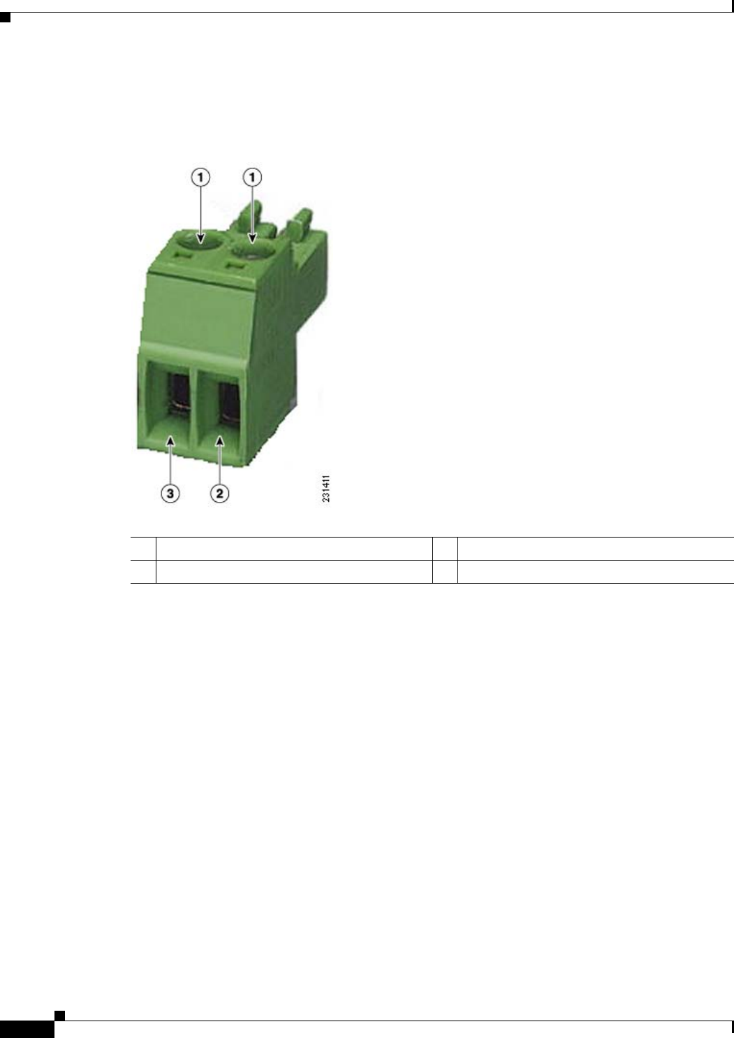
Step 7 Insert each wire into the two-position terminal strip (supplied), and tighten each wire using a 0.1 in.
(0.25 cm) flat screw driver (see Figure 2-36).
Figure 2-36 Two-Position Terminal Strip
1Securing screws 3Wire opening for DC +
2Wire opening for ground (DC return)
REVIEW DRAFT—CISCO CONFIDENTIAL
2-63
Cisco Aironet 1520 Series Outdoor Mesh Access Point Hardware Installation Guide
OL-12632-03
Chapter 2 Mounting Instructions
Powering the Access Point
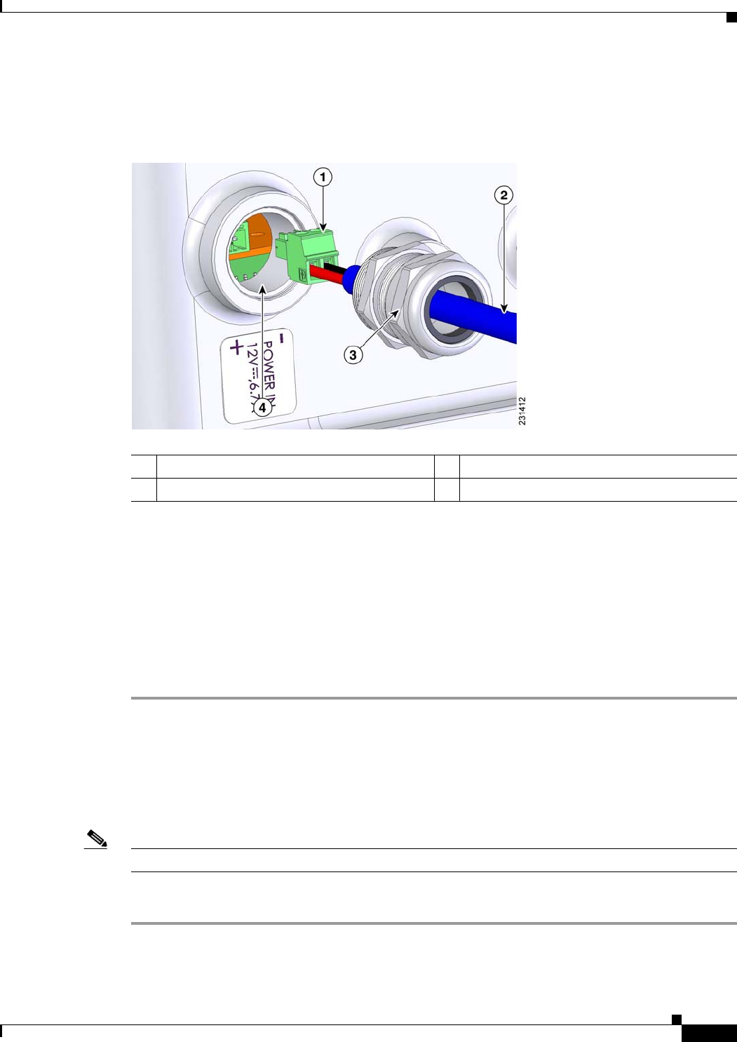
Step 8 Insert the two-position terminal strip into the DC power opening in the access point case, and carefully
push the terminal strip into the internal connector (see Figure 2-37).
Figure 2-37 Inserting the Terminal Strip into the DC Power Opening in the Access Point Case
Step 9 Slide the liquid tight adapter towards the access point, and screw the threaded end of the adapter into the
access point, and hand-tighten.
Step 10 Use an adjustable wrench, a 22 mm socket, or a Sealcon S-2200-WR wrench to tighten the threaded end
of the adapter to 6 to 7 ft lbs (8.1 to 9.5 Nm).
Step 11 Use an adjustable or open-end wrench to tighten the round end of the adapter to 2.7 to 3.2 ft lbs (3.66 to
4.34 Nm).
Step 12 Ensure that the antennas are connected to the access point before you apply power to the access point.
Step 13 Turn on the DC power at the designated circuits.
Connecting a Cable POC Power to the Access Point
The cable configuration access point contains a cable modem and RF splitter but does not contain a cable
stinger connector. The cable stinger connector is customer supplied.
Note The access point uses the Scientific Atlanta DPC2100 cable modem board and the 4015821 RF splitter.
Follow these instructions to connect a cable stinger connector to the access point:
Step 1 Before connecting cable POC power to the access point, ensure that the ground is connected to the access
point (see the “Grounding the Access Point” section on page 2-46.
1Two-position terminal strip 3Liquid tight adapter
2DC power cable 4DC power opening in access point case
REVIEW DRAFT—CISCO CONFIDENTIAL
2-64
Cisco Aironet 1520 Series Outdoor Mesh Access Point Hardware Installation Guide
OL-12632-03
Chapter 2 Mounting Instructions
Powering the Access Point
Step 2 Ensure that all power sources have been disconnected from the access point.
Warning
This unit might have more than one power supply connection. All connections must be removed to
de-energize the unit.
Statement 1028
If your access point contains a backup battery pack, you must press the reset button for 10 seconds or
more (see the “Disabling Backup Battery Power” section on page 2-42.)
Step 3 Open the hinged cover (see the “Opening the Access Point Hinged Cover” section on page 2-38 for
instructions).
Step 4 Pull out the RF splitter shunt (see Figure 2-38).
Step 5 Follow your cable company’s procedures to measure the cable signal strength and possibly adjust signal
attenuation externally to the acess point or on the RF splitter (see Figure 2-38).
Note The cable modem MAC address is located on the bottom of the access point under the LEDs.
Step 6 Use an adjustable wrench to remove the cable connector plug (see Figure 2-38) from the access point.
Step 7 Locate the stinger set-screw on the RF splitter (see Figure 2-38).
Figure 2-38 Stinger Connector Location and RF Splitter Components
1RF splitter attenuator 4RF splitter shunt
2Cable connector plug 5RF splitter
3Stinger set-screw 6Cable modem
REVIEW DRAFT—CISCO CONFIDENTIAL
2-65
Cisco Aironet 1520 Series Outdoor Mesh Access Point Hardware Installation Guide
OL-12632-03
Chapter 2 Mounting Instructions
Powering the Access Point
Step 8 Use a Phillips screw driver, and loosen, but be careful not to remove the set-screw.
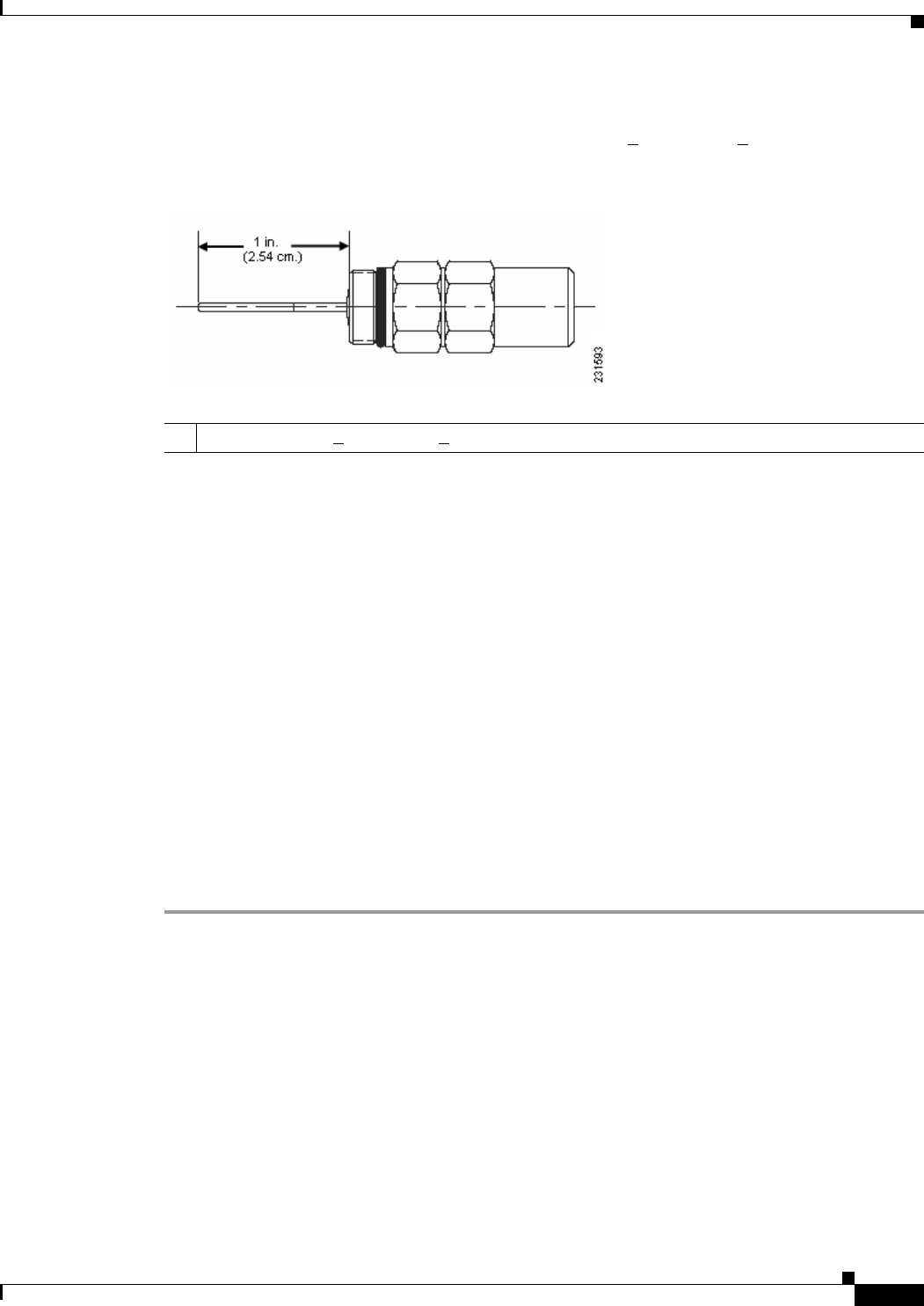
Step 9 Cut the cable stinger connector’s pin (see Figure 2-39) to 0.75 + 0.1 in. (1.91 + 0.25 cm).
Figure 2-39 Cable Stinger Connector Pin
Step 10 Insert the cable Stinger connector pin into the cable POC connector opening in the access point case.
Step 11 Screw the Stinger connector into the POC connector opening, and hand-tighten.
Step 12 Use an adjustable wrench to tighten the Stinger connector to6 to 7 ft lbs (8.1to 9.5 Nm).
Step 13 Use a Phillips screw driver to tighten the stinger set-screw on the RF splitter to 2.7 to 3.2 ft lbs
(3.66 to 4.34 Nm).
Step 14 Before connecting cable POC power to the access point, ensure that the antennas are attached to the
access point.
Step 15 Connect or attach the cable company’s POC cable to the Stinger connector according to their
specifications.
Step 16 Turn on cable POC power.
Step 17 Reinsert the RF splitter shunt.
Step 18 Check the cable modem’s Power and Cable LEDs and verify the cable modem receives power and
registers to the cable network. The Power LED (fifth LED from the hinge) is green to indicate power is
available.The Cable LED ( second LED from the hinge) should be blinking green to indicate scanning
the cable network and green to indicate registered on the cable network.
Step 19 Close the hinged cover (see the “Closing the Access Point Hinged Cover” section on page 2-39).
What to Do Next
When you power up a MAP that is not connected to a wired Ethernet, fiber-optic, or cable network to
the controller, the access point uses the Cisco Adaptive Wireless Path Protocol to bind to another MAP
with the best path to a RAP connected to the wired network to a controller. The access point sends a
discovery request when powered up. If you have configured the access point in the controller correctly,
the controller sends back a discovery response to the access point. When that happens, the access point
sends out a join request to the controller, and the controller responds with a join confirmation response.
Then the access point establishes an LWAPP connection to the controller and gets the shared secret
configured on the controller.
1Pin length is 0.75 + 0.1in. (1.91 + 0.25 cm).

REVIEW DRAFT—CISCO CONFIDENTIAL
2-66
Cisco Aironet 1520 Series Outdoor Mesh Access Point Hardware Installation Guide
OL-12632-03
Chapter 2 Mounting Instructions
Powering the Access Point
Refer to the Cisco Wireless LAN Controller Configuration Guide for more information on configuring,
monitoring, and operating your access points. The following lists some of the configuration settings you
might want to reconfigure:
• Selecting a backhaul channel when using the 4.9 MHz band
• Reconfiguring the bridge group name

CHAPTER
REVIEW DRAFT—CISCO CONFIDENTIAL
3-1
Cisco Aironet 1520 Series Outdoor Mesh Access Point Hardware Installation Guide
OL-12632-03
3
Troubleshooting
This chapter provides troubleshooting procedures for basic problems with the access point. For the most
up-to-date, detailed troubleshooting information, refer to the Cisco Technical Support and
Documentation website at the following URL:
http://www.cisco.com/en/US/products/hw/wireless/tsd_products_support_category_home.html
Sections in this chapter include:
• Guidelines for Using the Access Points, page 3-2
• Controller MAC Filter List, page 3-3
• Using DHCP Option 43, page 3-4
• Monitoring the Access Point LEDs, page 3-4
• Verifying Controller Association, page 3-5
• Cable Modem LEDs, page 3-7
• Connecting to the Access Point Locally, page 3-8
• Access Point Power Injector, page 3-9

REVIEW DRAFT—CISCO CONFIDENTIAL
3-2
Cisco Aironet 1520 Series Outdoor Mesh Access Point Hardware Installation Guide
OL-12632-03
Chapter 3 Troubleshooting
Guidelines for Using the Access Points
Guidelines for Using the Access Points
You should keep these guidelines in mind when you use the access points:
• The access point can only communicate with controllers and cannot operate independently.
• The access point does not support Wireless Domain Services (WDS) and cannot communicate with
WDS devices. However, the controller provides functionality equivalent to WDS when the access
point associates to it.
• The access points only supports Layer 3 LWAPP communications with the controllers.
In Layer 3 operation, the access point and the controller can be on the same or different subnets. The
access point communicates with the controller using standard IP packets. A Layer 3 access point on
a different subnet than the controller requires a DHCP server on the access point subnet and a route
to the controller. The route to the controller must have destination UDP ports 12222 and 12223 open
for LWAPP communications. The route to the primary, secondary, and tertiary controllers must
allow IP packet fragments.
• Before deploying your access points, ensure that the following has been done:
–
Your controllers are connected to switch ports that are configured as trunk ports.
–
Your access points are connected to switch ports that are configured as untagged access ports.
–
A DHCP server is reachable by your access points and has been configured with Option 43.
Option 43 provides the IP addresses of the management interfaces of your controllers.
Typically, a DHCP server can be configured on a Cisco switch.
–
Optionally a DNS server can be configured to enable CISCO-LWAPP-CONTROLLER.<local
domain> to resolve to the IP address of the management interface of your controller.
–
Your controllers are configured and reachable by the access points.
–
Your controllers are configured with the access point MAC addresses and the MAC filter list is
enabled.
–
Your switch must forward DHCP requests.
• The access point PoE-out port should be connected only to a single peripheral customer device, such
as a camera or sensor gateway. Cisco recommends that the PoE-out port not be connected to a switch
or hub.
• After the access points are associated to the controller, you should change the bridge group name
(BGN) from the default value. With the default BGN, the MAPs can potentially try to connect with
other mesh networks and slow down the convergence of the network.
Important Notes
Convergence Delays
During deployment, the access points can experience convergence delays due to various causes. The
following list identifies some operating conditions that can cause convergence delays:
• A RAP attempts to connect to a controller using any of the wired ports (cable, fiber-optic, PoE-in,
or PoE-out). If the wired ports are operational, the RAP can potentially spend several minutes on
each port prior to connecting to a controller.

REVIEW DRAFT—CISCO CONFIDENTIAL
3-3
Cisco Aironet 1520 Series Outdoor Mesh Access Point Hardware Installation Guide
OL-12632-03
Chapter 3 Troubleshooting
Controller MAC Filter List
• If a RAP is unable to connect to a controller over the wired ports, it attempts to connect using the
wireless network. This results in additional delays when multiple potential wireless paths are
available.
• If a MAP is unable to connect to a RAP using a wireless connection, it then attempts to connect using
any available wired port. The access point can potentially spend several minutes for each connection
method, before attempting the wireless network again.
Bridge Loop
The access point supports packet bridging between wired and wireless network connections. The same
network must never be connected to multiple wired ports on an access point or on two bridged access
points. A bridge loop causes network routing problems.
Controller DHCP Server
The controller DHCP server only assigns IP addresses to lightweight access points and wireless clients
associated to an access point. It does not assign an IP address to other devices, including Ethernet
bridging clients on the mesh access points.
MAP Data Traffic
If the signal on the access point backhaul channel has a high signal to noise ratio (not good), it is possible
for a MAP to connect to the controller but not be able to pass data traffic, such as pinging the access
point. This can occur because the default datarate for backhaul control packets is set to 6 Mbps, but the
default datarate for data traffic is 24 Mbps.
Controller MAC Filter List
Before activating your access point, you must ensure that the access point MAC address has been added
to the controller MAC filter list and that Mac Filter List is enabled.
Note The access point MAC address and barcode is located on the bottom of the unit. When two MAC
addresses are shown, use the top MAC address.
To view the MAC addresses added to the controller MAC filter list, you can use the controller CLI or
the controller GUI:
• Controller CLI—Use the show macfilter summary controller CLI command to view the MAC
addresses added to the controller filter list.
• Controller GUI—Log into your controller web interface using a web browser, and choose
SECURITY > AAA > MAC Filtering to view the MAC addresses added to the controller filter list.
REVIEW DRAFT—CISCO CONFIDENTIAL
3-4
Cisco Aironet 1520 Series Outdoor Mesh Access Point Hardware Installation Guide
OL-12632-03
Chapter 3 Troubleshooting
Using DHCP Option 43
Using DHCP Option 43
You can use DHCP Option 43 to provide a list of controller IP addresses to the access points, enabling
the access point to find and join a controller. Refer to the product documentation for your DHCP server
for instructions on configuring DHCP Option 43. For additional information, refer to the “Configuring
DHCP Option 43” section on page F-1.
Monitoring the Access Point LEDs
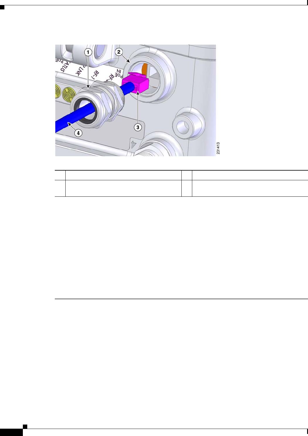
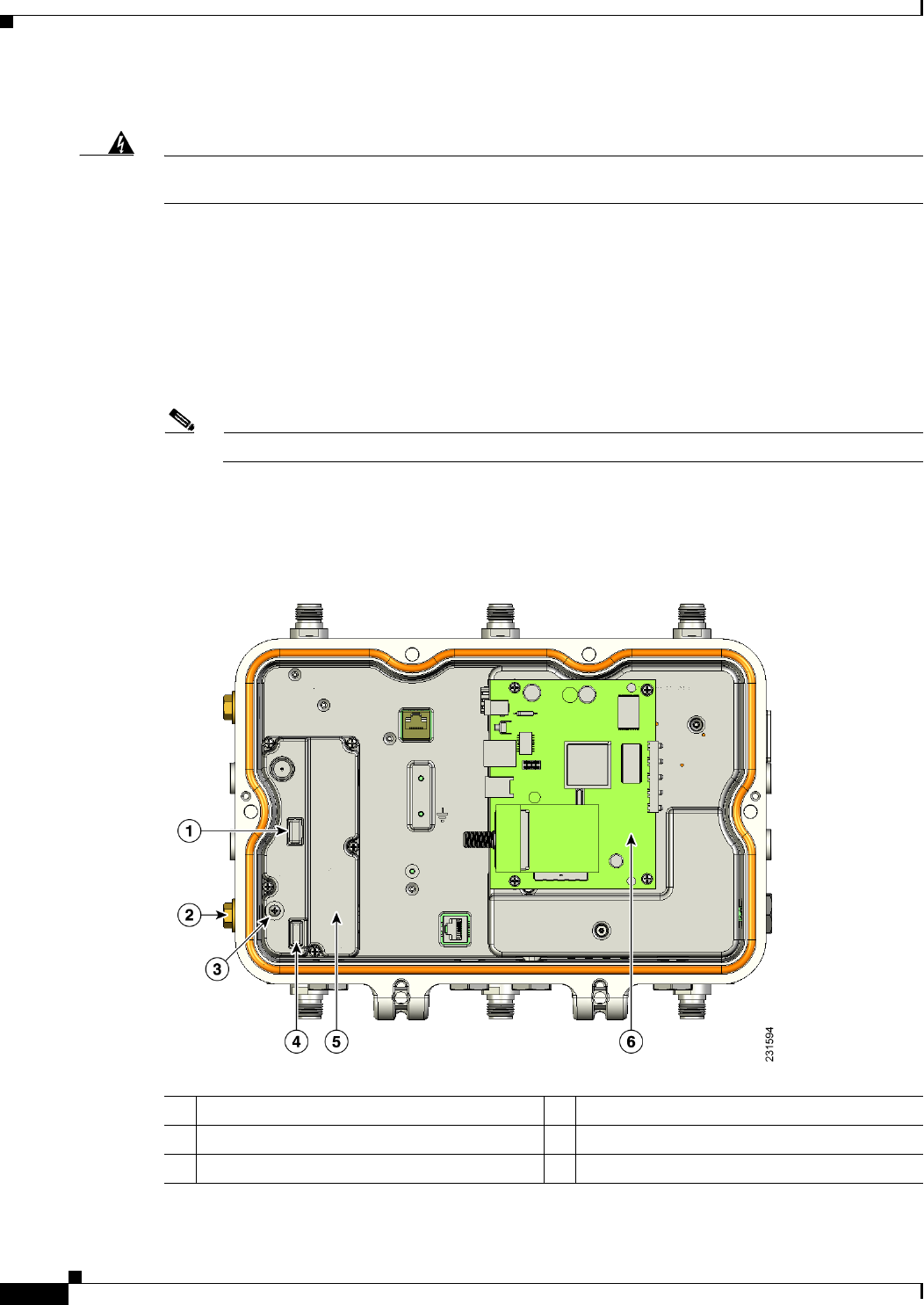
If your access point is not working properly, look at the LEDs on the bottom of the unit. You can use
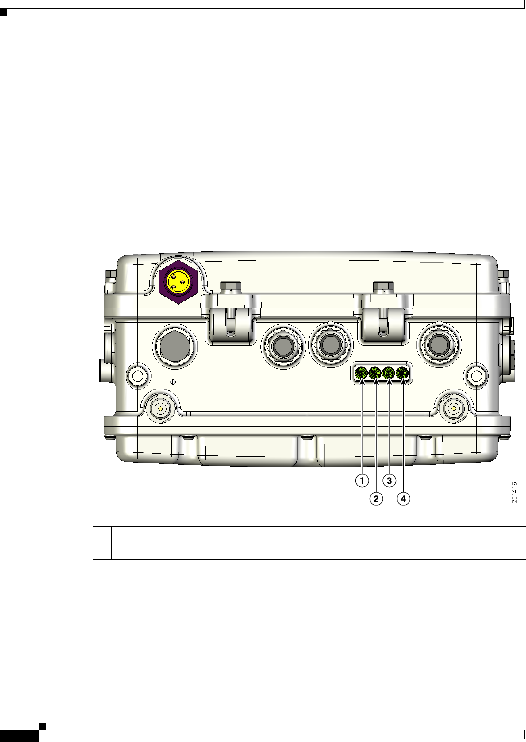
them to quickly assess the unit’s status. Figure 3-1 shows the location of the access point LEDs.
Figure 3-1 Access Point LEDs on the Bottom of the Unit
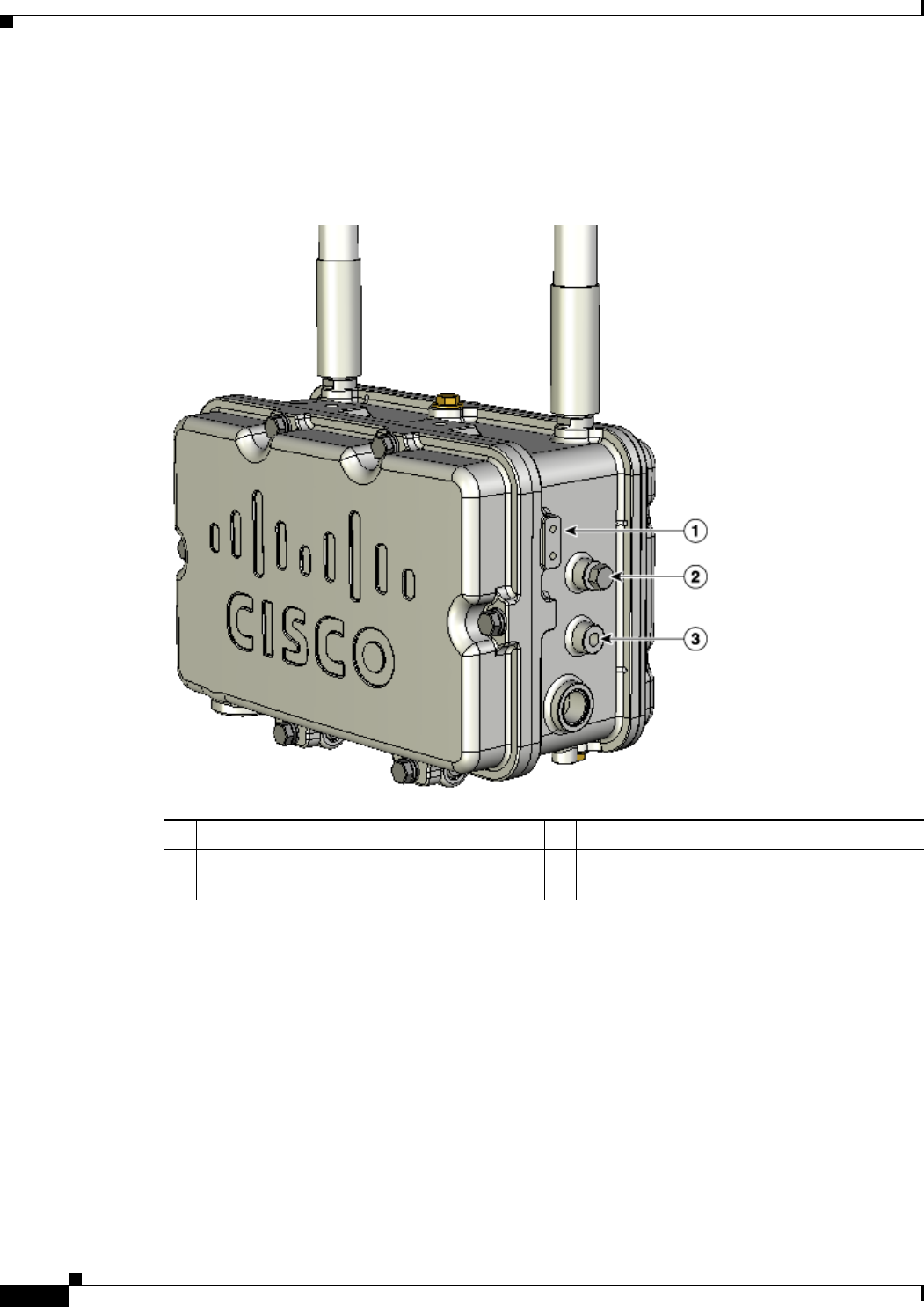
1Status LED—access point and software status 3RF-1 LED—802.11b/g radio status
2Uplink LED—Ethernet, cable, or fiber status 4RF-2 LED—802.11a radio status