Cisco Systems 102067 4.9GHz Radio Module User Manual 1520higb
Cisco Systems Inc 4.9GHz Radio Module 1520higb
Contents
- 1. Manual 1
- 2. Manual 2
- 3. Manual 3
Manual 3

REVIEW DRAFT—CISCO CONFIDENTIAL
3-5
Cisco Aironet 1520 Series Outdoor Mesh Access Point Hardware Installation Guide
OL-12632-03
Chapter 3 Troubleshooting
Verifying Controller Association
The access point LED signals are listed in Table 3-1.
Verifying Controller Association
To verify that your access point is associated to the controller, follow these steps:
Step 1 Log into your controller web interface using a web browser.
You can also use the controller CLI show ap summary command from the controller console port.
Step 2 Click Wireless, and verify that your access point MAC address is listed under Ethernet MAC.
Step 3 Log out of the controller, and close your web browser.
Ta b l e 3-1 Access Point LED Signals
LED Color1, 2
1. If all LEDs off, the access point has no power.
2. When the access point power supply is initially turned on, all LEDs are amber.
Meaning
Status Off –
Green Access point is operational.
Blinking green Download or upgrade of Cisco IOS image file in progress.
Amber Mesh neighbor access point discovery in progress.
Blinking amber Mesh authentication in progress.
Blinking red / green /amber LWAPP discovery in progress.
Red Firmware failure. Contact your support organization for assistance.
Uplink Off No physical connector present or the uplink port is not operational.
Green Uplink network is operational (cable, fiber optic, or Ethernet).
RF-1
(2.4-GHz radio)
Off Radio turned off.
Green Radio is operational.
Red Firmware failure. Contact your support organization for assistance.
RF-2
(5-GHz radio)
Off Radio turned off.
Green Radio is operational.
Red Firmware failure. Contact your support organization for assistance.

REVIEW DRAFT—CISCO CONFIDENTIAL
3-6
Cisco Aironet 1520 Series Outdoor Mesh Access Point Hardware Installation Guide
OL-12632-03
Chapter 3 Troubleshooting
Changing the Bridge Group Name
Changing the Bridge Group Name
The bridge group name (BGN) controls the association of the access points to a RAP. BGNs can be used
to logically group the radios to avoid different networks on the same channel from communicating with
each other. This setting is also useful if you have more than one RAP in your network in the same area.
If you have two RAPs in your network in the same area (for more capacity), we recommend that you
configure the two RAPs with different BGNs and on different channels.
The BGN is a string of ten characters maximum. A factory-set bridge group name (NULL VALUE) is
assigned during manufacturing. It is not visible to you, but allows new access point radios to join a
network of new access points. The BGN can be reconfigured from the Controller CLI and GUI. After
configuring the BGN, the access point reboots.
After the access points are deployed and associated to the controller, the BGN should be changed from
the default value to prevent the MAPs from attempting to associate to other mesh networks.
The BGN should be configured very carefully on a live network. You should always start with the most
distant access point (last node) from the RAP and move towards the RAP. If you start configuring the
BGN in a different location, then the access points beyond this point (farther away) are dropped, as they
have a different BGN.
To configure the BGN for the access points using the controller GUI, follow these steps:
Step 1 Log into your controller using a web browser.
Step 2 Click Wireless. When access points associates to the controller, the access point’s name appears in the
AP Name list.
Step 3 Click on an access point’s name.
Step 4 Find the Mesh Information section, and enter the new BGN in the Bridge Group Name field.
Step 5 Click Apply.
Step 6 Repeat Steps 2 through 5 for each access point.
Step 7 Log out from your controller, and close your web browser.
REVIEW DRAFT—CISCO CONFIDENTIAL
3-7
Cisco Aironet 1520 Series Outdoor Mesh Access Point Hardware Installation Guide
OL-12632-03
Chapter 3 Troubleshooting
Cable Modem LEDs
Cable Modem LEDs
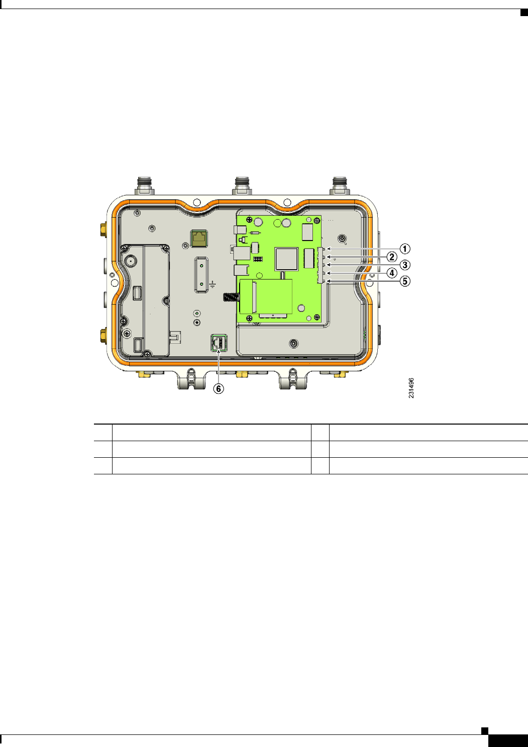
The internal cable modem in the access point cable configuration has five LEDs (see Figure 3-2). To
view the cable modem LEDs, you must open the access point hinged cover (refer to the “Opening the
Access Point Hinged Cover” section on page 2-38). After viewing the LEDs, you must close the hinged
cover (refer to the “Closing the Access Point Hinged Cover” section on page 2-39).
Figure 3-2 Cable Modem LEDs and Console Port Location
1Power LED 4Cable LED
2Receive data LED 5PC LED
3Send data LED 6Console port connector1
1. The console port is available on all access point configurations.

REVIEW DRAFT—CISCO CONFIDENTIAL
3-8
Cisco Aironet 1520 Series Outdoor Mesh Access Point Hardware Installation Guide
OL-12632-03
Chapter 3 Troubleshooting
Connecting to the Access Point Locally
Table 3-2 describes the status information provided by the cable modem LEDs.
Connecting to the Access Point Locally
If you need to monitor the access point locally (without connecting the access point to a wired LAN),
you can connect a PC to its console port using a DB-9 to RJ-45 serial cable.
Note The console port should only be used for debugging in a lab environment.
Follow these steps to open the CLI by connecting to the access point console port:
Step 1 Open the hinged cover of the access point (see “Opening the Access Point Hinged Cover” section on
page 2-38 for instructions).
Connect a nine-pin, female DB-9 to RJ-45 serial cable to the RJ-45 console port on the access point and
to the COM port on a computer (see Figure 3-2 for the console port location).
Note The Cisco part number for the DB-9 to RJ-45 serial cable is AIR-CONCAB1200. Browse to
http://www.cisco.com/go/marketplace to order a serial cable.
Step 2 Set up a terminal emulator program on your PC to communicate with the access point. Use the following
settings for the terminal emulator connection: 9600 baud, 8 data bits, no parity, 1 stop bit, and no flow
control.
Ta b l e 3-2 Cable LED Status Information
LEDs Description
Power Green indicates power is available.
Receive data Blinking green indicates that the cable modem is receiving data from the
cable network.
Send data Blinking green indicates that the cable modem is sending data to the cable
network.
Cable Green indicates that the cable modem is registered on the cable network and
is operational.
Blinking green indicates that the cable modem is performing one of these
operations:
• Booting up.
• Scanning the network and attempting to register.
• Lost registration on the cable network and attempting to reregister.
PC Green indicates that an Ethernet carrier has been detected.
Blinking green indicates that data is been transferred between the PC and
the cable modem.
REVIEW DRAFT—CISCO CONFIDENTIAL
3-9
Cisco Aironet 1520 Series Outdoor Mesh Access Point Hardware Installation Guide
OL-12632-03
Chapter 3 Troubleshooting
Access Point Power Injector
Step 3 When finished, remove your serial cable, and close the hinged cover (see the “Closing the Access Point
Hinged Cover” section on page 2-39 for instructions).
Access Point Power Injector
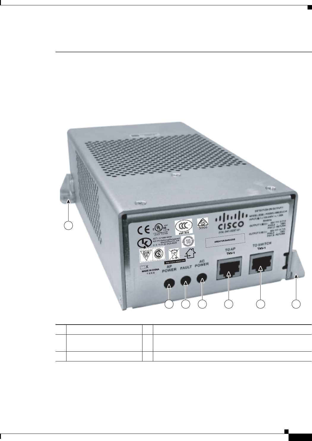
The power injector (AIR-PWRINJ1500-2=) has three LEDs on the front end of the case (see Figure 3-3).
Figure 3-3 Power Injector Connectors and LEDs
1Mounting tab 4AC power LED
2Access point power LED 5Ethernet connector (RJ-45) to access point
(10/100/1000BASE-T)
3Fault LED 6Ethernet connector (RJ-45) to switch (10/100/1000BASE-T)
211485
231484
1
12 3 4 5 6

REVIEW DRAFT—CISCO CONFIDENTIAL
3-10
Cisco Aironet 1520 Series Outdoor Mesh Access Point Hardware Installation Guide
OL-12632-03
Chapter 3 Troubleshooting
Access Point Power Injector
Monitoring the Power Injector LEDs
You can use the AP Power, Fault, and AC Power LEDs to check the power injector status. The LEDs
provide the following status information:
• AP Power LED—Turns solid green after successful discovery; indicates that power injector is
supplying power to the access point.
• Fault LED—Turns solid red when a fault occurs during discovery mode or power-up. Check
Ethernet cables and connections before contacting your support organization for assistance.
• AC Power LED—Turns solid green when power injector is receiving AC power and is ready to
provide power to the access point.

CHAPTER
REVIEW DRAFT—CISCO CONFIDENTIAL
4-1
Cisco Aironet 1520 Series Outdoor Mesh Access Point Hardware Installation Guide
OL-12632-03
4
Installing or Replacing the Backup Battery
This chapter describes the procedures to install or replace the backup battery in the access point. These
sections are included in this chapter:
• Before Beginning the Installation or Replacement, page 4-2
• Opening the Access Point Radio Cover, page 4-3
• Removing a Backup Battery, page 4-4
• Installing a New Backup Battery, page 4-5
• Connecting the Backup Battery Cable and Closing the Radio Cover, page 4-6

REVIEW DRAFT—CISCO CONFIDENTIAL
4-2
Cisco Aironet 1520 Series Outdoor Mesh Access Point Hardware Installation Guide
OL-12632-03
Chapter 4 Installing or Replacing the Backup Battery
Before Beginning the Installation or Replacement
Before Beginning the Installation or Replacement
The backup battery is located internal to the access point and attached to the radio cover. The backup
battery cannot be installed or replaced in an outdoor environment, you must use a static protected work
surface within an indoor environment.
Warning
Only trained and qualified personnel should be allowed to install, replace, or service this equipment.
Statement 1030
Caution ESD can damage the internal components of the access point. It is recommended that the backup battery
installation or replacement procedures be performed by an ESD trained service technician at an
ESD-protected workstation.
The following operations summarize the backup battery installation or replacement procedure:
1. If the access point has been deployed, deactivate all power sources, remove all cables, remove the
access point.
2. Follow standard electrostatic discharge (ESD) procedures.
3. Place the access point on an indoor ESD-protected work surface.
4. Open the access point's radio cover.
5. If applicable, remove the defective backup battery.
6. Install the new backup battery.
7. Connect the backup battery cable.
8. Close the access point’s radio cover.
9. Deploy your access point.
REVIEW DRAFT—CISCO CONFIDENTIAL
4-3
Cisco Aironet 1520 Series Outdoor Mesh Access Point Hardware Installation Guide
OL-12632-03
Chapter 4 Installing or Replacing the Backup Battery
Opening the Access Point Radio Cover
Opening the Access Point Radio Cover
Follow these procedures to open the access point radio cover:
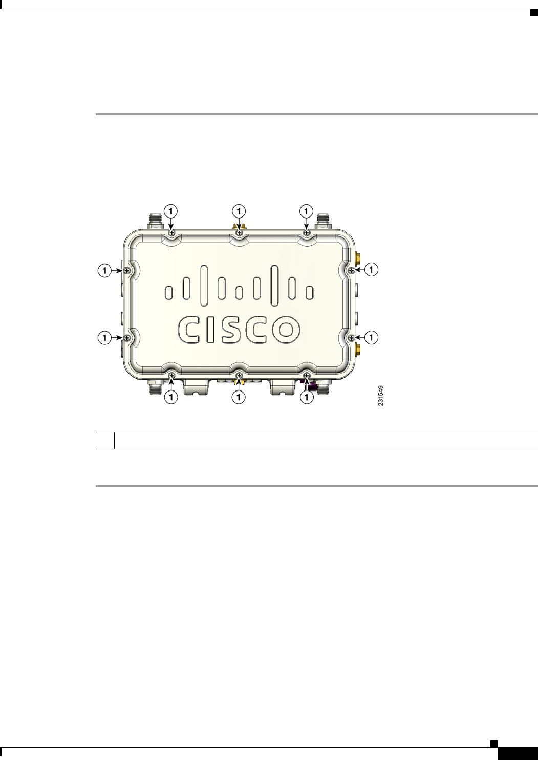
Step 1 Position the access point with the cover attached with hex bolts facing down.
Step 2 Use a #8 Torx screwdriver to unscrew all the Torx screws on the access point cover, but do not attempt
to remove the screws (see Figure 4-1).
Figure 4-1 Access Point Radio Cover Screws
Step 3 Carefully open the cover.
1Radio cover Torx screws
REVIEW DRAFT—CISCO CONFIDENTIAL
4-4
Cisco Aironet 1520 Series Outdoor Mesh Access Point Hardware Installation Guide
OL-12632-03
Chapter 4 Installing or Replacing the Backup Battery
Removing a Backup Battery
Removing a Backup Battery
Follow these steps to remove a backup battery:
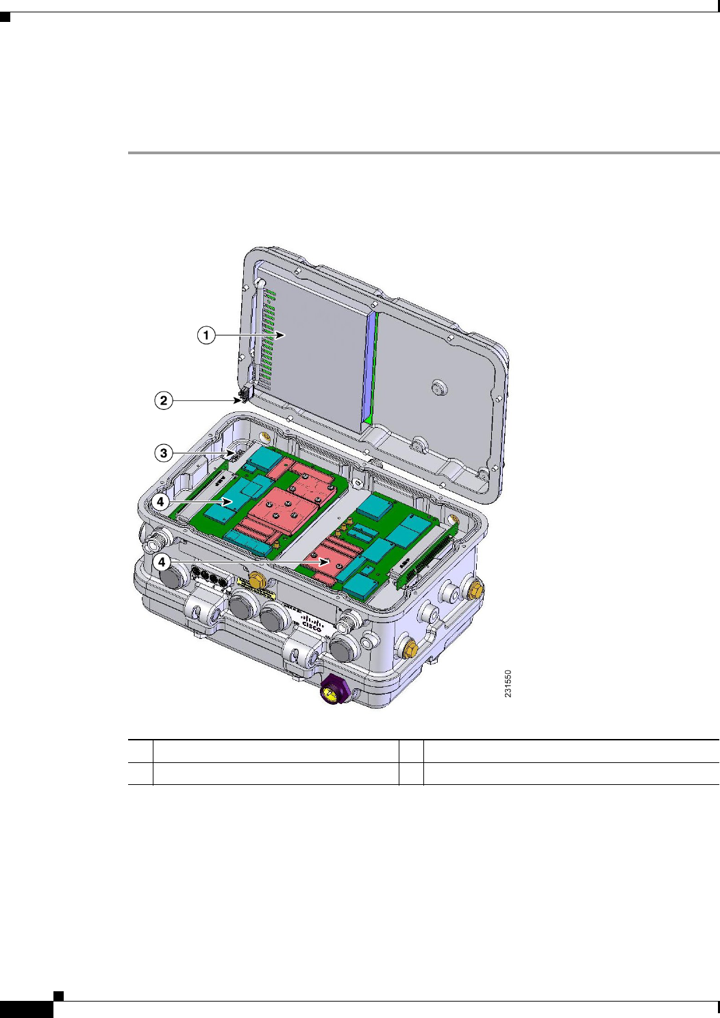
Step 1 While holding the access point cover open, carefully disconnect the backup battery cable from the
internal connector (see Figure 4-2). Be careful not to touch the radio board components.
Figure 4-2 Battery Backup Location
Step 2 Carefully place the cover onto your static-protected table.
1Backup battery 3Internal connector for the backup battery cable
2Backup battery cable 4Radio boards (Do not touch)
REVIEW DRAFT—CISCO CONFIDENTIAL
4-5
Cisco Aironet 1520 Series Outdoor Mesh Access Point Hardware Installation Guide
OL-12632-03
Chapter 4 Installing or Replacing the Backup Battery
Installing a New Backup Battery
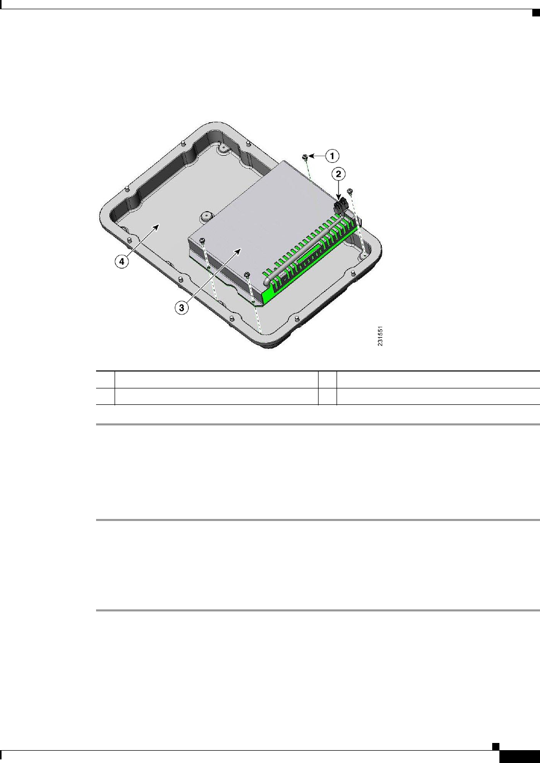
Step 3 Use a phillips screw driver to remove the four screws attaching the backup battery to the cover
(see Figure 4-3).
Figure 4-3 Backup Battery Screws
Installing a New Backup Battery
Follow these steps to install a new backup battery into your access point:
Step 1 Carefully orient your new backup battery as shown in Figure 4-3 over the access point radio cover.
Step 2 Position the backup battery over the four screw holes in the radio cover.
Step 3 Use the four supplied screws to attach the backup battery to the radio cover and tighten to 5.5 to 6.5 in.
lbs (0.62 to 0.73 Nm).
Step 4 Position and bend the backup battery cable as shown in Figure 4-3.
1Battery backup screws (4 places) 3Backup battery
2Battery backup cable and connector 4Access point radio cover

REVIEW DRAFT—CISCO CONFIDENTIAL
4-6
Cisco Aironet 1520 Series Outdoor Mesh Access Point Hardware Installation Guide
OL-12632-03
Chapter 4 Installing or Replacing the Backup Battery
Connecting the Backup Battery Cable and Closing the Radio Cover
Connecting the Backup Battery Cable and Closing the Radio
Cover
Follow these steps to connect the backup battery cable and close the access point radio cover:
Step 1 Carefully position the access point radio cover over the access point as shown in Figure 4-2.
Step 2 Hold the radio cover upright while placing the edge of the radio cover on the top edge of the access point.
Step 3 Carefully push the backup battery cable connector into the internal battery connector (see Figure 4-2).
Step 4 Close the radio cover, while being careful not to pinch the backup battery cable.
Step 5 Use a Phillips screwdriver to partially tighten each cover screw in the tightening sequence shown in
Figure 4-4. Tighten each screw to 11 to 12 in. lbs (1.24 to 1.36 Nm).
Step 6 Repeat Step 5 using the same tightening sequence to fully tighten each screw to 22 to 24 in. lbs
(2.49 to 2.71 Nm).
Figure 4-4 Radio Cover Screw Tightening Sequence
What to do Next
After you have completed the backup battery procedures, your access point is ready to be deployed.
Carefully read and follow the safety and installation guidelines and instructions contained in the
“Mounting Instructions” section on page 2-1 or the mounting instructions document that shipped with
your access point.

REVIEW DRAFT—CISCO CONFIDENTIAL
A-1
Cisco Aironet 1520 Series Outdoor Mesh Access Point Hardware Installation Guide
OL-12632-03
APPENDIX
A
Translated Safety Warnings
For translated safety warnings, refer to the safety warning document that shipped with your access point or
that is available on Cisco.com.
To browse to the document on Cisco.com, follow these steps:
Step 1 Click this link to the Cisco Wireless documentation home page:
Step 2 http://www.cisco.com/en/US/products/hw/wireless/index.html
Step 3 Click Cisco Aironet 1520 Series listed under Outdoor Wireless.
Step 4 Click Install and Upgrade.
Step 5 Click Install and Upgrade Guides.
Step 6 Click Translated Safety Warnings for Cisco Aironet 1520G Series Outdoor Mesh Access Points.

REVIEW DRAFT—CISCO CONFIDENTIAL
A-2
Cisco Aironet 1520 Series Outdoor Mesh Access Point Hardware Installation Guide
OL-12632-03
Appendix A Translated Safety Warnings

REVIEW DRAFT—CISCO CONFIDENTIAL
B-1
Cisco Aironet 1520 Series Outdoor Mesh Access Point Hardware Installation Guide
OL-12632-03
APPENDIX
B
Declarations of Conformity and
Regulatory Information
This appendix provides declarations of conformity and regulatory information for the
Cisco Aironet 1520 series lightweight outdoor mesh access point.
This appendix contains the following sections:
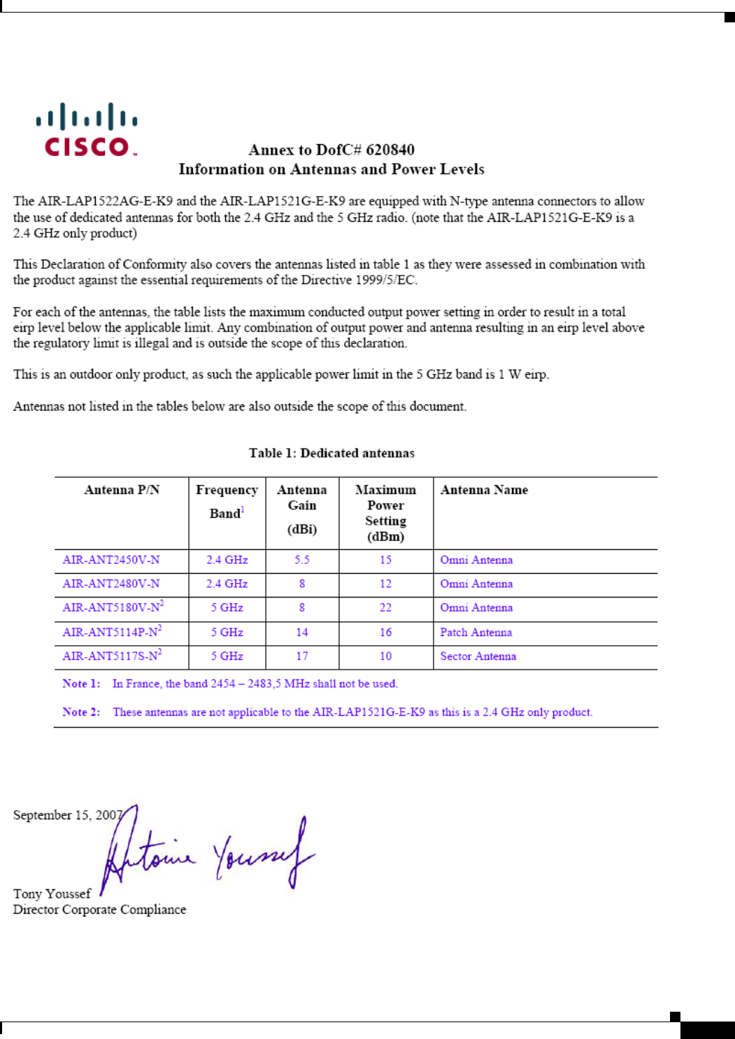
• Manufacturers Federal Communication Commission Declaration of Conformity Statement for
Model LAP1522, page B-2
• Declaration of Conformity Statements for Model LAP1522, page B-10
• Manufacturers Federal Communication Commission Declaration of Conformity Statement for
Model LAP1524, page B-12
REVIEW DRAFT—CISCO CONFIDENTIAL
B-2
Cisco Aironet 1520 Series Outdoor Mesh Access Point Hardware Installation Guide
OL-12632-03
Appendix B Declarations of Conformity and Regulatory Information
Manufacturers Federal Communication Commission Declaration of Conformity Statement for Model LAP1522
Manufacturers Federal Communication Commission
Declaration of Conformity Statement for Model LAP1522
Model:
AIR-LAP1522AG-A-K9
FCC Certification number:
Manufacturer:
Cisco Systems, Inc.
170 West Tasman Drive
San Jose, CA 95134-1706
USA
This device complies with Part 15 rules. Operation is subject to the following two conditions:
1. This device may not cause harmful interference, and
2. This device must accept any interference received, including interference that may cause undesired
operation.
This equipment has been tested and found to comply with the limits of a Class B digital device, pursuant
to Part 15 of the FCC Rules. These limits are designed to provide reasonable protection against harmful
interference when the equipment is operated in a residential environment. This equipment generates,
uses, and radiates radio frequency energy, and if not installed and used in accordance with the
instructions, may cause harmful interference. However, there is no guarantee that interference will not
occur. If this equipment does cause interference to radio or television reception, which can be
determined by turning the equipment off and on, the user is encouraged to correct the interference by
one of the following measures:
• Reorient or relocate the receiving antenna.
• Increase separation between the equipment and receiver.
• Connect the equipment to an outlet on a circuit different from which the receiver is connected.
• Consult the dealer or an experienced radio/TV technician.
Caution The Part 15 radio device operates on a non-interference basis with other devices operating at this
frequency when using Cisco-supplied antennas. Any changes or modification to the product not
expressly approved by Cisco could void the user’s authority to operate this device.
Tested To Comply
With FCC Standards
FOR HOME OR OFFICE USE
AIR-RM1520G-A-K9: LDK102064
AIR-RM1520A-A-K9: LDK102063
REVIEW DRAFT—CISCO CONFIDENTIAL
B-3
Cisco Aironet 1520 Series Outdoor Mesh Access Point Hardware Installation Guide
OL-12632-03
Appendix B Declarations of Conformity and Regulatory Information
Manufacturers Federal Communication Commission Declaration of Conformity Statement for Model LAP1522
Caution To meet regulatory restrictions, the access point must be professionally installed.
Note The use of the 4.9-GHz band requires a license and may be used only by qualified Public Safety
operators as defined in section 90.20 of the FCC rules.
VCCI Statement for Japan
Department of Communications—Canada
IC Certification Number:
Canadian Compliance Statement
This Class B Digital apparatus meets all the requirements of the Canadian Interference-Causing
Equipment Regulations.
Cet appareil numerique de la classe B respecte les exigences du Reglement sur le material broilleur du
Canada.
This device complies with Class B Limits of Industry Canada. Operation is subject to the following two
conditions:
1. This device may not cause harmful interference, and
2. This device must accept any interference received, including interference that may cause undesired
operation.
Cisco’s access points are certified to the requirements of RSS-210 issue 5, RSP 100, and RSS 102 for
spread spectrum devices.
Warning
This is a Class B product based on the standard of the Voluntary Control Council for Interference from
Information Technology Equipment (VCCI). If this is used near a radio or television receiver in a
domestic environment, it may cause radio interference. Install and use the equipment according to
the instruction manual.
AIR-RM1520G-A-K9: 2461B-102064
AIR-RM1520A-A-K9: 2461B-102063

REVIEW DRAFT—CISCO CONFIDENTIAL
B-4
Cisco Aironet 1520 Series Outdoor Mesh Access Point Hardware Installation Guide
OL-12632-03
Appendix B Declarations of Conformity and Regulatory Information
Manufacturers Federal Communication Commission Declaration of Conformity Statement for Model LAP1522
Declaration of Conformity for RF Exposure
This access point product has been found to be compliant to the requirements set forth in CFR 47
Section 1.1307 addressing RF Exposure from radio frequency devices as defined in Evaluating
Compliance with FCC Guidelines for Human Exposure to Radio Frequency Electromagnetic Fields.T he
antennas should be positioned more than 6.56 feet (2 meters) from your body or nearby persons.
This access point is also compliant to EN 50835 for RF exposure.
European Community, Switzerland, Norway, Iceland, and Liechtenstein
Lightweight Access Point Models:
AIR-LAP1522G-E-K9
AIR-LAP1522AG-E-K9
REVIEW DRAFT—CISCO CONFIDENTIAL
B-5
Cisco Aironet 1520 Series Outdoor Mesh Access Point Hardware Installation Guide
OL-12632-03
Appendix B Declarations of Conformity and Regulatory Information
Manufacturers Federal Communication Commission Declaration of Conformity Statement for Model LAP1522
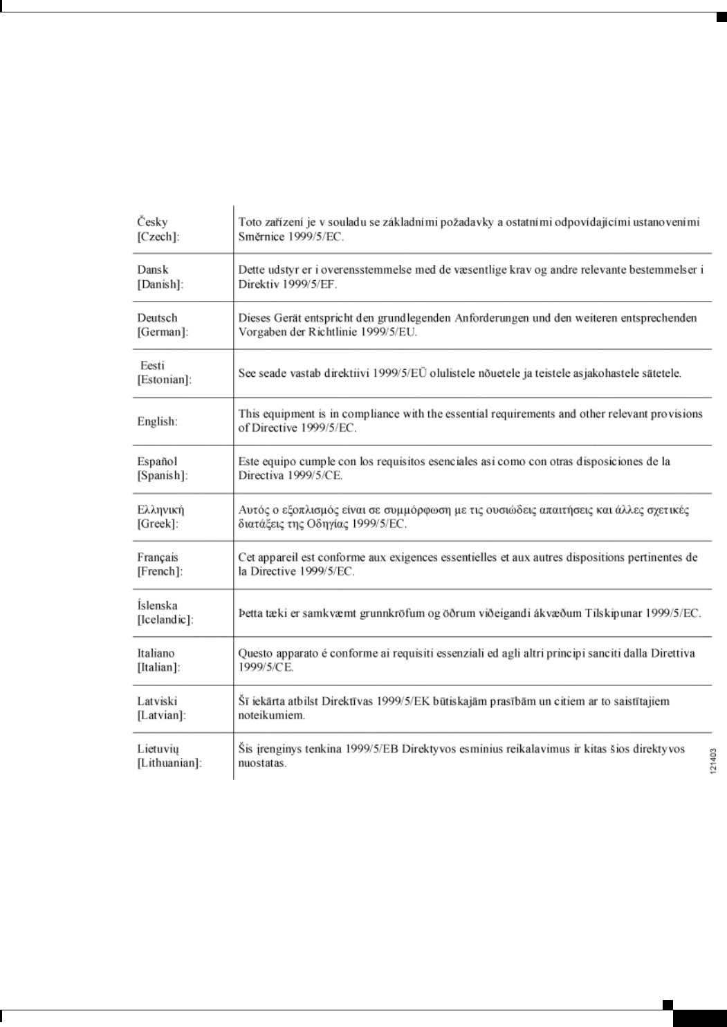
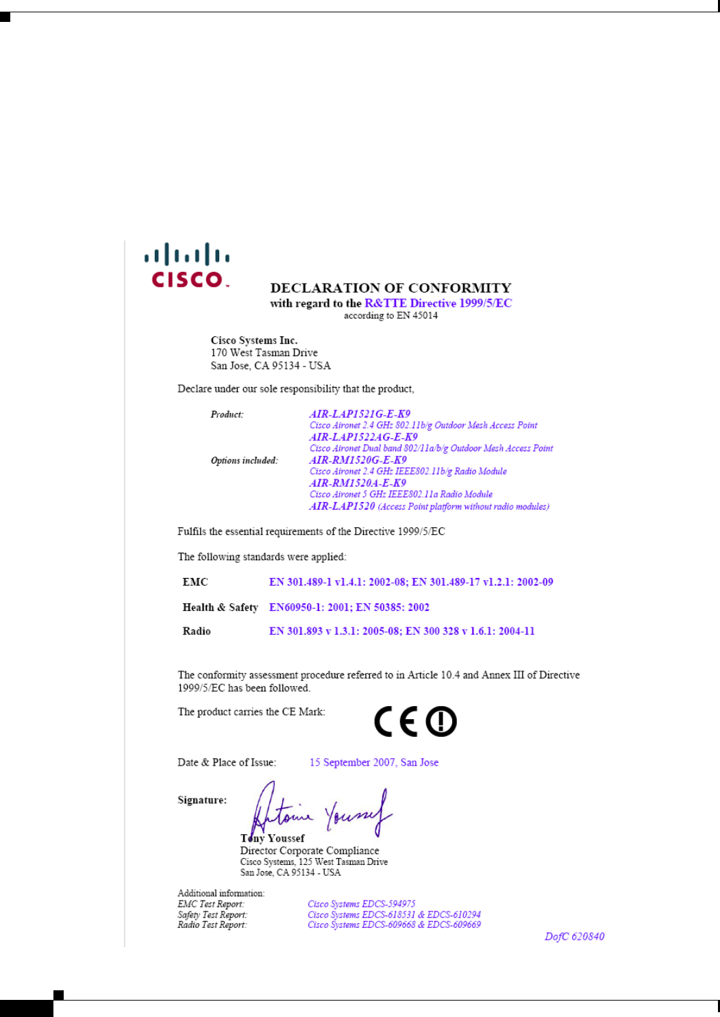
Declaration of Conformity with Regard to the 1999/5/EC (R&TTE Directive)
This declaration is only valid for configurations (combinations of software, firmware, and hardware)
provided and supported by Cisco Systems. The use of software or firmware not provided and supported
by Cisco Systems may result in the equipment no longer being compliant with the regulatory
requirements.
REVIEW DRAFT—CISCO CONFIDENTIAL
B-6
Cisco Aironet 1520 Series Outdoor Mesh Access Point Hardware Installation Guide
OL-12632-03
Appendix B Declarations of Conformity and Regulatory Information
Manufacturers Federal Communication Commission Declaration of Conformity Statement for Model LAP1522
This device complies with the EMC requirements (EN 60601-1-2) of the Medical Directive 93/42/EEC.
For 2.4 GHz radios, the following standards were applied:
• Radio: EN 300.328-1, EN 300.328-2
• EMC: EN 301.489-1, EN 301.489-17
• Safety: EN 60950
Note This equipment is intended to be used in all EU and EFTA countries. Outdoor use may be restricted to
certain frequencies and/or may require a license for operation. For more details, contact Cisco Corporate
Compliance.

REVIEW DRAFT—CISCO CONFIDENTIAL
B-7
Cisco Aironet 1520 Series Outdoor Mesh Access Point Hardware Installation Guide
OL-12632-03
Appendix B Declarations of Conformity and Regulatory Information
Manufacturers Federal Communication Commission Declaration of Conformity Statement for Model LAP1522
For 54 Mbps, 5 GHz access points, the following standards were applied:
• Radio: EN 301.893
• EMC: EN 301.489-1, EN 301.489-17
• Safety: EN 60950
The following CE mark is affixed to the access point with a 2.4 GHz radio and a 54 Mbps, 5 GHz radio:
Declaration of Conformity for RF Exposure
The radio has been found to be compliant to the requirements set forth in CFR 47 Sections 2.1091, and
15.247 (b) (4) addressing RF Exposure from radio frequency devices as defined in Evaluating
Compliance with FCC Guidelines for Human Exposure to Radio Frequency Electromagnetic Fields. The
equipment should be installed more than 20 cm (7.9 in.) from your body or nearby persons.
The access point must be installed to maintain a minimum 20 cm (7.9 in.) co-located separation distance
from other FCC approved indoor/outdoor antennas used with the access point. Any antennas or
transmitters not approved by the FCC cannot be co-located with the access point. The access point’s
co-located 2.4 GHz and 5 GHz integrated antennas support a minimum separation distance of
8 cm (3.2 in.) and are compliant with the applicable FCC RF exposure limit when transmitting
simultaneously.
Note Dual antennas used for diversity operation are not considered co-located.
Guidelines for Operating Cisco Aironet Access Points in Japan
This section provides guidelines for avoiding interference when operating Cisco Aironet access points
in Japan. These guidelines are provided in both Japanese and English.
Lightweight Access Point Models:
AIR-LAP1522G-P-K9
AIR-LAP1522AG-P-K9
REVIEW DRAFT—CISCO CONFIDENTIAL
B-8
Cisco Aironet 1520 Series Outdoor Mesh Access Point Hardware Installation Guide
OL-12632-03
Appendix B Declarations of Conformity and Regulatory Information
Manufacturers Federal Communication Commission Declaration of Conformity Statement for Model LAP1522
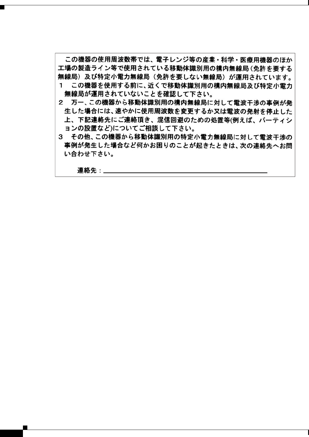
Japanese Translation
English Translation
This equipment operates in the same frequency bandwidth as industrial, scientific, and medical devices
such as microwave ovens and mobile object identification (RF-ID) systems (licensed premises radio
stations and unlicensed specified low-power radio stations) used in factory production lines.
1. Before using this equipment, make sure that no premises radio stations or specified low-power radio
stations of RF-ID are used in the vicinity.
2. If this equipment causes RF interference to a premises radio station of RF-ID, promptly change the
frequency or stop using the device; contact the number below and ask for recommendations on
avoiding radio interference, such as setting partitions.
3. If this equipment causes RF interference to a specified low-power radio station of RF-ID, contact
the number below.
Contact Number: 03-5549-6500
Administrative Rules for Cisco Aironet Access Points in Taiwan
This section provides administrative rules for operating Cisco Aironet access points in Taiwan. The rules
are provided in both Chinese and English.
03-5549-6500
43768
REVIEW DRAFT—CISCO CONFIDENTIAL
B-9
Cisco Aironet 1520 Series Outdoor Mesh Access Point Hardware Installation Guide
OL-12632-03
Appendix B Declarations of Conformity and Regulatory Information
Manufacturers Federal Communication Commission Declaration of Conformity Statement for Model LAP1522
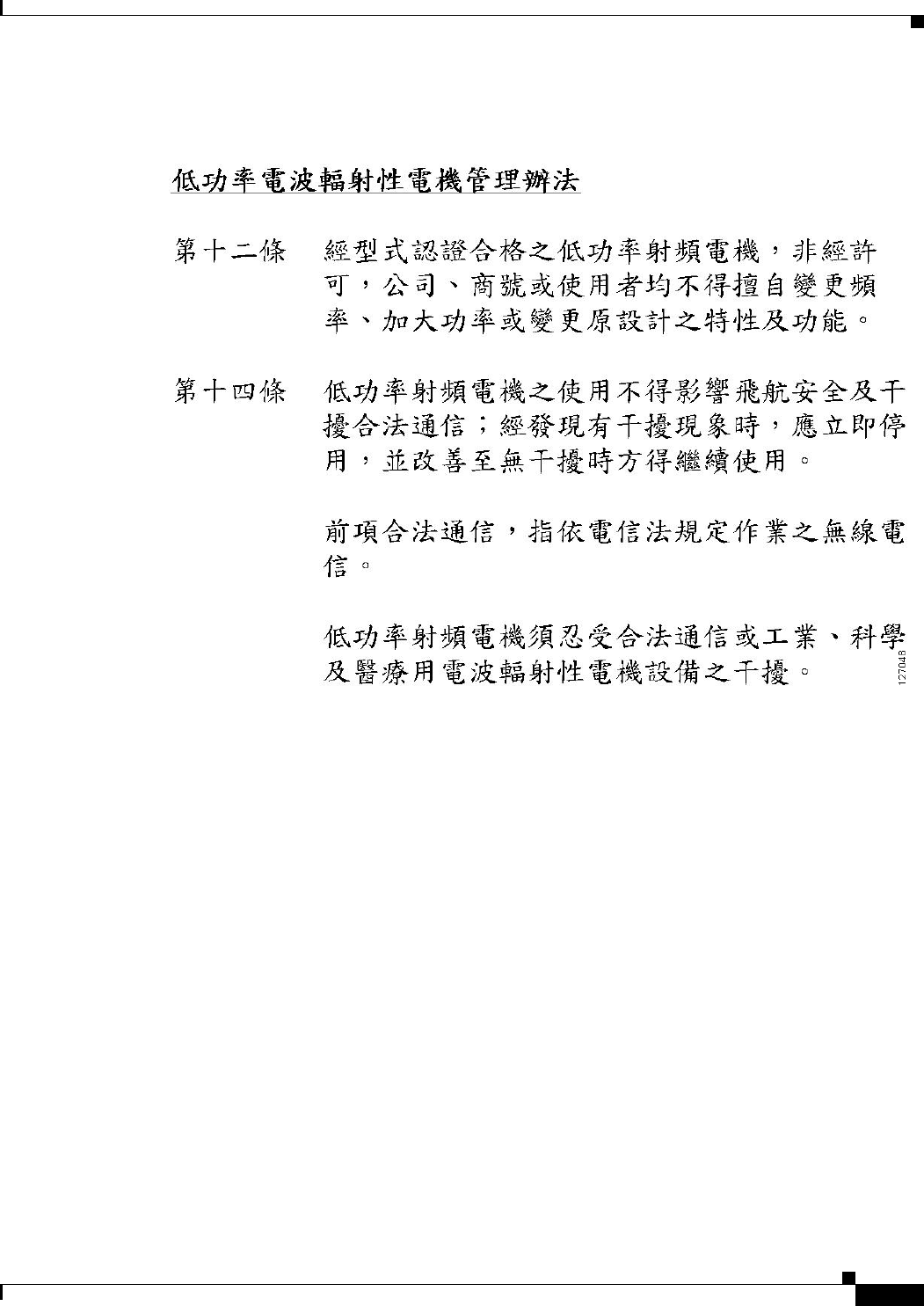
Chinese Translation
English Translation
Administrative Rules for Low-power Radio-Frequency Devices
Article 12
For those low-power radio-frequency devices that have already received a type-approval, companies,
business units or users should not change its frequencies, increase its power or change its original
features and functions.
Article 14
The operation of the low-power radio-frequency devices is subject to the conditions that no harmful
interference is caused to aviation safety and authorized radio station; and if interference is caused, the
user must stop operating the device immediately and can't re-operate it until the harmful interference is
clear.
The authorized radio station means a radio-communication service operating in accordance with the
Communication Act.
The operation of the low-power radio-frequency devices is subject to the interference caused by the
operation of an authorized radio station, by another intentional or unintentional radiator, by industrial,
scientific and medical (ISM) equipment, or by an incidental radiator.
REVIEW DRAFT—CISCO CONFIDENTIAL
B-10
Cisco Aironet 1520 Series Outdoor Mesh Access Point Hardware Installation Guide
OL-12632-03
Appendix B Declarations of Conformity and Regulatory Information
Declaration of Conformity Statements for Model LAP1522
Declaration of Conformity Statements for Model LAP1522
All the Declaration of Conformity statements related to this product can be found at the following URL:
http://www.ciscofax.com
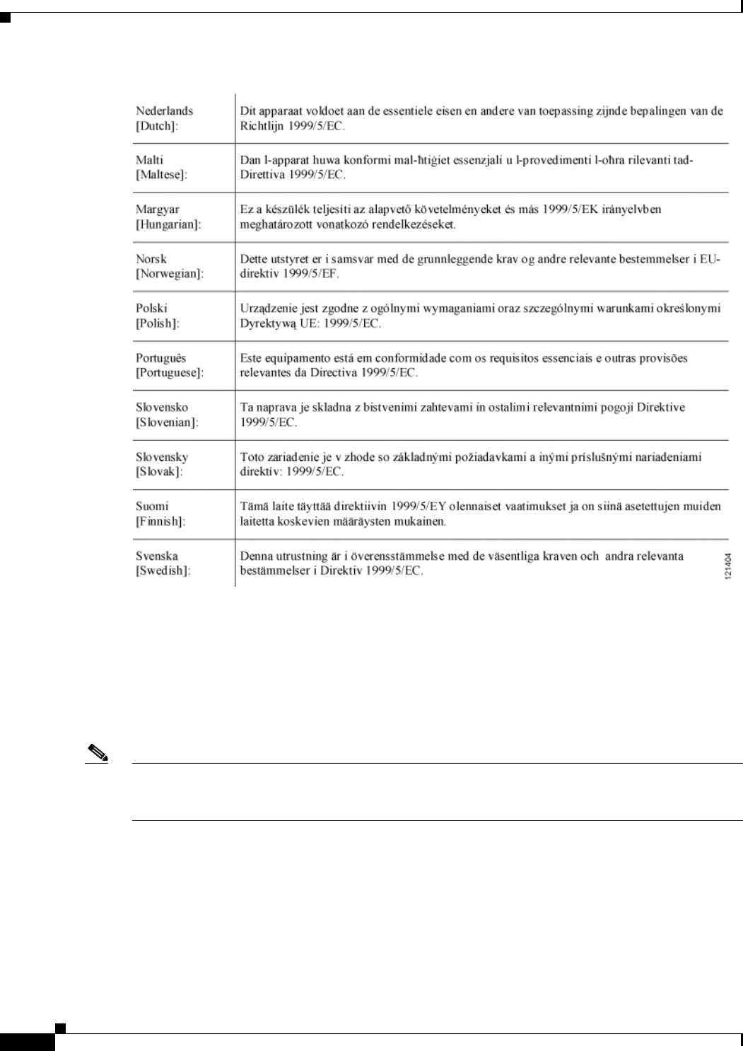
Declaration of Conformity Statements for European Union Countries
REVIEW DRAFT—CISCO CONFIDENTIAL
B-11
Cisco Aironet 1520 Series Outdoor Mesh Access Point Hardware Installation Guide
OL-12632-03
Appendix B Declarations of Conformity and Regulatory Information
Declaration of Conformity Statements for Model LAP1522

REVIEW DRAFT—CISCO CONFIDENTIAL
B-12
Cisco Aironet 1520 Series Outdoor Mesh Access Point Hardware Installation Guide
OL-12632-03
Appendix B Declarations of Conformity and Regulatory Information
Manufacturers Federal Communication Commission Declaration of Conformity Statement for Model LAP1524
Manufacturers Federal Communication Commission
Declaration of Conformity Statement for Model LAP1524
This section provides declarations of conformity and regulatory information for the
Cisco Aironet 1524 Series Outdoor Mesh Access Point.
Overview
The Cisco Aironet 1524 Series Outdoor Wireless Mesh Access Point (hereafter called the access point)
is a wireless device designed for wireless client access, point-to-point bridging, point-to-multipoint
bridging, and point-to-multipoint mesh wireless connectivity. The access point is a standalone unit that
can be mounted on a streetlight pole, building wall, overhang, or a cable strand.access point
The access point (model: LAP1524) supports up to four radios operating in the 2.4-GHz, 4.9-GHz, and
5-GHz frequency bands. The access point provides client access and without the need for a license. The
5-GHz and 4.9-GHz radios are dedicated to backhaul operations to reach a wired network and the
2.4-GHz radio is used for wireless clients. The access point can support 6 to 54 Mbps data rates.
The access point is manufactured in three configurations: cable, pole mount, and mesh. The cable
configuration has three antenna connectors on the top of the unit, can be mounted to a cable strand, and
supports power-over-cable (POC). The pole mount configuration supports two antennas on the top and
bottom of the unit. It can be mounted to a pole or building wall and supports fiber-optic networks and
several power options. The Mesh configuration has two antennas on the top and bottom of the unit. It
can be powered by AC and only supports wireless backhaul communications to reach the wired network.
It does not support hard-wired communications (cable, fiber-optic, or Ethernet) to a wired network.
The access point can also operate as a relay node for other access points not directly connected to a wired
network. Intelligent wireless routing is provided by the patented Adaptive Wireless Path Protocol
(AWPP). This enables each access point to identify its neighbors and intelligently choose the optimal
path to the wired network by calculating the cost of each path in terms of signal strength and the number
of hops required to get to a controller.
The access point is configured, monitored, and operated through a Cisco wireless LAN controller
(hereafter called a controller) as described in the Cisco Wireless LAN Controller Configuration Guide.
The Deployment Guide: Cisco Mesh Networking Solution describes how to plan and initially configure
the Cisco mesh network, which supports wireless point-to-point, point-to-multipoint, and mesh
deployments. The controllers use a browser-based management system, a command-line interface (CLI),
or the Cisco Wireless Control System (WCS) network management system to manage the controller and
the associated access points. The access point supports hardware-based advanced encryption standard
(AES) encryption between wireless nodes to provide end-to-end security.
Model:
AIR-LAP1524-K9
Tested To Comply
With FCC Standards
FOR HOME OR OFFICE USE

REVIEW DRAFT—CISCO CONFIDENTIAL
B-13
Cisco Aironet 1520 Series Outdoor Mesh Access Point Hardware Installation Guide
OL-12632-03
Appendix B Declarations of Conformity and Regulatory Information
Manufacturers Federal Communication Commission Declaration of Conformity Statement for Model LAP1524
FCC Certification number:
Manufacturer:
Cisco Systems, Inc.
170 West Tasman Drive
San Jose, CA 95134-1706
USA
This device complies with Part 15 rules. Operation is subject to the following two conditions:
1. This device may not cause harmful interference, and
2. This device must accept any interference received, including interference that may cause undesired
operation.
This equipment has been tested and found to comply with the limits of a Class B digital device, pursuant
to Part 15 of the FCC Rules. These limits are designed to provide reasonable protection against harmful
interference when the equipment is operated in a residential environment. This equipment generates,
uses, and radiates radio frequency energy, and if not installed and used in accordance with the
instructions, may cause harmful interference. However, there is no guarantee that interference will not
occur. If this equipment does cause interference to radio or television reception, which can be
determined by turning the equipment off and on, the user is encouraged to correct the interference by
one of the following measures:
• Reorient or relocate the receiving antenna.
• Increase separation between the equipment and receiver.
• Connect the equipment to an outlet on a circuit different from which the receiver is connected.
• Consult the dealer or an experienced radio/TV technician.
Caution The Part 15 radio device operates on a non-interference basis with other devices operating at this
frequency when using Cisco-supplied antennas. Any changes or modification to the product not
expressly approved by Cisco could void the user’s authority to operate this device.
Caution To meet regulatory restrictions, the access point must be professionally installed.
Note The use of the 4.9-GHz band requires a license and may be used only by qualified Public Safety
operators as defined in section 90.20 of the FCC rules.
AIR-RM1520-24-x-K9: LDK102064
AIR-RM1520-58-x-K9: LDK102067
AIR-RM1520-49-x-K9 LDK102068

REVIEW DRAFT—CISCO CONFIDENTIAL
B-14
Cisco Aironet 1520 Series Outdoor Mesh Access Point Hardware Installation Guide
OL-12632-03
Appendix B Declarations of Conformity and Regulatory Information
Manufacturers Federal Communication Commission Declaration of Conformity Statement for Model LAP1524
Industry Canada
IC Certification Number:
Canadian Compliance Statement
This Class B Digital apparatus meets all the requirements of the Canadian Interference-Causing
Equipment Regulations.
Cet appareil numerique de la classe B respecte les exigences du Reglement sur le material broilleur du
Canada.
This device complies with Class B Limits of Industry Canada. Operation is subject to the following two
conditions:
1. This device may not cause harmful interference, and
2. This device must accept any interference received, including interference that may cause undesired
operation.
Cisco’s access points are certified to the requirements of RSS-210 issue 5, RSP 100, and RSS 102 for
spread spectrum devices.
Declaration of Conformity for RF Exposure
This access point product has been found to be compliant to the requirements set forth in CFR 47
Section 1.1307 addressing RF Exposure from radio frequency devices as defined in Evaluating
Compliance with FCC Guidelines for Human Exposure to Radio Frequency Electromagnetic Fields.T he
antennas should be positioned more than 6.56 feet (2 meters) from your body or nearby persons.
AIR-RM1520-24-x-K9: 2461B-102064
AIR-RM1520-58-x-K9: 2461B-102067
AIR-RM1520-49-x-K9 2461B-102068

REVIEW DRAFT—CISCO CONFIDENTIAL
C-1
Cisco Aironet 1520 Series Outdoor Mesh Access Point Hardware Installation Guide
OL-12632-03
APPENDIX
C
Access Point Specifications
Table C-1 lists the technical specifications for the Cisco Aironet 1520 Series Outdoor Mesh Access
Point.
Ta b l e C-1 Access Point Specifications
Category Specifications
Size 12.0 in. x 7.8 in. x 6.0 in. (30.5 cm x 19.8 cm x 15.2 cm)
Weight 17.3 lbs. (7.8 kg) with dual radios
Connectors Two or three Type N antenna connectors for 2.4-GHz radio (depends on configuration)
One Type N antenna connector (for 5-GHz radio)
Optional AC power connector—3-pin Remke Mini-Link 50908 connector
Internal PoE-in connector (Uplink port)—RJ-45 connector
Internal PoE-out connector (Downlink port)—RJ-45 connector
Optional internal SFP fiber module—Single strand LC fiber connector
Optional cable connector—Stinger connector (customer supplied)
Power sources
(see Table C-2 and
Table C-3 for power
distribution budget)
AC power
Input volts—100 to 480 VAC 50 to 60 Hz
Power injector
Input volts—85 to 264 VAC 50 to 60 Hz
POC (Quasi-square wave AC)
Input volts—40 to 90 Vrms
External 12 VDC
Input volts—12 VDC
Operating temperature Access point and power injector
–40 to 131oF (–40 to 55oC)
Note Up to a 20-minute start-up time might be necessary when using a cable modem at
temperatures of –20 or less.
Storage temperature Access point
–40 to 185oF (–40 to 85oC)
Power injector
–58 to 185oF (–50 to 85oC)

REVIEW DRAFT—CISCO CONFIDENTIAL
C-2
Cisco Aironet 1520 Series Outdoor Mesh Access Point Hardware Installation Guide
OL-12632-03
Appendix C Access Point Specifications
Humidity Access point
0 to 100% condensing—access point (operating and nonoperating)
Power injector
10 to 90% noncondensing—power injector (operating)
Data rates 1, 2, 5.5, and 11 Mb/s 6, 9, 12, 18, 24, 36, 48, and 54 Mb/s
Environmental ratings Complies with NEMA 4 and IP67 requirements
Maximum elevation 6,561 ft (2,000 m) at 131oF (55oC)—Operating
16,000 ft (4,877 m) at –13oF (–25oC)—Non-operating
Wind resistance Up to 100 MPH operational and survivable up to 165 MPH
RF output power 802.11b 802.11g 802.11a
28 dBm conducted 28 dBm conducted
Maximum output depends on the regulatory domain in which the access point is installed. For
additional information, refer to the Channels and Power Levels section.
Frequency 2.400 to 2.484 GHz 4.940 to 4.990 GHz 1
5.470 to 5.725 GHz
5.725 to 5.85 GHz
Frequency depends on the regulatory domain in which the access point is installed. For additional
information, refer to the Channels and Power Levels section.
Immunity Less than or equal to 5 mJ for 6kV/3kA @ 8/20 ms waveform
ANSI/IEEE C62.41
EN61000 4-5 Level 4 AC Surge Immunity
EN61000 4-4 Level 4 Electrical Fast Transient Burst Immunity
EN61000 4-3 Level 4 EMC Field Immunity
EN61000 4-2 Level 4 ESD Immunity
Safety Designed to meet:
IEC 60950-1
UL 60950-1
CSA 60950-1
EN 60950-1
Radio approvals FCC Parts 15.247, 90.210
FCC Bulletin OET-65C
Canada RSS-210 and RSS-102
AS/NZS 4268.2003
EMI and susceptibility FCC Part 15.107 and 15.109 Class B
ICES-003 Class B (Canada)
EN 55022 B
EN 60601-1-2:2001
AS/NZS 3548 Class B
VCCI Class B
EN 301.489-1
EN 301.489-17
1. The use of the 4.9-GHz band requires a license and can be used only by qualified public safety operators as defined in section 90.20 of the FCC rules.
Table C-1 Access Point Specifications (continued)
Category Specifications

REVIEW DRAFT—CISCO CONFIDENTIAL
C-3
Cisco Aironet 1520 Series Outdoor Mesh Access Point Hardware Installation Guide
OL-12632-03
Appendix C Access Point Specifications
Table C-2 lists the power distribution budget for the pole mount or mesh access point configuration.
Table C-3 lists the power distribution budged for the cable access point configuration.
Ta b l e C-2 Power Distribution Budget for Access Point Pole Mount and Mesh Configurations
Element
Power Requirement
(Watts)
Core components
802.11a radio
802.11g radio
Fiber-optic SFP
Backup battery
PoE-out enabled
6.9
12
12
1.1
10
17
Total power budget when using DC power source 59
Total power budget when using AC power source
(77% efficiency of AC power supply)
72.6
Total power budget when using PoE power source
(92% efficiency of PoE power supply)
63.7
Ta b l e C-3 Power Distribution Budget for Access Point Cable Configuration
Element
Power Requirement
(Watts)
Core components
802.11a radio
802.11g radio
Cable modem with heater
PoE-out enabled
7.5
12
12
9
17
Total power budget when using DC power source 57.5
Total power budget when using POC power source
(78% efficiency of AC power supply)
70.2

REVIEW DRAFT—CISCO CONFIDENTIAL
C-4
Cisco Aironet 1520 Series Outdoor Mesh Access Point Hardware Installation Guide
OL-12632-03
Appendix C Access Point Specifications

REVIEW DRAFT—CISCO CONFIDENTIAL
D-1
Cisco Aironet 1520 Series Outdoor Mesh Access Point Hardware Installation Guide
OL-12632-03
APPENDIX
D
Channels and Power Levels
For channel and maximum power level settings, refer to the Channels and Maximum Power Settings for
Cisco Aironet Lightweight Access Points and Bridges document available on the Cisco Wireless
documentation page of Cisco.com at the following URL:
http://www.cisco.com/en/US/docs/wireless/access_point/channels/lwapp/reference/guide/lw_chp2.html

REVIEW DRAFT—CISCO CONFIDENTIAL
D-2
Cisco Aironet 1520 Series Outdoor Mesh Access Point Hardware Installation Guide
OL-12632-03
Appendix D Channels and Power Levels

REVIEW DRAFT—CISCO CONFIDENTIAL
E-1
Cisco Aironet 1520 Series Outdoor Mesh Access Point Hardware Installation Guide
OL-12632-03
APPENDIX
E
Access Point Pinouts
This appendix describes the pin signals of the access point Ethernet connectors, and the power injector
input and output connectors. Table E-1 describes the pin signals of the access point PoE-out connector.
Table E-2 describes the pin signals for the access point PoE-in Ethernet connector.
Ta b l e E-1 Access Point PoE-Out Ethernet Connector Pinouts
Pin Number Signal Name
1Ethernet signal pair (10/100/1000BASE-T)
2
3Ethernet signal pair (10/100/1000BASE-T)
6
4Ethernet signal pair (10/100/1000BASE-T) and 48 VDC (+)
5
7Ethernet signal pair (10/100/1000BASE-T) and 48 VDC return
8
Shield Chassis ground
Ta b l e E-2 Access Point PoE-In Ethernet Connector Pinouts
Pin Number Signal Name
1Ethernet signal pair (10/100/1000BASE-T) and 56 VDC return
2
3Ethernet signal pair (10/100/1000BASE-T) and 56 VDC (+)
6
4Ethernet signal pair (1000BASE-T) and 56 VDC (+)
5
7Ethernet signal pair (1000BASE-T) and 56 VDC return
8
Shield Chassis ground
REVIEW DRAFT—CISCO CONFIDENTIAL
E-2
Cisco Aironet 1520 Series Outdoor Mesh Access Point Hardware Installation Guide
OL-12632-03
Appendix E Access Point Pinouts
Table E-3 describes the pin signals for the power injector input connector (To Switch).
Table E-4 describes the RJ-45 pin signals for the power injector output connector (To AP).
Note The power injector output connector (To AP) only supplies 56 VDC power when the Ethernet cable is
connected to the 1520 PoE-in connector.
Ta b l e E-3 Power Injector Input Connector (To Switch) Pinouts
Pin Number Signal Name
1Ethernet signal pair (10/100/1000BASE-T)
2
3Ethernet signal pair 10/100/1000BASE-T)
6
4Ethernet signal pair (1000BASE-T)
5
7Ethernet signal pair (1000BASE-T )
8
Shield Chassis ground
Ta b l e E-4 Power Injector Output Connector (To AP) Pinouts
Pin Number Signal Name
1Ethernet signal pair (10/100/1000BASE-T) and 56 VDC return
2
3Ethernet signal pair (10/100/1000BASE-T) and 56 VDC (+)
6
4Ethernet signal pair (1000BASE-T) and 56 VDC (+)
5
7Ethernet signal pair (1000BASE-T) and 56 VDC return
8
Shield Chassis ground

REVIEW DRAFT—CISCO CONFIDENTIAL
F-1
Cisco Aironet 1520 Series Outdoor Mesh Access Point Hardware Installation Guide
OL-12632-03
APPENDIX
F
Configuring DHCP Option 43
This appendix describes the steps needed to configure DHCP Option 43 on a DHCP server, such as a
Cisco Catalyst 3750 series switch, for use with Cisco Aironet lightweight access points. This appendix
contains these sections:
• Overview, page F-2
• Configuring Option 43 for 1000 and 1500 Series Access Points, page F-3
• Configuring Option 43 for 1100, 1130, 1200, 1240, 1250, 1300, and 1520 Series Access Points,
page F-4

REVIEW DRAFT—CISCO CONFIDENTIAL
F-2
Cisco Aironet 1520 Series Outdoor Mesh Access Point Hardware Installation Guide
OL-12632-03
Appendix F Configuring DHCP Option 43
Overview
Overview
This section contains a DHCP Option 43 configuration example on a DHCP server for use with Cisco
Aironet lightweight access points. For other DHCP server implementations, consult DHCP server
product documentation for configuring DHCP Option 43. In Option 43, you should use the IP address
of the controller management interface.
Note DHCP Option 43 is limited to one access point type per DHCP pool. You must configure a separate
DHCP pool for each access point type.
Cisco Aironet 1000 and 1500 series access points use a comma-separated string format for DHCP Option
43. Other Cisco Aironet access points use the type-length-value (TLV) format for DHCP Option 43.
DHCP servers must be programmed to return the option based on the access point’s DHCP Vendor Class
Identifier (VCI) string (DHCP Option 60). The VCI strings for Cisco access points capable of operating
in lightweight mode are listed in Table F-1:
The format of the TLV block for 1100, 1130, 1200, 1240, 1250, 1300, and 1520 series access points is
listed below:
• Type: 0xf1 (decimal 241)
• Length: Number of controller IP addresses * 4
• Value: List of WLC management interfaces
Ta b l e F-1 Lightweight Access Point VCI Strings
Access Point Vendor Class Identifier (VCI)
Cisco Aironet 1000 series Airespace.AP1200
Cisco Aironet 1100 series Cisco AP c1100
Cisco Aironet 1130 series Cisco AP c1130
Cisco Aironet 1200 series Cisco AP c1200
Cisco Aironet 1240 series Cisco AP c1240
Cisco Aironet 1250 series Cisco AP c1250
Cisco Aironet 1300 series Cisco AP c1300
Cisco Aironet 1500 series Cisco AP c15001
1. For controller release 4.1 or later.
Cisco AP.OAP15002 , Cisco AP.LAP15102, or
Cisco AP.LAP15052
2. For controller release 4.0, the VCI depends on the model.
Airespace.AP12003
3. For controller release 3.2.
Cisco Aironet 1520 series Cisco AP c1520

REVIEW DRAFT—CISCO CONFIDENTIAL
F-3
Cisco Aironet 1520 Series Outdoor Mesh Access Point Hardware Installation Guide
OL-12632-03
Appendix F Configuring DHCP Option 43
Configuring Option 43 for 1000 and 1500 Series Access Points
Configuring Option 43 for 1000 and 1500 Series Access Points
To configure DHCP Option 43 for Cisco 1000 and 1500 series lightweight access points in the embedded
Cisco IOS DHCP server, follow these steps:
Step 1 Enter configuration mode at the Cisco IOS command line interface (CLI).
Step 2 Create the DHCP pool, including the necessary parameters such as default router and name server. The
commands used to create a DHCP pool are as follows:
ip dhcp pool pool name
network IP Network Netmask
default-router Default router
dns-server DNS Server
Where:
pool name is the name of the DHCP pool, such as AP1000
IP Network is the network IP address where the controller resides, such as 10.0.15.1
Netmask is the subnet mask, such as 255.255.255.0
Default router is the IP address of the default router, such as 10.0.0.1
DNS Server is the IP address of the DNS server, such as 10.0.10.2
Step 3 Add the option 60 line for access point using the following syntax:
option 60 ascii “VCI string”
For the VCI string, use the value from Table F-1. The quotation marks must be included.
Step 4 Add the option 43 line using the following syntax:
option 43 ascii “Comma Separated IP Address List”
For example, if you are configuring option 43 for Cisco 1000 or 1500 series access points using the
controller IP addresses 10.126.126.2 and 10.127.127.2, add the following line to the DHCP pool in the
Cisco IOS CLI:
option 43 ascii “10.126.126.2,10.127.127.2”
The quotation marks must be included.

REVIEW DRAFT—CISCO CONFIDENTIAL
F-4
Cisco Aironet 1520 Series Outdoor Mesh Access Point Hardware Installation Guide
OL-12632-03
Appendix F Configuring DHCP Option 43
Configuring Option 43 for 1100, 1130, 1200, 1240, 1250, 1300, and 1520 Series Access Points
Configuring Option 43 for 1100, 1130, 1200, 1240, 1250, 1300, and
1520 Series Access Points
To configure DHCP Option 43 for Cisco Aironet 1100, 1130, 1200, 1240, 1250, 1300, and 1520 series
lightweight access points in the embedded Cisco IOS DHCP server, follow these steps:
Step 1 Enter configuration mode at the Cisco IOS CLI.
Step 2 Create the DHCP pool, including the necessary parameters such as default router and name server. The
commands used to create a DHCP pool are as follows:
ip dhcp pool pool name
network IP Network Netmask
default-router Default router
dns-server DNS Server
Where:
pool name is the name of the DHCP pool, such as AP1520
IP Network is the network IP address where the controller resides, such as 10.0.15.1
Netmask is the subnet mask, such as 255.255.255.0
Default router is the IP address of the default router, such as 10.0.0.1
DNS Server is the IP address of the DNS server, such as 10.0.10.2
Step 3 Add the option 60 line using the following syntax:
option 60 ascii “VCI string”
For the VCI string, use the value from Table F-1. The quotation marks must be included.
Step 4 Add the option 43 line using the following syntax:
option 43 hex hex string
The hex string is assembled by concatenating the TLV values shown below:
Type + Length + Value
Type is always f1(hex). Length is the number of controller management IP addresses times 4 in hex.
Value is the IP address of the controller listed sequentially in hex.
For example, suppose that there are two controllers with management interface IP addresses,
10.126.126.2 and 10.127.127.2. The type is f1(hex). The length is 2 * 4 = 8 = 08 (hex). The IP addresses
translate to 0a7e7e02 and 0a7f7f02. Assembling the string then yields f1080a7e7e020a7f7f02. The
resulting Cisco IOS command added to the DHCP scope is listed below:
option 43 hex f1080a7e7e020a7f7f02

REVIEW DRAFT—CISCO CONFIDENTIAL
GL-1
Cisco Aironet 1520 Series Outdoor Mesh Access Point Hardware Installation Guide
OL-12632-03
GLOSSARY
802.3af The IEEE standard that describes a mechanism for Power over Ethernet (PoE). The
standard provides the capability to deliver both power and data over standard
Ethernet cabling.
802.11 The IEEE standard that specifies carrier sense media access control and physical
layer specifications for 1- and 2-megabit-per-second (Mbps) wireless LANs
operating in the 2.4-GHz band.
802.11a The IEEE standard that specifies carrier sense media access control and physical
layer specifications for wireless LANs operating in the 5-GHz frequency band.
802.11b The IEEE standard that specifies carrier sense media access control and physical
layer specifications for 5.5- and 11-Mbps wireless LANs operating in the
2.4-GHz frequency band.
802.11g The IEEE standard that specifies carrier sense media access control and physical
layer specifications for 6, 9, 12, 18, 24, 36, 48, and 54 Mbps wireless LANs
operating in the 2.4-GHz frequency band.
A
access point A wireless LAN data transceiver that uses radio waves to connect a wired
network with wireless stations.
ad hoc network A wireless network composed of stations without Access Points.
antenna gain The gain of an antenna is a measure of the antenna’s ability to direct or focus
radio energy over a region of space. High gain antennas have a more focused
radiation pattern in a specific direction.
associated A station is configured properly to allow it to wirelessly communicate with an
Access Point.

REVIEW DRAFT—CISCO CONFIDENTIAL
Glossary
GL-2
Cisco Aironet 1520 Series Outdoor Mesh Access Point Hardware Installation Guide
OL-12632-03
B
beacon A wireless LAN packet that signals the availability and presence of the wireless
device. Beacon packets are sent by access points and base stations; however,
client radio cards send beacons when operating in computer to computer (Ad
Hoc) mode.
BOOTP Boot Protocol. A protocol used for the static assignment of IP addresses to
devices on the network.
BPSK Binary phase shift keying is a modulation technique used by IEEE
802.11b-compliant wireless LANs for transmission at 1 Mbps.
broadcast packet A single data message (packet) sent to all addresses on the same subnet.
C
CCK Complementary Code Keying. A modulation technique used by IEEE
802.11b-compliant wireless LANs for transmission at 5.5 and 11 Mbps.
CCKM Cisco Centralized Key Management. Using CCKM, authenticated client devices
can roam from one access point to another without any perceptible delay during
reassociation. An access point on your network provides wireless domain
services (WDS) and creates a cache of security credentials for CCKM-enabled
client devices on the subnet. The WDS access point's cache of credentials
dramatically reduces the time required for reassociation when a CCKM-enabled
client device roams to a new access point.
cell The area of radio range or coverage in which thewireless devices can
communicate with the base station. The size of the cell depends upon the speed
of the transmission, the type of antenna used, and the physical environment, as
well as other factors.
client A radio device that uses the services of an Access Point to communicate
wirelessly with other devices on a local area network.
CSMA Carrier sense multiple access. A wireless LAN media access method specified
by the IEEE 802.11 specification.
D
data rates The range of data transmission rates supported by a device. Data rates are
measured in megabits per second (Mbps).
dBi A ratio of decibels to an isotropic antenna that is commonly used to measure
antenna gain. The greater the dBi value, the higher the gain, and the more acute
the angle of coverage.
DFS Dynamic Frequency Selection. In some regulatory domains, 5-GHz radios are
required to use DFS to avoid interfering with radar signals.

REVIEW DRAFT—CISCO CONFIDENTIAL
Glossary
GL-3
Cisco Aironet 1520 Series Outdoor Mesh Access Point Hardware Installation Guide
OL-12632-03
DHCP Dynamic host configuration protocol. A protocol available with many operating
systems that automatically issues IP addresses within a specified range to
devices on the network. The device retains the assigned address for a specific
administrator-defined period.
dipole A type of low-gain (2.2-dBi) antenna consisting of two (often internal) elements.
domain name The text name that refers to a grouping of networks or network resources based
on organization-type or geography; for example: name.com—commercial;
name.edu—educational; name.gov—government; ISPname.net—network
provider (such as an ISP); name.ar—Argentina; name.au—Australia; and so on.
DNS Domain Name System server. A server that translates text names into IP
addresses. The server maintains a database of host alphanumeric names and their
corresponding IP addresses.
DSSS Direct sequence spread spectrum. A type of spread spectrum radio transmission
that spreads its signal continuously over a wide frequency band.
E
EAP Extensible Authentication Protocol. An optional IEEE 802.1x security feature
ideal for organizations with a large user base and access to an EAP-enabled
Remote Authentication Dial-In User Service (RADIUS) server.
Ethernet The most widely used wired local area network. Ethernet uses carrier sense
multiple access (CSMA) to allow computers to share a network and operates at
10, 100, or 1000 Mbps, depending on the physical layer used.
F
file server A repository for files so that a local area network can share files, mail, and
programs.
firmware Software that is programmed on a memory chip.
G
gateway A device that connects two otherwise incompatible networks together.
GHz Gigahertz. One billion cycles per second. A unit of measure for frequency.

REVIEW DRAFT—CISCO CONFIDENTIAL
Glossary
GL-4
Cisco Aironet 1520 Series Outdoor Mesh Access Point Hardware Installation Guide
OL-12632-03
I
IEEE Institute of Electrical and Electronic Engineers. A professional society serving
electrical engineers through its publications, conferences, and standards
development activities. The body responsible for the Ethernet 802.3 and
wireless LAN 802.11 specifications.
infrastructure The wired Ethernet network.
IP Address The Internet Protocol (IP) address of a station.
IP subnet mask The number used to identify the IP subnetwork, indicating whether the IP
address can be recognized on the LAN or if it must be reached through a
gateway. This number is expressed in a form similar to an IP address; for
example: 255.255.255.0.
isotropic An antenna that radiates its signal in a spherical pattern.
M
MAC Media Access Control address. A unique 48-bit number used in Ethernet data
packets to identify an Ethernet device, such as an access point or your client
adapter.
MBSSID Multiple basic SSID. Each multiple basic SSID is assigned a unique MAC
address. You use multiple BSSIDs to assign a unique DTIM setting for each
SSID and to broadcast SSIDs in beacons (one SSID per beacon).
modulation Any of several techniques for combining user information with a transmitter’s
carrier signal.
multipath The echoes created as a radio signal bounces off of physical objects.
multicast packet A single data message (packet) sent to multiple addresses.
O
omni-directional This typically refers to a primarily circular antenna radiation pattern.
OFDM Orthogonal frequency division multiplex is a modulation technique used by IEEE
802.11a-compliant wireless LANs for transmission at 6, 9, 12, 18, 24, 36, 48,
and 54 Mbps.
P
packet A basic message unit for communication across a network. A packet usually includes routing
information, data, and sometimes error detection information.

REVIEW DRAFT—CISCO CONFIDENTIAL
Glossary
GL-5
Cisco Aironet 1520 Series Outdoor Mesh Access Point Hardware Installation Guide
OL-12632-03
Q
QPSK
Quadruple phase shift keying is a modulation technique used by IEEE
802.11b-compliant wireless LANs for transmission at 2 Mbps.
R
range A linear measure of the distance that a transmitter can send a signal.
receiver sensitivity A measurement of the weakest signal a receiver can receive and still correctly
translate it into data.
RF Radio frequency. A generic term for radio-based technology.
roaming A feature of some Access Points that allows users to move through a facility
while maintaining an unbroken connection to the LAN.
RP-TNC A connector type unique to Cisco Aironet radios and antennas. Part 15.203 of
the FCC rules covering spread spectrum devices limits the types of antennas that
may be used with transmission equipment. In compliance with this rule, Cisco
Aironet, like all other wireless LAN providers, equips its radios and antennas
with a unique connector to prevent attachment of non-approved antennas to
radios.
S
spread spectrum A radio transmission technology that spreads the user information over a much
wider bandwidth than otherwise required in order to gain benefits such as
improved interference tolerance and unlicensed operation.
SSID Service set identifier (also referred to as Radio Network Name). A unique
identifier used to identify a radio network and which stations must use to be able
to communicate with each other or to an access point. The SSID can be any
alphanumeric entry up to a maximum of 32 characters.
T
transmit power The power level of radio transmission.

REVIEW DRAFT—CISCO CONFIDENTIAL
Glossary
GL-6
Cisco Aironet 1520 Series Outdoor Mesh Access Point Hardware Installation Guide
OL-12632-03
U
UNII Unlicensed National Information Infrastructure—regulations for UNII devices
operating in the 5.15 to 5.35 GHz and 5.725 to 5.825 GHz frequency bands.
UNII-1 Regulations for UNII devices operating in the 5.15 to 5.25 GHz frequency band.
UNII-2 Regulations for UNII devices operating in the 5.25 to 5.35 GHz frequency band.
UNII-3 Regulations for UNII devices operating in the 5.725 to 5.825 GHz frequency
band.
unicast packet A single data message (packet) sent to a specific IP address.
W
WDS Wireless Domain Services. An access point providing WDS on your wireless
LAN maintains a cache of credentials for CCKM-capable client devices on your
wireless LAN. When a CCKM-capable client roams from one access point to
another, the WDS access point forwards the client's credentials to the new access
point with the multicast key. Only two packets pass between the client and the
new access point, greatly shortening the reassociation time.
WEP Wired Equivalent Privacy. An optional security mechanism defined within the
802.11 standard designed to make the link integrity of wireless devices equal to
that of a cable.
WLSE Wireless LAN Solutions Engine. The WLSE is a specialized appliance for
managing Cisco Aironet wireless LAN infrastructures. It centrally identifies and
configures access points in customer-defined groups and reports on throughput
and client associations. WLSE's centralized management capabilities are further
enhanced with an integrated template-based configuration tool for added
configuration ease and improved productivity.
WNM Wireless Network Manager.
workstation A computing device with an installed client adapter.
WPA Wi-Fi Protected Access is a standards-based, interoperable security
enhancement that strongly increases the level of data protection and access
control for existing and future wireless LAN systems. It is derived from and will
be forward-compatible with the upcoming IEEE 802.11i standard. WPA
leverages TKIP (Temporal Key Integrity Protocol) for data protection and
802.1X for authenticated key management.

REVIEW DRAFT—CISCO CONFIDENTIAL
IN-1
Cisco Aironet 1520 Series Outdoor Mesh Access Point Hardware Installation Guide
OL-12632-03
INDEX
A
access point guidlines 3-2
access point specifications C-1
Adaptive Wireless Path (AWP) protocol 1-1, B-12
adding MAC addresses 2-14
audience I-VII
B
backhaul 1-12
before beginning 2-9
bridging
point-to-point 1-12
C
caution I-VIII
Cisco Wireless Control System (WCS) 1-1, B-12
configuring DHCP Option 43 F-2
configuring Option 43 F-3
connectors 1-7, C-1
controller filter list 2-14
conventions, document I-VIII
D
data rates 2-8, C-2
declarations and conformity B-1
declarations of conformity B-1
DHCP Option 43 3-4, F-1, F-2
DHCP pool F-2
documentation, conventions I-VIII
E
environmental conditions 2-8
Ethernet (POE) connector E-1
Ethernet port 1-9
exernal antennas 1-7
F
FCC certification number B-13
FCC Declaration of Conformity
model LAP1522 B-2
FCC Declaration of Conformity LAP1524 B-12
FCC Safety Compliance 2-4
FCC safety compliance statement 2-4
frequency range C-2
G
ground rod 2-10
H
hardware features 1-2
I
inline power 1-8
installation guidelines 2-5, 2-8

REVIEW DRAFT—CISCO CONFIDENTIAL
Index
IN-2
Cisco Aironet 1520 Series Outdoor Mesh Access Point Hardware Installation Guide
OL-12632-03
L
LAP1522 I-VII
description of 1-1
EU community declarations B-4
FCC certification number B-2
guidelines for operation in Japan B-7
RF exposure declaration B-4, B-7
rules for operation in Taiwan B-8
VCCI statement for Japan B-3
LAP1524 I-VII
Canadian compliance statement B-14
declarations and conformity B-12
description of 1-1
IC certification B-14
Overview B-12
regulatory information B-12
RF exposure declaration of conformity B-14
Layer 3 operation 1-15, 3-2
M
MESH network 1-14
mounting orientations 2-17
N
needed material 2-17, 2-24
O
obtaining documentation I-XIII
operating temperature C-1
optional hardware 1-10
options, installation 2-16
outdoor light control 2-51
output power, RF C-2
P
package contents 2-2, 2-4
pole mount kit 1-10
power
inline 1-8
power injector 1-11
power-over-Ethernet (POE) 1-9, 2-16
public safety operators 1-7
R
regulatory
information B-1
regulatory information B-1
related publications I-XIII
roof-overhang 2-10
S
safety
precautions 2-5
safety warnings, translated A-1
site survey 2-8
size C-1
specifications, access point C-1
streetlight power tap adapter 1-11, 2-13
T
temperature
operating C-1
storage C-1
troubleshooting 3-1
type-length-value (TLV) F-2

REVIEW DRAFT—CISCO CONFIDENTIAL
Index
IN-3
Cisco Aironet 1520 Series Outdoor Mesh Access Point Hardware Installation Guide
OL-12632-03
U
unpacking the box 2-2
V
Vendor Class Identifier (VCI) F-2
vendor class identifier (VCI) F-2
W
warnings A-1
weight C-1
Wind C-2
wind resistance C-2
wireless backhaul 1-12
Wireless Domain Services (WDS) 3-2

REVIEW DRAFT—CISCO CONFIDENTIAL
Index
IN-4
Cisco Aironet 1520 Series Outdoor Mesh Access Point Hardware Installation Guide
OL-12632-03