Cisco Systems 102094 Aironet 802.11ac User Manual ant2566d4m Copy
Cisco Systems Inc Aironet 802.11ac ant2566d4m Copy
UserManual.wiki
>
Cisco Systems
>
102094 User Manual
>
Installation Guide
Contents
1.
Installation Guide
2.
Users Manual
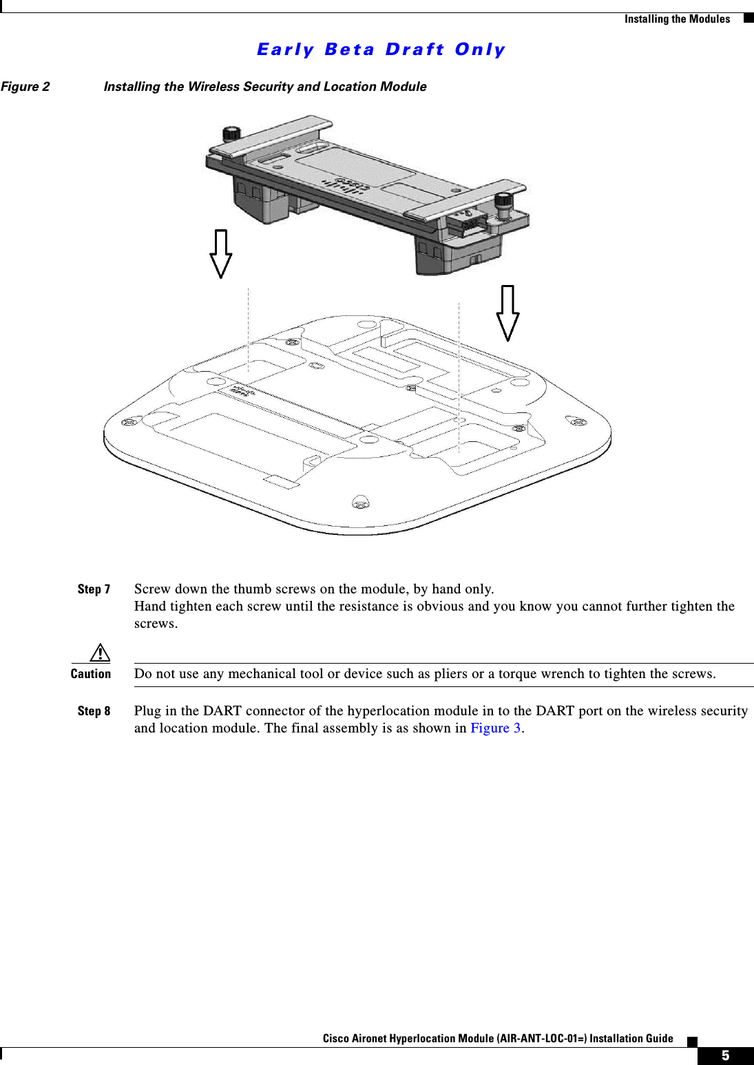
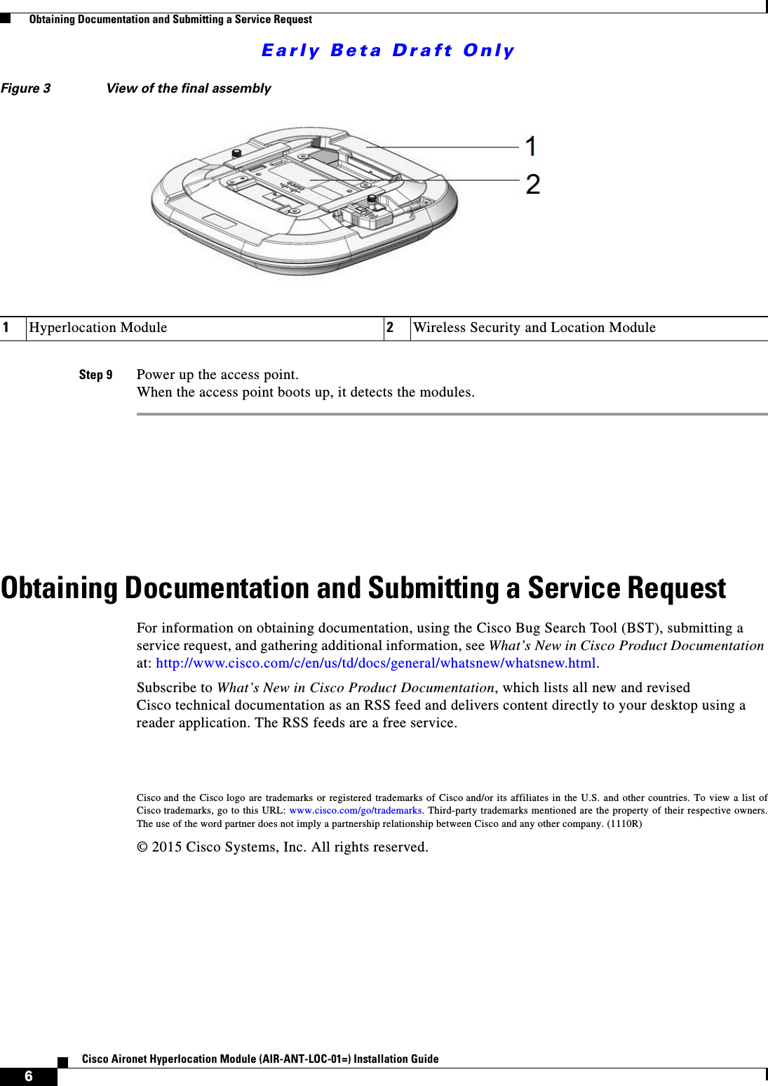
Installation Guide
Navigation menu
Upload a User Manual
Namespaces
Wiki Guide
HTML
PDF
Info
Views
User Manual
Discussion / Help
Navigation