Cisco Systems 102094 Aironet 802.11ac User Manual ant2566d4m Copy
Cisco Systems Inc Aironet 802.11ac ant2566d4m Copy
Contents
- 1. Installation Guide
- 2. Users Manual
Installation Guide

Cisco Systems, Inc.
www.cisco.com
Early Beta Draft Only
Cisco Aironet Hyperlocation Module
(AIR-ANT-LOC-01=) Installation Guide
First Published: March 11, 2015
This document outlines the specifications for the Cisco Aironet Hyperlocation Module
(AIR-ANT-LOC-01=) and provides instructions for mounting it.
The following information is provided in this document.
• System Overview, page 2
• System Requirements, page 3
• Safety Precautions, page 4
• Installation Notes, page 5
• Installing the Modules, page 3
• Obtaining Documentation and Submitting a Service Request, page 6

Early Beta Draft Only
2
Cisco Aironet Hyperlocation Module (AIR-ANT-LOC-01=) Installation Guide
System Overview
System Overview
The Hyperlocation module is a 32 element antenna design that provides 360 degree coverage around
supported access points — currently the 3600 and 3700 series APs. It is designed to integrate into the
Cisco Aironet Wireless Security and Location Module (RM3010L) providing precise RF Angle of
Arrival (AoA) information allowing the operating system a much more granular approach to the location
of a client device.
The hyperlocation module along with RM3010L helps in providing a location accuracy of less than a
meter for a wireless clients, using WiFi and Bluetooth technology.
The module operates in both the 2.4-GHz and 5-GHz frequency ranges and is designed for indoor use.
Together with the Hyperlocation module, the Wireless Security and Location Module is fully capable of
providing the following monitoring and security services:
• RRM
• CleanAir
• wIDS/wIPS
• Rogue Detection
• Context Aware – Location
• 802.11ac capability @ 20, 40 and 80 MHz operation
• Integrated Bluetooth Low Energy “BLE” Beacon capability
• External DART connector for location capability with the use of the Hyper-Location module
(antenna array)
Early Beta Draft Only
3
Cisco Aironet Hyperlocation Module (AIR-ANT-LOC-01=) Installation Guide
System Requirements
System Requirements
This hyperlocation module is designed for indoor use with Cisco Aironet 3600 and 3700 access point
along with the Cisco Aironet Wireless Security and Location module (AIR-RM3010L-UXK9=).
Installing the Modules
Tools and Equipment Required
No specialized tools are required for installing the modules.
Mounting the modules
Step 1 Remove the modules from the packaging.
Step 2 Power down the access point.
Note If you install a module while the AP is powered on, the AP will reboot.
Step 3 Unmount the access point, in the reverse order of installing it.
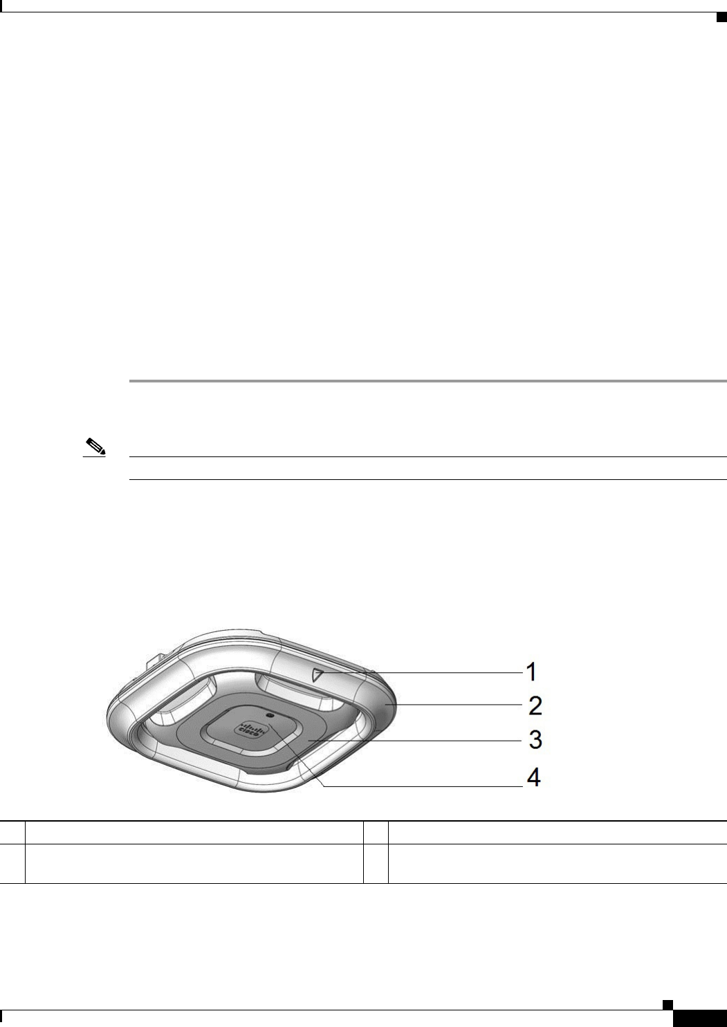
Step 4 Position the hyperlocation module around the AP as shown in Figure 1. Note that the arrow on the
module and the face of the AP with the logo and LED should be aligned as shown in Figure 1.
Figure 1 Positioning the hyperlocation module around the AP
1Arrow on hyperlocation module 3Face of the AP
2Hyperlocation module 4The position of the LED and the logo on the face of the
AP.
Early Beta Draft Only
4
Cisco Aironet Hyperlocation Module (AIR-ANT-LOC-01=) Installation Guide
Installing the Modules
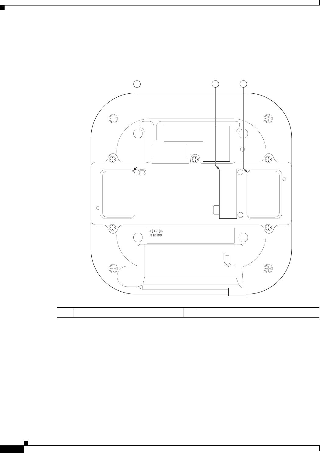
Step 5 Peel off the Module Port Protective Cover from the back of the access point to reveal the module port
connector, labeled 2 in the following figure.
The PCIe connector on the wireless security and location module will go into the AP’s module port
connector.
1Openings for module’s antennas 2Removable Module Port Protective Cover
345379
12 1
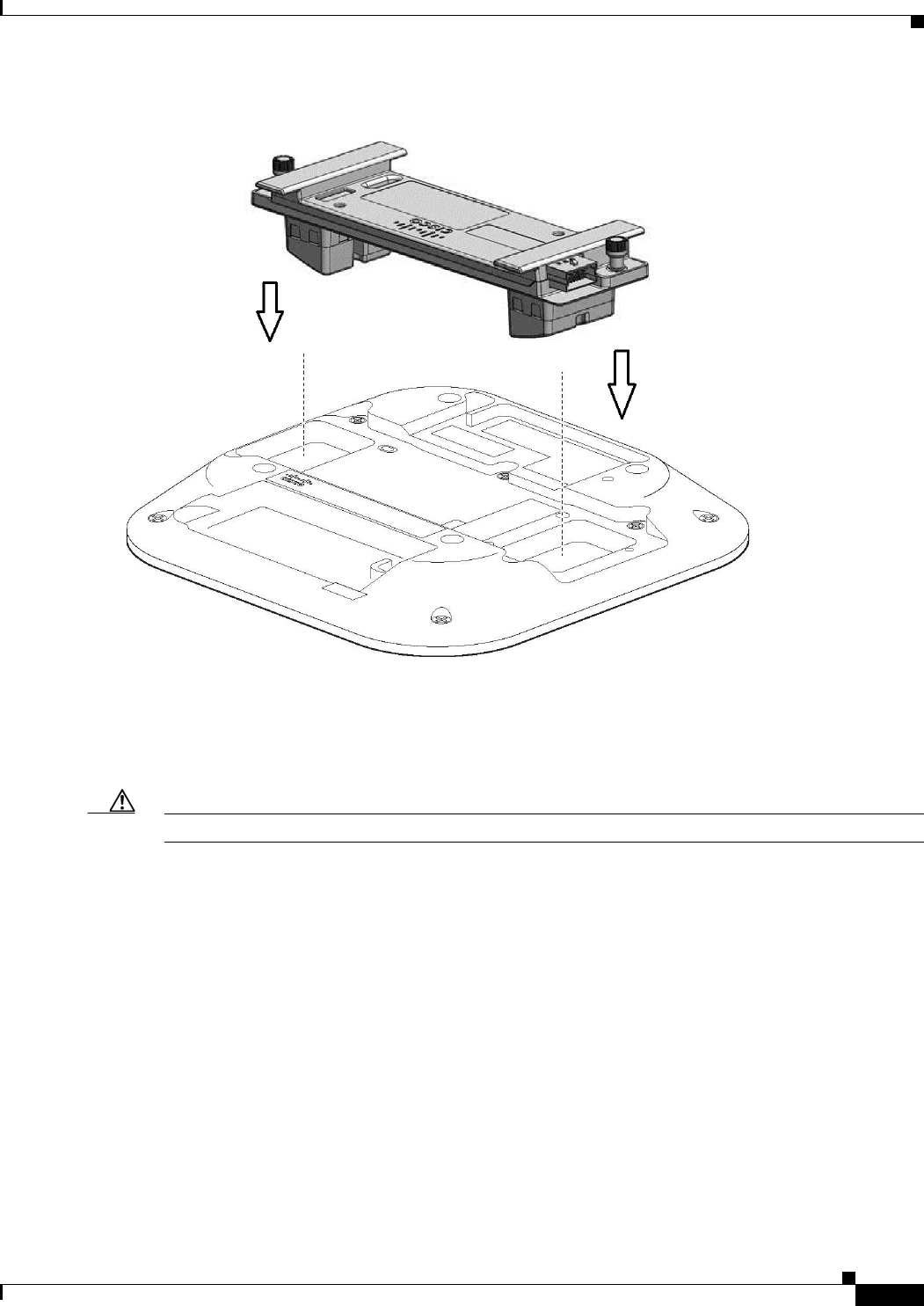
Step 6 Align the PCIe connector with the module port connector on the back of the access point and click the
module down into place. Press firmly on the center of the module to properly seat the PCIe connector
into the AP’s module port connector.
Early Beta Draft Only
5
Cisco Aironet Hyperlocation Module (AIR-ANT-LOC-01=) Installation Guide
Installing the Modules
Figure 2 Installing the Wireless Security and Location Module
Step 7 Screw down the thumb screws on the module, by hand only.
Hand tighten each screw until the resistance is obvious and you know you cannot further tighten the
screws.
Caution Do not use any mechanical tool or device such as pliers or a torque wrench to tighten the screws.
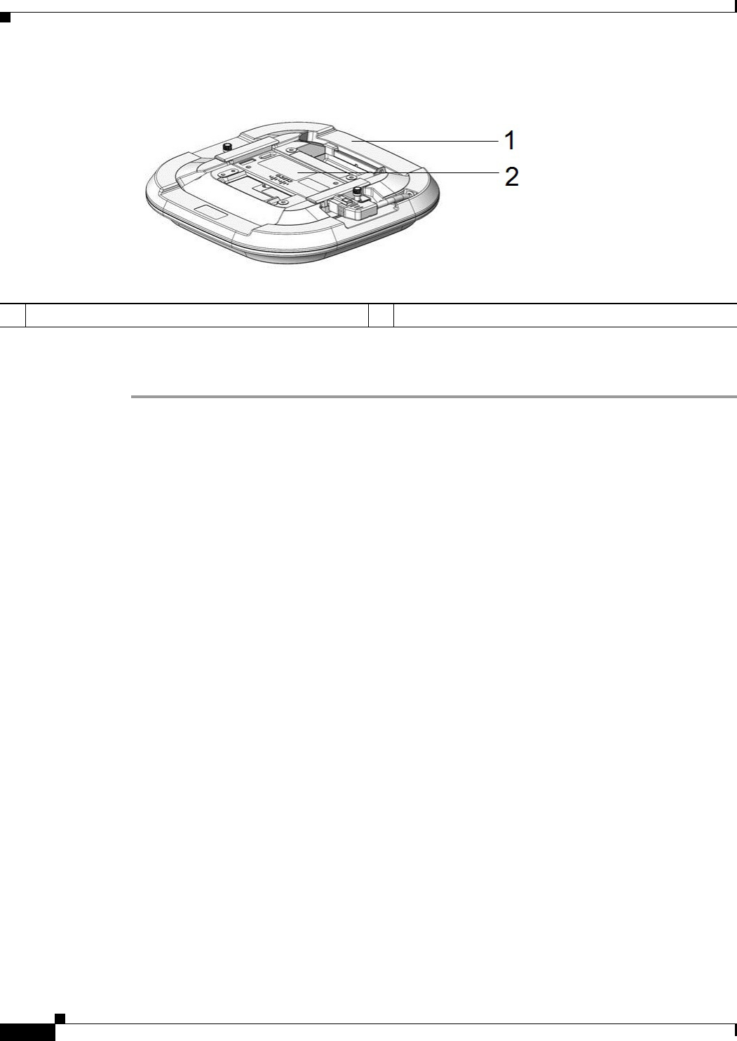
Step 8 Plug in the DART connector of the hyperlocation module in to the DART port on the wireless security
and location module. The final assembly is as shown in Figure 3.
Early Beta Draft Only
6
Cisco Aironet Hyperlocation Module (AIR-ANT-LOC-01=) Installation Guide
Obtaining Documentation and Submitting a Service Request
Figure 3 View of the final assembly
Step 9 Power up the access point.
When the access point boots up, it detects the modules.
Obtaining Documentation and Submitting a Service Request
For information on obtaining documentation, using the Cisco Bug Search Tool (BST), submitting a
service request, and gathering additional information, see What’s New in Cisco Product Documentation
at: http://www.cisco.com/c/en/us/td/docs/general/whatsnew/whatsnew.html.
Subscribe to What’s New in Cisco Product Documentation, which lists all new and revised
Cisco technical documentation as an RSS feed and delivers content directly to your desktop using a
reader application. The RSS feeds are a free service.
Cisco and the Cisco logo are trademarks or registered trademarks of Cisco and/or its affiliates in the U.S. and other countries. To view a list of
Cisco trademarks, go to this URL: www.cisco.com/go/trademarks. Third-party trademarks mentioned are the property of their respective owners.
The use of the word partner does not imply a partnership relationship between Cisco and any other company. (1110R)
© 2015 Cisco Systems, Inc. All rights reserved.
1Hyperlocation Module 2Wireless Security and Location Module