Cisco Systems 102103 Cisco Aironet 802.11ac Dual Band Outdoor Access Point User Manual 1560hig
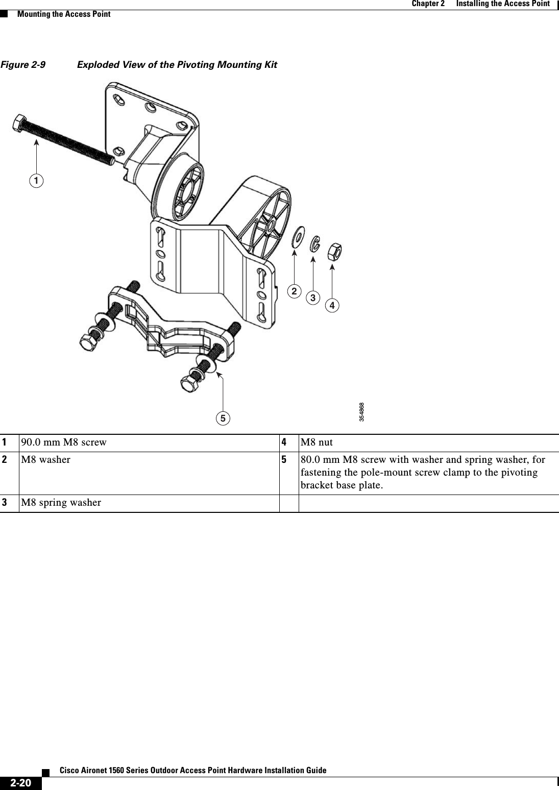
Cisco Systems Inc Cisco Aironet 802.11ac Dual Band Outdoor Access Point 1560hig
UserManual.wiki
>
Cisco Systems
>
102103 User Manual
>
1560hig_1 of 2
Contents
1.
1560hig_1 of 2
2.
1560hig_2 of 2
1560hig_1 of 2
Navigation menu
Upload a User Manual
Namespaces
Wiki Guide
HTML
PDF
Info
Views
User Manual
Discussion / Help
Navigation
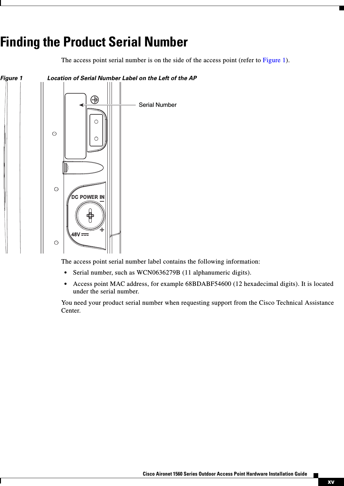
![viiiCisco Aironet 1560 Series Outdoor Access Point Hardware Installation Guide ConventionsThis publication uses the following conventions:Notes use the following conventions:Note Means reader take note. Notes contain helpful suggestions or references to materials not contained in this manual.Cautions use the following conventions:Caution Means reader be careful. In this situation, you might do something that could result in equipment damage or loss of data.Chapter 3 Troubleshooting Provides basic troubleshooting procedures for the access point. Appendix A Safety Guidelines and WarningsProvides the safety warnings and guidelines that need to be strictly followed during the deployment of the access point.Appendix B Declarations of Conformity and Regulatory InformationDescribes the regulatory conventions to which the access point conforms and provides guidelines for operating access points in Japan.Appendix E Access Point Pinouts Describes the connector pinouts for the access point.Chapter Title DescriptionConvention Descriptionboldface font Commands, command options, and keywords are in boldface.italic font Arguments for which you supply values are in italics.[ ] Elements in square brackets are optional.screen font Terminal sessions and information the system displays are in screen font.boldface screen font Information you must enter is in boldface screen font.italic screen font Arguments for which you supply values are in italic screen font.^ The symbol ^ represents the key labeled Control. For example, the key combination ^D in a screen display means hold down the Control key while you press the D key.< > Nonprinting characters, such as passwords, are in angle brackets.](https://usermanual.wiki/Cisco-Systems/102103.1560hig-1-of-2/User-Guide-3213618-Page-8.png)
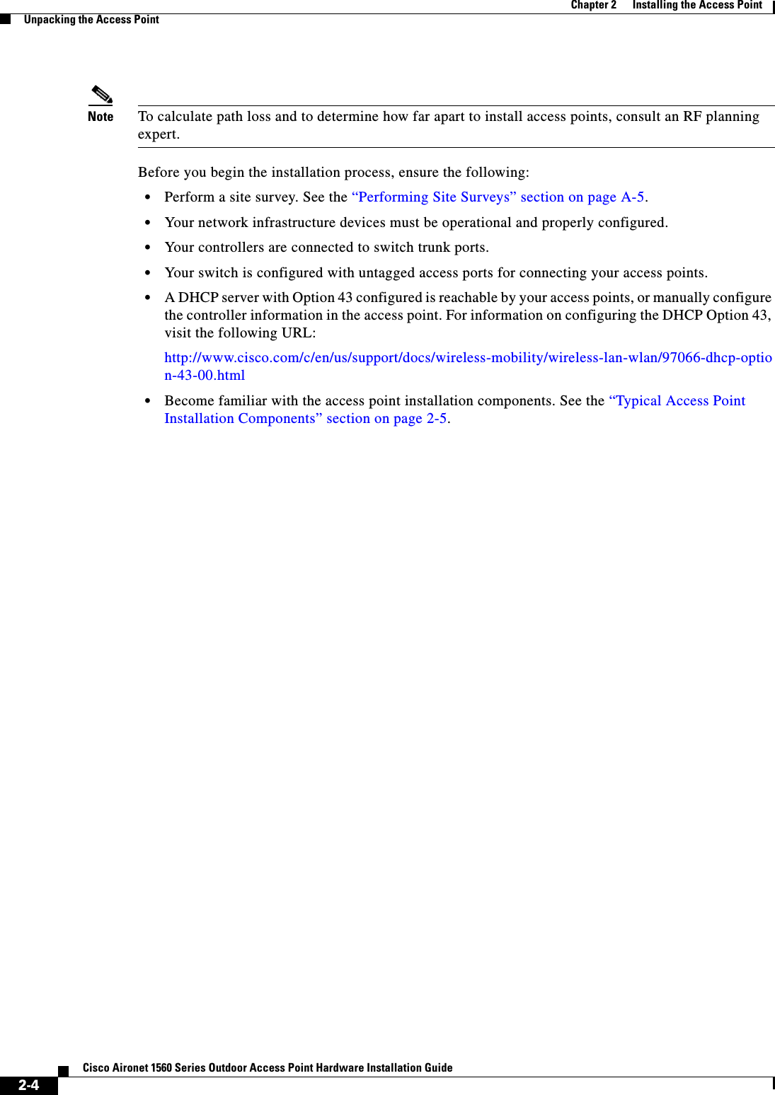
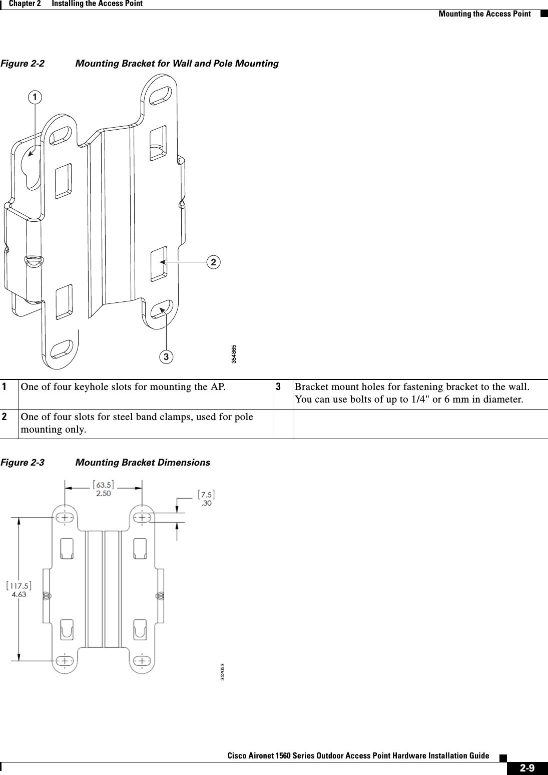
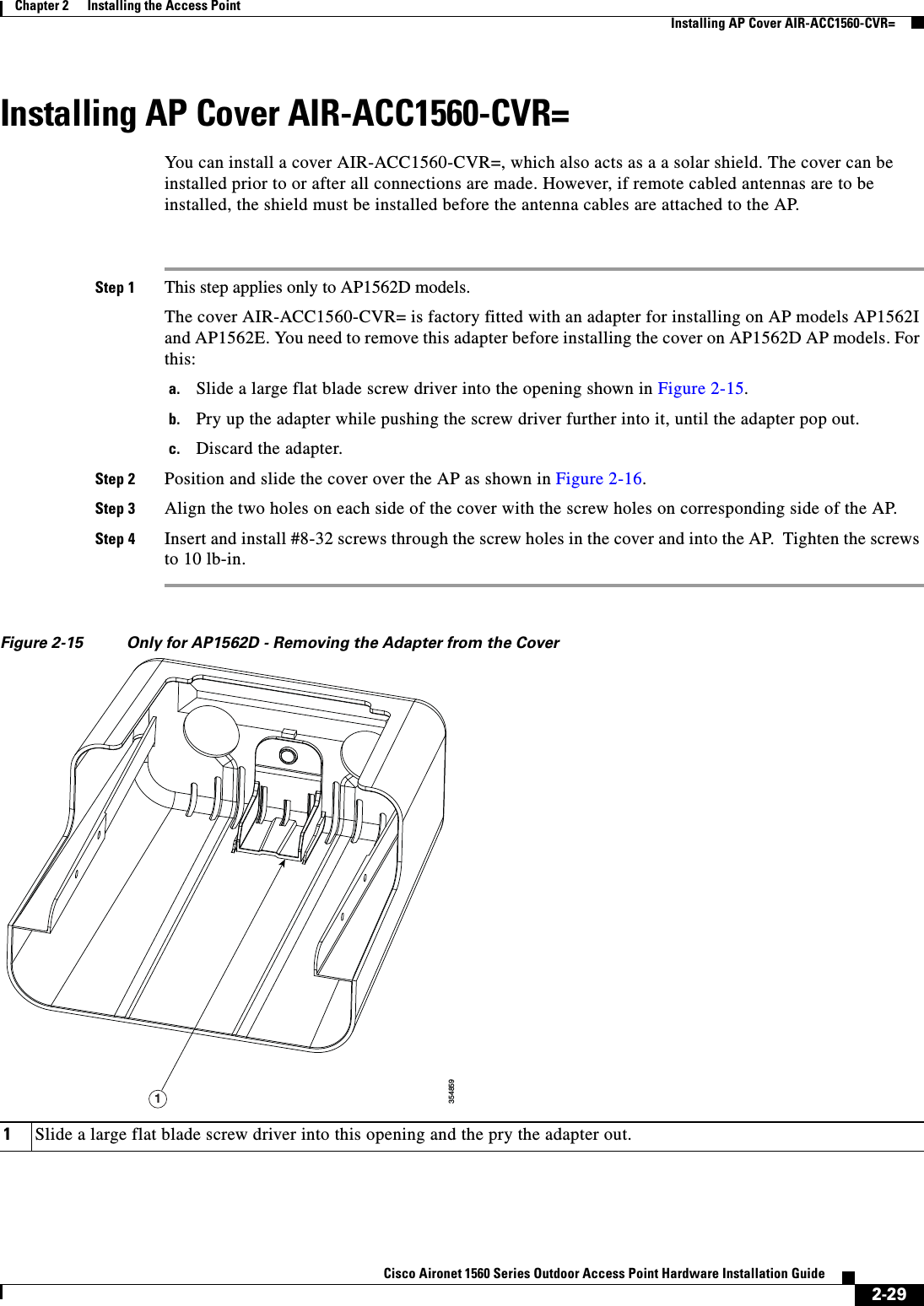
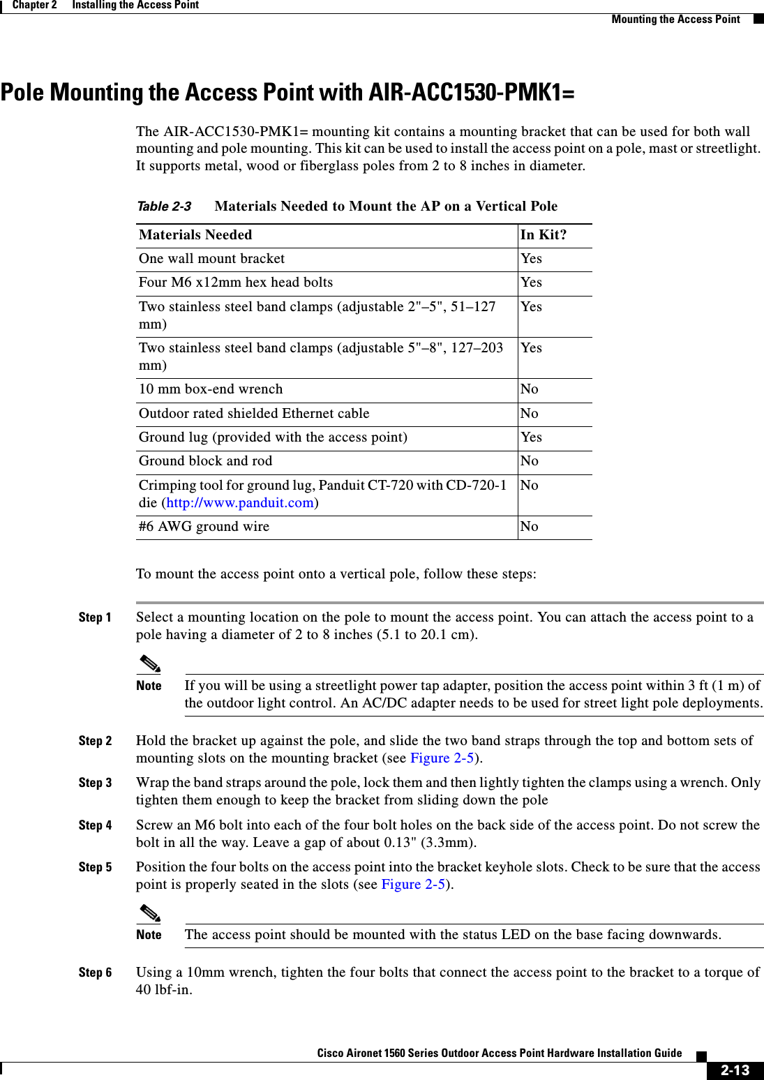
![2-12Cisco Aironet 1560 Series Outdoor Access Point Hardware Installation Guide Chapter 2 Installing the Access PointMounting the Access PointFigure 2-4 Mounting Bracket for Wall and Pole Mounting AP with Power Supply 1One of four keyhole slots for mounting the AP. 3Screw holes for fastening the power supply to the bracket.2Three of six bracket mount holes for fastening the bracket to a wall. Support bolts of up to 1/4" (6 mm) in diameter.3548477.10 3132[180.3][117.5]4.63[7.5].30[63.5]2.50](https://usermanual.wiki/Cisco-Systems/102103.1560hig-1-of-2/User-Guide-3213618-Page-44.png)
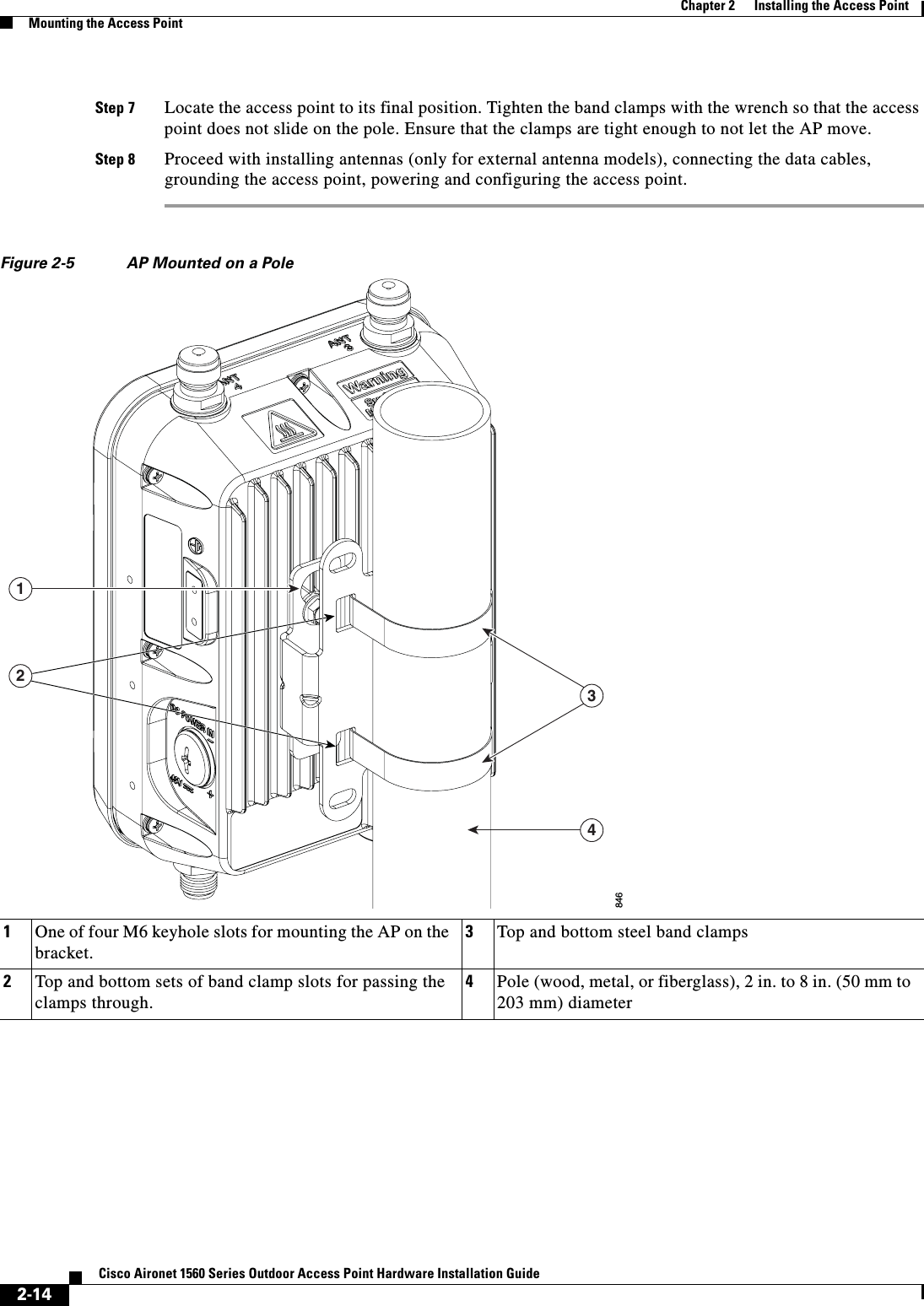
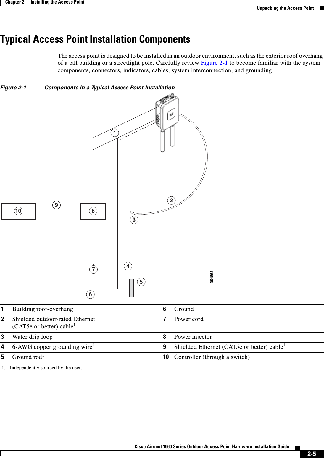
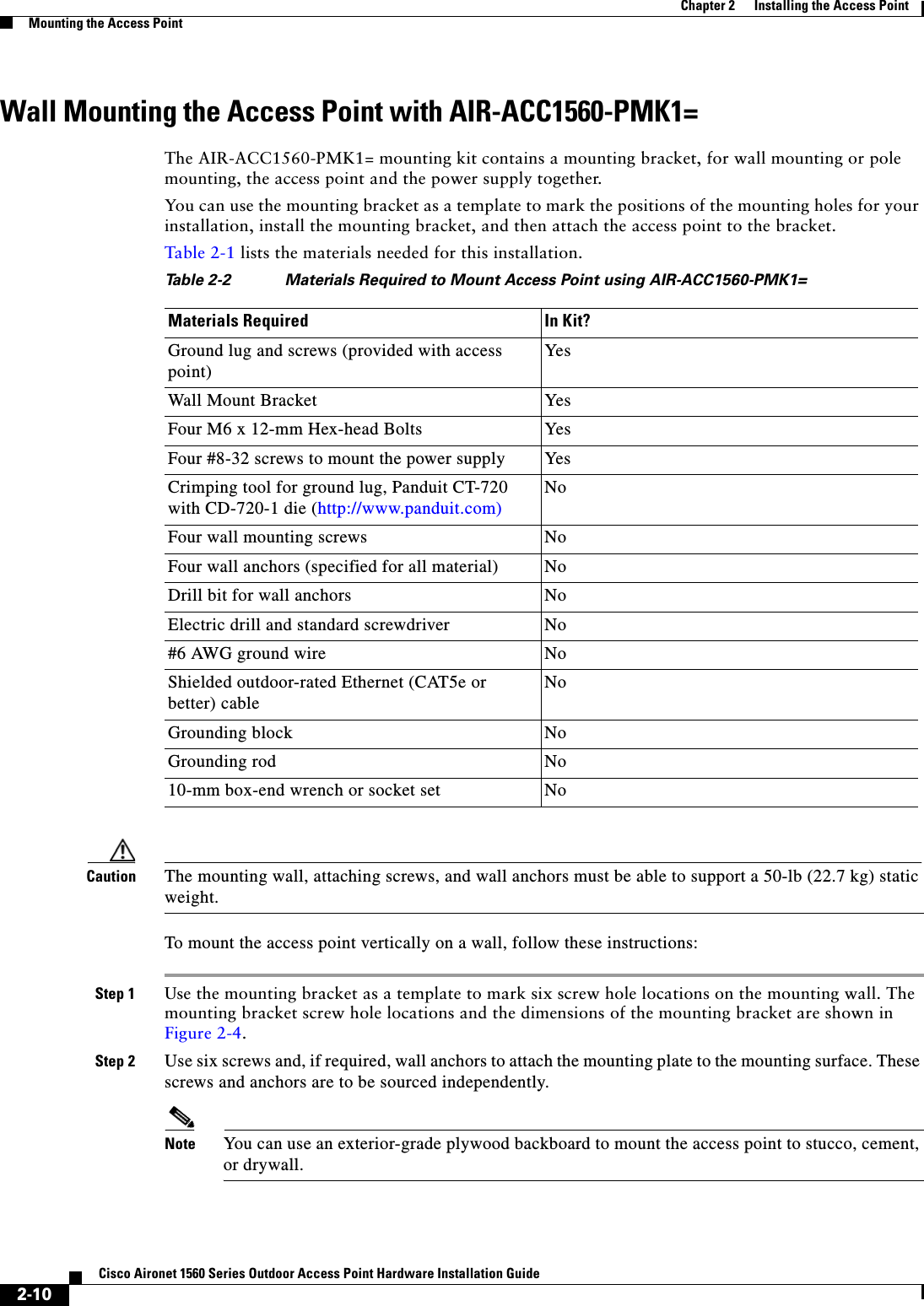
![2-19Cisco Aironet 1560 Series Outdoor Access Point Hardware Installation Guide Chapter 2 Installing the Access PointMounting the Access PointFigure 2-7 Pivoting Mounting Bracket Figure 2-8 Pivoting Mounting Bracket Dimensions 1One of four bolt holes for fastening to the back of the AP. This is the AP-plate end of the bracket, and is fastened to the back of the AP.3Screw holes for wall mounting.These screw holes can also be used as slots for steel band clamps in pole-mount installations.2Wall-plate end of the bracket. This plate is fastened to the wall.3548662133520001003.94281.10562.20 2x M8 THRU 4X 6.5MM THRU 17.10.67SLOT LENGTH [4.0].16SLOT WIDTH](https://usermanual.wiki/Cisco-Systems/102103.1560hig-1-of-2/User-Guide-3213618-Page-51.png)