Cisco Systems 102103 Cisco Aironet 802.11ac Dual Band Outdoor Access Point User Manual 1560hig
Cisco Systems Inc Cisco Aironet 802.11ac Dual Band Outdoor Access Point 1560hig
UserManual.wiki
>
Cisco Systems
>
102103 User Manual
>
1560hig_2 of 2
Contents
1.
1560hig_1 of 2
2.
1560hig_2 of 2
1560hig_2 of 2
Navigation menu
Upload a User Manual
Namespaces
Wiki Guide
HTML
PDF
Info
Views
User Manual
Discussion / Help
Navigation
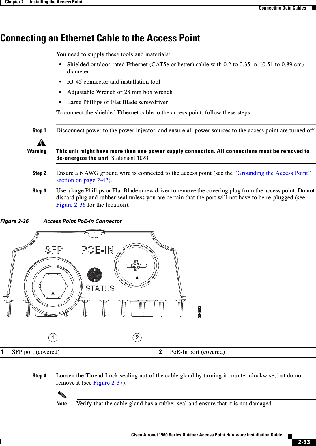
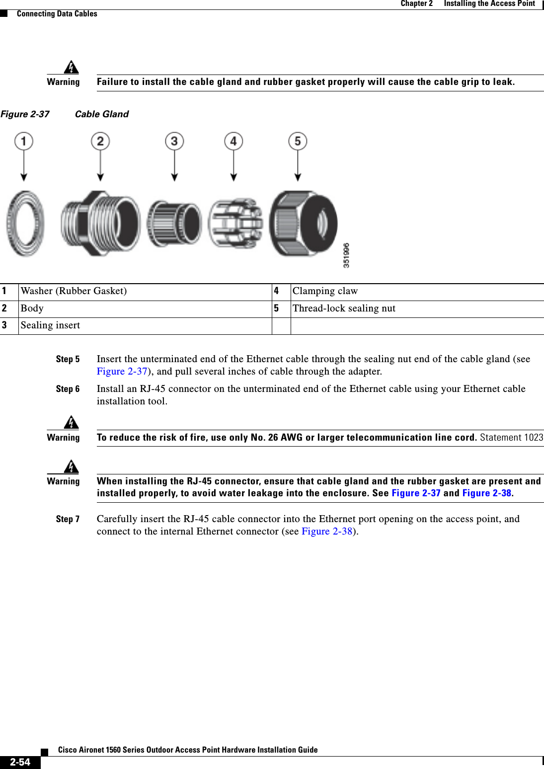
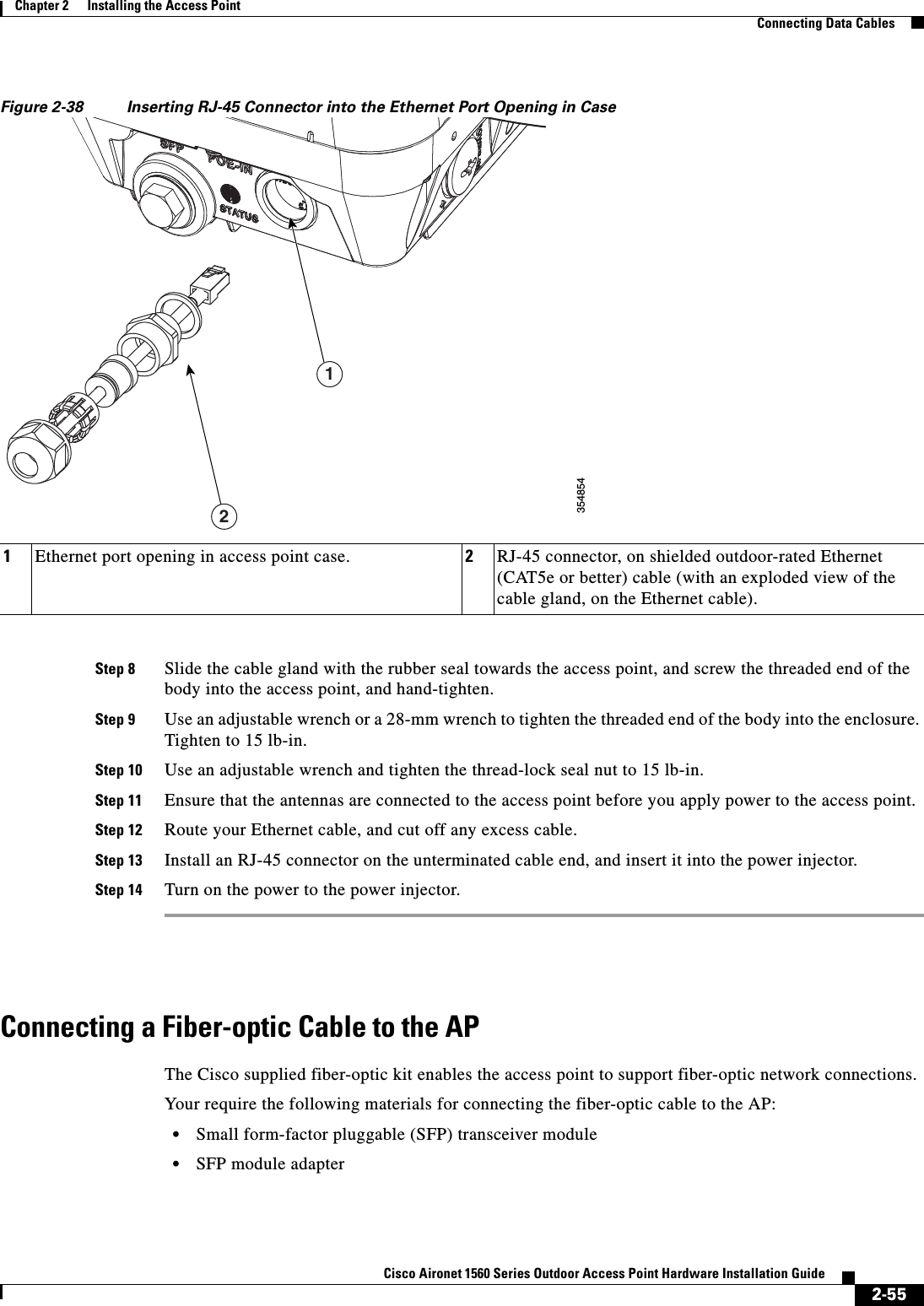

![A-4Cisco Aironet 1560 Series Outdoor Access Point Hardware Installation Guide Appendix A Safety Guidelines and Warnings•Use directional antennas, and keep them away from each other.•Cable the radios together using a combination of attenuators, combiners, or splitters to achieve a total attenuation of at least 60 dB.For a radiated test bed, the following equation describes the relationships among transmit power, antenna gain, attenuation, and receiver sensitivity:txpwr + tx gain + rx gain - [attenuation due to antenna spacing] < max rx input levelWhere:txpwr = Radio transmit power leveltx gain = transmitter antenna gainrx gain = receiver antenna gainFor a conducted test bed, the following equation describes the relationships among transmit power, antenna gain, and receiver sensitivity:txpwr - [attenuation due to coaxial components] < max rx input levelCaution Under no circumstances should you connect the antenna port from one access point to the antenna port of another access point without using an RF attenuator. If you connect antenna ports, you must not exceed the maximum survivable receive level of 0 dBm. Never exceed 0 dBm, or damage to the access point can occur. Using attenuators, combiners, and splitters having a total of at least 60 dB of attenuation ensures that the receiver is not damaged and that PER performance is not degraded.Safety Precautions when Installing AntennasWarningDo not locate the antenna near overhead power lines or other electric light or power circuits, or where it can come into contact with such circuits. When installing the antenna, take extreme care not to come into contact with such circuits, as they may cause serious injury or death. For proper installation and grounding of the antenna, please refer to national and local codes (e.g. U.S.: NFPA 70, National Electrical Code, Article 810, Canada: Canadian Electrical Code, Section 54). Statement 2801. Before you install an antenna, contact your Cisco account representative to explain which mounting method to use for the size and type of antenna that you are about to install.2. Select your installation site with safety, as well as performance, in mind. Remember that electric power lines and phone lines look alike. For your safety, assume that any overhead line can kill you.3. Contact your electric power company. Tell them your plans and ask them to come look at your proposed installation.4. Plan your installation carefully and completely before you begin. Each person involved in an installation should be assigned to a specific task and should know what to do and when to do it. One person should be in charge of the operation to issue instructions and watch for signs of trouble.5. When installing your antenna, follow these guidelines:–Do not use a metal ladder.–Do not work on a wet or windy day.–Do dress properly—wear shoes with rubber soles and heels, rubber gloves, and a long-sleeved shirt or jacket.](https://usermanual.wiki/Cisco-Systems/102103.1560hig-2-of-2/User-Guide-3213627-Page-36.png)