Cisco Systems 2305-BTS2-R1 Base Station Transmitter User Manual Ripwave Base Station I C Guide
Cisco Systems, Inc Base Station Transmitter Ripwave Base Station I C Guide
Contents
Manual part 4
Navini Networks, Inc. Ripwave Base Station I&C Guide
35
Base Station Components
Base Transceiver Station (BTS)
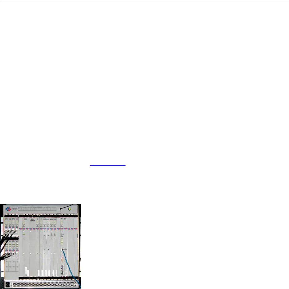
The BTS consists of the RF Power Amplifiers (PAs), the digital circuit cards, the backplane, and
the mechanical enclosure or housing. It performs the signal processing and RF transmission for
the system. There are three types of chassis: Combo, Split, and Tower Top Amplifier (TTA). The
Combo Chassis is used primarily with 2.4 GHz systems. The Split Chasses is used for all other
(2.3, 2.5, 2.6 GHz) systems (Figure 5). The TTA is the latest chassis design, and is available at
this time for 2.4 and 3.5 GHz systems.
The chassis is compartmentalized into two sections - the RF shelf and the Digital shelf. The BTS
connects to the network using a 10/100 Base-T Ethernet connection or up to 8 T1 interfaces. Up
to three BTS assemblies can be installed per system, depending on the configuration. The BTS
specifications are provided in Appendix C.
Figure 5: BTS Chassis
TTA ChassisTTA ChassisTTA ChassisTTA Chassis

Navini Networks, Inc. Ripwave Base Station I&C Guide
36
Radio Frequency Subsystem (RFS)
The Radio Frequency Subsystem (RFS) is mounted on a transmission tower or building rooftop.
It transmits and receives data to and from the Ripwave Modem using a digital beam forming
transmission technique. The RFS may be either a panel antenna or an omni antenna (Figure 6).
The RFS data sheets are provided in Appendix E.
An RFS panel transmits in a directional mode, covering a transmit angle of 120 degrees. The
antenna can be used as a single mode antenna, or it can be used in a group of two or three
sectored antennas, covering 240 and 360 degrees respectively. Each panel requires a BTS to
operate. For example, in a tri-sectored cell with 3 panels, you would need 3 BTSs. The omni
antenna provides omni-directional coverage of 360 degrees.
An RFS panel or omni contains eight (8) antenna elements, cavity filters, and, optionally, low
noise amplifiers (LNA). In the TTA configurations, the PAs also are located in the RFS
(antenna) by the LNAs and cavity filters.
Navini Networks, Inc. Ripwave Base Station I&C Guide
37
Global Positioning System (GPS)
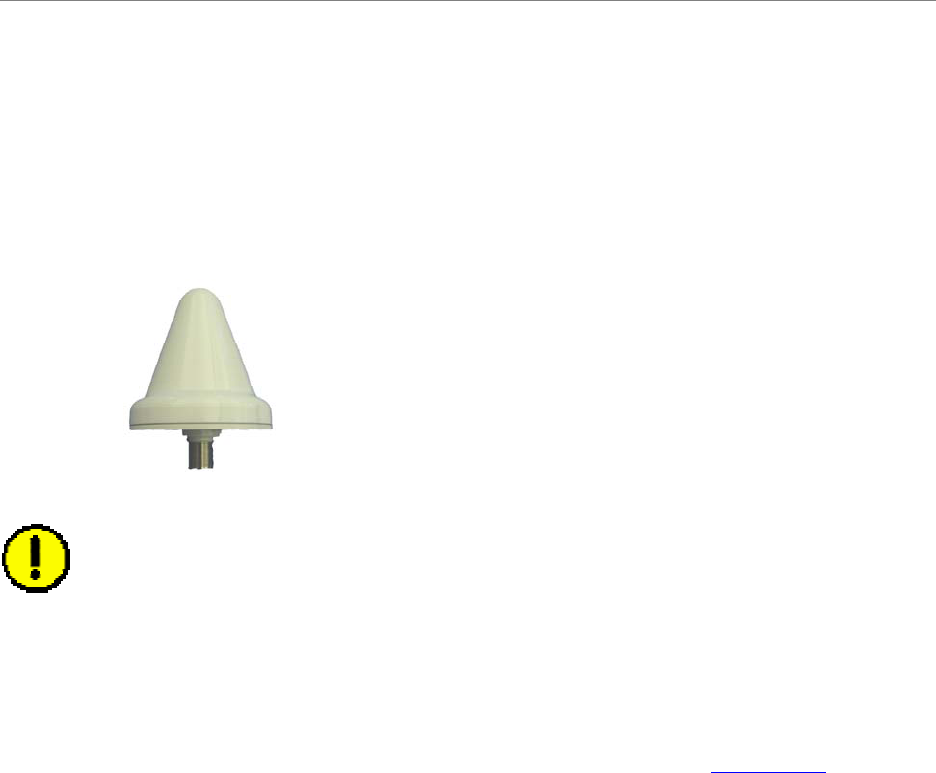
One Global Positioning System (GPS) antenna is used with each Base Station to provide a
timing signal for synchronizaton. A second GPS antenna can be provided for redundancy. The
Ripwave Base Station uses the VIC 100 GPS Antenna (Figure 7).
Figure7: VIC 100 GPS Antenna
CAUTION! GPS synchronization is essential for the BTSs in a network not to interfere
with one another
Mounting Racks & Enclosures
The BTS can be installed indoors or outdoors in industry standard 19- or 23-inch racks. Rack
adapters are needed to mount the equipment in a standard 23-inch rack. For outdoor BTSs, the
customer can supply any standard enclosure from a multitude of vendors. Appendix E offers
suggestions for outdoor BTS enclosures. Figure 8 shows 3 BTSs installed indoors.
Accessibility
Ripwave BTS equipment is required to be installed in a restricted access location, in accordance
with NEC/CEC standards. Only authorized personnel should have access to this equipment.

Navini Networks, Inc. Ripwave Base Station I&C Guide
38
Technical Specifications
Table 2: Technical Specifications
COMBO
(no longer
in production) SPLIT TTA
Frequency Band (GHz) 2.4 2.6 2.3
2.5
2.6 2.4 2.6 3.5
Frequency Band (Name) ISM MMDS WCS/
ITFS/
MMDS ISM MMDS BWA/FWA–
Frequency Range (GHz) 2.400–2.473 2.602–2.638 2.305–2.385
2.500–2.596
2.596–2.686 2.400–2.483 2.596–2.686 3.410–3.600
Watt 725 1150 1150 435 390 380
Maximum
Power Dissipation
(Thermal Load) BTU per
hour 2475 3925 3925 1485 1331 1297
Rectifier Rating (Watt)* 975 1500 1500 504 724 614
Circuit Breaker Rating (Amp) 60 RF Shelf: 50
Dig. Shelf: 20 40
Duty Cycle 75%
Input Voltage +21 to 27 VDC
Relative Humidity of
BTS Operating Environment 0% to 95% relative humidity, non-condensing
Operating Temperature (°Celsius) 0 to 50
Storage Temperature (°Celsius) –40 to +70
Air Flow (on each shelf) Fresh air intake along the lower front vertical panel,
air exhaust out of the upper rear of the chassis
Downlink DQPSK, 8PSK & QAM16
Modulation Uplink DQPSK
Multiple Access Scheme Multi-Carrier Synchronous Beam-forming (MCBS) CDMA
Power Control Forward & reverse, open & closed loop
*The BTS must be connected to a power supply/rectifier that is UL listed
(continued on the next page)
Navini Networks, Inc. Ripwave Base Station I&C Guide
39
COMBO
(no longer
in production) SPLIT TTA
Frequency Band (GHz) 2.4 2.6 2.3
2.5
2.6 2.4 2.6 3.5
Omni 2° electrical downtilt –
Antenna Downtilt 120° panel 6° electrical downtilt (fixed) plus
0°to 10° mechanical uptilt (adjustable) 6° electrical downtilt (fixed) plus
–4° to +8° mechanical uptilt (adjustable)
Omni 8 dBi
Antenna Gain per
antenna element
(Approximate) 120° panel 15 dBi
Backhaul Interfaces 10/100 BaseT Ethernet or ATM over T1/E1;
up to 8 T1s/E1s with or without IMA, long haul support
Bandwidth Allocation Dynamic
Duplex Format Time Division Duplex
RF:
14x19x15.2
Chassis Mechanical Dimensions
(inches H x W x D) 30 x 19 x 14 Digital:
19.2x19x12.9
19.2 x 19 x 12.9
RF: 82
Chassis Weight (lb) 60 Digital: 33 36
Omni Antenna Mechanical
Dimensions
(inches H x Diameter) 60 x 15 56.6 x 13.2
Omni Antenna Weight (lb) 65 52
Panel Antenna Mechanical
Dimensions
(inches H x W x D) 48 x 23 x 10 54 x 23
x 7.5 38 x 19
x 20
Panel Antenna Weight (lb) 64 81* 50
Polarization Vertical
Downlink 18
Beam Forming
Gain (dB) Uplink 9
* including the bracket mount

Navini Networks, Inc. Ripwave Base Station I&C Guide
40
BTS Input/Output Specifications
Table 3: BTS Input/Output Specifications
Item Description Termination Protection specified in
Manual
+24 VDC Power +21 to +27 VDC input,
–/+ terminals Power Supply/Rectifier
customer equipment
Rectifier must be UL-
listed, comply with
UL60950 or UL60950-1
and have earthed SELV
output
GND Chassis Ground Connection Earth Ground GND required
T1/E1 T1/E1 communication lines off
CC card
T1s/E1s interface switch
customer equipment.
Typical installation
requires DSU or CSU
providing loopback
capability and primary
Type 1 protection.
In-Line Devices such as
DSU/CSU/TSU/PPC must
be UL497 listed
Ethernet 10/100 BaseT communication off
CC card PC/Router/Hub/Gateway Not Required
UART D sub serial connection off CC
card, used for on-site
communication to PC PC Not Required
BBU
BBU connector can accept up to
4 alarm inputs plus GND. BTS
monitors alarms and reports
back condition to EMS. Inputs
come from dry contacts at the
BBU side, normally open circuit,
can be closed circuit for alarmed
condition
BBU customer equipment Not Required
Cabinet Alarms
Door open and HMC alarms plus
2 GND inputs. BTS monitors
alarms and reports back
condition to EMS. Inputs come
from dry contacts at the BBU
side, normally open circuit, can
be closed circuit for alarmed
condition
Cabinet customer
equipment Not Required
(continued on the next page)

Navini Networks, Inc. Ripwave Base Station I&C Guide
41
Item Description Termination Protection specified in
Manual
TDD SYNC
TDD Sync is a TTL Sync pulse at
10 ms cycle rate, 0 t0 +5V swing,
which is 5 µs long in width. This
output of BTS is used for
equipment debugging and to
synchronize test equipment
Test equipment such as
oscilloscope or spectrum
analyzer Not Required
GPS Antenna
A/B (2)
The GPS coax cable connected
to GPS antenna LNA carries +5
VDC and a 1.57 GHz RF signal.
RF is an input to BTS; DC is an
output from BTS
GPS antenna/LNA, which
is normally located at BTS
or on hut of BTS; not on
tower
Not Required
RFS Calibration
Cable (1)
This coax cable is an RF signal
path to the RFS. The signal is a
low power, at the operating
frequency of the BTS
RFS connection to BTS Lightning protection
devices must be UL497
listed
RFS Antenna
Cables (8)
This coax cables are an RF
signal path to the RFS. The
signal frequency is the operating
frequency of the BTS. In the
TTA version of the BTS, these
cables also contain a +24 VDC
component and the 10.7 MHz
TDD signal on the center
conductor.
RFS connection to BTS Lightning protection
devices must be UL497
listed
Power/Data
Cable
This cable is a 6-twisted pair
bundle cable used for sending
low-current DC voltage to the
RFS at +8 to +12 V as well as
RS485 digital bus for TDD
control
RFS connection to BTS Lightning protection
devices must be UL497
listed

Navini Networks, Inc. Ripwave Base Station I&C Guide
42
Chapter 2: Installation
Pre-installation
As was shown in Figure 4, prior to installing the equipment a number of planning and acquisition
activities take place. The installation itself takes only about 2 days. The I&C crew may or may
not be involved with all the pre-installation activities. Of these, they are most likely to be
involved in the Site Candidate Evaluation, the gathering of data for the Interference Analysis,
and the Antenna Power & Cable Selection step of the process.
Project Plan
A Project Plan is a document that lays out the work to be done, the objectives of the project, the
schedule, resources required, and so forth. If Navini is performing the I&C activities, a Project
Manager is assigned. The Project Manager prepares the Project Plan and shares it with the
Navini and customer teams.
Coverage Prediction Map
Early in the planning of deployment of Ripwave Base Station equipment, an RF Engineer will go
through the process of studying the RF environment of the candidate sites that the customer has
identified. Readings are taken and analyzed at each site in order to predict what range of
coverage can be expected from installing a Base Station at the site.
Coverage predictions account for both Base Station performance and Marketing objectives with
the service. The customer accomplishes the latter as part of the decisions concerning site
selection.
Site Candidate Evaluation
Often Technicians will be very comfortable with either the networking side or the wireless side
of the system, but not usually both. To evaluate a potential install site, a form helps ensure all
aspects of the site have been considered. Information about the site is recorded on the form.
Since each site is unique, the form helps to ensure nothing is taken for granted or assumed about
the installation site for the Ripwave equipment.

Navini Networks, Inc. Ripwave Base Station I&C Guide
43
A copy of this form may be found in Appendix A. It includes places to capture the logistics of
the site, tower or rooftop mount possibilities, GPS coordinates, type of antenna to be installed,
whether or not an outdoor enclosure is provided, power availability, distance between connection
points, ventilation, a place for drawings from every angle, etc. It is from this information that the
site will be designed, then installed to plan.
Interference Analysis
As part of deploying a Ripwave Base Station, the Field Service Engineer must collect critical
information from the site. The data is provided to the RF Engineering personnel, who can then
evaluate the Radio Frequency (RF) conditions. The RF Engineer analyzes the data for existing
interference from other sources, and takes that into account when creating the coverage
prediction map.
The RF Engineer, in turn, supplies to the Field Service Engineer at the site valuable data
parameters and configuration information unique to each system and each site. In addition to
coverage, though, the interference analysis also helps to predict the quality of service, the power
requirements to get above the noise floor, and other expectations regarding the site.
This study helps Navini and the customer decide which type of system (frequency) and antenna
(panel or omni) will provide the best results. To collect the data the on-site Technician or Field
Engineer performs an Interference Sweep Procedure (Appendix B) and supplies that data to the
RF Engineer(s).
Site Selected & Designed
After evaluating the potential sites and the coverage prediction, the customer must select the
specific site where the Base Station is to be deployed. The site must be carefully blueprinted to
prepare for equipment ordering and installation. Navini can supply specifications and drawings
to help the customer design the site. Refer to Appendices C D, E, F, and G for BTS
Specifications, RFS Data Sheets, BTS Outdoor Enclosures Manufacturers, Rectifier/Battery
Backup Manufacturers, and a sample Base Station drawing. Check all regulatory standards (refer
to Chapter 1, Page 8 “Regulatory Information”) prior to installation.
Network Architecture Plan
The IP Networking community involved in the project, both from Navini and the customer, often
work together to analyze and plan how the Ripwave system will be integrated into the
customer’s network. Of course, they are looking for efficient operation of the system and
seamless integration. They have to plan the traffic routing, IP addressing, protocol compatibility,
and so forth.

Navini Networks, Inc. Ripwave Base Station I&C Guide
44
Antenna Power & Cable Selection
The size and type of cable used to install the Base Station affect power loss and calibration range
for the transmitter and receiver. It is at this point in the process that the specific cable
manufacturer, type of cable, and cable size must be determined. A complete procedure and tool
are explained in Appendix H. Refer, also, to Chapter 1, Page 8 “Regulatory Information” for
FCC warning regarding RF, and UL and NEC/CEC information regarding cable length and
connectors. All BTS and RF shelf Coax and Digital cables between the Digital and RF Shelves
are 60 inches in length. Physical distance between Digital and RF Shelves will always be less
than the cable length.
Bill of Materials
The customer has to generate the Bill of Materials (BoM) - the actual equipment order to be
manufactured and shipped to the installation site. Navini can provide part numbers and ordering
information, as well as recommendations and other details that will assist customers in the
correct placement of orders. There is a sample Bill of Materials in Appendix I.
Acquire Materials
Once ordered, the customer ensures that everything required for installing the Base Station is
secured and at the deployment site.
Confirm Backhaul Connection, EMS Server & FTP Server, Input
Power & Grounding at Site
The Backhaul connection for the Ripwave Base Station consists of up to two (2) Ethernet cable
connections with RJ-45 connectors for each BTS installed, OR, up to eight (8) T1/E1
connections with RJ-48 connectors for each BTS. The quantity of each connection will depend
on the site requirements. These connections need to be made available before installation begins.
Refer to the Regulatory Information in Chapter 1, Page 8 regarding backhaul connections, power
and grounding.
The customer’s EMS Server and FTP Server should be put into place prior to the installation
crew’s arrival at site. If the customer’s EMS Server is not available until after installation begins,
the crew can typically use a laptop to perform initial configuration. The FTP Server, however,
must be in place in order to commission the Base Station and test its operation.
Power Requirements for the Base Station
Refer to Table 3 Technical Specifications and to the Regulatory Information found in Chapter 1,
Page 8. The BTS must be connected to a power supply/rectifier that is UL listed to UL60950 or
UL60950-1 and has a grounded SELV output; and it must be installed in accordance with
NEC/CEC Articles 800/810/830. A UL listed disconnect device, such as a circuit breaker or fuse,
must be installed between the power supply and the BTS chassis connections.

Navini Networks, Inc. Ripwave Base Station I&C Guide
45
Ground Requirements for the Base Station
The Base Station requires an earth ground connection. Grounding from copper point to copper
point shall be less than 1 ohm. Grounding from copper point to earth ground shall be less than 5
ohms. All power and ground conductors must be mechanically supported to avoid strain of the
wires and connection points. Refer to the Regulatory Information in Chapter 1, Page 8.
NOTE: The installation procedures, which begin next, follow the same order as shown in
the High-level I&C Process Flowchart in Figure 4.
Install Power & Grounding
Check all regulatory standards (refer to Chapter 1, Page 8 “Regulatory Information”) prior to
installation.
System Ground Buss Bar & Surge Protectors
The Base Station system ground buss bar and data/power cable surge protectors are mounted on
the wall adjacent to the BTS rack or enclosure. They should be mounted per accepted telecom
standards and procedures.
Step 1. Mount the data/power cable surge protectors (Figure 10) with the label ‘lines’ toward
the RFS and the label ‘BTS’ toward the BTS.
Step 2. Apply a thin coat of anti-oxidant joint compound to both sides of the system ground
buss bar to ensure proper connection between it and the surge protectors.
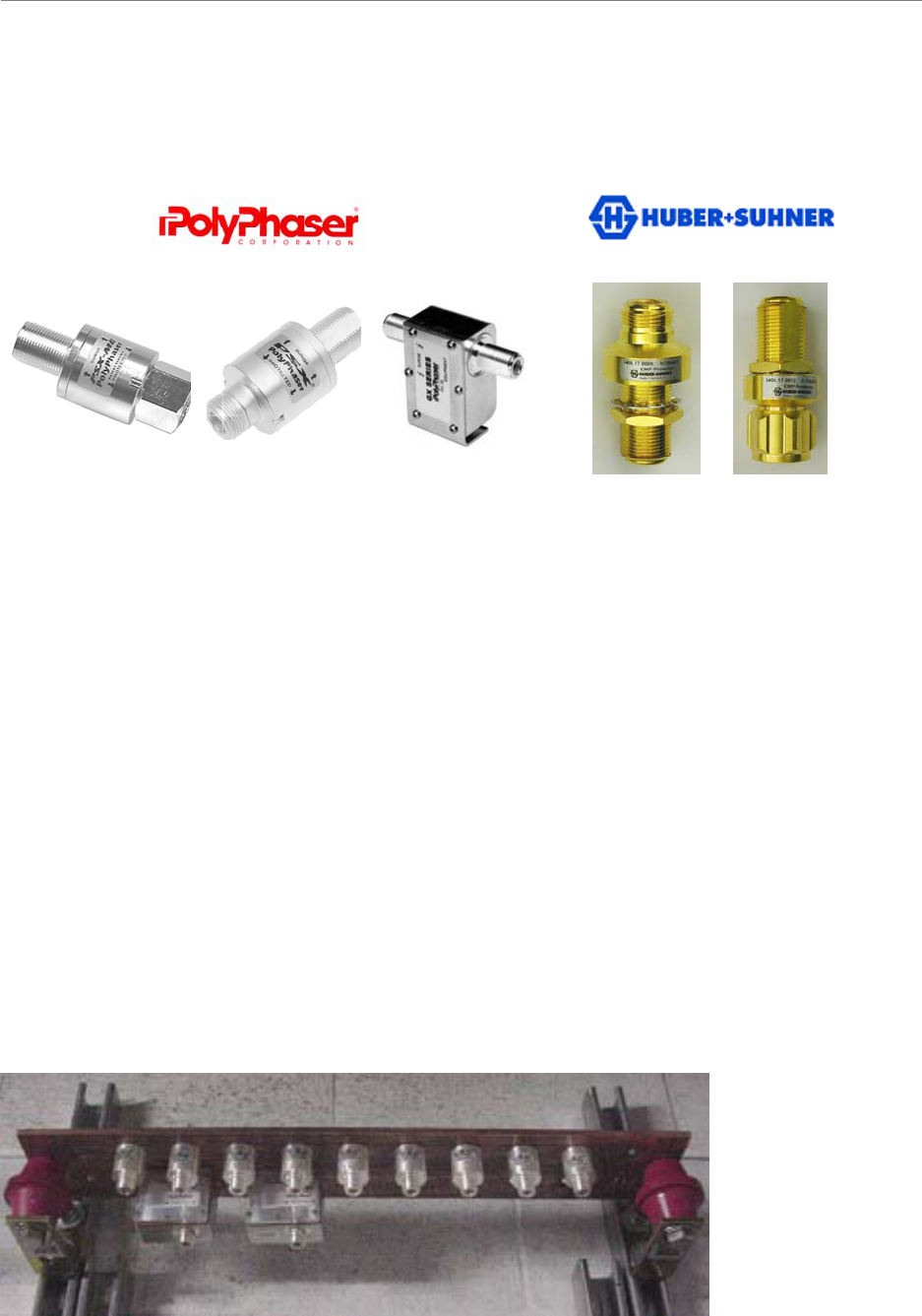
To install the eight (8) antenna and one (1) cal cable surge protectors (Figure 11), and the one (1)
or two (2) Global Positioning System (GPS) surge protectors (Figure 11) in the system ground
buss bar, follow the steps below.
1. Install the rubber gasket into the groove in the surge protector.
2. Install the surge protector in the system ground buss bar with the surge side toward the
antenna and the protected side toward the BTS.
3. Install the star washer and nut on the top of the surge protector. Torque the nut to 140-150
inch-pounds.
4. When finished, the mounted surge protectors in the buss bar will appear as in Figure 12.
CAUTION! Navini Networks provides both Secondary (built-in) and Primary
(optional) Lightning Protection. Lightning Protection helps to protect the RFS, the
BTS, and the RF lines against “tower lightning” events occurring at the Base Station.
The customer must exercise judgment when balancing risk against cost to decide
Navini Networks, Inc. Ripwave Base Station I&C Guide
46
whether to install the primary protection kit at an extra cost or to rely on the secondary
protection only. NOTE: Navini does not warranty equipment against lightning
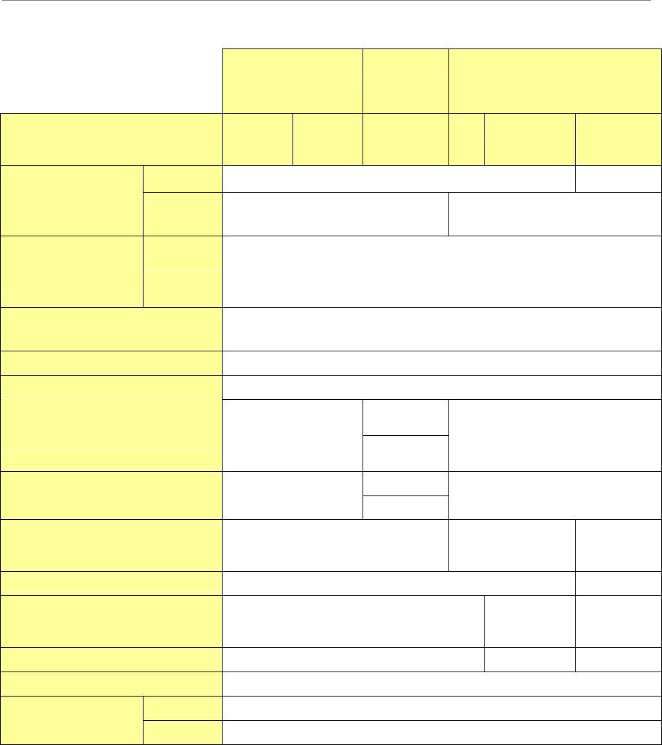
Figure 11: Surge Protectors
From left to right: PolyPhaser surge protectors are used with the Combo Chassis and Split
Chassis configurations (PSX-ME for the Cal and RF cables, at the antenna, PSX for the Cal and
RF cables at the ground Buss Bar, and DGXZ+06NFNF-A for the GPS antenna cable at the
ground Buss Bar.
Huber+Suhner surge protectors are used with TTA configurations. The Female-Female model is
used for Primary Surge protection* at the ground Buss Bar (RF and Cal cables near the BTS);
and the Male-Female model is used for Primary Surge protection (RF and Cal cables) at the RFS
and with the GPS cable.
PolyPhaser surge protectors block DC, are unidirectional (there is an “equipment side” and a
“line side”), have multi-strike capability, and have no gas tubes. Huber+Suhner surge protectors
allow the DC component that powers the PAs through but stop lightning surges and electrical
transients, are bi-directional, and have a gas discharge tube.
The Navini Part Numbers for the Huber+Suhner surge protectors are 32-00228-00 and 32-00229-
00, respectively. Similar surge protectors may be obtained from NexTek (Navini Part Numbers
32-00228-20 and 32-00229-20).
Figure 12: Surge Protectors in Buss Bar (Non-TTA system)
PSX-ME PSX DGXZ+06NFNF-A 3406.17.0012
3406.17.0009
PSX-MEPSX-ME PSXPSX DGXZ+06NFNF-ADGXZ+06NFNF-A 3406.17.0012
3406.17.00123406.17.00093406.17.0009
Navini Networks, Inc. Ripwave Base Station I&C Guide
47
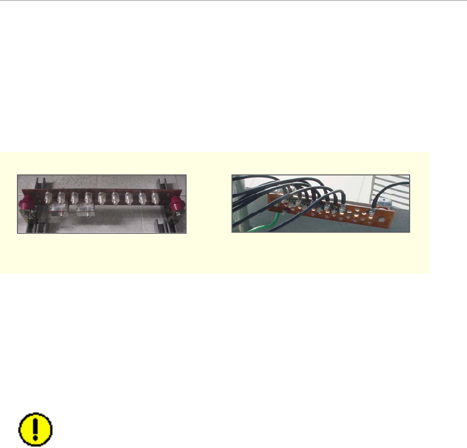
Antenna Ground Buss Bar
You should install the Antenna Ground Buss Bar on the mounting structure per accepted telecom
standards and procedures (Figure 13). The location is decided on during the site survey and
should be close to the RFS. Two or more buss bars may be installed per system.
Figure 13: Buss Bars
System Ground Wiring
A minimum #6 stranded, green-coated copper wire and grounding hardware are used for ground
connections. Install the system ground as a single-point connection between the system ground
buss bars, the data/power surge protector, the BTS chassis, the BTS mounting rack, and the RFS
antenna. Connect the system ground to earth ground. Apply anti-oxidant joint compound to all
connections (Figure 14). Tighten all connections until secure.
CAUTION! Without proper grounding a BTS is much more susceptible to
damage
Antenna Buss BarBTS Buss Bar Antenna Buss BarBTS Buss Bar

Navini Networks, Inc. Ripwave Base Station I&C Guide
48
Install Cables
All cable connections in the Combo and Split-Chassis configurations are made using standard
RF coaxial cable. The Navini Networks minimum for cable connections from the GPS to the
BTS is LMR 400, 3/8-inch coaxial cable. Other types of cable that are comparable may be used.
These were determined under “Antenna Power & Cable Selection” (Appendix H) activities cited
earlier. The TTA configuration uses a composite cable containing nine RG-6 or RG-11
individual strands to replace the 8 RF cables, the Cal cable and the Power/Data cable (the signal
previously sent through the Power/Data cable is now sent through the center connector of the
individual RG-6 or RG-11 strands).
All Coaxial and Digital cables between the Digital and RF shelves are 60 inches in length.
Physical distance between Digital and RF shelves will always be less than the cable length.
Figure 15: Coaxial Cables
HELIAX
RG-6 Bundle
RG6 RG11
HELIAX
RG-6 Bundle
RG6 RG11
HELIAX
RG-6 Bundle
RG6 RG11

Navini Networks, Inc. Ripwave Base Station I&C Guide
49
Cut Cables for the Combo and Split Chassis Configurations
The cable run is determined during the site survey. Note that the length of the cables may need to
be slightly different, depending on the position of the buss bar relative to the BTS.
• Cut nine (9) pieces of cable for the main feeder cables to connect the nine RFS
connectors to the surge protectors on the system ground buss bar. Leave enough extra
length for the service loop below the RFS and for connection to the surge protectors.
• Cut eight (8) pieces of cable for the jumper cables to connect the surge protectors on the
system ground buss bar to the eight (8) RF input connectors on the back of the BTS.
Leave enough extra cable length for service.
• Cut one (1) piece of cable for the jumper cable to connect the surge protector on the
system ground buss bar to the CAL connector on the back of the BTS. Leave enough
extra cable length for service.
• Cut a piece of LMR 400 cable to connect each of the GPS antennas to the surge
protectors on the system ground buss bar. Leave enough extra cable length for service.
The maximum loss for the cable to the GPS antenna is 11 dB.
• Cut a piece of LMR 400 cable to connect the surge protectors on the system ground buss
bar to each GPS connector on the back of the BTS. Leave enough extra cable length for
service. If there is more than one BTS co-located in the installation, two GPS antennas
can serve all BTSs in the installation.
• The cable from the GPS antenna (after it goes through the surge protector) is connected
to the antenna input of the GPS distribution amplifier (Figure 16). The output ports of the
GPS distribution amplifier are connected to the GPS inputs of the BTS. The GPS
distribution amplifier is powered by the GPS antenna input. The drawing in Figure 17
depicts the placement of the shared GPS resources among three BTSs.
CAUTION! GPS is required to prevent the BTSs in a network from
interfering with one another.