Cisco Systems 2305-BTS2-R1 Base Station Transmitter User Manual Ripwave Base Station I C Guide
Cisco Systems, Inc Base Station Transmitter Ripwave Base Station I C Guide
Contents
Manual part 5
Navini Networks, Inc. Ripwave Base Station I&C Guide
51
Bundle Cables for the TTA Configuration
The bundle cables are manufactured by CommScope in 5 m increments. On the end that attaches
to the antenna, the RG-6 or RG-11 bundle cables come with a weatherized “boot” and nine the
N-type Male connectors in place. At the other end, the connectors can be N-type, if the cables in
the will be connected to surge protectors in a buss bar (Primary Protection); or QMA, if the
cables are to be connected directly to the BTS (Secondary Protection only). In the first case, N-
type to QMA jumper cables are needed to connect the surge protectors in the buss bar to the
BTS.
You can optionally cut the bundle cable to the proper length, attach the connectors, and install
the boot on site by yourself. Use a torch to heat-shrink the boot, being careful not to burn it.
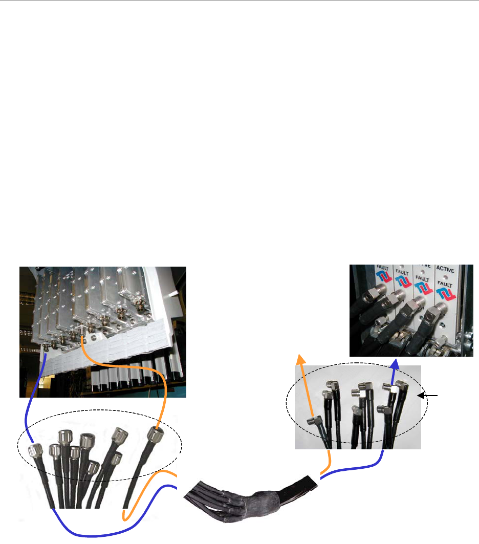
Figure 18 Bundle Cable, Weatherized “Boot” and End Connectors
Cal Port
(BTS back plane)
RFCs
(BTS front)
N-type
QMA
Cal Port
(BTS back plane)
RFCs
(BTS front)
N-type
QMA
Navini Networks, Inc. Ripwave Base Station I&C Guide
52
Install Connectors on Cables
Install connectors on both ends of each cable. For LMR 600 cables, install EZ-600 N-type male
connectors. For LMR 400 cables, install EZ-400 N-type male connectors. Steps for installing
both types of connectors can be found in Appendix J. For reference, Appendix H also provides a
list of vendors who can make cables.
The Cal and RF cables in the Combo and Split Chassis configuration have N-type male
connectors at both ends. The Bundle Cable used with the TTA configuration has N-type male
connectors at the antenna end, but the connectors used at the other end depend on the degree of
lightning protection desired. Is only the built-in protection is used, the connectors at the BTS
end are QMA male, but if the Ancillary surge protectors are used, the connectors at the BTS end
of this cable are N-type male.
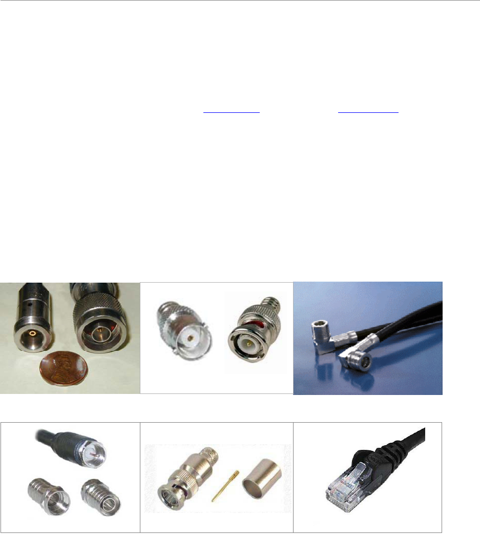
Figure 19: Connectors.
N-Type
FM
QMA
M
BNC
FM
RG6
Front Back
RG11 BNC RJ45/RJ48
N-Type
FM
QMA
M
BNC
FM
RG6
Front Back
RG11 BNC RJ45/RJ48
Navini Networks, Inc. Ripwave Base Station I&C Guide
53
Sweep RF Cables
Sweep each individual cable, the RFS (8) and CAL main feeder and jumper cables, to check for
line loss. Follow the instructions for sweeping the cables provided in Appendix K entering the
results in the RFS System Test Form. Check continuity of the data/power cable. When finished,
cover the cable connectors for protection until they are connected to the RFS or GPS.
Connectorize & Run Cables
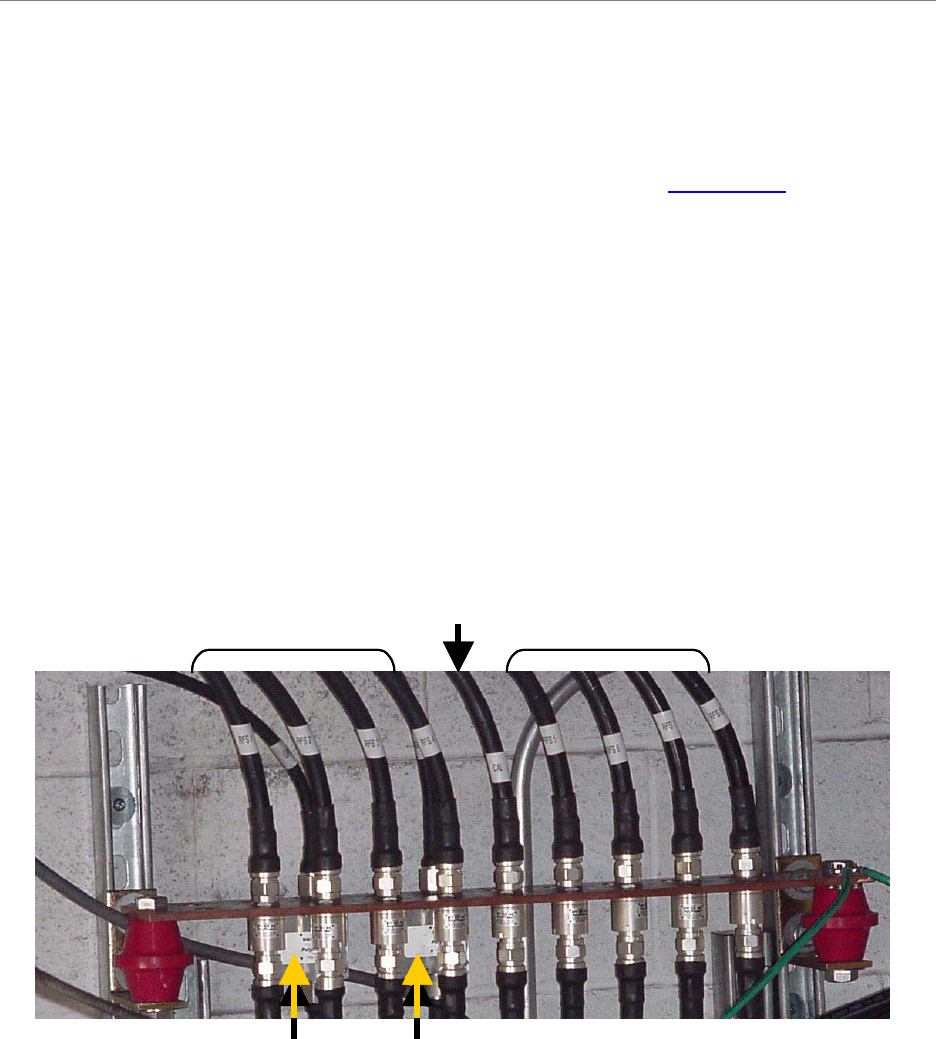
Connect all of the RF cables to the surge protectors in the system ground buss bar. An example
of a buss bar connection is shown in Figure 14. Ensure that the proper cable is connected to the
proper surge protector. Connect the power/data cable to its surge protector. Also connect all the
jumper cables to the surge protectors that will attach to the BTS. Do not connect these cables to
the BTS at this time. Torque all the cable connectors to the surge protectors on the system
ground buss bar to 20-24 inch-pounds.
Figure 20: Buss Bar Connections
Route all of the cables – RFS (8), CAL, DATA/POWER and GPS (1 or 2) - between the system
ground buss bar and the RFS, and GPS mounting sites. If running the cables up a tower, use a
hoisting grip to lift the cables.
GPS 1 GPS2
RF 1-4 RF 5-8
CAL
GPS 1 GPS2
RF 1-4 RF 5-8
CAL
Navini Networks, Inc. Ripwave Base Station I&C Guide
54
Install the BTS
Check all regulatory standards (refer to Chapter 1, Page 8 “Regulatory Information”) prior to
installation.
Install Mounting Rack or Enclosure
The BTS mounting rack (Figure 22) or enclosure is to be installed in compliance with applicable
portions of the National Electrical Code (NEC), articles 800 and 810. You will need to adhere to
local installation standards, as well as Navini Networks standards and procedures. Refer to
Appendix E for manufacturers of outdoor BTS enclosures.
Figure 22: BTS Mounting Racks
TTA ChassisTTA ChassisTTA ChassisTTA Chassis
Navini Networks, Inc. Ripwave Base Station I&C Guide
55
Install Chassis
There are three types of BTS chassis: Combo, Split and TTA (Figure 23). Prior to Ripwave
Release 1.19 (2.4 GHz systems), only the Combo Chassis was used, but with the licensed bands
(2.3, 2.5, and 2.6 GHz systems) it is allowed to transmit at higher levels of power, which
required better air circulation. This resulted in the introduction of the Split Chassis.
The recently introduced Tower Top Antenna (TTA) chassis, consists only of a digital shelf
because the PAs are incorporated into the base of the RFS. Notice that the TTA digital shelf
includes 8 new additional cards called RF Converters or RFC.
CAUTION! - Please contact Navini Technical support before attempting to
exchange cards between chassis of different type and frequency to verify
compatibility.
CAUTION! – In the TTA configurations, the RFCs output a +24 VDC current,
which is carried to the RFS through the RF Cables. This DC current may damage
test equipment connected directly to the RFC cards or to the end of the RF cables at
the RFS. When connecting test equipment to the output of the RFC card, an
external DC block may be required. Most signal generators and spectrum analyzers
cannot handle DC voltage on the I/O ports. Please, read the caution stickers on the
equipment and provide a DC block if the equipment cannot handle over "0"V DC.
Figure 23: BTS Chassis
TTA ChassisTTA ChassisTTA ChassisTTA Chassis

Navini Networks, Inc. Ripwave Base Station I&C Guide
56
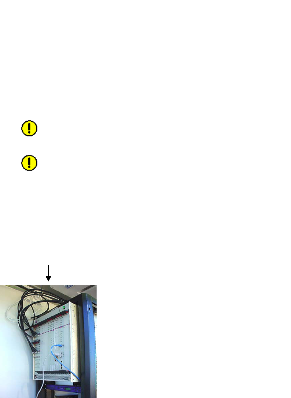
Connect Input Power
Next, connect the power supply to the BTS card cage (Figure 24). The gauge of the wire is
determined by the length of the run and by NEC/CEC standards (refer to Chapter 1, Page 8
“Regulatory Information”). Use a 60-amp circuit breaker when running the line. Terminate both
of the input power wires and the ground wire with a ¼- inch terminal lug. Assuming a +24 VDC
power supply, connect the +24 VDC input power connections and the +24 VDC return wires to
the BTS card cage.
WARNING! Ensure that the power is off before connecting the input power wires to the
BTS input terminals.
WARNING! Power supply range must be +24 ±3 VDC for TTA systems and
+24 +4/-3 VDC for Non-TTA Systems.
If the input power is 120 VAC, plug the two power-supply input cables into 120 VAC outlets,
and turn on the circuit breaker on the power supply. If the input power is 24 VDC, check for +24
VDC across the input terminals of the BTS card cage. If +24 VDC is not present across the input
terminals, check all input power wiring for proper connections. Also, check the power supply for
proper operation and the fuses for continuity.
When finished, turn off the power supply.
A drawing of the non-TTA tri-sectored grounding is provided in Appendix M, and the power for
the same type of system is shown in Appendix N.
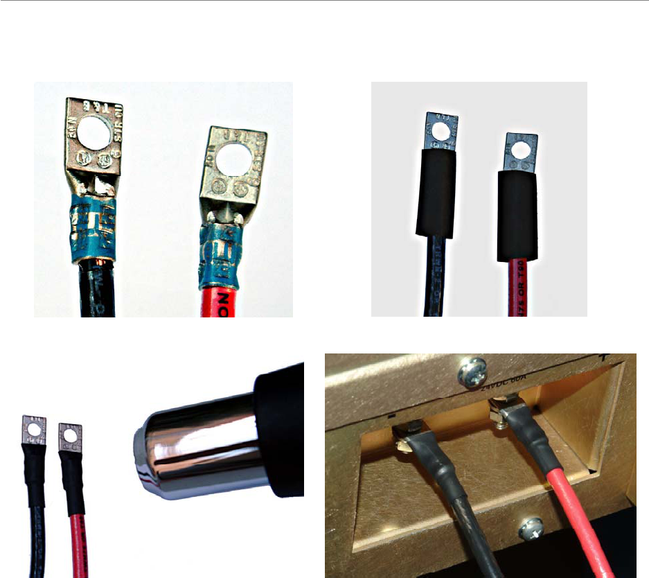
Power-interconnect wires between the power supply/rectifier and the digital chassis must have
heat shrink tubing applied over the barrel of the terminal lugs after crimping the wire. Refer to
Figure 25 below.
Figure 25: Power-Interconnect Wires
Navini Networks, Inc. Ripwave Base Station I&C Guide
57
Cooling Fans
Visually inspect all fans to ensure that they are operating properly.
1. Install UL-Listed Terminals 2. Slide on heat-shrink tubing
3. Apply heat to shrink tubing 4. Install power cables
1. Install UL-Listed Terminals 2. Slide on heat-shrink tubing
3. Apply heat to shrink tubing 4. Install power cables

Navini Networks, Inc. Ripwave Base Station I&C Guide
58
Connect BTS to Ground Connections
All connections need to be checked before power is applied to the system. At a minimum,
perform the following:
• Ensure continuity across all ground connections.
• Ensure an open connection from the power supply output (positive input to the BTS
card cage) to frame ground.
Check all regulatory standards (Chapter 1, Page 8 “Regulatory Information”) related to power
and grounding. All power and ground conductors must be mechanically supported to avoid strain
of the wires and connection points.
Connect Chassis Alarms
The chassis contains two connectors that are used to send alarm indications to the BTS when the
BTS is housed in an outdoor enclosure. One of the connectors, labeled “CABINET ALARM”, is
used to trigger alarm conditions that occur within the external chassis. The second connector,
labeled “BBU”, is used to process alarms from a battery backup unit. Refer to Appendix L for
instructions on connecting the alarms.

Navini Networks, Inc. Ripwave Base Station I&C Guide
59
Install GPS Antennas
Check all regulatory standards (refer to Chapter 1, Page 8 “Regulatory Information”) prior to
installation.
As mentioned earlier, the model of GPS antenna used with the Ripwave Base Station is the VIC
100, as shown in Figure 27.
Mount each GPS antenna module, run the cable through the pipe clamp mount. Connect the
cable to the GPS antenna, then, weatherize the connection. Secure the antenna module to the
pipe clamp mount using the captive mounting hardware. Install the GPS antenna module and the
pipe clamp mount to the mounting pipe and tighten the two mounting screws.
Make sure that the total loss from the GPS antenna to the SYN card in the BTS (including main
cable, jumper cable, splitter, lightning arrestor, etc.) does not exceed 11 dB.
The mounting location for the GPS antenna is determined during the site survey. When
installing, ensure that the following requirements are met:
• The voltage measured on the coax cable at the point at which the GPS antenna unit is
to be mounted (not at the rear of the BTS, but at the end of the cable run must be greater
than 4.5 Volts.
• The GPS antenna is located to provide the widest view of the sky (objects such as
buildings or trees can interfere with signals from the satellite).
• The number of satellites visible to the GPS antenna must be 6 or greater.
Navini Networks, Inc. Ripwave Base Station I&C Guide
60
Install the RFS
Check all regulatory standards (refer to Chapter 1, Page 8 “Regulatory Information”) prior to
installation. Now that the BTS is in place, the RFS is readied for installation. Follow the Panel or
Omni Antenna information and procedures below. Reference the specifications in Appendix D.
Also reference the RFS List/Hoist Method in Appendix X.
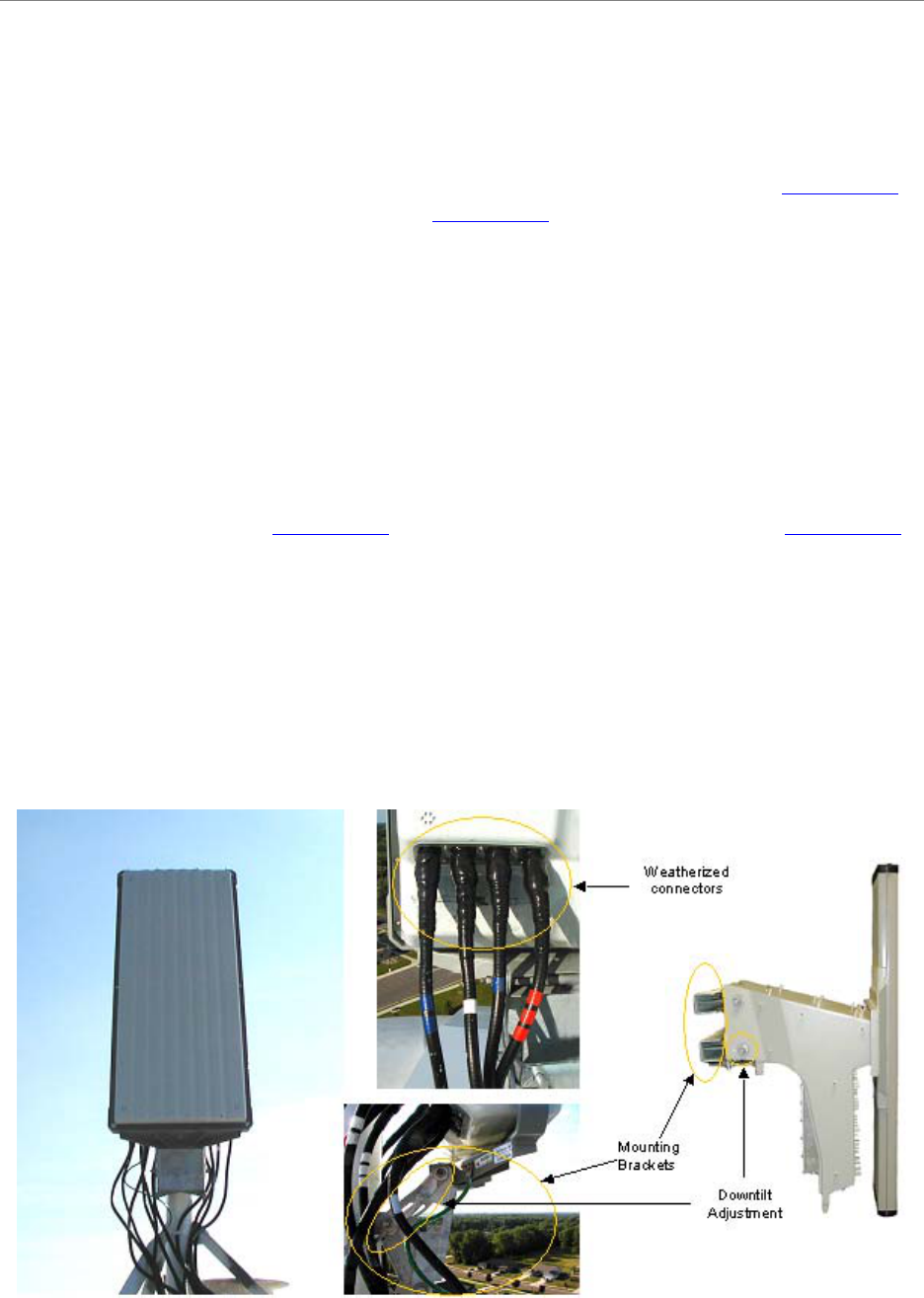
Panel Antenna
The RFS Panel antenna is installed on a structure, such as a tower or a pole, which is defined in
the site survey and design. Following are the steps to complete the installation of the panel
antenna.
Verify RFS Operation
Verify proper operation of the RFS before installation. Test the transmit and the receive path of
each antenna in the RFS per Appendix O, and using the RFS System Test Form in Appendix K.
Set the Downtilt
Check the engineering study for the required downtilt of the antenna. The panel antenna has 6o of
fixed electrical downtilt but it can be mechanically adjusted for an uptilt of 0 to 10o. As a result,
the main lobe of the beam can be pointed between 4 degrees above and 6 degrees below the
horizon.
Figure 28: Panel Antenna Elements

Navini Networks, Inc. Ripwave Base Station I&C Guide
61
Omni Antenna
An Omni antenna has 2 degrees of fixed electrical downtilt
Set the Azimuth
Position the RFS on the mounting pole or structure, ensuring that the antenna is pointing in the
proper azimuth direction determined by the engineering study. For an omni, the first antenna
element must face East (Figure 30).
The azimuth direction is stated in degrees from true North. Use the diagram shown in Figure 31
to determine the declination angle for your location. Add or subtract the declination angle from
magnetic North to obtain true North.
Tighten the four nuts on each of the two antenna mounting brackets to secure the RFS to the
mounting pole. Use a compass to check the direction from the center of the panel (this is
magnetic North). Be sure that you are using a compass calibrated for the geographical region
where you are. There are five such regions and a compass calibrated for one of them will not
work properly in the others.
Since this is not the year 2000 anymore, you will want to check this reference map to learn how
your magnetic declination shifts from year to year. Notice that the map measures annual shifts in
minutes. Since it takes 60 minutes to equal 1 degree, if you notice that your location has a
declination shift of 5 minutes per year, this means it will be another 12 years before your
declination adjustment changes by one whole degree. The following web site provides more
details on how to use these charts: http://www.thecompassstore.com/decvar.html
Verify the Downtilt
Using an inclinometer (Figure 32), check the downtilt of the RFS antenna. If required, adjust the
angle using the downtilt adjustment brackets. Be sure to include any electrical uptilt or downtilt
built into the antenna in the setting.
Tighten the mounting hardware to secure the RFS in the proper position. Recheck the downtilt
angle again to verify proper position. Repeat the procedure for all other antennas that are
installed in the system. Ensure that they are mounted in the proper direction and with the correct
downtilt angle.
Install Surge Protectors
If lightning protection is required, as determined by the customer, the power/data lightning
arrestors must comply with UL497. Cables, such as the RF and power/data cables, in excess of
140 feet in length must have protective devices installed that are UL497A or UL497B listed.
Navini Networks, Inc. Ripwave Base Station I&C Guide
62
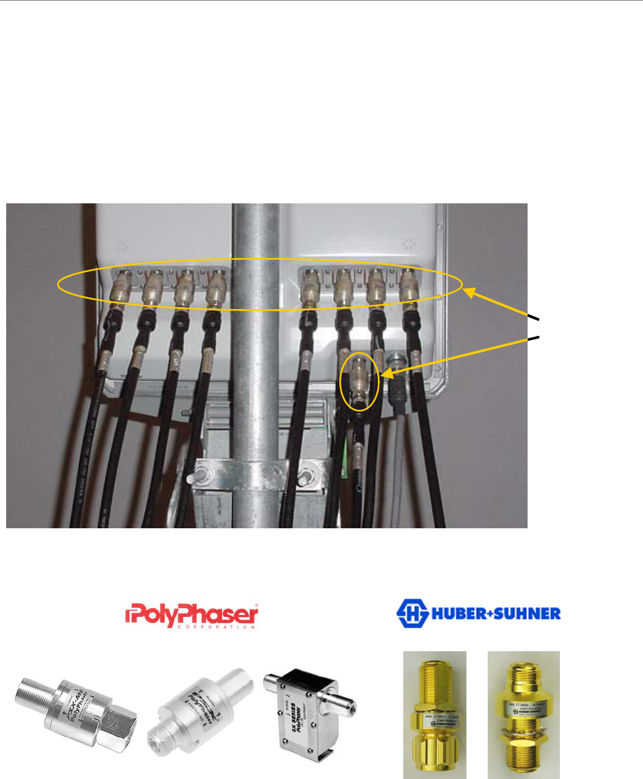
The RFS has ten cable connectors on the bottom of the unit. Eight are antenna connections, with
the connectors alternately numbered from right to left as shown in Figure 33. The two connectors
in the middle are for antenna calibration and data/DC power connections. Install surge protectors
on nine (9) of the RFS connectors – the eight antenna connectors and the calibration connector.
The surge protectors must be installed directly to the RFS to provide protection for the antenna
elements. Torque the surge protectors to 20-24 inch-pounds.
Figure 33: PolyPhaser PSX-ME Surge Protectors at the Antenna (RF and Cal Cables)
Figure 34: Surge Protectors
PSX-ME PSX DGXZ+06NFNF-A 3406.17.0012 3406.17.0009
PSX-MEPSX-ME PSXPSX DGXZ+06NFNF-A 3406.17.0012
3406.17.0012 3406.17.00093406.17.0009
62 5 184 7 3
Surge
Protectors
62 5 184 7 3
Surge
Protectors
Navini Networks, Inc. Ripwave Base Station I&C Guide
63
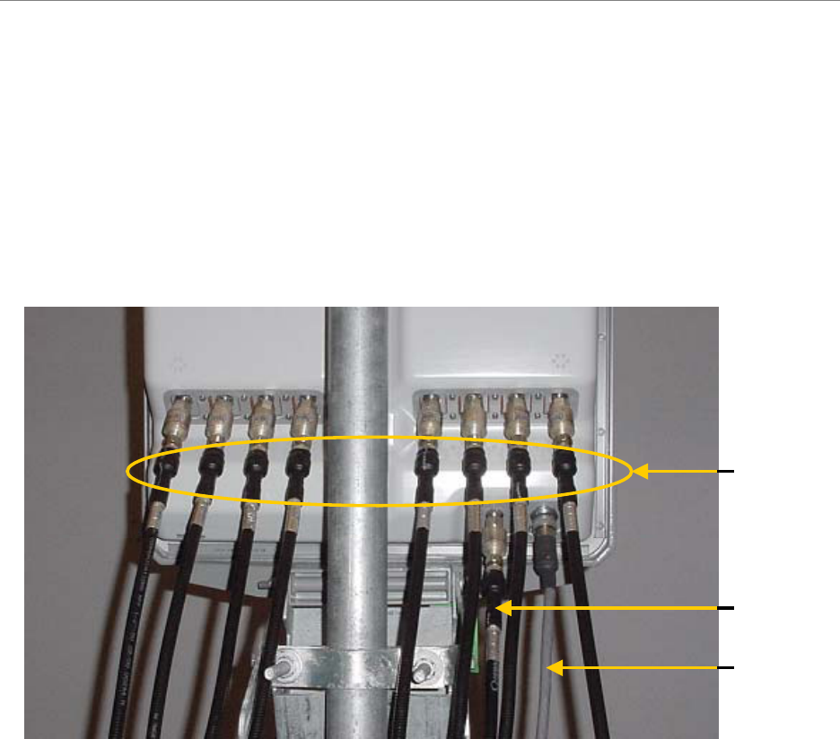
Install Cables Between the RFS & BTS
Connect all of the cables – the eight antenna cables, the calibration cable and the data/power
cable – to the surge protectors on the RFS. For ease of installation, install the cables from the
inside out. Ensure that the proper cable is connected to the proper antenna (Figure 35). Torque
the RF cable connectors to 20-24 inch-pounds.
Figure 35: Completed Cable Installation at the Antenna
Install Grounding Kit on Cables
Install grounding kit wire connections on the eight (8) RFS cables and the one (1) CAL cable per
the instruction sheet that comes with the grounding kit. Install the grounding wire in a position
on the cable so that it can be attached to the ground buss bar that is mounted close to the RFS.
More than one ground buss bar may be installed in the system, depending on the length of the
cable run. Reference the Regulatory Information in Chapter 1, Page 8.
62 5 184 7 3
Calibration
Cable
Data/Power
Cable
RF Cables
62 5 184 7 3
Calibration
Cable
Data/Power
Cable
RF Cables
Navini Networks, Inc. Ripwave Base Station I&C Guide
64
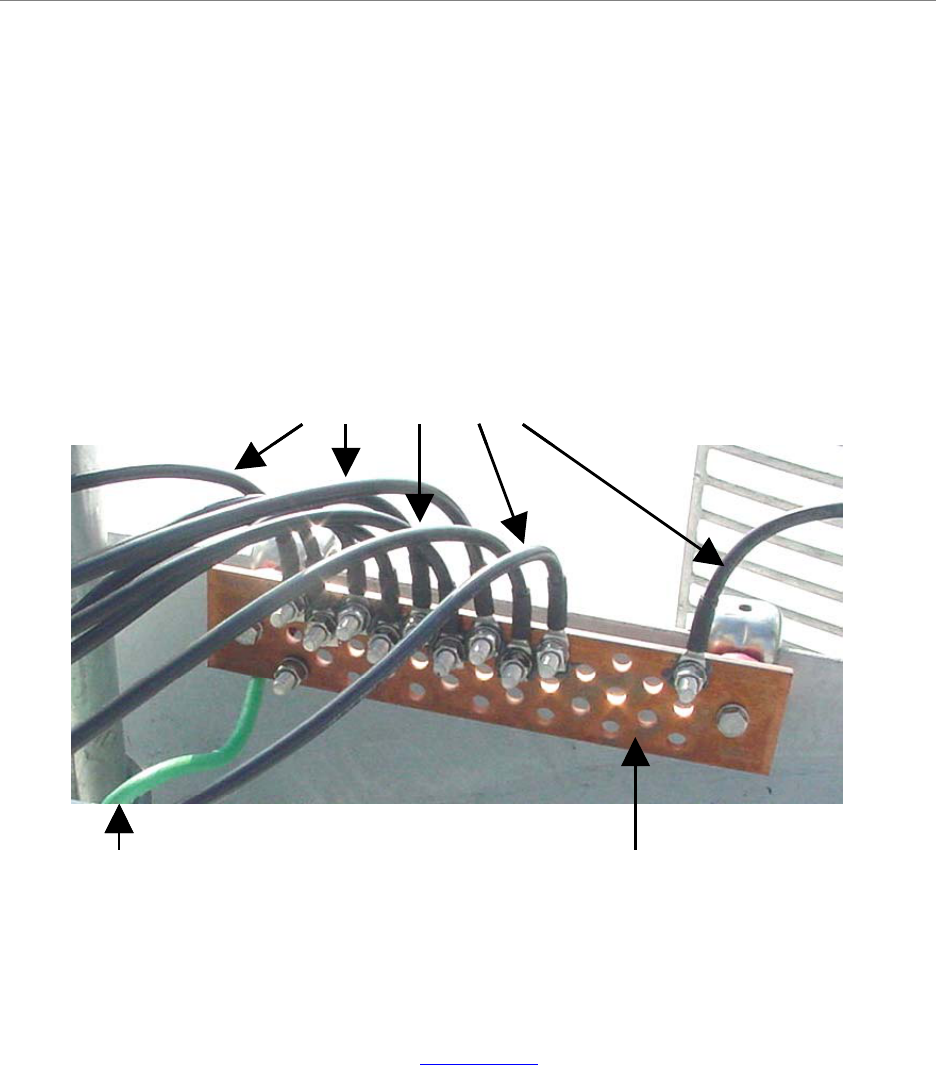
Connect Ground Wires to the Ground Buss Bar
Connect the ground wires on the cables to the ground buss bar using the hardware supplied with
the grounding kit. Connect the ground stud on the RFS to the ground buss bar. Use a ¼-inch
terminal lug to connect the ground wire to the ground stud on the RFS. Connect the ground buss
bar to earth ground. Grounding from copper point to copper point shall be less than 1 ohm.
Grounding from copper point to earth ground shall be less than 5 ohms. An example is shown in
Figure 36.
Figure 36: RFS Grounding
Test the RFS & Cables
Test the RFS and the eight (8) cables using Appendix K, the RFS System Test Form. Record the
results in the form. For this test, use the cable connectors that will be attached to the BTS.
Include the jumpers and all surge protectors.
Ground Buss Bar
Ground Wires
Earth Ground Ground Buss Bar
Ground Wires
Earth Ground
Navini Networks, Inc. Ripwave Base Station I&C Guide
65
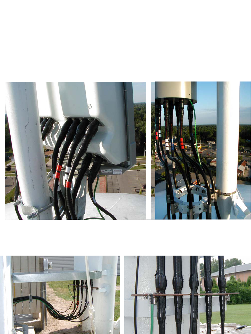
Weatherize the RFS Cable Connectors
Weatherize all ground wire connections exposed to weather using electrical tape and butyl
mastic tape. Follow the instructions supplied with the weatherproofing kit. Examples are shown
in Figure 37 and 38.
Figure 37: Weatherizing RFS Connectors Cables
Figure 38: Weatherizing Ground Wires