Cisco Systems IR529UWP IR529 915Mhz WPAN IP67 Range Extender User Manual
Cisco Systems Inc IR529 915Mhz WPAN IP67 Range Extender
Contents
- 1. Users Manual
- 2. Users manual 2
- 3. Users Manual 3
- 4. Users Manual 4
Users Manual 3

29/OCT/2014 REVIEW DRAFT — CISCO CONFIDENTIAL
Cisco Systems, Inc.
www.cisco.com
Cisco has more than 200 offices worldwide.
Addresses, phone numbers, and fax numbers
are listed on the Cisco website at
www.cisco.com/go/offices.
Cisco IR500 Series WPAN Gateway and
Range Extender Installation and
Configuration Guide
October 29, 2014 Revision
29/OCT/2014 REVIEW DRAFT — CISCO CONFIDENTIAL
THE SPECIFICATIONS AND INFORMATION REGARDING THE PRODUCTS IN THIS MANUAL ARE SUBJECT TO CHANGE WITHOUT NOTICE. ALL
STATEMENTS, INFORMATION, AND RECOMMENDATIONS IN THIS MANUAL ARE BELIEVED TO BE ACCURATE BUT ARE PRESENTED WITHOUT
WARRANTY OF ANY KIND, EXPRESS OR IMPLIED. USERS MUST TAKE FULL RESPONSIBILITY FOR THEIR APPLICATION OF ANY PRODUCTS.
THE SOFTWARE LICENSE AND LIMITED WARRANTY FOR THE ACCOMPANYING PRODUCT ARE SET FORTH IN THE INFORMATION PACKET THAT
SHIPPED WITH THE PRODUCT AND ARE INCORPORATED HEREIN BY THIS REFERENCE. IF YOU ARE UNABLE TO LOCATE THE SOFTWARE LICENSE
OR LIMITED WARRANTY, CONTACT YOUR CISCO REPRESENTATIVE FOR A COPY.
The following information is for FCC compliance of Class A devices: This equipment has been tested and found to comply with the limits for a Class A digital device, pursuant
to part 15 of the FCC rules. These limits are designed to provide reasonable protection against harmful interference when the equipment is operated in a commercial
environment. This equipment generates, uses, and can radiate radio-frequency energy and, if not installed and used in accordance with the instruction manual, may cause
harmful interference to radio communications. Operation of this equipment in a residential area is likely to cause harmful interference, in which case users will be required
to correct the interference at their own expense.
The following information is for FCC compliance of Class B devices: This equipment has been tested and found to comply with the limits for a Class B digital device, pursuant
to part 15 of the FCC rules. These limits are designed to provide reasonable protection against harmful interference in a residential installation. This equipment generates,
uses and can radiate radio frequency energy and, if not installed and used in accordance with the instructions, may cause harmful interference to radio communications.
However, there is no guarantee that interference will not occur in a particular installation. If the equipment causes interference to radio or television reception, which can be
determined by turning the equipment off and on, users are encouraged to try to correct the interference by using one or more of the following measures:
• Reorient or relocate the receiving antenna.
• Increase the separation between the equipment and receiver.
• Connect the equipment into an outlet on a circuit different from that to which the receiver is connected.
• Consult the dealer or an experienced radio/TV technician for help.
Modifications to this product not authorized by Cisco could void the FCC approval and negate your authority to operate the product.
The Cisco implementation of TCP header compression is an adaptation of a program developed by the University of California, Berkeley (UCB) as part of UCB’s public
domain version of the UNIX operating system. All rights reserved. Copyright © 1981, Regents of the University of California.
NOTWITHSTANDING ANY OTHER WARRANTY HEREIN, ALL DOCUMENT FILES AND SOFTWARE OF THESE SUPPLIERS ARE PROVIDED “AS IS” WITH
ALL FAULTS. CISCO AND THE ABOVE-NAMED SUPPLIERS DISCLAIM ALL WARRANTIES, EXPRESSED OR IMPLIED, INCLUDING, WITHOUT
LIMITATION, THOSE OF MERCHANTABILITY, FITNESS FOR A PARTICULAR PURPOSE AND NONINFRINGEMENT OR ARISING FROM A COURSE OF
DEALING, USAGE, OR TRADE PRACTICE.
IN NO EVENT SHALL CISCO OR ITS SUPPLIERS BE LIABLE FOR ANY INDIRECT, SPECIAL, CONSEQUENTIAL, OR INCIDENTAL DAMAGES, INCLUDING,
WITHOUT LIMITATION, LOST PROFITS OR LOSS OR DAMAGE TO DATA ARISING OUT OF THE USE OR INABILITY TO USE THIS MANUAL, EVEN IF CISCO
OR ITS SUPPLIERS HAVE BEEN ADVISED OF THE POSSIBILITY OF SUCH DAMAGES.
Cisco and the Cisco logo are trademarks or registered trademarks of Cisco and/or its affiliates in the U.S. and other countries. To view a list of Cisco trademarks, go to this
URL: www.cisco.com/go/trademarks. Third-party trademarks mentioned are the property of their respective owners. The use of the word partner does not imply a partnership
relationship between Cisco and any other company. (1110R)
Any Internet Protocol (IP) addresses and phone numbers used in this document are not intended to be actual addresses and phone numbers. Any examples, command display
output, network topology diagrams, and other figures included in the document are shown for illustrative purposes only. Any use of actual IP addresses or phone numbers in
illustrative content is unintentional and coincidental.
© 2014 Cisco Systems, Inc. All rights reserved.

iii
Cisco IR500 Series WPAN Gateway and Range Extender Installation and Configuration Guide
29/OCT/2014 REVIEW DRAFT — CISCO CONFIDENTIAL
CONTENTS
Preface ix
Audience ix
Conventions ix
Related Documents x
Obtaining Documentation and Submitting a Service Request xi
CHAPTER
1Overview 1-1
Features 1-1
WPAN Gateway Features 1-1
WPAN Range Extender Features 1-2
Models 1-2
WPAN Gateway Models 1-2
WPAN Range Extender Models 1-3
Assembly Details 1-3
Front Panel—WPAN Gateway 1-3
Status LEDS 1-4
Antenna Connector 1-4
RS232/RS485 DCE Port 1-5
RS232 DTE Port 1-5
USB Port 1-5
10/100 Fast Ethernet Port 1-5
Power and Alarm Connector 1-5
Reset Switch 1-6
Rear Panel—WPAN Gateway 1-6
Bottom Panel—WPAN Range Extender 1-7
Antenna Connector 1-10
Hard Points 1-10
Console Port 1-10
Protective Vent Port 1-11
Ground Connection 1-11
Power Connector 1-11
System LED 1-11
Top Panel—WPAN Range Extender 1-11

29/OCT/2014 REVIEW DRAFT — CISCO CONFIDENTIAL
Contents
iv
Cisco IR500 Series WPAN Gateway and Range Extender Installation and Configuration Guide
LEDs 1-12
WPAN Gateway LEDs 1-12
WPAN LED 1-13
RSSI LED 1-14
RS232-DCE LED 1-14
RS485 LED 1-14
USB LED 1-15
RS232-DTE LED 1-15
10/100 FE LED 1-15
Power LED 1-15
System LED 1-16
Alarm LED 1-16
WPAN Range Extender LEDs 1-16
Management Options 1-17
Connected Grid Network Management System 1-17
CSMP Client 1-18
Connected Grid Device Manager 1-18
CHAPTER
2Installation 2-1
Preparing for Installation 2-1
Warnings 2-1
Additional Information for Installation in a Hazardous Environment 2-3
Hazardous Locations Warnings for WPAN Gateway Only 2-3
North American Hazardous Location Approval for WPAN Gateway 2-5
EMC Environmental Conditions for Products Installed in the European Union 2-5
Tools and Hardware Required 2-5
WPAN Gateway Tools and Hardware Required 2-5
WPAN Range Extender Tools and Hardware Required 2-6
Unpacking the Components 2-6
WPAN Gateway Package Contents 2-6
Unpacking the WPAN Gateway 2-6
WPAN Range Extender Package Contents 2-7
Unpacking the WPAN Range Extender 2-7
Installation Guidelines 2-7
Site Surveys 2-8
Becoming Familiar with WPAN Gateway and WPAN Range Extender Installation Options and
Components 2-8
WPAN Gateway Installation Options and Components 2-8
WPAN Range Extender Installation Options and Components 2-8

29/OCT/2014 REVIEW DRAFT — CISCO CONFIDENTIAL
Contents
v
Cisco IR500 Series WPAN Gateway and Range Extender Installation and Configuration Guide
Installing the Devices 2-9
Mounting the WPAN Gateway 2-9
Mounting the WPAN Gateway on a DIN Rail 2-9
Mounting the WPAN Gateway on a Wall 2-13
Mounting the Range Extender 2-15
Mounting the Range Extender on a Pole 2-15
Connecting the Protective Ground and Power 2-18
Grounding the WPAN Gateway 2-18
Wiring the WPAN Gateway DC Power 2-20
Grounding the WPAN Range Extender 2-24
Wiring the WPAN Range Extender AC Power 2-27
Wiring the Alarm Circuits 2-29
Wiring the WPAN Gateway Alarm 2-29
Attaching the Power and Alarm Connector to the WPAN Gateway 2-31
Connecting to Device Ports 2-33
Connecting to WPAN Gateway Ports 2-33
Connecting to the RS232DCE/RS485 or RS232-DTE Ports 2-33
Connecting to the 10/100 Fast Ethernet Port 2-34
Connecting to the USB Port 2-35
Connecting to the Console Port 2-36
Connecting to WPAN Range Extender Ports 2-37
Connecting to the Console Port 2-37
CHAPTER
3Battery Backup Unit 3-1
Battery Backup Units 3-1
WPAN Range Extender Models Supporting BBUs 3-1
Battery Backup Operations 3-2
BBU Status 3-2
Battery Backup Mode 3-2
Range Extender Configuration 3-3
Range Extender Interface Operation 3-3
BBU Firmware Upgrade 3-3
BBU Configuration during Transportation 3-4
Setting the BBU NVRAM Register T-bit 3-4
BBU NVRAM Register T-bit Settings and BBU Status 3-4
Disabling and Enabling the BBU in the Range Extender 3-4
Disabling the BBU 3-5
Enabling the BBU 3-5
Installing a BBU in the Range Extender 3-5

29/OCT/2014 REVIEW DRAFT — CISCO CONFIDENTIAL
Contents
vi
Cisco IR500 Series WPAN Gateway and Range Extender Installation and Configuration Guide
BBU Technical Specifications 3-5
Range Extender Power Path Selection 3-5
Discharge Conditions 3-6
Charge Conditions 3-6
Operating and Storage Temperatures 3-7
Battery Life 3-7
CHAPTER
4Antenna 4-1
Antennas Overview 4-1
WPAN Gateway Antenna Configurations 4-1
Gateway Pole Mounted Antenna with Below Grade Conduit Routed Cabling Configuration 4-2
Gateway Enclosure Mounted Antenna Configuration 4-3
Gateway Pole Mounted Antenna with Enclosure Interface Lightning Arrestor Configuration 4-4
WPAN Range Extender Antenna Configurations 4-4
Basic Range Extender Antenna Configuration 4-5
Single Antenna Advanced Range Extender—Direct Connect Antenna Configuration 4-5
Single Antenna Advanced Range Extender—Pole Mounted Antenna Configuration 4-6
Dual Antenna Advanced Range Extender—Dual Antenna Configuration 4-6
Additional Information for WPAN Gateway Antenna Installations 4-7
Installing or Replacing Antennas 4-7
CHAPTER
5Operation and Configuration 5-1
Information about WPAN Gateway and WPAN Range Extender Operation 5-1
WPAN Gateway and WPAN Range Extender and the Cisco Field Area Network 5-1
Role of the WPAN Gateway and WPAN Range Extender in the Cisco FAN 5-2
Role of the WPAN Gateway 5-2
Role of the WPAN Range Extender 5-3
WPAN Gateway and WPAN Range Extender Data Flow 5-3
Data Flow Prerequisites 5-3
Data Flow Paradigms 5-4
Information about Raw Socket Transport and MAP-T 5-5
Raw Socket 5-5
TCP Transport 5-5
Raw Socket Configurations 5-6
Raw Socket and Serial Protocol Operation 5-7
MAP-T 5-8
MAP-T Mapping Rules and Map Domain Parameters 5-9
MAP-T Addressing Rules Example 5-10
Information about WPAN Gateway and WPAN Range Extender Configuration 5-11

29/OCT/2014 REVIEW DRAFT — CISCO CONFIDENTIAL
Contents
vii
Cisco IR500 Series WPAN Gateway and Range Extender Installation and Configuration Guide
Role of CG-NMS 5-11
CG-NMS Device Classification 5-11
CSMP Client 5-12
Role of CG-DM 5-12
Configuring the WPAN Gateway and WPAN Range Extender 5-12
Accessing the Configuration through the Console Port 5-12
Connecting to the WPAN Gateway Console Port 5-13
Connecting to the WPAN Range Extender Console Port 5-13
Uploading a Device to CG-NMS 5-16
Registering with CG-NMS 5-17
Configuring an IR 500 Series Device with CG-NMS 5-17
Configuring Serial Interface Settings 5-17
Configuring MAP-T Settings 5-18
Configuring Raw Socket Settings 5-18
Configuring Mesh Link Settings 5-19
Configuring NAT44 5-19
Related CGR 1000 and ASR 1000 Configurations 5-19
Configuring Raw Socket Configuration on CGR 1000 Series and CGR 2010 Routers 5-19
Configuring the WPAN Settings on CGR 1000 Series Routers 5-20
Configuring an IPv6 DHCP Address Pool on CGR 1000 Series Routers 5-20
Configuring MAP-T on ASR 1000 Routers 5-20
Configuring IPv6 Routing on the CGR 1000 Series and ASR 1000 Routers 5-20
CG-NMS WPAN Device Management Related Operations 5-20
Performing Periodic Inventory 5-21
Uploading Firmware 5-22
Creating Rules and Events 5-22
APPENDIX
ATechnical Specifications A-1
Environmental and Operational Specifications A-1
WPAN Gateway Environmental and Operational Specifications A-1
WPAN Range Extender Environmental and Operational Specifications A-2
Basic Range Extender A-2
Advanced Range Extender A-2
Power Specifications A-3
WPAN Gateway Power Requirements A-3
WPAN Range Extender Power Requirements A-3
Alarm Ratings A-3
Mechanical Specifications A-4
WPAN Gateway Mechanical Specifications A-4

29/OCT/2014 REVIEW DRAFT — CISCO CONFIDENTIAL
Contents
viii
Cisco IR500 Series WPAN Gateway and Range Extender Installation and Configuration Guide
WPAN Range Extender Mechanical Specifications A-4
Hazardous Location Specifications A-5
Declaration of Conformity for RF Exposure A-5
United States A-5
Canada A-5
APPENDIX
BCable and Connectors B-1
Connector Specifications B-1
WPAN Gateway Power and Alarm Connector B-1
WPAN Gateway Console Port B-2
WPAN Gateway RS232/RS485 DCE Serial Port B-2
WPAN Gateway RS232 DTE Serial Port B-3
WPAN Gateway USB Port B-3
WPAN Gateway 10/100 Fast Ethernet Port B-4
WPAN Range Extender Power Connector B-4
WPAN Range Extender Console Port B-5
Cables and Adapters B-5
WPAN Gateway and WPAN Range Extender Console Port Adapter Pinouts B-5

29/OCT/2014 REVIEW DRAFT — CISCO CONFIDENTIAL
ix
Cisco IR500 Series WPAN Gateway and Range Extender Installation and Configuration Guide
Preface
Audience
This guide is for the networking or computer technician responsible for installing and configuring
WPAN gateway and WPAN range extender devices.
Conventions
This document uses the following conventions:
Convention Indication
bold font Commands and keywords and user-entered text appear in bold font.
italic font Document titles, new or emphasized terms, and arguments for which you supply
values are in italic font.
[ ] Elements in square brackets are optional.
{x | y | z } Required alternative keywords are grouped in braces and separated by
vertical bars.
[ x | y | z ] Optional alternative keywords are grouped in brackets and separated by
vertical bars.
string A nonquoted set of characters. Do not use quotation marks around the string or
the string will include the quotation marks.
courier font Terminal sessions and information the system displays appear in courier font.
< > Nonprinting characters such as passwords are in angle brackets.
[ ] Default responses to system prompts are in square brackets.
!, # An exclamation point (!) or a pound sign (#) at the beginning of a line of code
indicates a comment line.
Note Means reader take note. Notes contain helpful suggestions or references to material not covered in the
manual.

29/OCT/2014 REVIEW DRAFT — CISCO CONFIDENTIAL
x
Cisco IR500 Series WPAN Gateway and Range Extender Installation and Configuration Guide
Tip Means the following information will help you solve a problem. The tips information might not be
troubleshooting or even an action, but could be useful information, similar to a Timesaver.
Caution Means reader be careful. In this situation, you might perform an action that could result in equipment
damage or loss of data.
Timesaver Means the described action saves time. You can save time by performing the action described in
the paragraph.
Warning
IMPORTANT SAFETY INSTRUCTIONS
This warning symbol means danger. You are in a situation that could cause bodily injury. Before you
work on any equipment, be aware of the hazards involved with electrical circuitry and be familiar
with standard practices for preventing accidents. Use the statement number provided at the end of
each warning to locate its translation in the translated safety warnings that accompanied this device.
SAVE THESE INSTRUCTIONS
Warning
Statements using this symbol are provided for additional information and to comply with regulatory
and customer requirements.
Related Documents
Before installing, configuring, or upgrading the WPAN gateway or WPAN range extender, see the
release notes on Cisco.com for the latest information.
The following documents relate to the deployment of the WPAN gateway and WPAN range extender:
• Cisco Connected Grid Network Management System User Guide. Contact Cisco for a copy of this
document.
• Cisco Connected Grid WPAN Module for CGR 1000 Series Installation and CG-Mesh Configuration
Guide
• "Mapping of Address and Port Using Translation" chapter of Cisco Systems, Inc. IP Addressing:
NAT Configuration Guide, Cisco IOS XE Release 3S (ASR 1000)
• Raw Socket Transport Software Configuration Guide for Cisco 1000 Series Connected Grid Routers
(Cisco IOS)

29/OCT/2014 REVIEW DRAFT — CISCO CONFIDENTIAL
xi
Cisco IR500 Series WPAN Gateway and Range Extender Installation and Configuration Guide
Obtaining Documentation and Submitting a Service Request
For information on obtaining documentation, using the Cisco Bug Search Tool (BST), submitting a
service request, and gathering additional information, see What’s New in Cisco Product Documentation
at: http://www.cisco.com/en/US/docs/general/whatsnew/whatsnew.html.
Subscribe to What’s New in Cisco Product Documentation, which lists all new and revised Cisco technical
documentation, as an RSS feed and deliver content directly to your desktop using a reader application. The
RSS feeds are a free service.

29/OCT/2014 REVIEW DRAFT — CISCO CONFIDENTIAL
xii
Cisco IR500 Series WPAN Gateway and Range Extender Installation and Configuration Guide

CHAPTER
29/OCT/2014 REVIEW DRAFT — CISCO CONFIDENTIAL
1-1
Cisco IR500 Series WPAN Gateway and Range Extender Installation and Configuration Guide
1
Overview
This chapter includes the following topics:
• Features, page 1-1
• Models, page 1-2
• Assembly Details, page 1-3
• LEDs, page 1-12
• Management Options, page 1-17
• Management Options, page 1-17
Features
• WPAN Gateway Features, page 1-1
• WPAN Range Extender Features, page 1-2
WPAN Gateway Features
The WPAN Gateway provides secure network connectivity over 6LoWPAN/RPL/IEEE 802.15.4g/e
subnets to field devices equipped with Ethernet and serial adapters. The device features:
Its main characteristics are:
• Small form factor IEEE 802.15.4g/e 902-928 MHz frequency band operation
• Network Backhaul Interface
–
1 x IEEE 802.15.4g/e WPAN 902-928 MHz Mesh interface
• Network Device Interfaces
–
1 x 10/100 Fast Ethernet
–
1 x RS232 Serial port
–
1 x USB port
–
1 x RS232/RS485 Serial port
–
1 x Console port
• Alarm input

29/OCT/2014 REVIEW DRAFT — CISCO CONFIDENTIAL
1-2
Cisco IR500 Series WPAN Gateway and Range Extender Installation and Configuration Guide
Chapter 1 Overview
Models
• 6LoWPAN (RFC4944 and RFC6282)—IPv6 adaptation layer
• RPL (RFC 6206, 6550, 6551, 6553, 6554, 6719)—Layer-3 Mesh Networking
• IEEE 802.1x and 802.11i—Authentication and Key Management
• Constrained Application Protocol (CoAP) and CoAP Secure Management Policy (CSMP) Network
Management
• Raw Socket TCP—non-IP serial devices connectivity
• Real-Time Clock—for maintaining the current time
• Temperature Sensor—for measuring internal temperature of the device
• IP30 enclosure
WPAN Range Extender Features
The WPAN range extender extends the range of an RF wireless mesh network, providing longer reach
between WPAN endpoints and other WPAN networks.
WPAN range extenders support the full CG-Mesh network platform, including IEEE 802.15.4g/e, IEEE
802.1X, IPv6, and RPL.
The WPAN range extender features:
• Small form factor IEEE 802.15.4g/e 902-928 MHz frequency band operation
• 1 x Serial console port for configuration and management
• Real-Time Clock—for maintaining the current time
• Temperature Sensor—for measuring internal temperature of the device
• Ruggedized IP67 outdoor enclosure
• Optional battery backup
Models
• WPAN Gateway Models, page 1-2
• WPAN Range Extender Models, page 1-3
WPAN Gateway Models
Table 1-1 lists and describes the WPAN gateway models.

Table 1-1 WPAN Gateway Models
Model Description
IR509U-WP-915/K9 The IR509U-WP-915/K9 model includes:
• IEEE 802.15.4g/e WPAN 902-928 MHz mesh interface
• 10/100 Fast Ethernet port
• RS232 serial port
• RS232/RS485 serial port
• USB port
• Configurable alarm input (normally open or normally closed setup)
• IP30 enclosure
29/OCT/2014 REVIEW DRAFT — CISCO CONFIDENTIAL
1-3
Cisco IR500 Series WPAN Gateway and Range Extender Installation and Configuration Guide
Chapter 1 Overview Assembly Details
WPAN Range Extender Models
Table 1-2 lists and describes the WPAN range extender models.
Table 1-2 WPAN Range Extender Models
Model Description
IR529-WP-915S/K9 Connected Grid Basic Range Extender—IEEE 802.15.4e/g WPAN
900 MHz
IR529-UBWP-915S/K9 Connected Grid Advanced Range Extender, configurable with single
antenna and battery backup support—IEEE 802.15.4e/g WPAN 900 MHz
IR529-UBWP-915D/K9 Connected Grid Advanced Range Extender, configurable with dual antenna
and battery backup support—IEEE 802.15.4e/g WPAN 900 MHz
IR529-UWP-915D/K9 Connected Grid Advanced Range Extender, configurable with dual
antenna—IEEE 802.15.4e/g WPAN 900 MHz
Assembly Details
• Front Panel—WPAN Gateway, page 1-3
• Rear Panel—WPAN Gateway, page 1-6
• Bottom Panel—WPAN Range Extender, page 1-7
• Top Panel—WPAN Range Extender, page 1-11
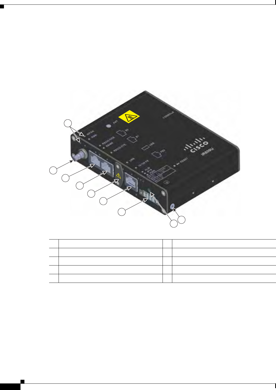
Front Panel—WPAN Gateway
This section describes the front panel components shown in Figure 1-1:
• Status LEDS, page 1-4
• Antenna Connector, page 1-4
• RS232/RS485 DCE Port, page 1-5
29/OCT/2014 REVIEW DRAFT — CISCO CONFIDENTIAL
1-4
Cisco IR500 Series WPAN Gateway and Range Extender Installation and Configuration Guide
Chapter 1 Overview
Assembly Details
• RS232 DTE Port, page 1-5
• USB Port, page 1-5
• 10/100 Fast Ethernet Port, page 1-5
• Power and Alarm Connector, page 1-5
• Reset Switch, page 1-6
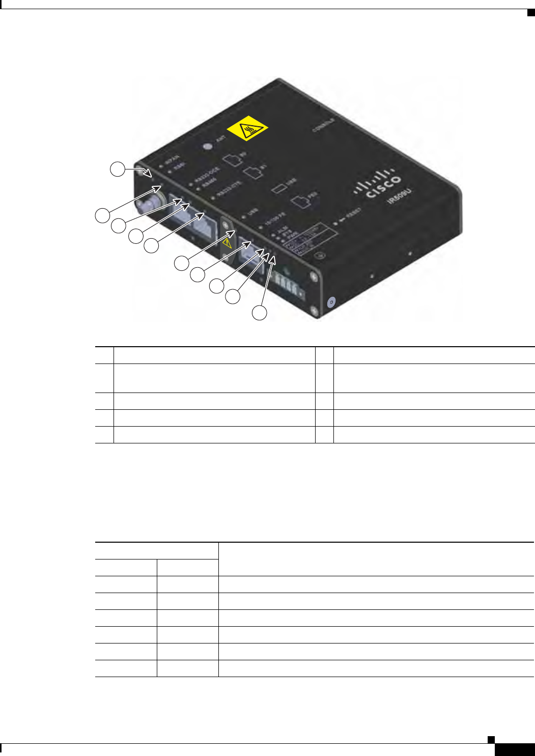
Figure 1-1 Front Panel of WPAN Gateway IR509U-WP-915/K9 Model
1
2
3
4
6
7
8
390980
5
9
1Status LEDs 610/100 Fast Ethernet port
2Antenna connector 7Power1
1. DC power.
and alarm connector
3RS232-DCE/RS485 selectable port 8Reset button
4RS232-DTE port 9Ground connection point
5USB port
Status LEDS
The status LEDs provide status information on the WPAN gateway status, activity, and performance. For
more information, see the “WPAN Gateway LEDs” section on page 1-12.
Antenna Connector
The antenna connector is a QMA, panel-mounted, 50-ohm connector for connecting the antenna to the
WPAN gateway.

29/OCT/2014 REVIEW DRAFT — CISCO CONFIDENTIAL
1-5
Cisco IR500 Series WPAN Gateway and Range Extender Installation and Configuration Guide
Chapter 1 Overview Assembly Details
RS232/RS485 DCE Port
The RS232/RS485 DCE port is a configurable serial port for connecting a serial device to the WPAN
Gateway. The Connected Grid Network Management System (CG-NMS) application is used to configure
the port.
The port can be configured for RS232 or RS485. RS232 operates in full duplex mode on the port, and
RS485 operates in half duplex or full duplex mode. You can also use the CG-NMS to obtain statistics
about the serial port including bytes sent and bytes received information.
For information about connecting to the RS232-DCE or RS485 port, see the “Connecting to the
RS232DCE/RS485 or RS232-DTE Ports” section on page 2-33.
RS232 DTE Port
The RS232 DTE port is a configurable serial port for connecting a serial device to the WPAN Gateway.
The Connected Grid Network Management System (CG-NMS) application is used to configure the port.
You can also use the CG-NMS to obtain statistics about the port including bytes sent and bytes received
information.
For information about connecting to the RS232 DTE port, see the “Connecting to the RS232DCE/RS485
or RS232-DTE Ports” section on page 2-33.
USB Port
For information about the USB port, see the Cisco IR 500 Series WPAN Gateway and Range Extender
Release Notes on Cisco.com.
For information about connecting to the USB port, see the “Connecting to the USB Port” section on
page 2-35.
10/100 Fast Ethernet Port
The 10/100 Fast Ethernet port provides IPv4 connectivity to devices. Connectivity over the IPv6-based
Field Area Network (FAN) is provided using the Mapping of Address and Port using Translation
(MAP-T) protocol by the WPAN gateway.
For information about connecting to the Fast Ethernet 10/100 port, see the “Connecting to the 10/100
Fast Ethernet Port” section on page 2-34.
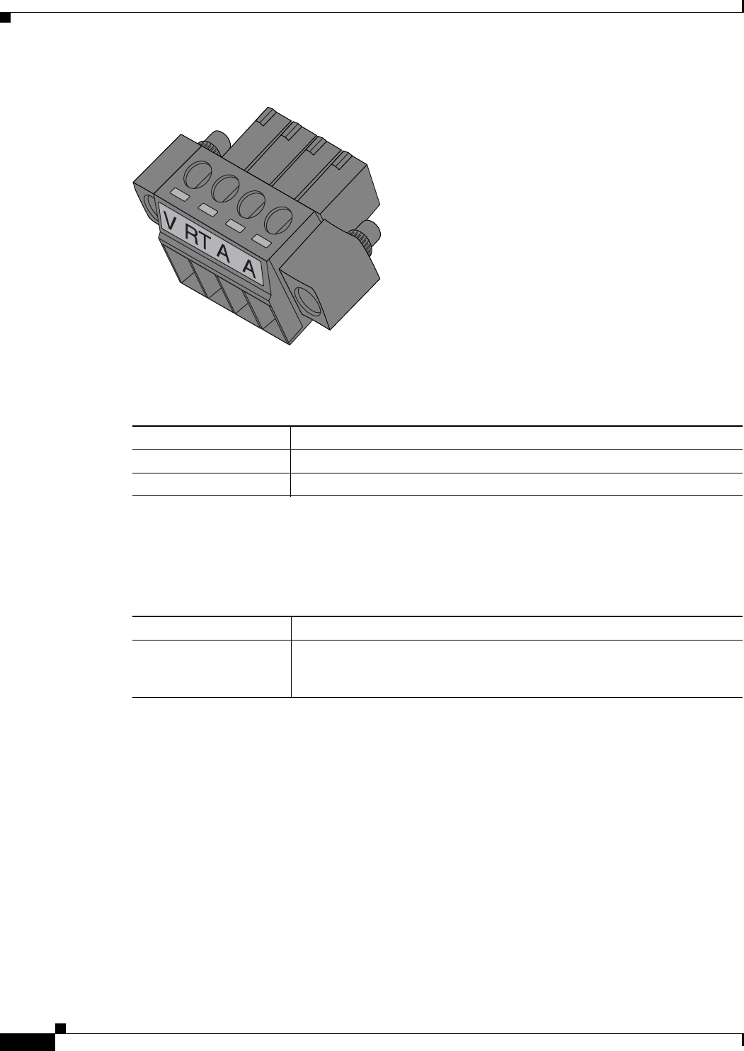
Power and Alarm Connector
You connect the DC power and alarm connections to the WPAN gateway through the front panel
connector. The gateway requires a DC power supply. The power connector labeling is on the connector.
Figure 1-2 shows the power and alarm connector.
29/OCT/2014 REVIEW DRAFT — CISCO CONFIDENTIAL
1-6
Cisco IR500 Series WPAN Gateway and Range Extender Installation and Configuration Guide
Chapter 1 Overview
Assembly Details
Figure 1-2 WPAN Gateway Power and Alarm Connector
391216
Table 1-3 describes the power connections.
Table 1-3 WPAN Gateway Power Connections
Label Description
VPositive DC power connection
RT Return DC power connection
The alarm input connections allow the WPAN gateway to be wired to monitor an alarm condition. The
alarm can be configured by the Connected Grid Network Management System to operate on a normally
open (NO) or normally closed (NC) basis. Table 1-4 describes the alarm connections.
Table 1-4 Alarm Connections
Label Description
AEach alarm connection is labeled identically—this means each connection
can be an ‘Alarm in’ or ‘Alarm reference’ signal, provided the second alarm
connection provides the other alarm signal.
The alarm input could be used to detect a remote alarm condition such as a normally locked cabinet door
being opened or tampered with, or an attached electromechanical device losing power.
For information about wiring the power and alarm connector, see the “Wiring the WPAN Gateway DC
Power” section on page 2-20 and the “Wiring the WPAN Gateway Alarm” section on page 2-29.
Reset Switch
The reset switch is used to rest the WPAN gateway to its factory settings. To activate the reset, press the
reset switch for three seconds.
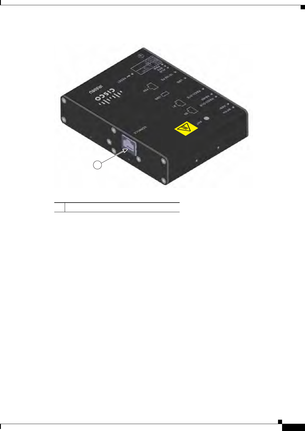
Rear Panel—WPAN Gateway
This section describes the WPAN gateway rear panel components shown in Figure 1-3:
29/OCT/2014 REVIEW DRAFT — CISCO CONFIDENTIAL
1-7
Cisco IR500 Series WPAN Gateway and Range Extender Installation and Configuration Guide
Chapter 1 Overview Assembly Details
Figure 1-3 Rear Panel of WPAN Gateway IR509U-WP-915/K9 Model
390981
1
1Console port
You can connect the WPAN gateway to a PC or laptop through the RJ-45 console port. The RJ-45 console
port uses the Cisco Console Port RJ45-to-DB9 cable (Cisco part number 72-3383-01).
For information about connecting to the console port, see the “Connecting to the WPAN Gateway
Console Port” section on page 5-13.
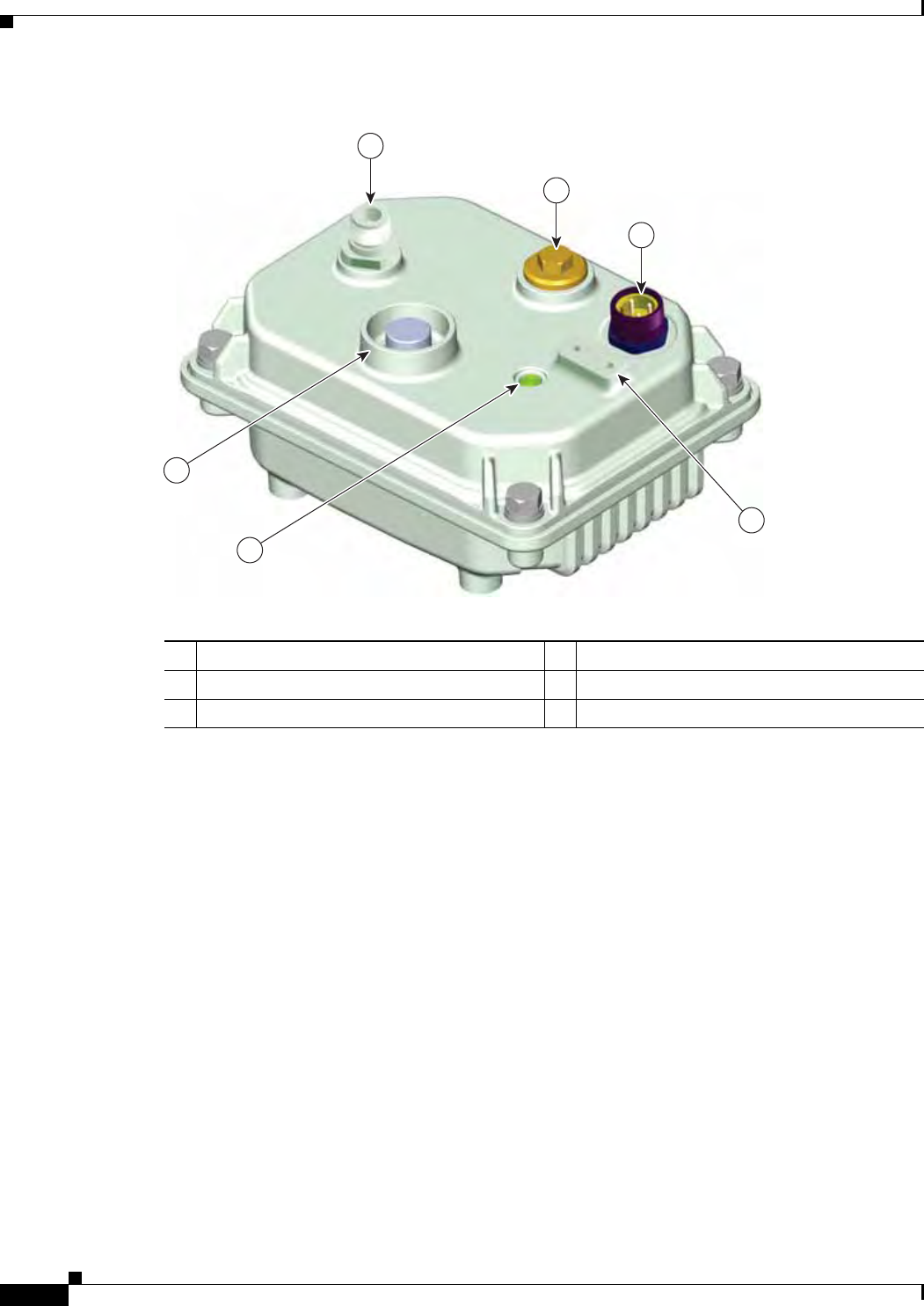
Bottom Panel—WPAN Range Extender
This section describes the WPAN Range Extender bottom panel components shown in Figure 1-4:
• Antenna Connector, page 1-10
• Hard Points, page 1-10
• Console Port, page 1-10
• Protective Vent Port, page 1-11
• Ground Connection, page 1-11
• Power Connector, page 1-11
• System LED, page 1-11
29/OCT/2014 REVIEW DRAFT — CISCO CONFIDENTIAL
1-8
Cisco IR500 Series WPAN Gateway and Range Extender Installation and Configuration Guide
Chapter 1 Overview
Assembly Details
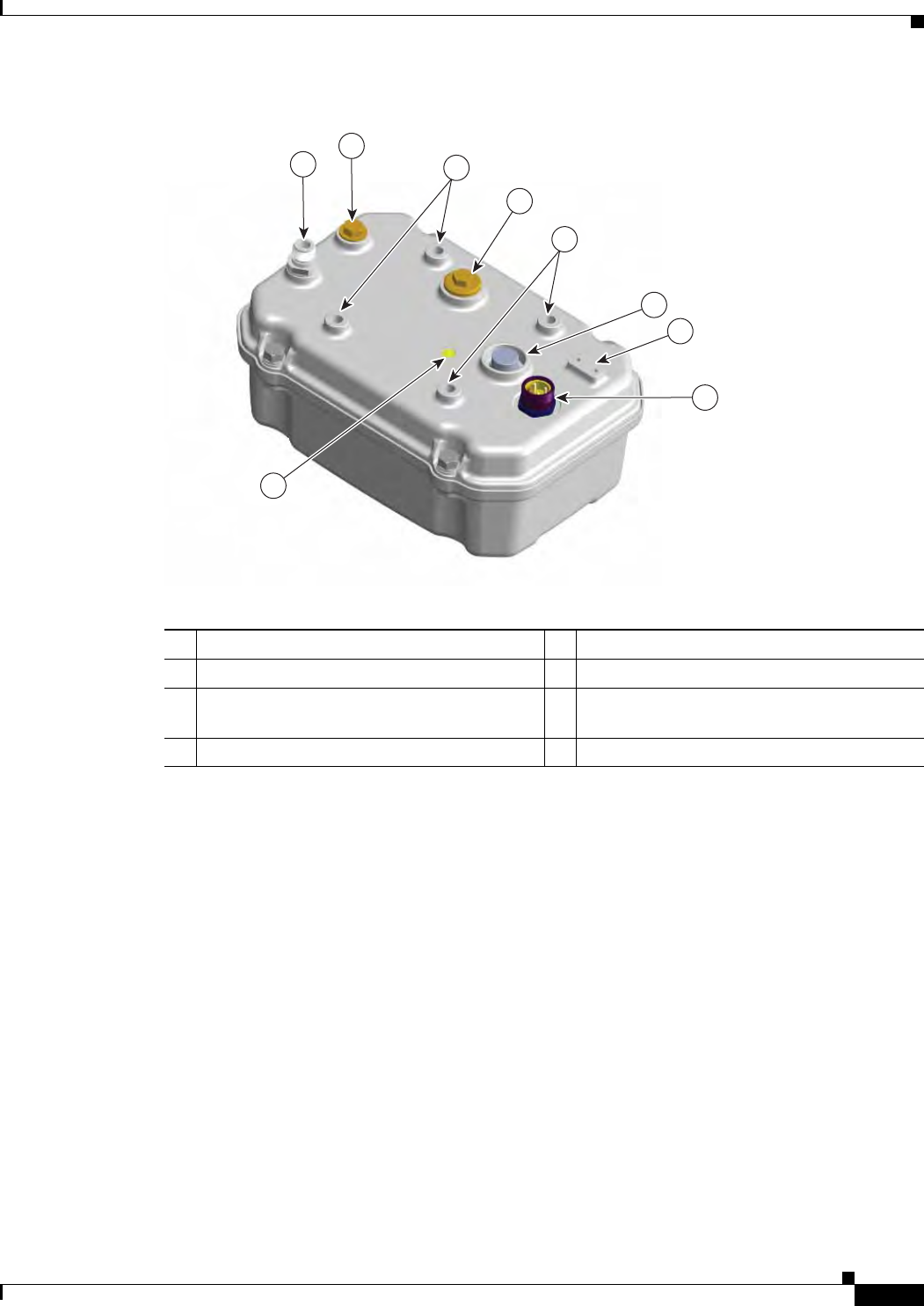
Figure 1-4 Bottom Panel of Basic Range Extender IR529-WP-915S/K9 Model
1
2
3
4
5
6
391364
1Antenna connector—N-type (female) 4Ground connection
2Console port 5System LED
3Power1
1. AC power.
connector 6Protective vent port
29/OCT/2014 REVIEW DRAFT — CISCO CONFIDENTIAL
1-9
Cisco IR500 Series WPAN Gateway and Range Extender Installation and Configuration Guide
Chapter 1 Overview Assembly Details
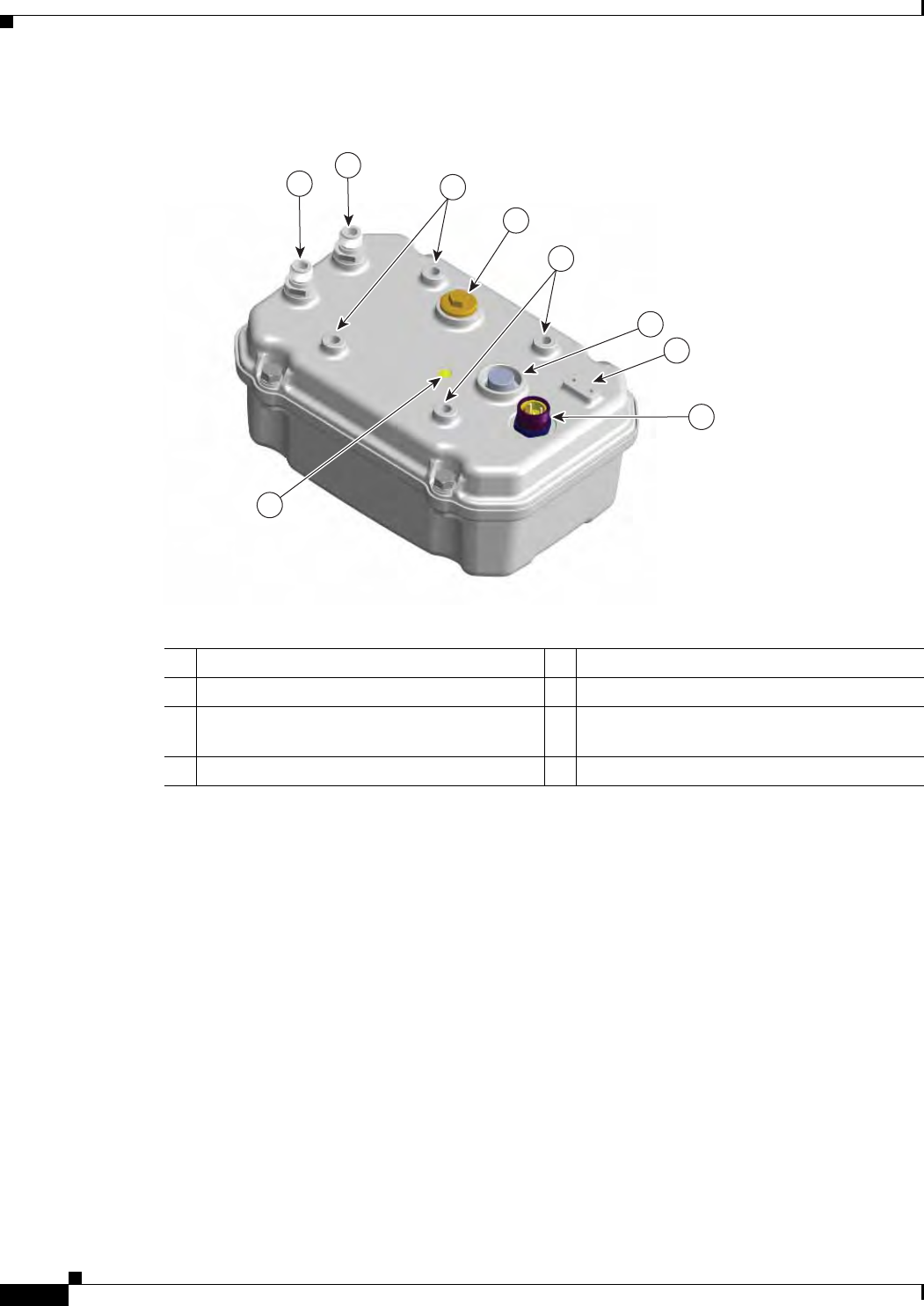
Figure 1-5 Bottom Panel of Advanced Range Extender IR529-UBWP-915S/K9 Model
12
390983
3
4
3
5
6
7
8
1Antenna connector—N-type (female) 5Protective vent port
2Unused port 6Ground connection
3Hard points M8 x 1.25 mm, 8 mm deep
(5/16-18 in., 5/16 in. deep) 7Power1
1. AC power.
connector
4Console port 8System LED
29/OCT/2014 REVIEW DRAFT — CISCO CONFIDENTIAL
1-10
Cisco IR500 Series WPAN Gateway and Range Extender Installation and Configuration Guide
Chapter 1 Overview
Assembly Details
Figure 1-6 Bottom Panel of Advanced Range Extender IR529-UBWP-915D/K9 and
IR529-UWP-915D/K9 Models
12
391360
3
4
3
5
6
7
8
1Antenna connector 1—N-type (female) 5Protective vent port
2Antenna connector 2—N-type (female) 6Ground connection
3Hard points M8 x 1.25 mm, 8 mm deep
(5/16-18 in., 5/16 in. deep) 7Power1
1. AC power.
connector
4Console port 8System LED
Antenna Connector
The antenna connector is a type N female coaxial connector.
Hard Points
The hard points are used for alternate mounting or as attach points for additional equipment.
Console Port
You can connect the WPAN range extender to a PC or laptop through the RJ-45 console port. The RJ-45
console port uses the Cisco Console Port RJ45-to-DB9 cable (Cisco part number 72-3383-01).
The console port is covered with a cable port seal—this is a liquid tight cover for protecting the WPAN
range extender from environmental elements.
For information about connecting to the console port, see the “Connecting to the WPAN Range Extender
Console Port” section on page 5-13.
29/OCT/2014 REVIEW DRAFT — CISCO CONFIDENTIAL
1-11
Cisco IR500 Series WPAN Gateway and Range Extender Installation and Configuration Guide
Chapter 1 Overview Assembly Details
Protective Vent Port
The protective vent port relieves pressure buildup inside the extender chassis that can be caused by
changing temperatures in the installation environment. This prevents pressure from building up and
damaging enclosure seals and the potential exposure of sensitive components to water. The vent also
protects the extender interior from dust, dirt, water, and other environmental elements.
Ground Connection
The ground connection is used to ground the WPAN extender. A provided wired grounding lug is
attached to the ground connection using screws. The other end of the ground wire is connected to an earth
ground, such as a grounding rod or an appropriate grounding point on a pole that is grounded.
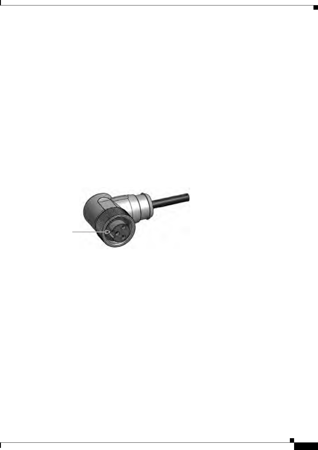
Power Connector
The power connector connects to the Cisco AC power cable shipped with the unit. Figure 1-7 shows the
3 pin AC power connector.
Figure 1-7 WPAN Range Extender AC Power Connector
300595
Notch
System LED
The system LED provide status information on the WPAN range extender activity and performance.
Top Panel—WPAN Range Extender
This section describes the WPAN range extender top panel components shown in Figure 1-7.
29/OCT/2014 REVIEW DRAFT — CISCO CONFIDENTIAL
1-12
Cisco IR500 Series WPAN Gateway and Range Extender Installation and Configuration Guide
Chapter 1 Overview
LEDs
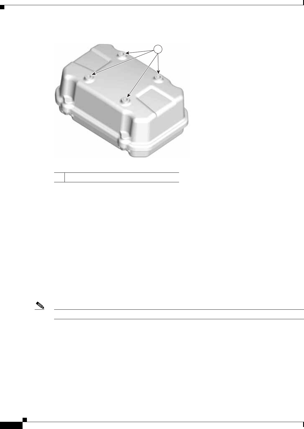
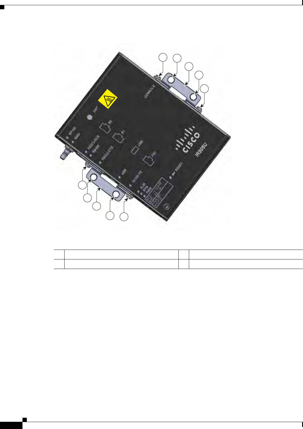
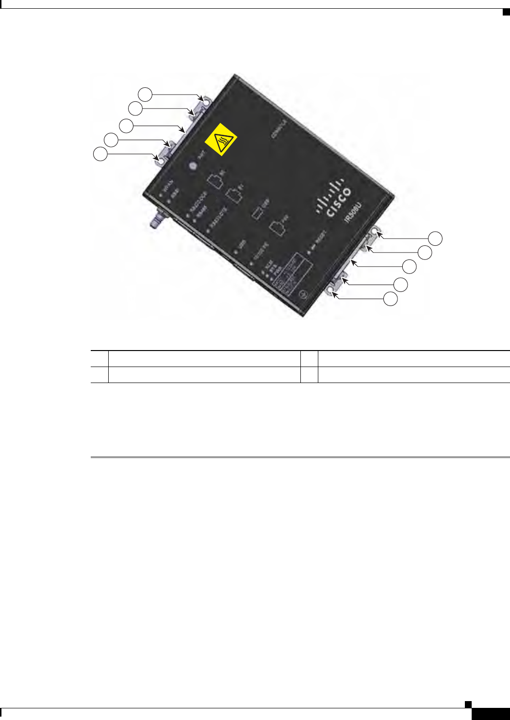
Figure 1-8 Top Panel of Basic and Advanced Range Extender
1
390984
1Mounting holes
The mounting holes are for attaching the range extender to the bracket supplied for mounting the device
on a pole or wall.
LEDs
• WPAN Gateway LEDs, page 1-12
• WPAN Range Extender LEDs, page 1-16
WPAN Gateway LEDs
You can use the LEDs to monitor the gateway status, activity, and performance. Figure 1-9 shows the
front panel LEDs.
Note Each front panel LED has an equivalent matching LED on the top panel (See Figure 1-1).
29/OCT/2014 REVIEW DRAFT — CISCO CONFIDENTIAL
1-13
Cisco IR500 Series WPAN Gateway and Range Extender Installation and Configuration Guide
Chapter 1 Overview LEDs
Figure 1-9 WPAN Gateway Front Panel LEDS
2345
89
10
1
391200
67
1WPAN LED 6USB LED
2RSSI (Received Signal Strength Indication)
LED 710/100 FE LED
3RS232-DCE LED 8Alarm (ALM) LED
4RS485 LED 9System (SYS) LED
5RS232-DTE LED 10 Power (PWR) LED
WPAN LED
The WPAN LED shows the status of the WPAN interface. Table 1-5 lists the WPAN LED colors and their
meanings.
Table 1-5 WPAN LED Status Descriptions
Color Description
Yellow Green
Off Off WPAN port is disabled.
Slow blink Off Searching for network.
Fast blink Off Network Access Control (obtaining link-layer keys).
Slow blink Slow blink Joining network.
Fast blink Fast blink Configuring default route
Off Slow blink DHCPv6

29/OCT/2014 REVIEW DRAFT — CISCO CONFIDENTIAL
1-14
Cisco IR500 Series WPAN Gateway and Range Extender Installation and Configuration Guide
Chapter 1 Overview
LEDs
RSSI LED
The RSSI LED shows the WPAN received signal strength at the WPAN interface. Table 1-6 lists the
RSSI LED colors and their meanings.
Table 1-6 RSSI LED Status Description
Color Description
Yellow Green
Blinking Off Link state to IEEE 802.1x Relay: RSSI below threshold.
Off Blinking Link state to IEEE 802.1x Relay: RSSI above threshold.
On Off RSSI below threshold and/or link ETX above threshold.
Off On RSSI above threshold and link ETX below threshold.
RS232-DCE LED
The RS232-DCE LED shows the status of the RS232 serial communication on the port. Table 1-7 lists
the RS232-DCE LED colors and their meanings.
Table 1-7 RS232-DCE LED Status Description
Color Description
Off RS232 is not selected as the serial communication standard—RS485 is
selected, or the port is turned off completely.
Green RS232 is selected as the serial communication standard and the port is
active.
RS485 LED
The RS485 LED shows the status of the RS485 serial communication on the port. Table 1-7 lists the
RS485 LED colors and their meanings.
Table 1-8 RS485 LED Status Description
Color Description
Off RS485 is not selected as the serial communication standard—RS232 is
selected, or the port is turned off completely.
Green RS485 is selected as the serial communication standard and the port is
active.
Off Fast blink Registering with NMS
Flash On Yellow flash indicates transmission activity
Table 1-5 WPAN LED Status Descriptions (continued)
Color Description
Yellow Green

29/OCT/2014 REVIEW DRAFT — CISCO CONFIDENTIAL
1-15
Cisco IR500 Series WPAN Gateway and Range Extender Installation and Configuration Guide
Chapter 1 Overview LEDs
USB LED
The USB Led shows the status of the USB port. Table 1-9 lists the USB LED Colors and their meanings.
Table 1-9 USB LED Status Description
Color Description
Off USB is not selected as the active DA2 Port (Which means that either the
RS232 is selected as the active DA2 Port or the DA2 port is turned off
completely)
Solid yellow USB is selected as the DA2 Port and is active, but does not detect any
USB device plugged in yet.
Solid green USB port is active and has detected a USB device plugged in to its USB
Port
RS232-DTE LED
The RS232-DTE LED shows the status of the RS232-DTE port. Table 1-10 lists the USB LED Colors
and their meanings.
Table 1-10 RS232-DTE LED Status Description
Color Description
Off RS232-DTE is not selected as the active DA2 Port (Which means that
either the USB is selected as the active DA2 Port or the DA2 port is turned
off completely).
Solid green RS232-DTE is selected as the DA2 Port and is active.
10/100 FE LED
The 10/100 FE LED shows the connectivity status of the 10/100 FE port. Table 1-11 lists the 10/100 FE
LED colors and their meanings.
Table 1-11 10/100 FE LED Status Description
Color Description
Off 10/100 FE port is inactive—the port is powered off or nothing is
connected to it.
Green 10/100 FE port is active—a link is established with a connected device,
and communication is established and a speed is negotiated.
Blinking yellow Traffic activity detected—data communication with a connected device
is in progress.
Power LED
The Power LED shows the power status of the WPAN gateway. Table 1-12 lists the power LED colors
and their meanings.

Table 1-12 Power LED Status Description
Color Description
Off Power is not present on the circuit, or the system is not powered up.
Yellow Power is present on the external circuit, power is absent on an internal
circuit—system is not operating normally.
Green Power is present on external and internal circuits, system is operating
normally
29/OCT/2014 REVIEW DRAFT — CISCO CONFIDENTIAL
1-16
Cisco IR500 Series WPAN Gateway and Range Extender Installation and Configuration Guide
Chapter 1 Overview
LEDs
System LED
The System LED indicates the system status. Table 1-14 lists the system LED colors and their meanings.
Table 1-13 System LED Status Description
Color Description
Blinking Yellow System is booting up
Blinking Green System is active
Alarm LED
The Alarm LED indicates the alarm status. Table 1-14 lists the alarm LED colors and their meanings.
Table 1-14 Alarm LED Status Description
Color Status
Blinking Red Bootload is in progress.
Off No alarm detected.
Red Alarm detected.
WPAN Range Extender LEDs
The WPAN Range Extender has one LED—a System LED.
29/OCT/2014 REVIEW DRAFT — CISCO CONFIDENTIAL
1-17
Cisco IR500 Series WPAN Gateway and Range Extender Installation and Configuration Guide
Chapter 1 Overview Management Options
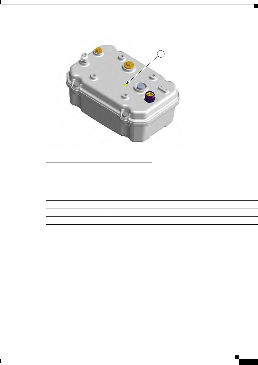
Figure 1-10 WPAN Range Extender Status LED
1
390982
1System LED
The System LED indicates the system status. lists the system LED colors and their meanings.
Table 1-15 System LED Status Description
Color Description
Blinking Yellow System is booting up
Blinking Green System is active
Management Options
• Connected Grid Network Management System, page 1-17
• CSMP Client, page 1-18
Connected Grid Network Management System
The Cisco Connected Grid Network Management System (CG-NMS) manages the WPAN gateway and
WPAN range extender devices. CG-NMS provides:
• Backend network configuration
• Device monitoring
• Event notification services
• Network firmware upgrades

29/OCT/2014 REVIEW DRAFT — CISCO CONFIDENTIAL
1-18
Cisco IR500 Series WPAN Gateway and Range Extender Installation and Configuration Guide
Chapter 1 Overview
Management Options
• Power outage/restoration notification
• Meter registration
CG-NMS also retrieves statistics on network traffic from the devices. For more information on CG-NMS
and configuring the devices, see the Cisco Connected Grid Network Management System User Guide on
Cisco.com.
CSMP Client
CSMP Client is a GUI field tool used to manage and monitor the WPAN gateway and WPAN range
extender hardware and networking information.
The field tool provides two functions, "GET" and “POST” to obtain status and performance information
about the devices in real-time. It can be used as a diagnostic tool to check a single device or the whole
mesh network.
The field tool has three connection modes to connect a WPAN gateway or WPAN range extender:
• Serial connection
• IPv6 wireless connectivity
• Point-to-Point Protocol (PPP)
Connected Grid Device Manager
Connected Grid Device Manager (CG-DM) is a GUI field tool used to troubleshoot, configure and to
update firmware images on WPAN Gateway devices.

CHAPTER
29/OCT/2014 REVIEW DRAFT — CISCO CONFIDENTIAL
2-1
Cisco IR500 Series WPAN Gateway and Range Extender Installation and Configuration Guide
2
Installation
This chapter describes how to install your WPAN gateway and WPAN range extender, and connect the
devices to other devices.
Read these topics, and perform the procedures in this order:
• Preparing for Installation, page 2-1
• Unpacking the Components, page 2-6
• Installation Guidelines, page 2-7
• Installing the Devices, page 2-9
• Connecting the Protective Ground and Power, page 2-18
• Wiring the Alarm Circuits, page 2-29
• Connecting to Device Ports, page 2-33
Preparing for Installation
This section provides information about these topics:
• Warnings, page 2-1
• Additional Information for Installation in a Hazardous Environment, page 2-3
• EMC Environmental Conditions for Products Installed in the European Union, page 2-5
Warnings
These warnings are translated into several languages in the Regulatory Compliance and Safety
Information for these WPAN gateway and WPAN range extender devices.
Warning
IMPORTANT SAFETY INSTRUCTIONS
This warning symbol means danger. You are in a situation that could cause bodily injury. Before you
work on any equipment, be aware of the hazards involved with electrical circuitry and be familiar
with standard practices for preventing accidents. Use the statement number provided at the end of
each warning to locate its translation in the translated safety warnings that accompanied this device.
Statement 1071

29/OCT/2014 REVIEW DRAFT — CISCO CONFIDENTIAL
2-2
Cisco IR500 Series WPAN Gateway and Range Extender Installation and Configuration Guide
Chapter 2 Installation
Preparing for Installation
Warning
In order to comply with FCC radio frequency (RF) exposure limits, antennas for this product should be
located a minimum of 7.9 in. (20 cm) or more from the body of all persons.
Statement 332
Warning
Read the installation instructions before connecting the system to the power source.
Statement 1004
Warning
This product relies on the building’s installation for short-circuit (overcurrent) protection. Ensure that
the protective device is rated not greater than: 2A
Statement 1005
Warning
This unit is intended for installation in restricted access areas. A restricted access area can be
accessed only through the use of a special tool, lock and key, or other means of security.
Statement 1017
Warning
This equipment must be grounded. Never defeat the ground conductor or operate the equipment in the
absence of a suitably installed ground conductor. Contact the appropriate electrical inspection
authority or an electrician if you are uncertain that suitable grounding is available.
Statement 1024
Warning
Only trained and qualified personnel should be allowed to install, replace, or service this equipment.
Statement 1030
Warning
Ultimate disposal of this product should be handled according to all national laws and regulations.
Statement 1040
Warning
To prevent the system from overheating, do not operate it in an area that exceeds the maximum
recommended ambient temperature of:
- Basic WPAN Range Extender: 140°F (60°C)
- Advanced WPAN Range Extender / WPAN Gateway: 158°F (70°C)
Statement 1047
Warning
Installation of the equipment must comply with local and national electric codes.
Statement 1074
Warning
Avoid using or servicing any equipment that has outdoor connections during an electrical storm.
There may be a risk of electric shock from lightning.
Statement 1088
Caution Airflow around the WPAN gateway must be unrestricted. The gateway dimensions (height x width x
depth) are 1.125 x 4.0 x 5.0 in. (2.86 x 10.16 x 12.7 cm). To prevent the WPAN gateway from
overheating, there must be the following minimum clearances:

29/OCT/2014 REVIEW DRAFT — CISCO CONFIDENTIAL
2-3
Cisco IR500 Series WPAN Gateway and Range Extender Installation and Configuration Guide
Chapter 2 Installation Preparing for Installation
- Sides: 1.0 in. (25.4 mm)
- Front: 1.0 in. (25.4 mm)
- Rear: 1.0 in. (25.4 mm)
- Top: 1.0 in. (25.4 mm)—the device can be installed in a 1.25” tall slot, but the mounting surface must
have thermal conductive properties equivalent to or better then 302 stainless steel (16.3 W/m-k)
Contact your Cisco Technical Assistance Centre (TAC) if tighter spacings are required.
Additional Information for Installation in a Hazardous Environment
• Hazardous Locations Warnings for WPAN Gateway Only, page 2-3
• North American Hazardous Location Approval for WPAN Gateway, page 2-5
Hazardous Locations Warnings for WPAN Gateway Only
Warning
Exposure to some chemicals could degrade the sealing properties of materials used in the sealed
relay device.
Statement 381
Warning
Failure to securely tighten the captive screws can result in an electrical arc if the connector is
accidentally removed.
Statement 397
Warning
When you connect or disconnect the power and/or alarm connector with power applied, an electrical
arc can occur. This could cause an explosion in hazardous area installations. Be sure that all power
is removed from the switch and any other circuits. Be sure that power cannot be accidentally turned
on or verify that the area is nonhazardous before proceeding.
Statement 1058
Warning
In switch installations in a hazardous location, the DC power source could be located away from the
vicinity of the switch. Before performing any of the following procedures, locate the DC circuit to
ensure that the power is removed and cannot be turned on accidentally, or verify that the area is
nonhazardous before proceeding.
Statement 1059
Warning
This equipment is supplied as "open type" equipment. It must be mounted within an enclosure that is
suitably designed for those specific environmental conditions that will be present and appropriately
designed to prevent personal injury resulting from accessibility to live parts. The interior of the
enclosure must be accessible only by the use of a tool. The enclosure must meet IP 54 or NEMA type
4 minimum enclosure rating standards.
Statement 1063
Warning
Use twisted-pair supply wires suitable for 86°F (30°C) above surrounding ambient temperature
outside the enclosure.
Statement 1067

29/OCT/2014 REVIEW DRAFT — CISCO CONFIDENTIAL
2-4
Cisco IR500 Series WPAN Gateway and Range Extender Installation and Configuration Guide
Chapter 2 Installation
Preparing for Installation
Warning
This equipment is intended for use in a Pollution Degree 2 industrial environment, in overvoltage
Category II applications (as defined in IEC publication 60664-1), and at altitudes up to 2000 meters
without derating.
Statement 1068
Warning
When used in a Class I, Division 2, hazardous location, this equipment must be mounted in a suitable
enclosure with a proper wiring method that complies with the governing electrical codes.
Statement
1069
Warning
Do not connect or disconnect cables to the ports while power is applied to the switch or any device
on the network because an electrical arc can occur. This could cause an explosion in hazardous
location installations. Be sure that power is removed from the switch and cannot be accidentally be
turned on, or verify that the area is nonhazardous before proceeding.
Statement 1070
Warning
Explosion Hazard—Do not connect or disconnect wiring while the field-side power is on; an
electrical arc can occur. This could cause an explosion in hazardous location installations. Be sure
that power is removed or that the area is nonhazardous before proceeding.
Statement 1081
Warning
Explosion Hazard—The area must be known to be nonhazardous before installing, servicing, or
replacing the unit.
Statement 1082
Warning
Explosion Hazard—Substitution of components may impair suitability for Class I, Division 2/Zone 2.
Statement 1083
Caution This equipment is only suitable for use in Class I, Division 2, Groups A, B, C, D, or nonhazardous
locations.
Caution For the WPAN gateway, connect only to an NEC Class 2 power source or limited power source as defined
by IEC 60950-1.

29/OCT/2014 REVIEW DRAFT — CISCO CONFIDENTIAL
2-5
Cisco IR500 Series WPAN Gateway and Range Extender Installation and Configuration Guide
Chapter 2 Installation Preparing for Installation
North American Hazardous Location Approval for WPAN Gateway
English:
Products marked "Class I, Div 2, GP A, B, C, D" are suitable for use in Class I Division 2 Groups A, B,
C, D, Hazardous Locations and nonhazardous locations only. Each product is supplied with markings
on the rating nameplate indicating the hazardous location temperature code. When combining
products within a system, the most adverse temperature code (lowest "T" number) may be used to
help determine the overall temperature code of the system. Combinations of equipment in your
system are subject to investigation by the local Authority Having Jurisdiction at the time of
installation.
French:
Informations sur l'utilisation de cet équipement en environnements dangereux:
Les produits marqués "Class I, Div 2, GP A, B, C, D" ne conviennent qu'à une utilisation en
environnements de Classe I Division 2 Groupes A, B, C, D dangereux et non dangereux. Chaque
produit est livré avec des marquages sur sa plaque d'identification qui indiquent le code de
température pour les environnements dangereux. Lorsque plusieurs produits sont combinés dans un
système, le code de température le plus défavorable (code de température le plus faible) peut être
utilisé pour déterminer le code de température global du système. Les combinaisons d'équipements
dans le système sont sujettes à inspection par les autorités locales qualifiées au moment de
l'installation.
EMC Environmental Conditions for Products Installed in the European Union
This section applies to products to be installed in the European Union.
The equipment is intended to operate under the following environmental conditions with respect to
EMC:
• A separate defined location under the user's control.
• Earthing and bonding shall meet the requirements of ETS 300 253 or CCITT K27.
• AC-power distribution shall be one of the following types, where applicable: TN-S and TN-C as
defined in IEC 364-3.
In addition, if equipment is operated in a domestic environment, interference could occur.
Tools and Hardware Required
• WPAN Gateway Tools and Hardware Required, page 2-5
• WPAN Range Extender Tools and Hardware Required, page 2-6
WPAN Gateway Tools and Hardware Required
The tools and hardware required for installing the WPAN gateway are:
• For power and alarm connections, use UL- and CSA-rated style 1007 or 1569 twisted-pair copper
appliance wiring material (AWM) wire
• Wire-stripping tools for stripping 10- and 18-gauge wires
• Ratcheting torque flathead screwdriver that exerts up to 15 in-lb (1.69 N-m) of pressure.
• A number-2 Phillips screwdriver.

29/OCT/2014 REVIEW DRAFT — CISCO CONFIDENTIAL
2-6
Cisco IR500 Series WPAN Gateway and Range Extender Installation and Configuration Guide
Chapter 2 Installation
Unpacking the Components
WPAN Range Extender Tools and Hardware Required
The tools and hardware required for installing the WPAN range extender are:
• Crimping tool (such as Thomas & Bett part number WT2000, ERG-2001, or equivalent).
• 6-gauge copper ground wire
• Wire-stripping tools for stripping 6-gauge wire
• A number-2 Phillips screwdriver
Unpacking the Components
• WPAN Gateway Package Contents, page 2-6
• Unpacking the WPAN Gateway, page 2-6
• WPAN Range Extender Package Contents, page 2-7
• Unpacking the WPAN Range Extender, page 2-7
WPAN Gateway Package Contents
The typical WPAN gateway package contains the following items:
• WPAN gateway
• Cisco product documentation and translated safety warnings
• 4-way power and alarm connector
• Ground lug (part number 32-204389=)
• Ground screw (part number 48-1163-01=)
• Side wall mounting brackets
• Front and rear wall mounting brackets
Unpacking the WPAN Gateway
When you are unpacking the WPAN gateway, do not remove the foam blocks attached to the antenna
connectors. The foam protects the antenna connectors during installation.
To unpack the WPAN gateway, follow these steps:
Step 1 Open the shipping container and carefully remove the contents.
Step 2 Return all packing materials to the shipping container, and save it.
Step 3 Ensure that all items listed in “Package Contents” section are included in the shipment. If any item is
damaged or missing, notify your sales representative.

29/OCT/2014 REVIEW DRAFT — CISCO CONFIDENTIAL
2-7
Cisco IR500 Series WPAN Gateway and Range Extender Installation and Configuration Guide
Chapter 2 Installation Installation Guidelines
WPAN Range Extender Package Contents
The typical WPAN range extender package contains the following items:
• WPAN range extender
• Cisco product documentation and translated safety warnings
• Power cable (Cisco Part Number: 72-5307-01)
• Ground lug (Panduit PLCD6-10A-L) and screws
Unpacking the WPAN Range Extender
When you are unpacking the WPAN gateway, do not remove the foam blocks attached to the antenna
connectors. The foam protects the antenna connectors during installation.
To unpack the range extender, follow these steps:
Step 1 Open the shipping container and carefully remove the contents.
Step 2 Return all packing materials to the shipping container, and save it.
Step 3 Ensure that all items listed in “Package Contents” section are included in the shipment. If any item is
damaged or missing, notify your sales representative.
Installation Guidelines
Because the WPAN gateway and WPAN range extender are radio devices, they are susceptible to
common causes of interference that can reduce throughput and range. Follow these basic guidelines to
ensure the best possible performance:
• For information on planning and initially configuring your Cisco Mesh network, refer to the Cisco
Wireless Mesh Access Points, Design and Deployment Guide on Cisco.com
• Review the FCC guidelines for installing and operating outdoor wireless LAN devices at:
http://www.cisco.com/en/US/partner/prod/collateral/routers/ps272/data_sheet_c78-647116_ps114
51_Products_Data_Sheet.html
• Perform a site survey before beginning the installation.
• Install the WPAN gateway and WPAN range extender in an area where structures, trees, or hills do
not obstruct radio signals to and from the devices.
• The WPAN gateway and WPAN range extender can be installed at any height, but best throughput
is achieved when all the WPAN gateways and WPAN range extenders are mounted at the same
height. We recommend installing the devices no higher than 40 feet to allow support for wireless
clients on the ground.
Caution Airflow around the WPAN gateway must be unrestricted. The gateway dimensions (height x width x
depth) are 1.125 x 4.0 x 5.0 in. (2.86 x 10.16 x 12.7 cm). To prevent the WPAN gateway from
overheating, there must be the following minimum clearances:
- Sides: 1.0 in. (25.4 mm)
- Front: 1.0 in. (25.4 mm)

29/OCT/2014 REVIEW DRAFT — CISCO CONFIDENTIAL
2-8
Cisco IR500 Series WPAN Gateway and Range Extender Installation and Configuration Guide
Chapter 2 Installation
Installation Guidelines
- Rear: 1.0 in. (25.4 mm)
- Top: 1.0 in. (25.4 mm)—the device can be installed in a 1.25” tall slot, but the mounting surface must
have thermal conductive properties equivalent to or better then 302 stainless steel (16.3 W/m-k)
Contact your Cisco Technical Assistance Centre (TAC) if tighter spacings are required.
Site Surveys
Every network application is a unique installation. Before installing multiple WPAN gateways and
WPAN range extenders, you should perform a site survey to determine the optimum use of networking
components and to maximize range, coverage, and network performance.
Consider the following operating and environmental conditions when performing a site survey:
• Data rates—Sensitivity and range are inversely proportional to data bit rates. The maximum radio
range is achieved at the lowest workable data rate. A decrease in receiver sensitivity occurs as the
radio data increases.
• Antenna type and placement—Proper antenna configuration is a critical factor in maximizing radio
range. As a general rule, range increases in proportion to antenna height. However, do not place the
antenna higher than necessary, because the extra height also increases potential interference from
other unlicensed radio systems and decreases the wireless coverage from the ground.
• Physical environment—Clear or open areas provide better radio range than closed or filled areas.
• Obstructions—Physical obstructions such as buildings, trees, or hills can hinder performance of
wireless devices. Avoid locating the devices in a location where there is an obstruction between the
sending and receiving antennas.
Becoming Familiar with WPAN Gateway and WPAN Range Extender
Installation Options and Components
• WPAN Gateway Installation Options and Components, page 2-8
• WPAN Range Extender Installation Options and Components, page 2-8
WPAN Gateway Installation Options and Components
The WPAN gateway has a ruggedized IP41 enclosure and it can be installed in the following locations:
• Outdoor cabinet installations—the WPAN gateway is mounted on a DIN rail within the cabinet. For
more information, see the “Mounting the WPAN Gateway on a DIN Rail” section on page 2-9.
• Interior wall installations—the WPAN gateway is mounted on a wall using wall mounting brackets.
For more information, see the “Mounting the WPAN Gateway on a Wall” section on page 2-13.
WPAN Range Extender Installation Options and Components
The WPAN range extender (basic or advanced model) is mounted on a pole. For more information, see
the “Mounting the Range Extender on a Pole” section on page 2-15.

29/OCT/2014 REVIEW DRAFT — CISCO CONFIDENTIAL
2-9
Cisco IR500 Series WPAN Gateway and Range Extender Installation and Configuration Guide
Chapter 2 Installation Installing the Devices
Installing the Devices
• Mounting the WPAN Gateway, page 2-9
• Mounting the Range Extender, page 2-15
Mounting the WPAN Gateway
• Mounting the WPAN Gateway on a DIN Rail, page 2-9
• Mounting the WPAN Gateway on a Wall, page 2-13
Mounting the WPAN Gateway on a DIN Rail
• Attaching the DIN Rail Mounting Bracket to the WPAN Gateway, page 2-9
• Attaching the WPAN Gateway to a DIN Rail, page 2-11
Attaching the DIN Rail Mounting Bracket to the WPAN Gateway
The WPAN gateway is attached to a DIN rail spring loaded mounting bracket (part number
700-103853-01) for mounting on a DIN rail.
To attach the DIN rail mounting bracket to the gateway:
Step 1 Decide if the WPAN gateway is to be mounted in a horizontal or vertical orientation.
Step 2 Align the DIN rail mounting bracket with the mounting hoes as shown in Figure 2-1, and screw the
mounting screws and washers into place. The completed assembly is shown in Figure 2-2.
29/OCT/2014 REVIEW DRAFT — CISCO CONFIDENTIAL
2-10
Cisco IR500 Series WPAN Gateway and Range Extender Installation and Configuration Guide
Chapter 2 Installation
Installing the Devices
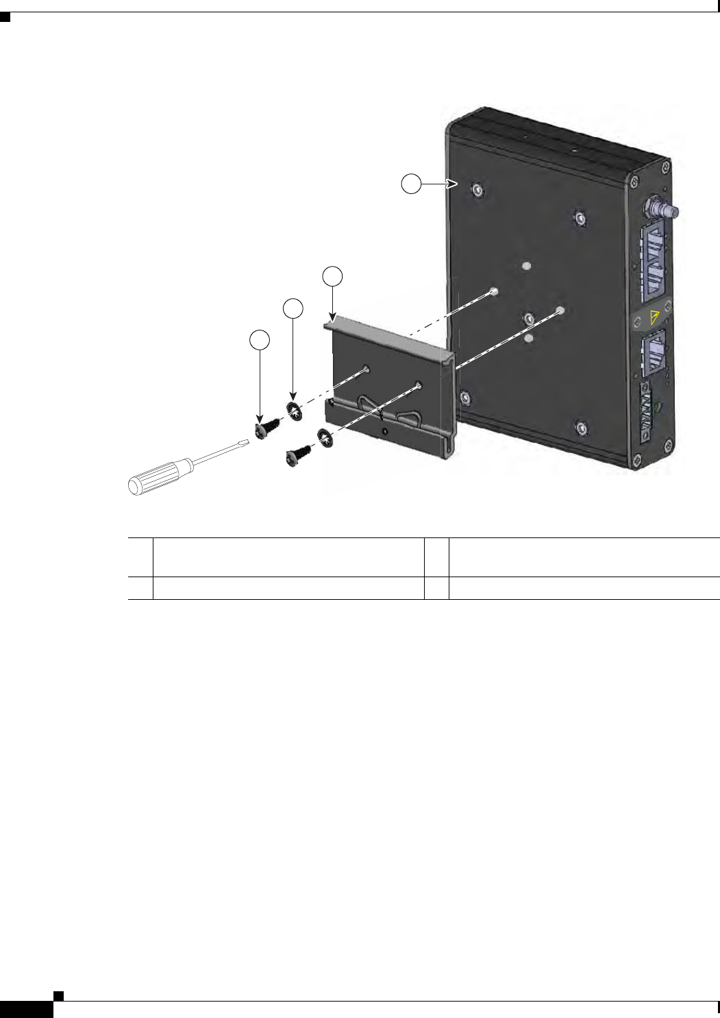
Figure 2-1 Attaching the DIN Rail Mounting Bracket to the WPAN Gateway
4
391283
2
1
3
1DIN rail mounting bracket (part number
700-103853-01) 3Screws
2Toothed lock washer 4WPAN gateway
29/OCT/2014 REVIEW DRAFT — CISCO CONFIDENTIAL
2-11
Cisco IR500 Series WPAN Gateway and Range Extender Installation and Configuration Guide
Chapter 2 Installation Installing the Devices
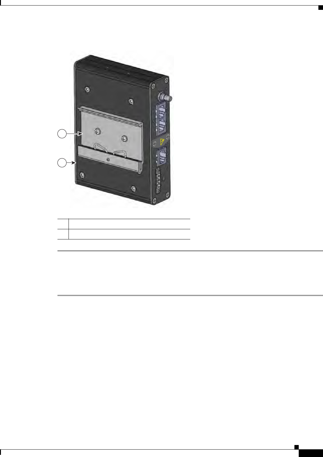
Figure 2-2 Assembled WPAN Gateway and DIN Rail Mounting Bracket
1WPAN gateway
2DIN rail mounting bracket
1
2
391284
Attaching the WPAN Gateway to a DIN Rail
To attach the WPAN Gateway to a DIN Rail:
Step 1 Position the base of the WPAN Gateway (and the attached DIN mounting rail) directly in front of the
DIN rail.
Step 2 Place the spring loaded lower lip of the DIN mounting bracket over the lower edge of the DIN rail as
shown in Figure 2-3, and put pressure on it by pressing it upwards. Maintain the pressure.
29/OCT/2014 REVIEW DRAFT — CISCO CONFIDENTIAL
2-12
Cisco IR500 Series WPAN Gateway and Range Extender Installation and Configuration Guide
Chapter 2 Installation
Installing the Devices
Figure 2-3 Positioning the WPAN Gateway on the DIN Rail
1
3
391285
2
1DIN rail mounting bracket lower lip 3DIN rail mounting bracket upper lip
2DIN rail
Step 3 Place the upper lip of the DIN mounting bracket over the upper edge of the DIN rail. Release the pressure
on the lower lip. The WPAN Gateway will mount onto the DIN rail as shown in Figure 2-4.
29/OCT/2014 REVIEW DRAFT — CISCO CONFIDENTIAL
2-13
Cisco IR500 Series WPAN Gateway and Range Extender Installation and Configuration Guide
Chapter 2 Installation Installing the Devices
Figure 2-4 WPAN Gateway Mounted on the DIN Rail
1
2
391286
1DIN rail
2WPAN gateway
Mounting the WPAN Gateway on a Wall
To mount the WPAN gateway on a wall:
Step 1 Note the mounting orientation of the WPAN gateway based on the use of front and rear wall mounting
brackets (see Figure 2-5) or side wall mounting brackets (see Figure 2-6).
29/OCT/2014 REVIEW DRAFT — CISCO CONFIDENTIAL
2-14
Cisco IR500 Series WPAN Gateway and Range Extender Installation and Configuration Guide
Chapter 2 Installation
Installing the Devices
Figure 2-5 WPAN Gateway with Front and Rear Wall Mounting Brackets
1
2
2
3
3
1
2
2
3
3
391202
1Front and rear wall mounting bracket 3Attachment screws
2Mounting holes
29/OCT/2014 REVIEW DRAFT — CISCO CONFIDENTIAL
2-15
Cisco IR500 Series WPAN Gateway and Range Extender Installation and Configuration Guide
Chapter 2 Installation Installing the Devices
Figure 2-6 WPAN Gateway with Side Wall Mounting Brackets
1
1
3
3
3
3
2
2
2
2
391201
1Side wall mounting bracket 3Mounting holes
2Attachment screws
Step 2 Prepare M8 threaded mounting holes on the wall or the associated mounting plate based on the mounting
dimensions.
Step 3 Place the extender and brackets in the mounting position and screw the M8 mounting screws into
position.
Mounting the Range Extender
• Mounting the Range Extender on a Pole, page 2-15
Mounting the Range Extender on a Pole
This section includes all the procedures required to mount the range extender on any supported pole type.
This section covers:
• Extender Orientation, page 2-16
• Attaching the Mounting Bracket to a Pole, page 2-16
• Attaching the Range Extender to the Mounting Bracket, page 2-16
29/OCT/2014 REVIEW DRAFT — CISCO CONFIDENTIAL
2-16
Cisco IR500 Series WPAN Gateway and Range Extender Installation and Configuration Guide
Chapter 2 Installation
Installing the Devices
Extender Orientation
When mounting the WPAN extender on a pole, ensure that the extender is oriented with the antenna
pointing downwards (see Figure 2-8).
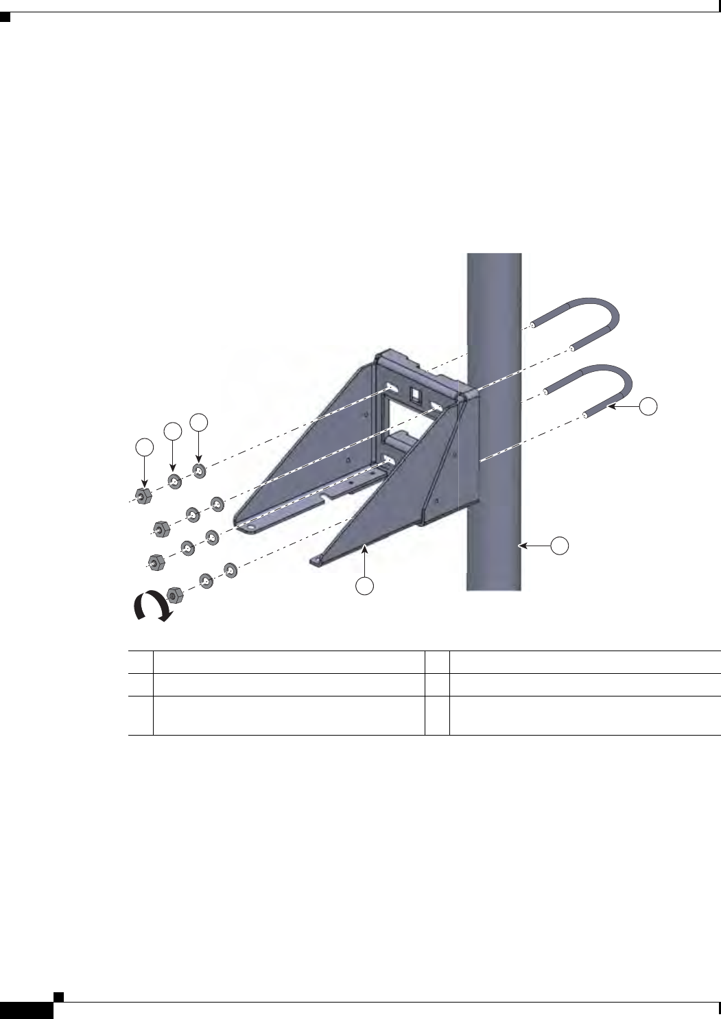
Attaching the Mounting Bracket to a Pole
Attach the mounting bracket to the pole as shown in Fig.
Figure 2-7 Attaching the Range Extender Mounting Bracket to a Pole
1
2
3
4
5
6
391281
1Pole 4Washer
2U bolt (part number 62-2766-01) 5Spring loaded washer
3Pole mounting bracket (part number
700-45850-01) 6Nut
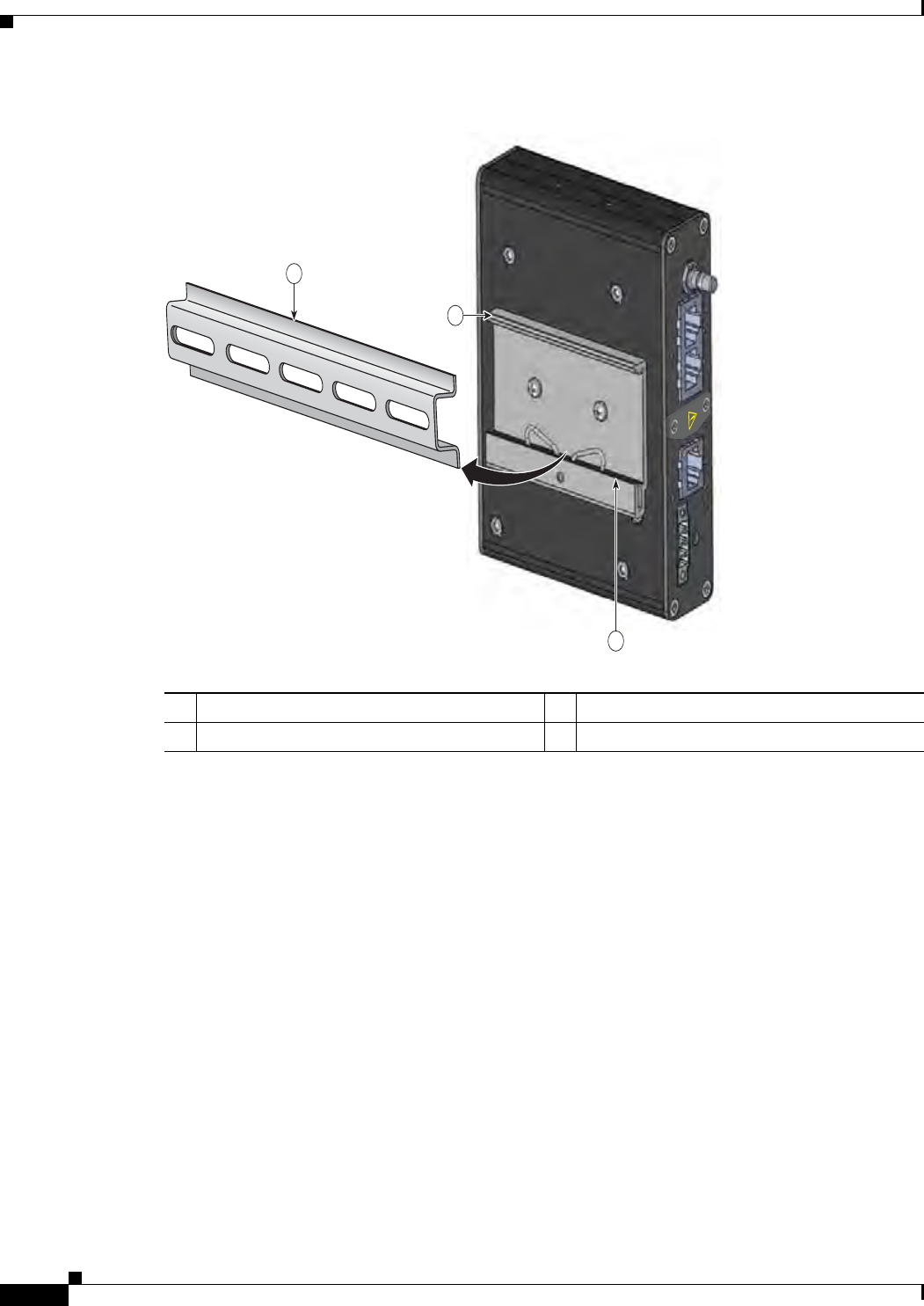
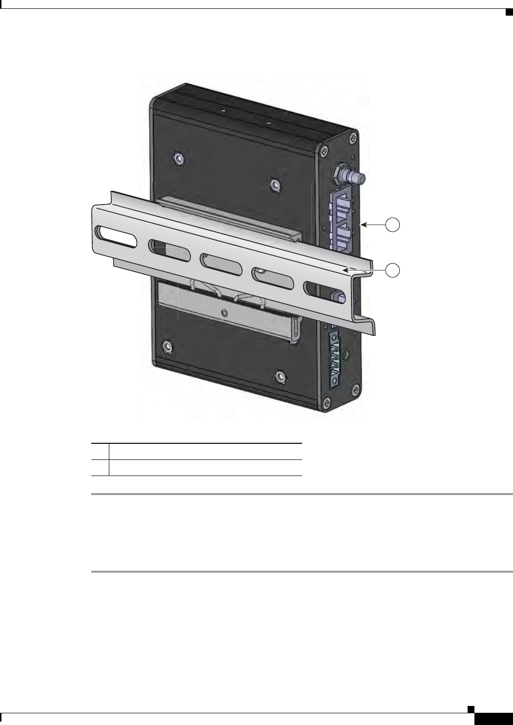
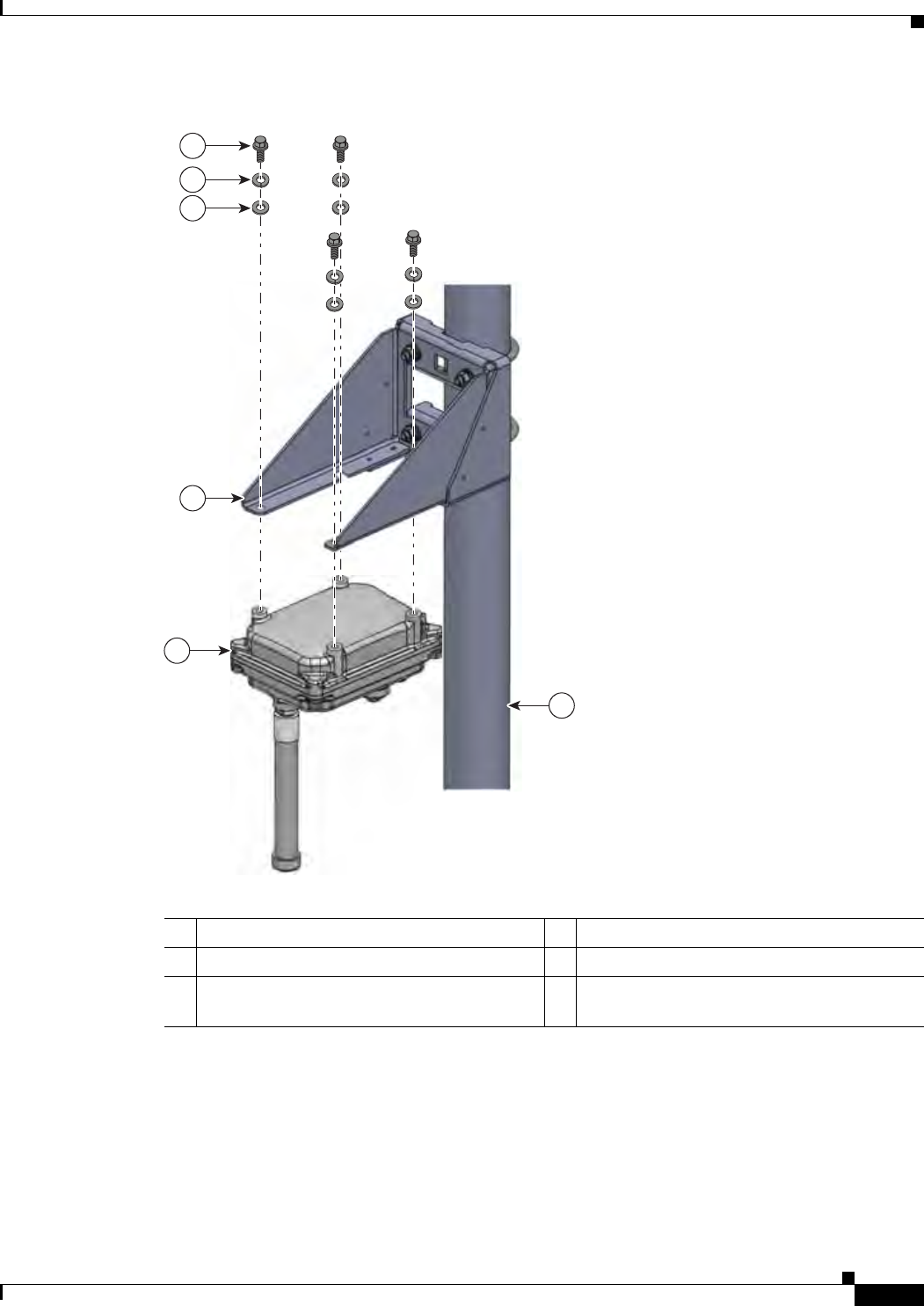
Attaching the Range Extender to the Mounting Bracket
Attach the range extender to the mounting bracket as shown in Figure 2-8.
29/OCT/2014 REVIEW DRAFT — CISCO CONFIDENTIAL
2-17
Cisco IR500 Series WPAN Gateway and Range Extender Installation and Configuration Guide
Chapter 2 Installation Installing the Devices
Figure 2-8 Attaching the Range Extender to the Pole Mounting Bracket
1
2
3
4
5
6
391282
1Pole 4Washer
2WPAN range extender 5Spring loaded washer
3Pole mounting bracket (part number
700-45850-01) 6Screw

29/OCT/2014 REVIEW DRAFT — CISCO CONFIDENTIAL
2-18
Cisco IR500 Series WPAN Gateway and Range Extender Installation and Configuration Guide
Chapter 2 Installation
Connecting the Protective Ground and Power
Connecting the Protective Ground and Power
• Grounding the WPAN Gateway, page 2-18
• Wiring the WPAN Gateway DC Power, page 2-20
• Grounding the WPAN Range Extender, page 2-24
• Wiring the WPAN Range Extender AC Power, page 2-27
Grounding the WPAN Gateway
Make sure to follow any grounding requirements at your site.
Warning
This equipment must be grounded. Never defeat the ground conductor or operate the equipment in the
absence of a suitably installed ground conductor. Contact the appropriate electrical inspection
authority or an electrician if you are uncertain that suitable grounding is available.
Statement 1024
Warning
This equipment is intended to be grounded to comply with emission and immunity requirements.
Ensure that the switch functional ground lug is connected to earth ground during normal use.
Statement 1064
Caution To make sure that the equipment is reliably connected to earth ground, follow the grounding procedure
instructions, and use 14-to-16 AWG wire.
Caution Use at least a 4 mm2 conductor to connect to the external grounding screw.
The ground lug (part number 32-204389=) for the WPAN gateway is supplied.
To ground the WPAN Gateway to earth ground by using the ground screw, follow these steps:
Step 1 Locate the ground screw (part number 48-1163-01=) in the WPAN gateway packaging kit. Store the
ground screw for later use.
Step 2 Use a wire stripping tool to strip the 14-to-16 AWG grounding wire to 0.22 in. (5.56 mm).
Step 3 Insert the ground wire into the ring terminal lug, and using a crimping tool, crimp the terminal to the
wire. See Figure 2-9.
29/OCT/2014 REVIEW DRAFT — CISCO CONFIDENTIAL
2-19
Cisco IR500 Series WPAN Gateway and Range Extender Installation and Configuration Guide
Chapter 2 Installation Connecting the Protective Ground and Power
Figure 2-9 Crimping the Ring Terminal
76666
Step 4 Slide the ground screw through the terminal.
Step 5 Insert the ground screw into the functional ground screw opening on the right side panel.
Step 6 Use a ratcheting torque screwdriver to tighten the ground screw and ring terminal to the WPAN gateway
side panel to 3.5 in-lb (0.4 N-m). The torque should not exceed 3.5 in-lb (0.4 N-m). See Figure 2-10.
Figure 2-10 Installing the Ground-Lug Screw
391917
1
1Ground cable
29/OCT/2014 REVIEW DRAFT — CISCO CONFIDENTIAL
2-20
Cisco IR500 Series WPAN Gateway and Range Extender Installation and Configuration Guide
Chapter 2 Installation
Connecting the Protective Ground and Power
Step 7 Attach the other end of the ground wire to a grounded bare metal surface, such as a ground bus, a
grounded DIN rail, or a grounded bare rack.
Wiring the WPAN Gateway DC Power
Warning
When you connect or disconnect the power and/or alarm connector with power applied, an electrical
arc can occur. This could cause an explosion in hazardous area installations. Be sure that all power
is removed from the switch and any other circuits. Be sure that power cannot be accidentally turned
on or verify that the area is nonhazardous before proceeding.
Statement 1058
Warning
Explosion Hazard—The area must be known to be nonhazardous before installing, servicing, or
replacing the unit.
Statement 1082
Warning
Explosion Hazard—Substitution of components may impair suitability for Class I, Division 2/Zone 2.
Statement 1083
To wire the WPAN Gateway to a DC power source:
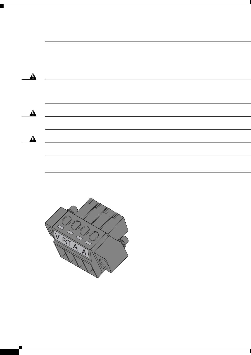
Step 1 Locate the power and alarm connector on the WPAN gateway front panel (see Figure 2-11).
Figure 2-11 WPAN Gateway Power and Alarm Connector
391216
Step 2 Identify the connector positive and return DC power connections. The labels for the power and alarm
connector are shown in Table 2-1.
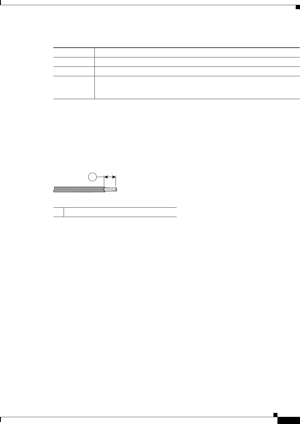
Table 2-1 Power and Alarm Connector Labels
Label Description
VPositive DC power connection
RT Return DC power connection
AEach alarm connection is labeled identically—this means each connection can be an
‘Alarm in’ or ‘Alarm reference’ signal, provided the second alarm connection
provides the other alarm signal.
29/OCT/2014 REVIEW DRAFT — CISCO CONFIDENTIAL
2-21
Cisco IR500 Series WPAN Gateway and Range Extender Installation and Configuration Guide
Chapter 2 Installation Connecting the Protective Ground and Power
Step 3 Measure two strands of twisted-pair copper wire (18-to-20 AWG) long enough to connect to the DC
power source.
Step 4 Using an 18-gauge wire-stripping tool, strip each of the two twisted pair wires coming from each
DC-input power source to 0.25 inch (6.3 mm) ± 0.02 inch (0.5 mm). Do not strip more than 0.27 inch
(6.8 mm) of insulation from the wire. Stripping more than the recommended amount of wire can leave
exposed wire from the power connector after installation.
Figure 2-12 Stripping the Power Connection Wire
97489
1
10.25 in. (6.3 mm) ± 0.02 in. (0.5 mm)
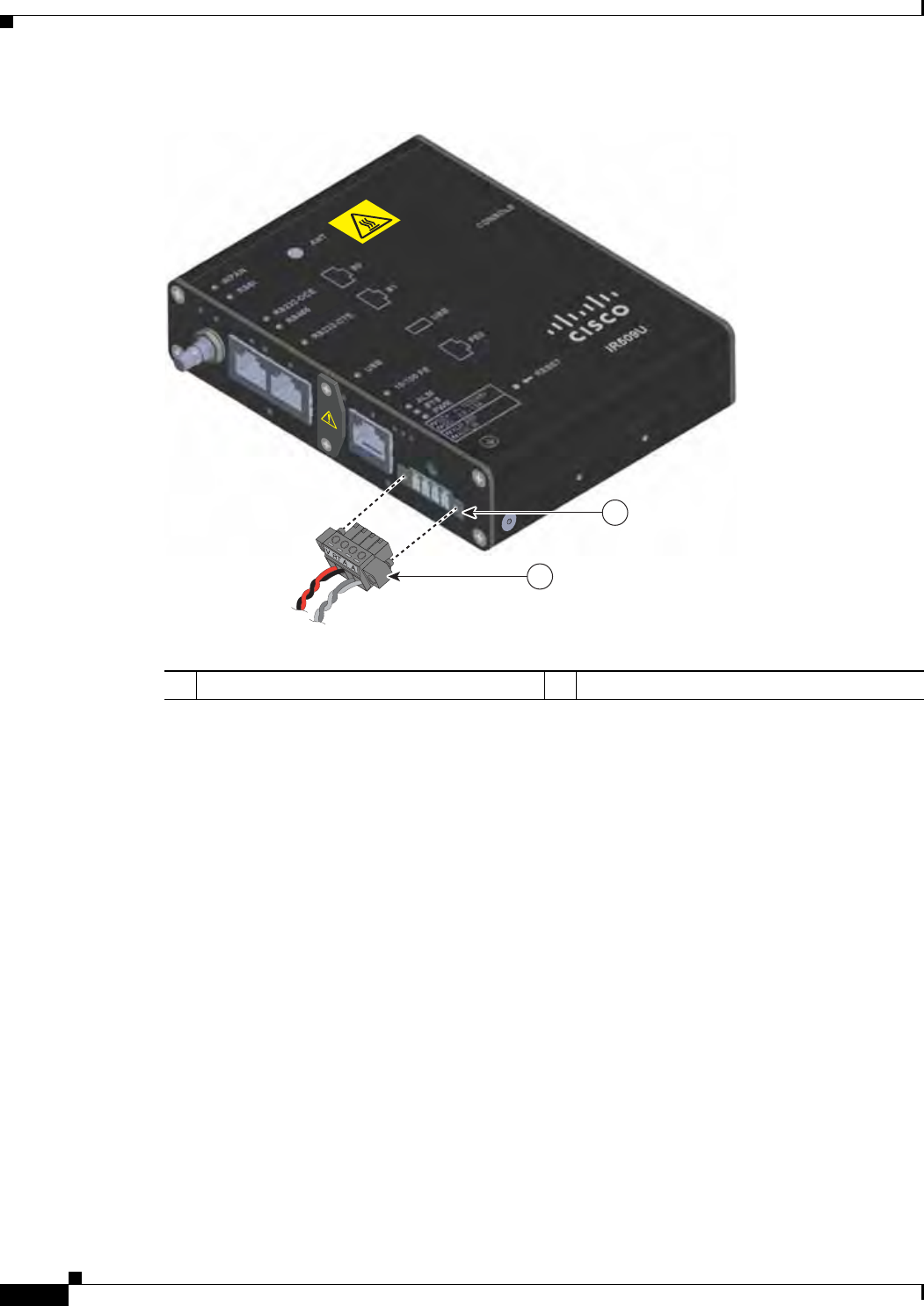
Step 5 Remove the two captive screws that attach the power and alarm connector to the WPAN gateway, and
remove the connector. See Figure 2-13.
29/OCT/2014 REVIEW DRAFT — CISCO CONFIDENTIAL
2-22
Cisco IR500 Series WPAN Gateway and Range Extender Installation and Configuration Guide
Chapter 2 Installation
Connecting the Protective Ground and Power
Figure 2-13 Removing the Power and Alarm Connector from the WPAN Gateway
1
391221
2
1Power and alarm connector Power and alarm connector connection
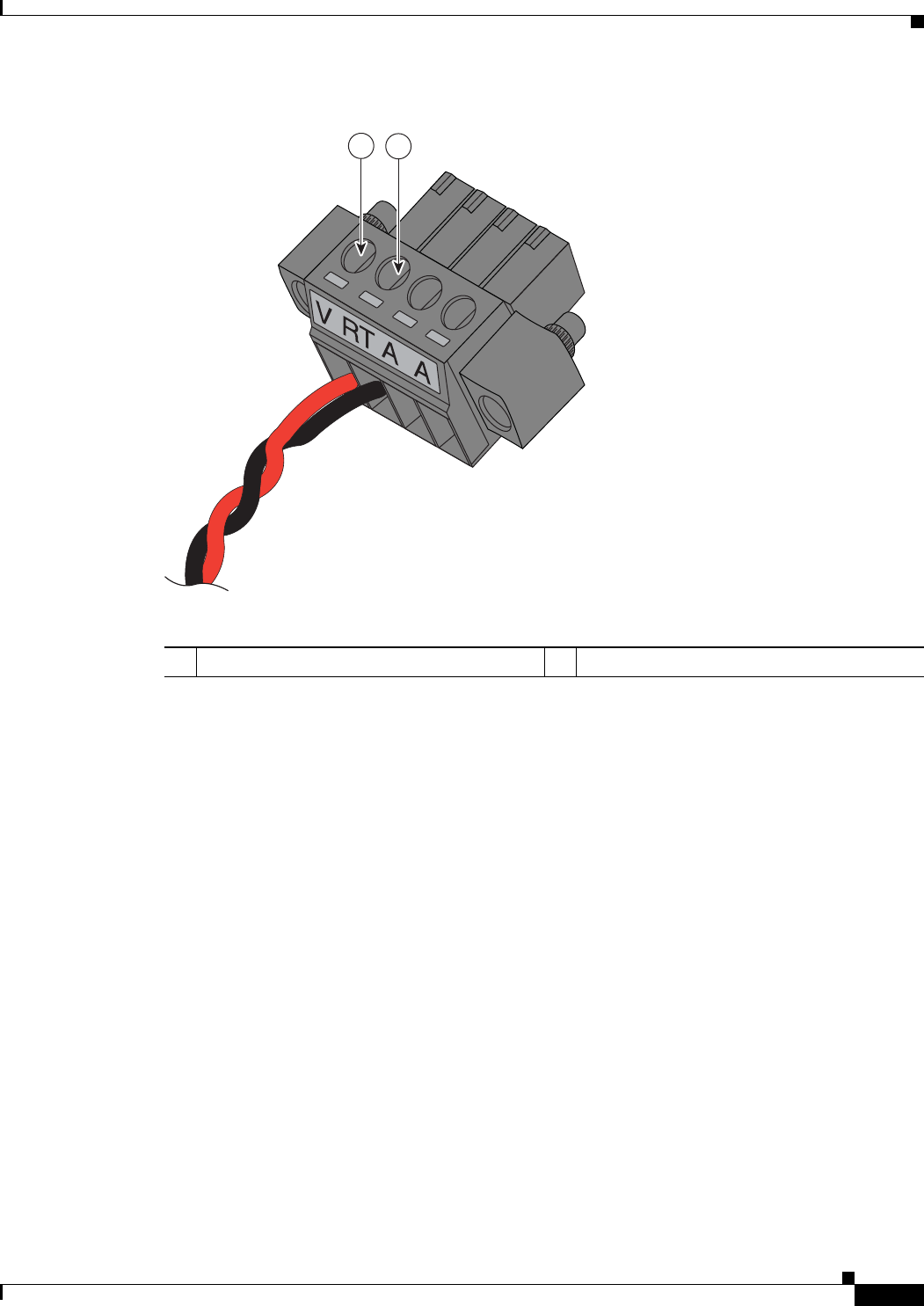
Step 6 On the power and alarm connector, insert the exposed part of the positive wire into the connection
labeled "V" and the exposed part of the return wire into the connection labeled "RT". See Figure 2-14.
Make sure that you cannot see any wire lead. Only wire with insulation should extend from the connector
29/OCT/2014 REVIEW DRAFT — CISCO CONFIDENTIAL
2-23
Cisco IR500 Series WPAN Gateway and Range Extender Installation and Configuration Guide
Chapter 2 Installation Connecting the Protective Ground and Power
Figure 2-14 Inserting the Power and Return Connections in the Power and Alarm Connector
391218
12
1Power source positive connection 2Power source return connection
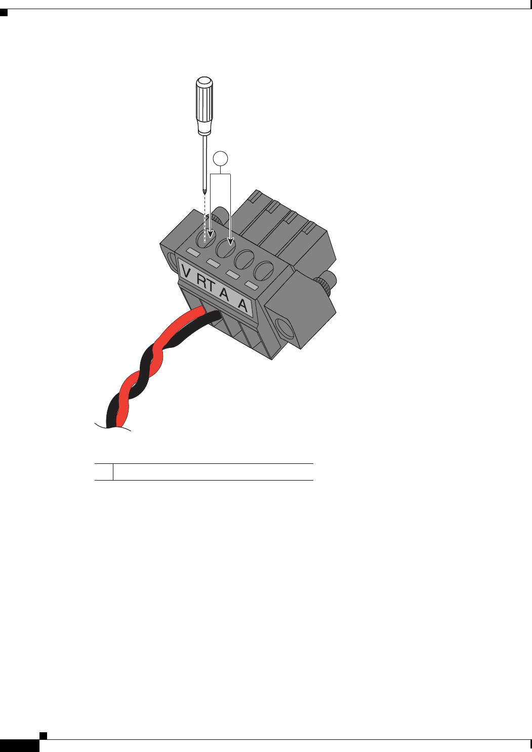
Step 7 Use a ratcheting torque flathead screwdriver to torque the power connector captive screws (above the
installed wire leads) to 2 in-lb (0.23 N-m). See Figure 2-15.
29/OCT/2014 REVIEW DRAFT — CISCO CONFIDENTIAL
2-24
Cisco IR500 Series WPAN Gateway and Range Extender Installation and Configuration Guide
Chapter 2 Installation
Connecting the Protective Ground and Power
Figure 2-15 Torquing the Power and Ground Captive Screws
391217
1
1Power and ground captive screws
Step 8 Connect the other end of the positive wire to the positive terminal on the DC power source, and connect
the other end of the return wire to the return terminal on the DC power source.
The power and alarm connector is attached to the WPAN gateway when the alarm connections on the
connector are completed. For information about wiring the alarm connections and attaching the power
and alarm connector, see the “Attaching the Power and Alarm Connector to the WPAN Gateway” section
on page 2-31.
Grounding the WPAN Range Extender
In all installations, after the WPAN range extender is mounted, you must properly ground the unit before
connecting power cables.
29/OCT/2014 REVIEW DRAFT — CISCO CONFIDENTIAL
2-25
Cisco IR500 Series WPAN Gateway and Range Extender Installation and Configuration Guide
Chapter 2 Installation Connecting the Protective Ground and Power
Warning
This equipment must be grounded. Never defeat the ground conductor or operate the equipment in the
absence of a suitably installed ground conductor. Contact the appropriate electrical inspection
authority or an electrician if you are uncertain that suitable grounding is available.
Statement 1024
Warning
Installation of the equipment must comply with local and national electrical codes.
Statement 1074
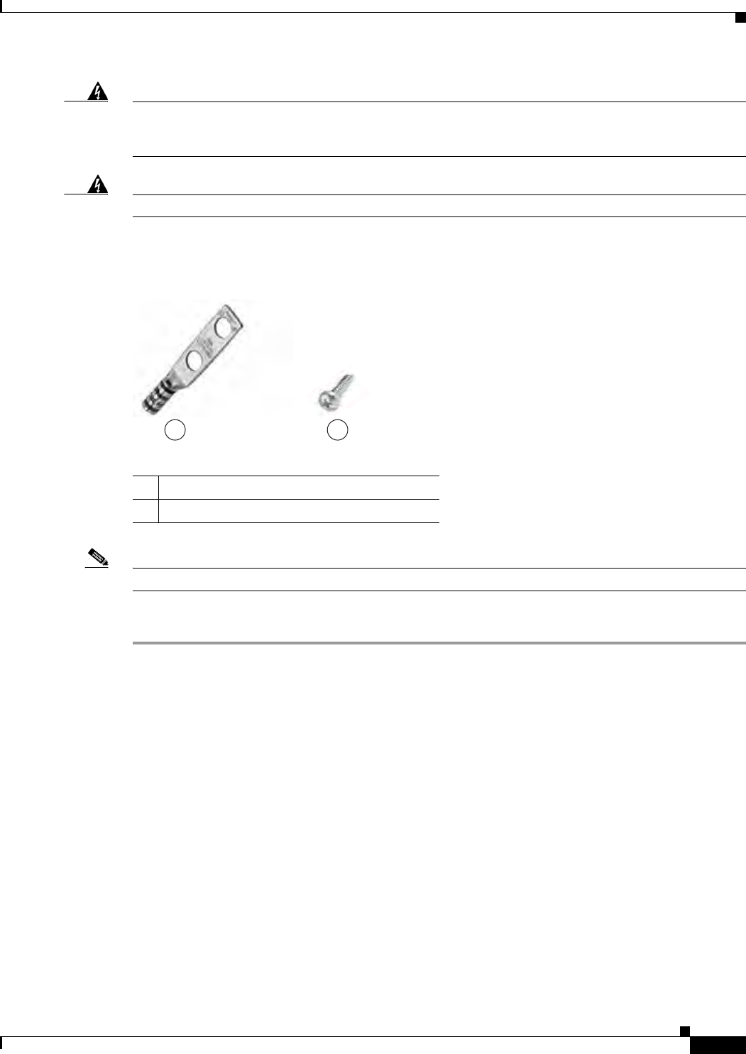
The range extender is shipped with a grounding kit as shown in Figure 2-16.
Figure 2-16 WPAN Range Extender Grounding Kit Contents
300622
1 2
1Grounding lug
2Screws x 2
Note You can perform these steps when the mounting bracket security panel is installed.
To ground the range extender, follow these steps:
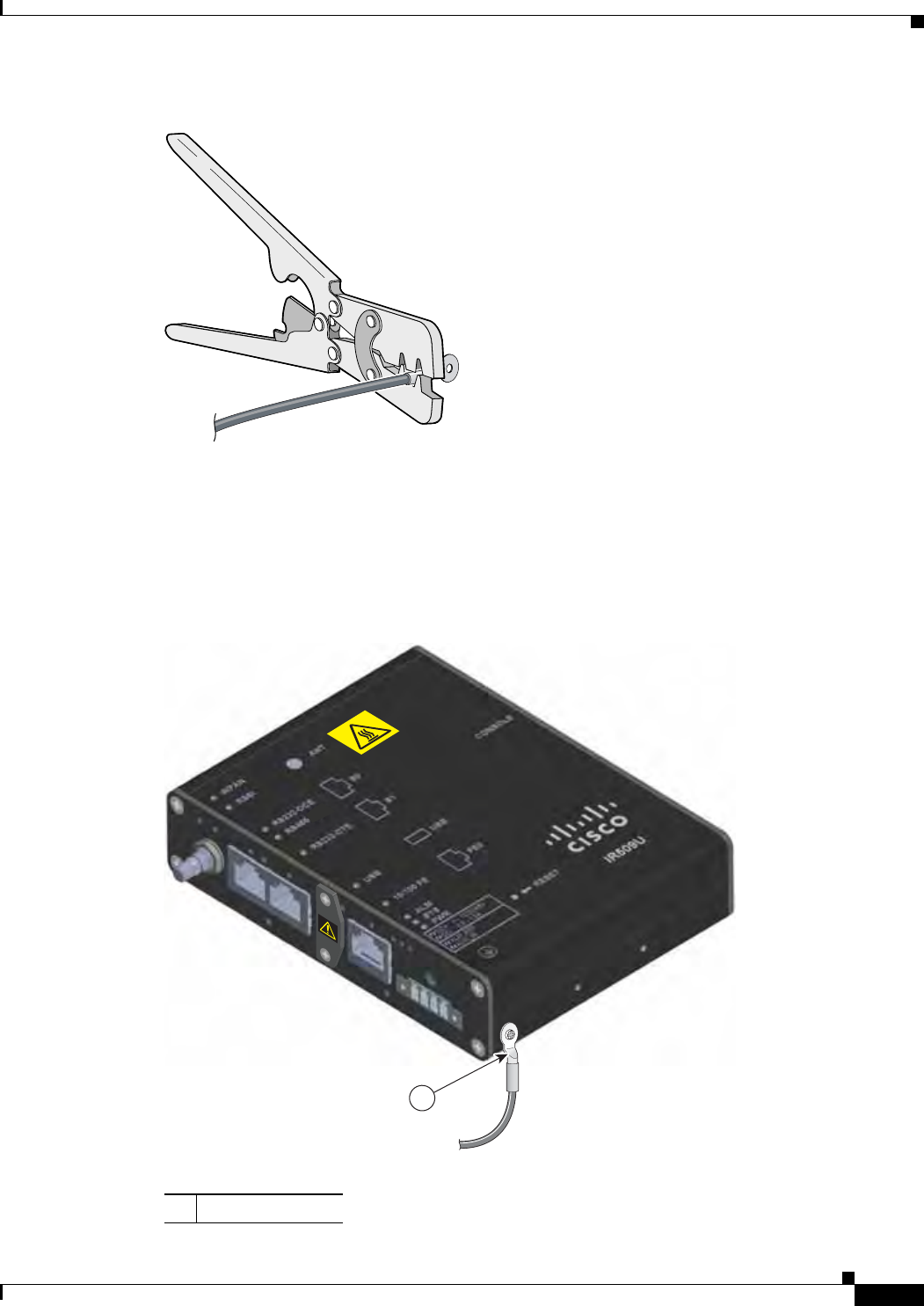
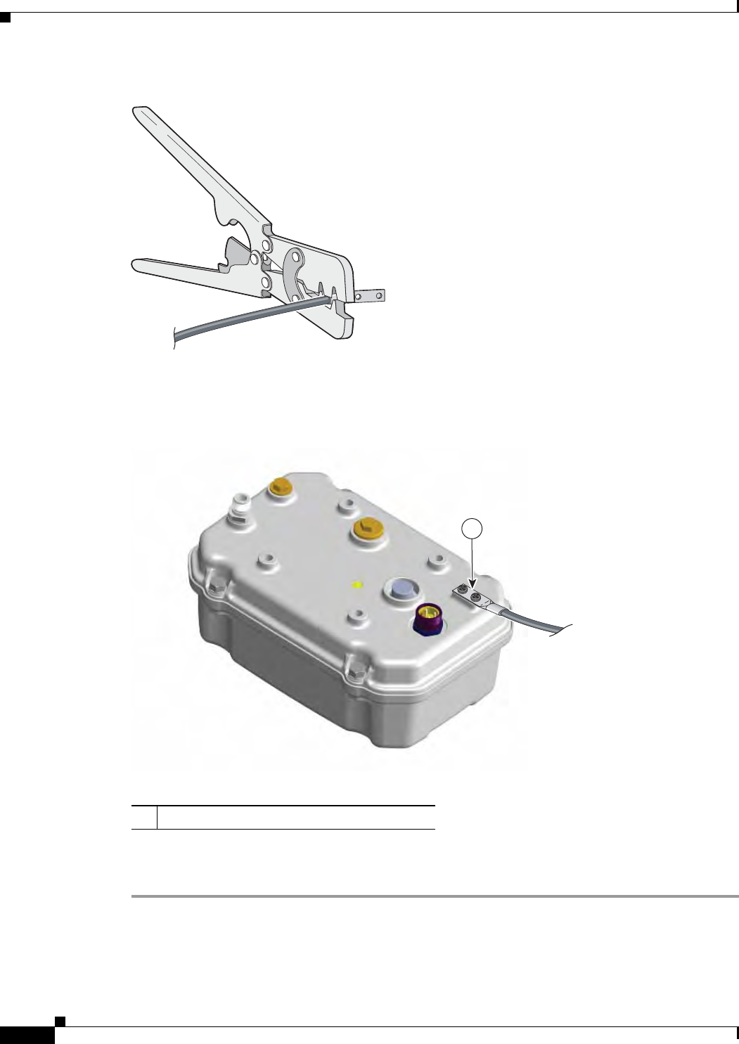
Step 1 Use a crimping tool to crimp the 6-gauge ground wire (included in the grounding kit) to the grounding
lug. See Figure 2-17.
29/OCT/2014 REVIEW DRAFT — CISCO CONFIDENTIAL
2-26
Cisco IR500 Series WPAN Gateway and Range Extender Installation and Configuration Guide
Chapter 2 Installation
Connecting the Protective Ground and Power
Figure 2-17 Crimping the Ground Lug
391287
Step 2 Connect the grounding lug to the range extender ground connection point shown in Figure 2-18 using
the supplied screws. Tighten the screws to 10 to 12 foot-pounds of torque.
Figure 2-18 Installing the Ground Lug
391288
1
1Ground connection
Step 3 If necessary, strip the other end of the ground wire and connect it to a reliable earth ground, such as a
grounding rod or an appropriate grounding point on a pole that is grounded.

29/OCT/2014 REVIEW DRAFT — CISCO CONFIDENTIAL
2-27
Cisco IR500 Series WPAN Gateway and Range Extender Installation and Configuration Guide
Chapter 2 Installation Connecting the Protective Ground and Power
Wiring the WPAN Range Extender AC Power
When wiring the range extender AC power, you must ensure that the following conditions are met:
• AC power can be readily and conveniently removed from the WPAN range extender. The power
should not be removed by disconnecting the AC power connector on the unit. It should be removed
by disabling AC power at the power circuit.
Warning
The AC power supply has double pole/neutral fusing.
Statement 188
Warning
The plug-socket combination must be accessible at all times, because it serves as the main
disconnecting device.
Statement 1019
Caution Before connecting or disconnecting the power cord, you must remove AC power from the power cord
using a suitable service disconnect.
• You must protect AC power plugs and AC receptacles from water and other outdoor elements. You
can use a UL-listed waterproofing enclosure suitable for covering the AC receptacle and AC power
plug that supplies power to the unit, as described in Article 406 of the National Electric Code (NEC).
• When you install the unit outdoors, or in a wet or damp location, the AC branch circuit that powers
the unit should have ground fault protection (GFCI), as required by Article 210 of the NEC.
• If the power cord goes through a metal cover, a bushing should be installed to prevent fraying of the
cord. When using a strain relief bushing, you should follow these recommendations:
–
Use properly sized parts
–
Use bushings that are safety certified
–
Use parts that are suitable for outdoor installation
• Ensure that the user-supplied AC power plug is certified for outdoor use and has a minimum IP67
rating.
The topics in this section include:
• AC Power Cable, page 2-27
• Connecting to AC Power, page 2-28
AC Power Cable
The WPAN range extender supports the Cisco AC power cable that is shipped with the unit. One end of
the cable has the range extender AC power connector; the other end is unfinished and you must provide
and attach an AC power plug, or terminate the cable at your installation site. The AC power plug or
termination method you use depends on the power source, such as a junction box, at your site.
If you attach an AC power plug:
• Use a plug that complies with local and national electrical codes.
• Verify the connection between the cable and plug is weatherproof.
You might have to cut the cable if a specific cable length is needed for your installation.
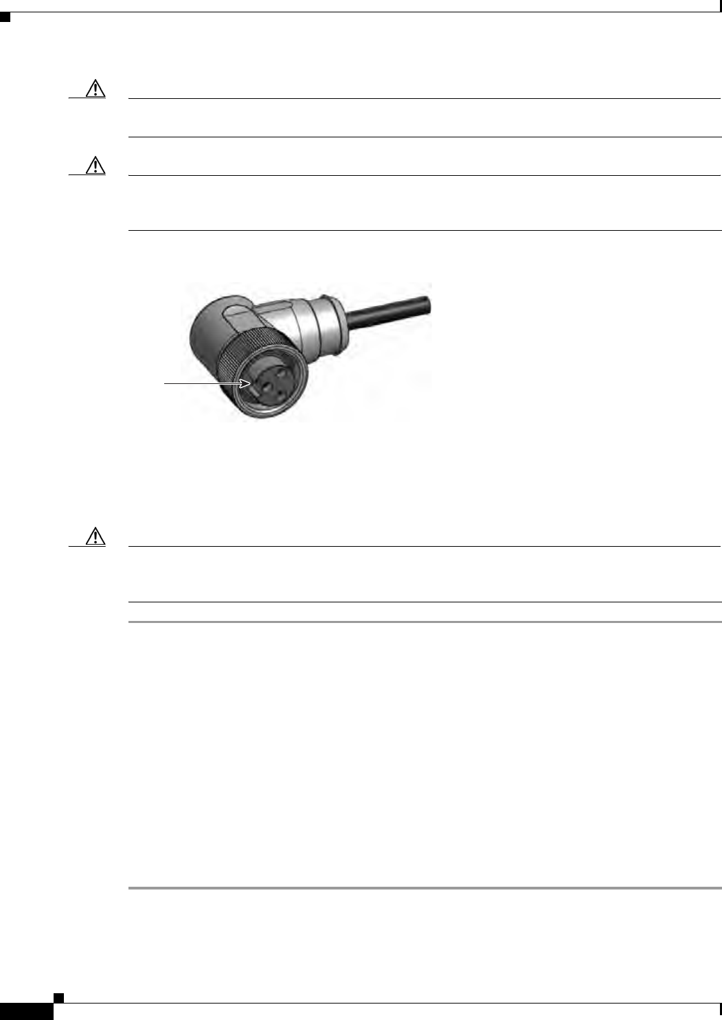
29/OCT/2014 REVIEW DRAFT — CISCO CONFIDENTIAL
2-28
Cisco IR500 Series WPAN Gateway and Range Extender Installation and Configuration Guide
Chapter 2 Installation
Connecting the Protective Ground and Power
Caution Ensure that the power source is OFF before connecting or disconnecting the power cord wires from the
power source.
Caution To attach the appropriate connector the AC power cable, follow the manual or other instructions
provided by the electrical equipment vendor, ensuring that you comply with the electrical codes for your
installation location.
Figure 2-19 WPAN Gateway AC Power Cable (WPAN Gateway Connector End)
300595
Notch
Connecting to AC Power
To connect the WPAN range extender power connector in Figure 2-19 to an AC power source, follow
these steps:
Caution When connecting the AC power connector, always connect the WPAN range extender end of the cable
first. When removing the AC power connector, always disconnect the WPAN range extender end of the
cable last.
Step 1 Verify that the unit is grounded as described in the “Grounding the WPAN Range Extender” section on
page 2-24.
Step 2 Turn off power to the AC power source at the designated circuits.
Step 3 Align the notch in the WPAN range extender power cable connector with the key in the range extender
AC power connector, and push the cable connector into the range extender connector. When the cable
connector is fully seated, rotate the cable connector ring clockwise until it is hand-tightened to a torque
of 6-7 ft-lbs (8.13-9.49 N-m).
Step 4 Confirm the WPAN antennas are connected to the range extender before you apply power to the range
extender.
Step 5 Connect the other end of the AC power cable to the power source, using the instructions that came with
the connecting device.
Step 6 Turn on AC power at the designated circuits. The range extender will power on and boot the software
image.
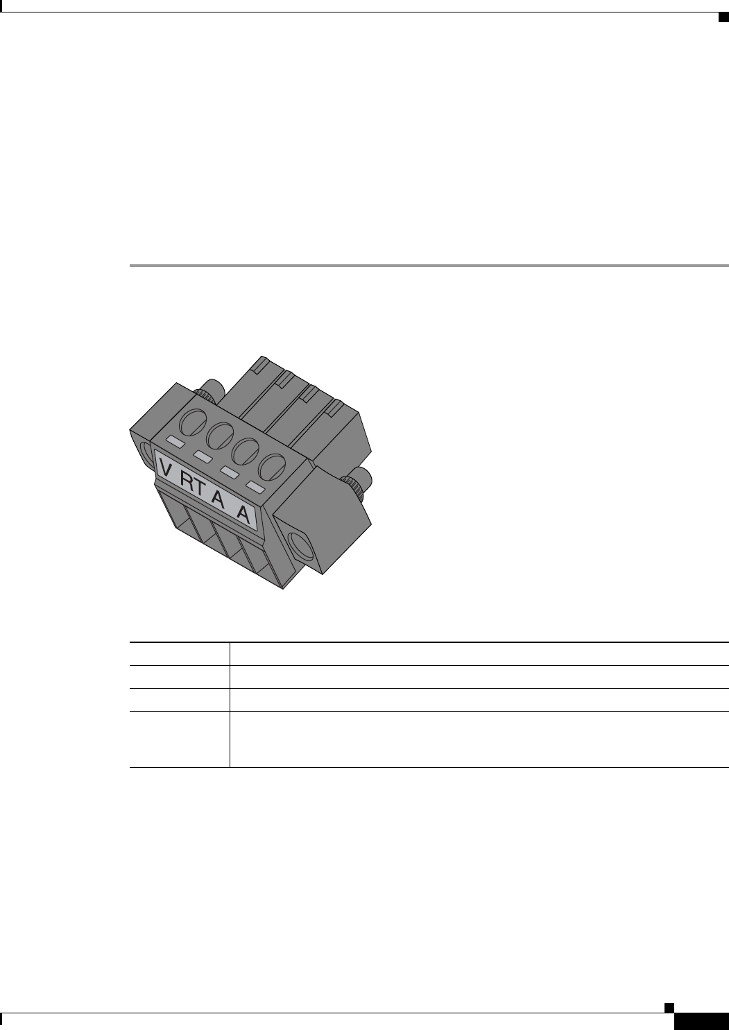
29/OCT/2014 REVIEW DRAFT — CISCO CONFIDENTIAL
2-29
Cisco IR500 Series WPAN Gateway and Range Extender Installation and Configuration Guide
Chapter 2 Installation Wiring the Alarm Circuits
Wiring the Alarm Circuits
• Wiring the WPAN Gateway Alarm, page 2-29
• Attaching the Power and Alarm Connector to the WPAN Gateway, page 2-31
Wiring the WPAN Gateway Alarm
To connect the WPAN gateway alarm connections:
Step 1 Note the alarm connections as described in Figure 2-20. The alarm connection labels are described in
Table 2-2.
Figure 2-20 WPAN Gateway Power and Alarm Connector
391216
Table 2-2 Power and Alarm Connector Labels
Label Description
VPositive DC power connection
RT Return
AEach alarm connection is labeled identically—this means each connection can be an
‘Alarm in’ or ‘Alarm reference’ signal, provided the second alarm connection
provides the other alarm signal.
Step 2 Measure two strands of twisted-pair wire (18-to-20 AWG) long enough to connect to the external alarm
device.
Step 3 Use a wire stripper to remove the casing from both ends of each wire to 0.25 inch (6.3 mm) ± 0.02 inch
(0.5 mm). Do not strip more than 0.27 inch (6.8 mm) of insulation from the wires. Stripping more than
the recommended amount of wire can leave exposed wire from the alarm connector after installation.
Step 4 Insert the exposed wires for the external alarm device into the power and alarm connector connections
as shown in Figure 2-21.
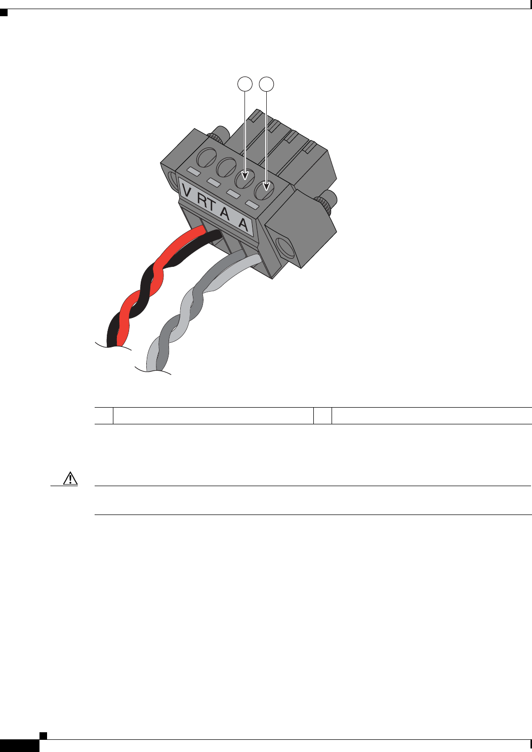
29/OCT/2014 REVIEW DRAFT — CISCO CONFIDENTIAL
2-30
Cisco IR500 Series WPAN Gateway and Range Extender Installation and Configuration Guide
Chapter 2 Installation
Wiring the Alarm Circuits
Figure 2-21 Inserting Wires into the Alarm Connections
391219
12
1Alarm reference 2Alarm in
Step 5 Use a ratcheting torque flathead screwdriver to tighten the alarm connector captive screw (above the
installed wire leads) to 2 in-lb (0.23 N-m). See Figure 2-22.
Caution Do not over-torque the power and alarm connector's captive screws. The torque should not exceed 2 in-lb
(0.23 N-m).
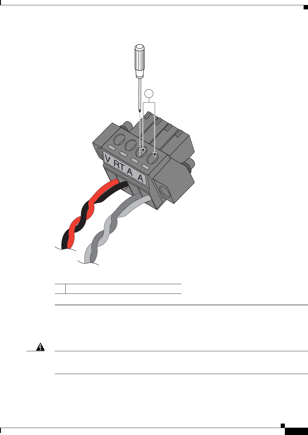
29/OCT/2014 REVIEW DRAFT — CISCO CONFIDENTIAL
2-31
Cisco IR500 Series WPAN Gateway and Range Extender Installation and Configuration Guide
Chapter 2 Installation Wiring the Alarm Circuits
Figure 2-22 Securing the Alarm Connections Captive Screws
391220
1
1Alarm connections captive screws
Attaching the Power and Alarm Connector to the WPAN Gateway
Warning
This product relies on the building’s installation for short-circuit (overcurrent) protection. Ensure that
the protective device is rated not greater than: 2A
Statement 1005
To attach the power and alarm connector to the front panel of WPAN gateway:
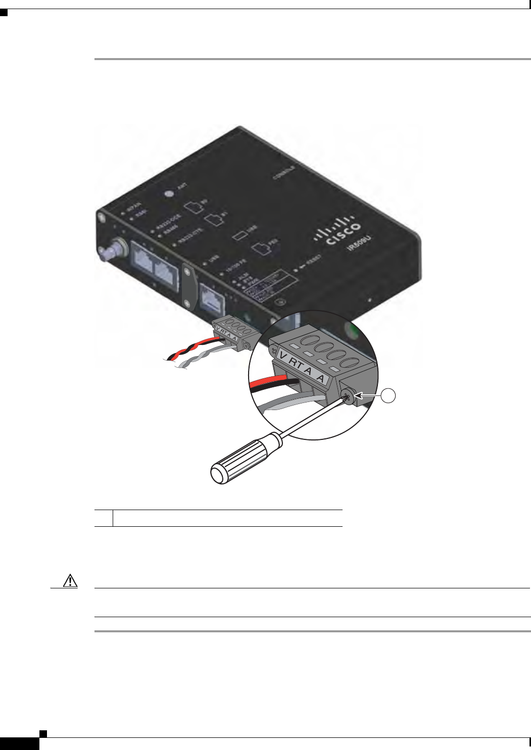
29/OCT/2014 REVIEW DRAFT — CISCO CONFIDENTIAL
2-32
Cisco IR500 Series WPAN Gateway and Range Extender Installation and Configuration Guide
Chapter 2 Installation
Wiring the Alarm Circuits
Step 1 Insert the power and alarm connector into the receptacle on the WPAN gateway front panel. See
Figure 2-23.
Figure 2-23 Connecting the Power and Alarm Connector to the WPAN Gateway
391222
1
1Power and alarm connector captive right side screw
Step 2 Use a ratcheting torque flathead screwdriver to tighten the captive screws on both sides of the power and
alarm connector to 2 in-lb (0.23 N-m).
Caution Do not over-torque the power and alarm connector's captive screws. The torque should not exceed 2 in-lb
(0.23 N-m).
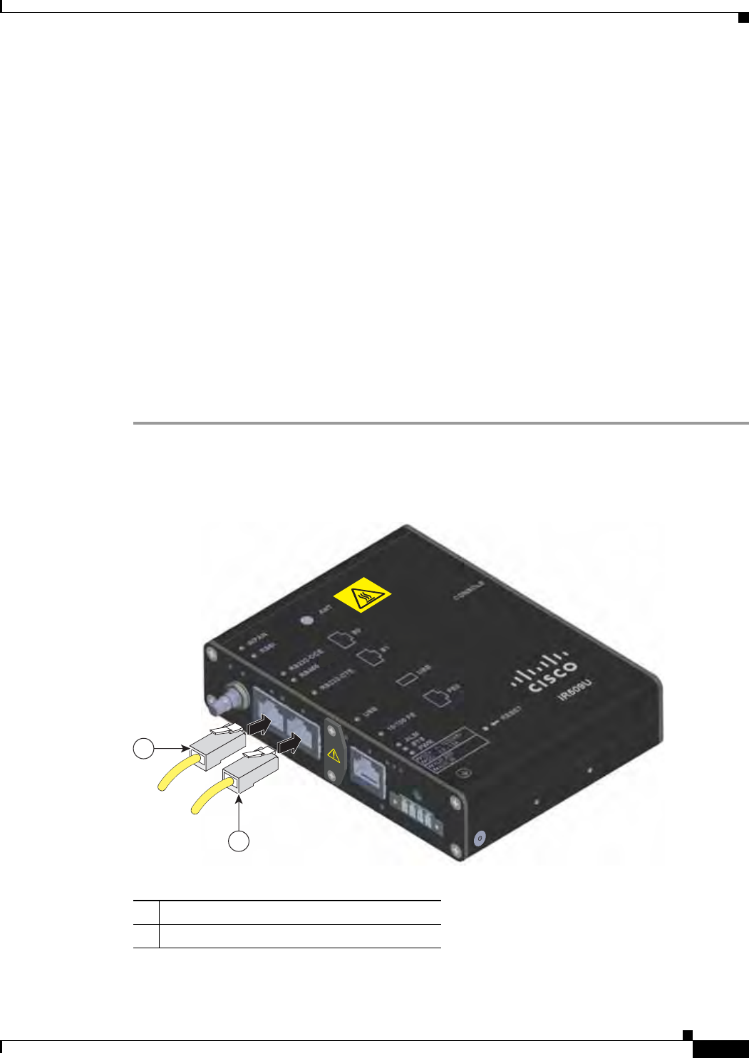
29/OCT/2014 REVIEW DRAFT — CISCO CONFIDENTIAL
2-33
Cisco IR500 Series WPAN Gateway and Range Extender Installation and Configuration Guide
Chapter 2 Installation Connecting to Device Ports
Connecting to Device Ports
• Connecting to WPAN Gateway Ports, page 2-33
• Connecting to WPAN Range Extender Ports, page 2-37
Connecting to WPAN Gateway Ports
• Connecting to the RS232DCE/RS485 or RS232-DTE Ports, page 2-33
• Connecting to the 10/100 Fast Ethernet Port, page 2-34
• Connecting to the USB Port, page 2-35
• Connecting to the Console Port, page 2-36
Connecting to the RS232DCE/RS485 or RS232-DTE Ports
To connect to the RS232DCE/RS485 or RS232-DTE Ports:
Step 1 Use a twisted four-pair, Category 5 or higher cable for connecting to the port.
Step 2 Connect the cable to the RJ-45 connector port. See Figure 2-24.
Figure 2-24 Connecting to the RS232DCE/RS485 or RS232-DTE Ports
391438
2
1
1RS232DCE/RS485 port
2RS232-DTE port
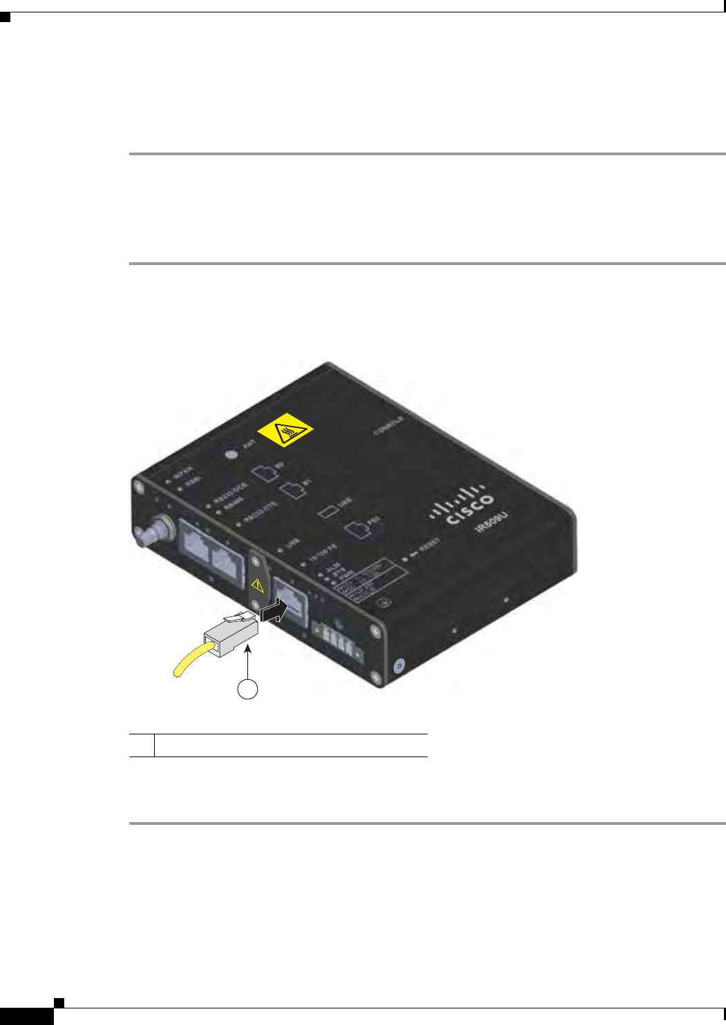
29/OCT/2014 REVIEW DRAFT — CISCO CONFIDENTIAL
2-34
Cisco IR500 Series WPAN Gateway and Range Extender Installation and Configuration Guide
Chapter 2 Installation
Connecting to Device Ports
Step 3 Connect the other end of the cable to the connecting device. For the RS232-DCE/RS485 port, the
RS232-DCE or RS485 LED turns on, depending on the type of serial communication used, when both
the gateway and the connected device have established a link. For the RS232-DTE port, the RS 232-DTE
LED turns on when both the WPAN gateway and the connected device have established a link.
Connecting to the 10/100 Fast Ethernet Port
To connect to the 10/100 Fast Ethernet port:
Step 1 Use a twisted four-pair, Category 5 or higher cable for connecting to the port.
Step 2 Connect the cable to the RJ-45 connector port. See Figure 2-25.
Figure 2-25 Connecting to the 10/100 Fast Ethernet Port
391439
1
110/100 Fast Ethernet port
Step 3 Connect the other end of the cable to the connecting device. The 10/100 FE LED turns on when both the
WPAN gateway and the connected device have established a link.
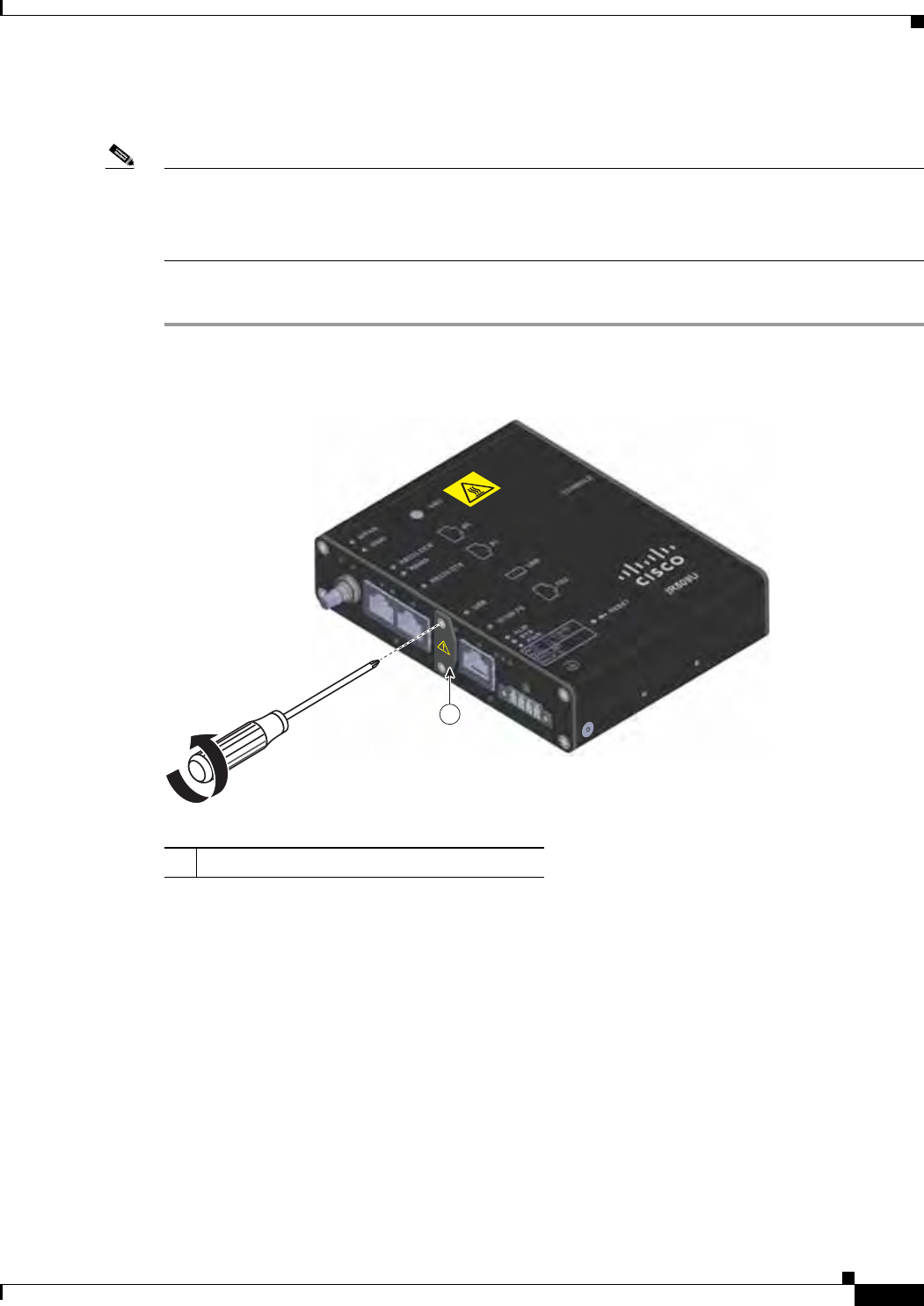
29/OCT/2014 REVIEW DRAFT — CISCO CONFIDENTIAL
2-35
Cisco IR500 Series WPAN Gateway and Range Extender Installation and Configuration Guide
Chapter 2 Installation Connecting to Device Ports
Connecting to the USB Port
Note If you are connecting to the USB port:
- a connection (to the USB port) can only be made in a non-hazardous environment
- the USB port cover must be reinstalled before the WPAN gateway can be deployed in a hazardous
environment
To connect to the USB port:
Step 1 Remove the two captive screws that attach the USB port cover to the front panel. See Figure 2-26.
Figure 2-26 Removing the USB Port Cover Captive Screws
391607
1
1USB port cover
Step 2 Connect the USB cable connector to the USB port. See Figure 2-27.
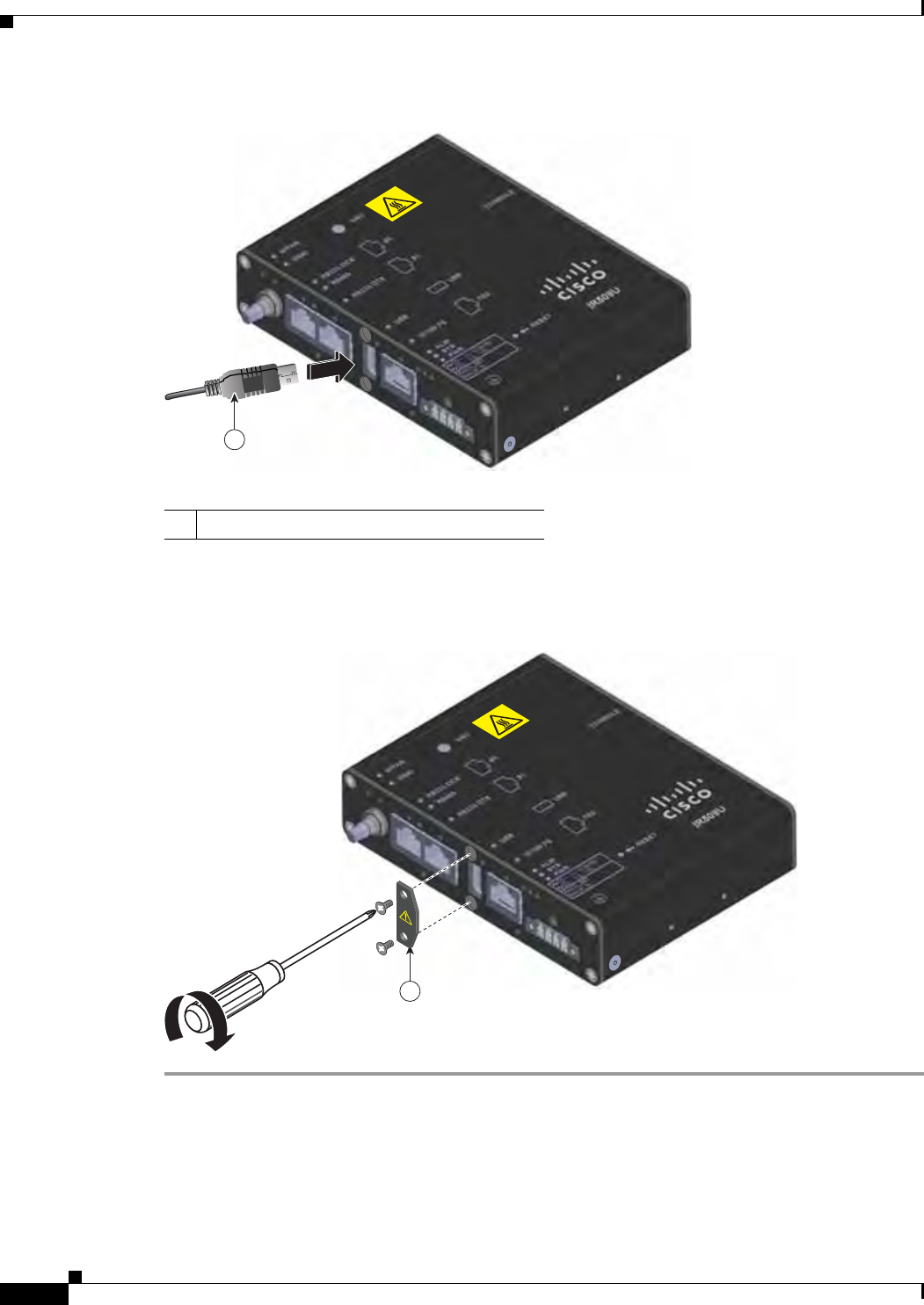
29/OCT/2014 REVIEW DRAFT — CISCO CONFIDENTIAL
2-36
Cisco IR500 Series WPAN Gateway and Range Extender Installation and Configuration Guide
Chapter 2 Installation
Connecting to Device Ports
Figure 2-27 Connecting the USB Cable Connector to the USB Port
391609
1
1USB cable connector
Step 3 When you are finished using the USB port, put the USB port cover back in place. See Figure 2-28.
Figure 2-28 Placing the USB Port Cover Back in Place
391608
1
Connecting to the Console Port
For information about connecting to the WPAN gateway console port, see the “Connecting to the WPAN
Gateway Console Port” section on page 5-13.

29/OCT/2014 REVIEW DRAFT — CISCO CONFIDENTIAL
2-37
Cisco IR500 Series WPAN Gateway and Range Extender Installation and Configuration Guide
Chapter 2 Installation Connecting to Device Ports
Connecting to WPAN Range Extender Ports
• Connecting to the Console Port, page 2-37
Connecting to the Console Port
For information about connecting to the WPAN range extender console port, see the “Connecting to the
WPAN Range Extender Console Port” section on page 5-13.

29/OCT/2014 REVIEW DRAFT — CISCO CONFIDENTIAL
2-38
Cisco IR500 Series WPAN Gateway and Range Extender Installation and Configuration Guide
Chapter 2 Installation
Connecting to Device Ports