Cisco Systems IR529UWP IR529 915Mhz WPAN IP67 Range Extender User Manual
Cisco Systems Inc IR529 915Mhz WPAN IP67 Range Extender
Contents
- 1. Users Manual
- 2. Users manual 2
- 3. Users Manual 3
- 4. Users Manual 4
Users Manual 4

CHAPTER
29/OCT/2014 REVIEW DRAFT — CISCO CONFIDENTIAL
3-1
Cisco IR500 Series WPAN Gateway and Range Extender Installation and Configuration Guide
3
Battery Backup Unit
A selection of the WPAN advanced range extender models support one battery backup unit (BBU),
which provide power to the rang extender if the AC power supply fails or is not available. For more
information about the WPAN advanced range extender models that support a BBU, see the “WPAN
Range Extender Models Supporting BBUs” section on page 3-1.
This chapter describes the BBU features and installation procedures, and includes the following
sections:
• Battery Backup Units, page 3-1
• BBU Configuration during Transportation, page 3-4
• Disabling and Enabling the BBU in the Range Extender, page 3-4
• Installing a BBU in the Range Extender, page 3-5
• BBU Technical Specifications, page 3-5
Battery Backup Units
This section contains information about:
• WPAN Range Extender Models Supporting BBUs, page 3-1
• Battery Backup Operations, page 3-2
• BBU Status, page 3-2
• Battery Backup Mode, page 3-2
• BBU Firmware Upgrade, page 3-3
WPAN Range Extender Models Supporting BBUs
Table 3-1 details the WPAN range extender models that support a BBU.

Table 3-1 WPAN Range Extender Models Supporting BBUs
WPAN Range Extender
Model Description BBU Support
IR529-WP-915S/K9 Connected Grid Basic Range Extender—IEEE 802.15.4e/g
WPAN 900 MHz No
IR529-UBWP-915S/K9 Connected Grid Advanced Range Extender, configurable
with single antenna and battery backup support—IEEE
802.15.4e/g WPAN 900 MHz
Yes (BBU is
optional)
IR529-UBWP-915D/K9 Connected Grid Advanced Range Extender, configurable
with dual antenna and battery backup support—IEEE
802.15.4e/g WPAN 900 MHz
Yes (BBU is
optional)
IR529-UWP-915D/K9 Connected Grid Advanced Range Extender, configurable
with dual antenna—IEEE 802.15.4e/g WPAN 900 MHz No
29/OCT/2014 REVIEW DRAFT — CISCO CONFIDENTIAL
3-2
Cisco IR500 Series WPAN Gateway and Range Extender Installation and Configuration Guide
Chapter 3 Battery Backup Unit
Battery Backup Units
Battery Backup Operations
The battery backup unit (BBU) provides the WPAN range extender with an emergency power source if
the AC power source is unavailable. The unit is mounted in the range extender housing.
Table 3-2describes the BBU model.
Table 3-2 BBU Models
BBU Model Description
CGR-BATT-4AH Battery backup unit, capacity = 48 Watt-hours
BBU Status
The BBU is automatically enabled and begins supplying power when the range extender detects that
power is not being received from the AC power supply. The BBU continues to supply power to the range
extender until at least one of the following conditions is met:
• BBU is completely discharged
• AC power to the range extender is enabled
• BBU is disabled via the Connected Grid Network Management System (CG-NMS) software
application.
Battery Backup Mode
This section describes impact on the range extender configuration and operating capabilities when the
range extender switches from AC power to BBU power.
The topics covered include:
• Range Extender Configuration, page 3-3
• Range Extender Interface Operation, page 3-3

29/OCT/2014 REVIEW DRAFT — CISCO CONFIDENTIAL
3-3
Cisco IR500 Series WPAN Gateway and Range Extender Installation and Configuration Guide
Chapter 3 Battery Backup Unit Battery Backup Units
Range Extender Configuration
The range extender software configuration is not impacted when the range extender switches from AC
power to BBU power.
Range Extender Interface Operation
When the BBU is operating and powering the range extender, the range extender operates and performs
normally. The range extender does not power off any interfaces to conserve power when AC power is not
available, and the range extender is being powered by the BBU.
BBU Firmware Upgrade
It is only possible to use the CG-NMS to upgrade the BBU firmware and to show information about the
BBU firmware upgrade.
To upgrade the BBU firmware and to show information about the BBU firmware upgrade, use the
CG-NMS firmware upgrade option.
The firmware upgrade is executed in background and an output message is generated in the CG-NMS
when the BBU firmware upgrade is complete. During the firmware upgrade, you can use the CG-NMS
to view the state of the BBU firmware upgrade.

29/OCT/2014 REVIEW DRAFT — CISCO CONFIDENTIAL
3-4
Cisco IR500 Series WPAN Gateway and Range Extender Installation and Configuration Guide
Chapter 3 Battery Backup Unit
BBU Configuration during Transportation
BBU Configuration during Transportation
The BBU configuration during transportation is controlled by a dedicated bit in the BBU NVRAM
register called the Transportation bit or (T-bit).
The T-Bit is set at the factory and is used to place the BBU in a disabled (low power) state. This is
necessary in order to preserve the battery charge while the WPAN range extender device (with BBU
installed) is in storage, or being transported between the factory and the final installation site.
This sections contains:
• Setting the BBU NVRAM Register T-bit, page 3-4
• BBU NVRAM Register T-bit Settings and BBU Status, page 3-4
Setting the BBU NVRAM Register T-bit
The T-bit in the BBU NVRAM register is set to 1 using the CG-NMS.
Note The T-bit is set to 1 by Cisco manufacturing at the factory. The T-bit is reset to 0 or cleared only by the
CG-NMS during ZTD deployment.
BBU NVRAM Register T-bit Settings and BBU Status
Table 3-3 BBU NVRAM T-bit Settings and BBU Status
T-bit Setting BBU Status
T-bit = 1 • AC ON: BBU enabled automatically (to allow battery to charge)
• AC OFF: BBU disabled automatically (to prevent battery from
discharging)
T-bit = 0 The BBU can be set to a disabled or enabled status for AC ON or OFF
conditions.
Note If the BBU is disabled due to being < 5% capacity, it will be
enabled automatically when AC power resumes. If the customer
disables the BBU, the customer must enable the BBU manually.
Disabling and Enabling the BBU in the Range Extender
In normal operating mode (T-bit is off), the BBU automatically begins to supply power to the range
extender when it detects that power is not being received from the AC power supply. You may wish to
disable and enable the BBU for the following reasons:
• To inhibit the BBU discharge during storage, shipping or transportation in order to preserve battery
life.
• To replace the battery in an installed and operating range extender.

29/OCT/2014 REVIEW DRAFT — CISCO CONFIDENTIAL
3-5
Cisco IR500 Series WPAN Gateway and Range Extender Installation and Configuration Guide
Chapter 3 Battery Backup Unit Installing a BBU in the Range Extender
The BBU can be disabled and enabled by using the CG-NMS. These steps are described in the following
sections:
• Disabling the BBU, page 3-5
• Enabling the BBU, page 3-5
Disabling the BBU
For information on how to disable the BBU, see the Cisco Connected Grid Network Management System
User Guide.
Enabling the BBU
For information on how to enable the BBU, see the Cisco Connected Grid Network Management System
User Guide.
Installing a BBU in the Range Extender
A BBU can only be installed in the WPAN range extender by a Cisco trained technician. Contact your
Cisco representative for support.
BBU Technical Specifications
This section describes the specifications and standards supported by the BBU.
• Range Extender Power Path Selection, page 3-5
• Discharge Conditions, page 3-6
• Charge Conditions, page 3-6
• Operating and Storage Temperatures, page 3-7
• Battery Life, page 3-7
Range Extender Power Path Selection
During normal operation, the range extender is powered by the integrated AC power supply. The BBU
enters discharge mode and begins providing power to the range extender when the AC power is
interrupted outside a range of 85V to 250V for more than 20 ms. The BBU charges or discharges only;
it does not support both simultaneously.

29/OCT/2014 REVIEW DRAFT — CISCO CONFIDENTIAL
3-6
Cisco IR500 Series WPAN Gateway and Range Extender Installation and Configuration Guide
Chapter 3 Battery Backup Unit
BBU Technical Specifications
Discharge Conditions
Table 3-4 Battery Backup Unit—Discharging Specifications
Discharge Conditions Description
Power load 4–6 W typical
Duration 8–12 hours typical
Entry to discharge1
1. All conditions met.
• AC power (range of 85V to 250V) not
detected for more than 20 ms
• Remaining BBU capacity >5%
• External ambient temperature is within
-40 to 122°F (-40 to 50°C)
Exit discharge2
2. Any condition met and system is detected.
• AC power restored in the range of
85V to 250V for more than 20 ms.
• Remaining BBU capacity <5%
• External ambient temperature is outside of
-40 to 122°F (-40 to 50°C)
Charge Conditions
Table 3-5 Battery Backup Unit—Charge Specifications
Charge Conditions Description
Power draw No more than 20 W when charging
State of charge No more than 90%
Entry to charging limit1
1. All conditions are met.
• Charge is enabled
• State of Charge (SOC) <85%
• AC power detected in the range of
85V to 250V for more than 20 ms.
• External ambient temperature is within
-4 to 104°F (-20 to 40°C)
Exit charging2
2. Any condition is met
• Charge is disabled
• AC power (range of 85V to 250V) not
detected for more than 20 ms.
• External ambient temperature is outside of
-4 to 104°F (-20 to 40°C)

29/OCT/2014 REVIEW DRAFT — CISCO CONFIDENTIAL
3-7
Cisco IR500 Series WPAN Gateway and Range Extender Installation and Configuration Guide
Chapter 3 Battery Backup Unit BBU Technical Specifications
Operating and Storage Temperatures
Table 3-6 Battery Backup Unit—Operating and Storage Temperatures
BBU State Local BBU Internal
Temperature1
1. Internal BBU heaters allow the outside ambient temperature to drop much lower than the BBU internal temperature, thereby
preserving battery life and expanding the operating temperature.
Charging +32 to 122°F (0 to 50°C) -4 to 104°F (-20 to 40°C)
Discharging -4 to 140°F (-20 to 60°C) -40 to 122°F (-40 to 50°C)
Operation (Idle) -4 to 140°F (-20 to 60°C) -40 to 122°F (-40 to 50°C)
Storage and
shipping +14 to 113°F (-10 to 45°C)
for 3 months maximum Short-term:
+14 to 113°F (-10 to 45°C) for 3 months
maximum
Long-term:
+27 to 77°F (-3 to 25°C)
- 65% Relative Humidity
- 40 to 90% SOC
Battery Life
Table 3-7 Battery Backup Unit — Battery Life
Product ID Battery Life Charge-Discharge Cycles
CGR-BATT-4AH 5 years 500
External Ambient Temperature

29/OCT/2014 REVIEW DRAFT — CISCO CONFIDENTIAL
3-8
Cisco IR500 Series WPAN Gateway and Range Extender Installation and Configuration Guide
Chapter 3 Battery Backup Unit
BBU Technical Specifications

CHAPTER
29/OCT/2014 REVIEW DRAFT — CISCO CONFIDENTIAL
4-1
Cisco IR500 Series WPAN Gateway and Range Extender Installation and Configuration Guide
4
Antenna
This chapter contains information about the antennas for the Cisco WPAN gateway and WPAN range
extender devices. The antennas provide connectivity to the CG-Mesh.
This chapter contains the following sections:
• Antennas Overview, page 4-1
• Installing or Replacing Antennas, page 4-7
Antennas Overview
• WPAN Gateway Antenna Configurations, page 4-1
• WPAN Range Extender Antenna Configurations, page 4-4
WPAN Gateway Antenna Configurations
• Gateway Pole Mounted Antenna with Below Grade Conduit Routed Cabling Configuration,
page 4-2
• Gateway Enclosure Mounted Antenna Configuration, page 4-3
• Gateway Pole Mounted Antenna with Enclosure Interface Lightning Arrestor Configuration,
page 4-4

29/OCT/2014 REVIEW DRAFT — CISCO CONFIDENTIAL
4-2
Cisco IR500 Series WPAN Gateway and Range Extender Installation and Configuration Guide
Chapter 4 Antenna
Antennas Overview
Gateway Pole Mounted Antenna with Below Grade Conduit Routed Cabling Configuration
Table 4-1 Pole Mounted Antenna with Below Grade Conduit Routed Cabling Configuration for the
IR509U-WP-915/K9 Gateway
Antenna
Arrangement and
Connector(s)
Enclosure Internal Cable Lightning Arrestor or
Adapter Outdoor Cable Antenna
Pole mounted
antenna, single
antenna cable
routed through
below grade
conduit, 1 QMA
(f) antenna
connector
Select one cable from:
• 1 RA-QMA (m) to N (m)
cable, LMR-240-FR, 10’,
Cisco PID1
1. PID = Product Identifier
CAB-L240-10-Q-N, Cisco
PN2
2. PN = Part number
37-1351-02
• 1 RA-QMA (m) to N (m)
cable, LMR-240-FR, 15’,
Cisco PID
CAB-L240-15-Q-N, Cisco
part number 37-1352-02
• 1 RA-QMA (m) to N (m)
cable, LMR-240-FR, 20’,
Cisco PID
CAB-L240-20-Q-N, Cisco
PN 37-1353-02
—A single cable
routed from inside
the enclosure to
outside the
enclosure
1 900 MHz ISM band, omni
stick, 24”, 5 dBi, N (f),
Cisco PID
ANT-WPAN-OM-OUT-N,
Cisco PN 07-1163-02

29/OCT/2014 REVIEW DRAFT — CISCO CONFIDENTIAL
4-3
Cisco IR500 Series WPAN Gateway and Range Extender Installation and Configuration Guide
Chapter 4 Antenna Antennas Overview
Gateway Enclosure Mounted Antenna Configuration
Table 4-2 Enclosure Mounted Antenna Configuration for the IR509U-WP-915/K9 Gateway
Antenna
Arrangement and
Connector(s)
Enclosure Internal Cable Lightning Arrestor or
Adapter Outdoor Cable Antenna
Antenna directly
mounted to
lightning arrestor
at enclosure
interface to
exterior, 1 QMA
(f) antenna
connector
Select one cable from:
• 1 RA-QMA (m) to N(m)
cable, LMR-240-FR, 10’,
Cisco Product Identifier
(PID) CAB-L240-10-Q-N,
Cisco PN 37-1351-02
• 1 RA-QMA (m) to N(m)
cable, LMR-240-FR, 15’,
Cisco PID
CAB-L240-15-Q-N, Cisco
PN 37-1352-02
• 1 RA-QMA (m) to N(m)
cable, LMR-240-FR, 20’,
Cisco PID
CAB-L240-20-Q-N, Cisco
PN 37-1353-02
1 lightning arrestor,
N (f)-N (f), Cisco
PID
CGR-LA-NF-NF,
Cisco PN
07-1158-01
—1 900 MHz ISM band, omni
stick, 8”, 1.5 dBi, N (f),
Cisco PID
ANT-WPAN-OD-OUT-N,
Cisco PN 07-1318-01

29/OCT/2014 REVIEW DRAFT — CISCO CONFIDENTIAL
4-4
Cisco IR500 Series WPAN Gateway and Range Extender Installation and Configuration Guide
Chapter 4 Antenna
Antennas Overview
Gateway Pole Mounted Antenna with Enclosure Interface Lightning Arrestor Configuration
Table 4-3 Pole Mounted Antenna with Enclosure Interface Lightning Arrestor Configuration for the
IR509U-WP-915/K9 Gateway
Antenna
Arrangement and
Connector(s)
Enclosure Internal Cable Lightning Arrestor or
Adapter Outdoor Cable Antenna
Pole mounted
antenna, lightning
arrestor at
enclosure interface
to exterior,
antenna exterior
and internal cables
used, 1 QMA (f)
antenna connector
Select one cable from:
• 1 RA-QMA (m) to
N(m) cable,
LMR-240-FR, 10’,
Cisco Product
Identifier (PID)
CAB-L240-10-Q-N
, Cisco PN
37-1351-02
• 1 RA-QMA (m) to
N(m) cable,
LMR-240-FR, 15’,
Cisco PID
CAB-L240-15-Q-N
, Cisco PN
37-1352-02
• 1 RA-QMA (m) to
N(m) cable,
LMR-240-FR, 20’,
Cisco PID
CAB-L240-20-Q-N
, Cisco PN
37-1353-02
1 lightning arrestor, N
(f)-N (f), Cisco PID
CGR-LA-NF-NF, Cisco
PN 07-1158-01
Select one option from:
• 1 RA-N(m) to N(m)
cable, LMR-400-DB,
5’, Cisco PID
CAB-L400-5-N-N,
Cisco PN 37-1436-01
• 1 N(m) to N(m)
cable, LMR-400-DB,
5’, Cisco PID
CAB-L400-5-N-NS,
Cisco PN 37-1446-01
• 2 RA-N(m) to N(m)
cables,
LMR-400-DB, 20’,
Cisco PID
CAB-L400-20-N-N,
Cisco PN 37-1392-01
• 2 RA-N(m)-N(m)
cables,
LMR-600-DB, 30’,
Cisco PID
CAB-L600-30-N-N,
Cisco PN 37-1396-01
1 900 MHz ISM band,
omni stick, 24”, 5 dBi,
N (f), Cisco PID
ANT-WPAN-OM-OUT-
N, Cisco PN
07-1163-02
WPAN Range Extender Antenna Configurations
• Basic Range Extender Antenna Configuration, page 4-5
• Single Antenna Advanced Range Extender—Direct Connect Antenna Configuration, page 4-5
• Single Antenna Advanced Range Extender—Pole Mounted Antenna Configuration, page 4-6
• Dual Antenna Advanced Range Extender—Dual Antenna Configuration, page 4-6

29/OCT/2014 REVIEW DRAFT — CISCO CONFIDENTIAL
4-5
Cisco IR500 Series WPAN Gateway and Range Extender Installation and Configuration Guide
Chapter 4 Antenna Antennas Overview
Basic Range Extender Antenna Configuration
Table 4-4 Antenna Configuration for the IR529-WP-915S/K9 Basic Range Extender
Antenna
Arrangement and
Connector(s)
Enclosure
Internal
Cable
Lightning Arrestor or
Adapter Outdoor Cable Antenna
Single antenna,
1 N (f) antenna
connector
—Select one option from:
• None— when using a
1.5 dBi direct connect
antenna
• 1 Lightning Arrestor,
DC Pass, N (m)-N (f),
Cisco PID
CGR-LA-NM-NF,
Cisco PN 07-1091-01
Select one option from:
• None—when using a 1.5 dBi
direct connect antenna
• 1 RA-N (m) to N (m) cable,
LMR-400-DB, 5’, Cisco
PID CAB-L400-5-N-N,
Cisco PN 37-1436-01
• 1 N(m) to N(m) cable,
LMR-400-DB, 5’, Cisco
PID CAB-L400-5-N-NS,
Cisco PN 37-1446-01
• 2 RA-N(m) to N(m) cables,
LMR-400-DB, 20’, Cisco
PID CAB-L400-20-N-N,
Cisco PN 37-1392-01
• 2 RA-N(m)-N(m) cables,
LMR-600-DB, 30’, Cisco
PID CAB-L600-30-N-N,
Cisco PN 37-1396-01
Select one antenna from:
• 1 900 MHz ISM band,
omni stick, 8”, 1.5 dBi,
N (m), Cisco PID
ANT-WPAN-OD-
OUT-N, Cisco PN
07-1318-01
• 1 900 MHz ISM band,
omni stick, 24”, 5 dBi, N
(f), Cisco PID
ANT-WPAN-OM-OUT-
N, Cisco PN 07-1163-02
Single Antenna Advanced Range Extender—Direct Connect Antenna Configuration
Table 4-5 Direct Connect Antenna Configuration for the IR529-UBWP-915S/K9 Single Antenna Advanced Range
Extender
Antenna
Arrangement and
Connector(s)
Enclosure
Internal
Cable
Lightning Arrestor or
Adapter Outdoor Cable Antenna
Direct connect
single antenna,
1 N (f) connector
—None None Select one antenna from:
• 1 900 MHz ISM band,
omni stick, 8”, 1.5 dBi,
N(m), Cisco PID
ANT-WPAN-OD-
OUT-N, Cisco PN
07-1318-01

29/OCT/2014 REVIEW DRAFT — CISCO CONFIDENTIAL
4-6
Cisco IR500 Series WPAN Gateway and Range Extender Installation and Configuration Guide
Chapter 4 Antenna
Antennas Overview
Single Antenna Advanced Range Extender—Pole Mounted Antenna Configuration
Table 4-6 Mast Mounted Antenna Configuration for the IR529-UBWP-915S/K9 Single Antenna Advanced Range
Extender
Antenna
Arrangement and
Connector(s)
Enclosure
Internal
Cable
Lightning Arrestor or
Adapter Outdoor Cable Antenna
Pole mounted
single antenna, 1
N (f) antenna
connector
—1 Lightning Arrestor, DC
Pass, N (m)-N (f), Cisco
PID CGR-LA-NM-NF,
Cisco PN 07-1091-01
Select one option from:
• 1 RA-N (m) to N (m) cable,
LMR-400-DB, 5’, Cisco
PID CAB-L400-5-N-N,
Cisco PN 37-1436-01
• 1 N (m) to N (m) cable,
LMR-400-DB, 5’, Cisco
PID CAB-L400-5-N-NS,
Cisco PN 37-1446-01
• 2 RA-N (m) to N (m) cables,
LMR-400-DB, 20’, Cisco
PID CAB-L400-20-N-N,
Cisco PN 37-1392-01
• 2 RA-N (m)-N (m) cables,
LMR-600-DB, 30’, Cisco
PID CAB-L600-30-N-N,
Cisco PN 37-1396-01
1 900 MHz ISM band, omni
stick, 24”, 5 dBi, N (f), Cisco
PID
ANT-WPAN-OM-OUT-N,
Cisco PN 07-1163-02
Dual Antenna Advanced Range Extender—Dual Antenna Configuration
Note The dual antenna configuration applies to the dual antenna advanced range extender models with and
without battery support:
- IR529-UBWP-915D/K9 (with battery support
- IR529-UWP-915D/K9 (without battery support)

Table 4-7 Dual Antenna Configuration for the IR529-UBWP-915D/K9 and IR529-UWP-915D/K9 Dual Antenna
Advanced Range Extenders
Antenna
Arrangement and
Connector(s)
Enclosure
Internal
Cable
Lightning Arrestor or
Adapter Outdoor Cable Antenna
Dual antenna,
2 N (f) antenna
connectors
—2 Lightning Arrestors, N
(m)-N (f), Cisco PID
CGR-LA-NM-NF, Cisco
PN 07-1091-01
Select one option:
• 2 RA-N (m) to N (m) cables,
LMR-400-DB, 20’, Cisco
PID CAB-L400-20-N-N,
Cisco PN 37-1392-01
• 2 RA-N (m)-N (m) cables,
LMR-600-DB, 30’, Cisco
PID CAB-L600-30-N-N,
Cisco PN 37-1396-01
2 900 MHz ISM Band,
directional Yagi antennas, 10
dBi, N (f), Cisco PID
ANT-WPAN-OD-OUT-N,
Cisco PN 07-1328-01
29/OCT/2014 REVIEW DRAFT — CISCO CONFIDENTIAL
4-7
Cisco IR500 Series WPAN Gateway and Range Extender Installation and Configuration Guide
Chapter 4 Antenna Additional Information for WPAN Gateway Antenna Installations
Additional Information for WPAN Gateway Antenna
Installations
For all outdoor antenna/WPAN gateway installations, the coax shield should be grounded (earthed) in
accordance with ANSI/NFPA 70, the National Electrical Code (NEC), in particular Section 820.93,
Grounding of Outer Conductive Shield of a Coaxial Cable.
In addition, please refer to Section 820.93 of the National Electrical Code, ANSI/NFPA 70: 2005; and
EN60728-11: 2005, which provide guidelines for proper grounding and, in particular, specify that the
coaxial cable shield shall be connected to the grounding system of the building, as close to the point of
cable entry as practical.
For indoor antenna/WPAN gateway installations, no additional considerations are required.
Installing or Replacing Antennas
Depending on the configuration you specified, the WPAN gateway and WPAN range extender could be
shipped with all required antennas already installed and connected. You may need to install an antenna
when you purchase an antenna separately to replace a faulty or damaged antenna.
For procedures and safety information required to install or replace antennas, see the Connected Grid
Antenna Installation Guide, at: www.cisco.com/go/cg-modules.

29/OCT/2014 REVIEW DRAFT — CISCO CONFIDENTIAL
4-8
Cisco IR500 Series WPAN Gateway and Range Extender Installation and Configuration Guide
Chapter 4 Antenna
Installing or Replacing Antennas

CHAPTER
29/OCT/2014 REVIEW DRAFT — CISCO CONFIDENTIAL
5-1
Cisco IR500 Series WPAN Gateway and Range Extender Installation and Configuration Guide
5
Operation and Configuration
This chapter describes the operation of the WPAN gateway and WPAN range extender and how to
configure the devices:
• Information about WPAN Gateway and WPAN Range Extender Operation, page 5-1
• WPAN Gateway and WPAN Range Extender Data Flow, page 5-3
• Information about Raw Socket Transport and MAP-T, page 5-5
• Information about WPAN Gateway and WPAN Range Extender Configuration, page 5-11
• Configuring the WPAN Gateway and WPAN Range Extender, page 5-12
• CG-NMS WPAN Device Management Related Operations, page 5-20
Information about WPAN Gateway and WPAN Range Extender
Operation
• WPAN Gateway and WPAN Range Extender and the Cisco Field Area Network, page 5-1
• Role of the WPAN Gateway and WPAN Range Extender in the Cisco FAN, page 5-2
WPAN Gateway and WPAN Range Extender and the Cisco Field Area Network
The WPAN gateway and WPAN range extender operate in the Cisco Connected Grid (CG) Field Area
Network (FAN).
The FAN solution provides an urban-scale IPv6-based networking solution for connecting and managing
a multitude of devices in a smartgrid architecture. The Cisco CG FAN consists of three components:
• Connected Grid Endpoint (CGE) devices
• Connected Grid Router (CGR) devices
• Connected Grid Network Management System (CG-NMS)
CGEs are the CG FAN end points. The CGEs may be electric meters, or Distribution Automation (DA)
devices. The CG FAN utilizes low-cost mesh networking technology to connect CGEs. The link
technologies may utilize Radio Frequency (e.g. IEEE 802.15.4g) and, or Power Line Communication
(e.g. IEEE P1901.2) media.

29/OCT/2014 REVIEW DRAFT — CISCO CONFIDENTIAL
5-2
Cisco IR500 Series WPAN Gateway and Range Extender Installation and Configuration Guide
Chapter 5 Operation and Configuration
Information about WPAN Gateway and WPAN Range Extender Operation
CGRs provide wide-area connectivity for CGEs. In addition to providing wide-area connectivity,
because CGRs typically have more resources than CGEs, CGRs support critical functions for secure
network access control, routing, and management of CGEs. In a typical deployment, a single CGR may
provide wide-area connectivity for hundreds or thousands of CGEs.
CG-NMS provides the necessary back-end infrastructure for supporting the CGEs and CGRs in the
Cisco CG FAN. CG-NMS is responsible for managing secure network access, configurations, and
firmware updates for all CGR and CGEs in a CG FAN deployment. Each device registers with the
CG-NMS and periodically reports information that assists a network operator in assessing the health of
the network and diagnosing any issues that may occur.
The Cisco Industrial Routers (IR) 500 Series WPAN Gateway and WPAN Range Extender provide
unlicensed 902-to-928 MHz ISM-band wireless personal area network (WPAN) communications to
diverse Internet of things (IoT) applications. Among the IoT applications supported are smart grid,
distribution automation (DA), and supervisory control and data acquisition (SCADA).
The devices supply radio frequency (RF) mesh connectivity to one IPv4/Ethernet and serial IoT device,
including recloser control, cap bank control, voltage regulator controls, and other remote terminal units
(RTUs).
The devices provide an open standards RF mesh solution based on the following standards:
• IEEE 802.15.4 g/e
• IETF 6LoWPAN
• IETF Routing Protocol for Low Power and Lossy Networks (RPL)
• IETF Mapping of Address and Port—Translation (MAP-T)
• IETF Constrained Application Protocol (CoAP)
Role of the WPAN Gateway and WPAN Range Extender in the Cisco FAN
• Role of the WPAN Gateway, page 5-2
• Role of the WPAN Range Extender, page 5-3
Role of the WPAN Gateway
The WPAN Gateway provides IPv4/IPv6 connectivity to DA Devices. The gateway connects to DA
Devices using serial ports (RS232/RS485) and, or an Ethernet port using IPv4. The gateway provides
remote connectivity to:
• serial DA devices over CG-Mesh by transporting serial data in TCP/IP
• IPv4 DA devices over the IPv6-based CG-Mesh by using Mapping of Address and Port using
Translation (MAP-T), as specified in draft-ietf-software-map-t
WPAN Gateway and Serial-based DA Devices
The CGR800-WPAN connects serial-based DA devices and exports them over the IPv6-based Field Area
Network by the following means:
• RS232/RS485 Port—the gateway RS232/RS485 serial port is used to connect RS232/RS485-based
DA devices and transport serial data traffic over TCP. The gateway configuration and management
of the serial port is done via CSMP and the CG-NMS.

29/OCT/2014 REVIEW DRAFT — CISCO CONFIDENTIAL
5-3
Cisco IR500 Series WPAN Gateway and Range Extender Installation and Configuration Guide
Chapter 5 Operation and Configuration WPAN Gateway and WPAN Range Extender Data Flow
• RS232 Port—the gateway RS232 serial port is used to connect RS232-based DA devices and
transport serial data traffic over TCP. The gateway configuration and management of the serial port
is done via CSMP and the CG-NMS.
• Raw TCP Serial Transport—the CGR800-WPAN makes the bi-directional serial data stream for the
serial ports available over IPv6 via the IEEE 802.15.4g interface.
WPAN Range Extender and Ethernet-based DA Devices
The WPAN gateway connects IPv4-based DA devices to the IPv6-based FAN by the following means:
• Ethernet Port—the gateway Ethernet port is used to provide IPv4 connectivity to DA devices. The
gateway exports configuration and management of the Ethernet port via CSMP and the CG-NMS.
• DHCP—the CGR800-WPAN implements a DHCP Server to support dynamic configuration of
IPv4-based DA devices. The CGR800-WPAN exports DHCP configuration and management via
CSMP.
• Mapping of Address and Port using Translation (MAP-T)—The gateway provides shared or
uniquely addressed IPv4 host connectivity to and across an IPv6 domain using MAP-T. The gateway
implements the MAP Customer Edge (CE) functionality, as described in draft-ietf-software-map-t.
Each MAP domain must also include a device that implements the MAP Border Router (BR)
functionality (e.g. ASR-1000). The gateway configuration and management of MAP-T is done via
CSMP and the CG-NMS.
• NAT44—The gateway uses NAT44 to translate private IPv4 addresses used by DA devices
connected to the Ethernet port to public IPv4 addresses used with MAP-T.
Role of the WPAN Range Extender
The WPAN range extender is an IEEE 802.15.4g-2012 IPv6 router device that allows additional
flexibility in locating IEEE 802.15.4g devices, resulting in extra connectivity among CG-Mesh devices.
For example, while CG-Mesh electric meters must be placed where electric metering occurs, the range
extender may be placed anywhere AC power is available. The range extenders support the full CG-Mesh
network platform, including IEEE 802.15.4g, IEEE 802.1X, IPv6, and RPL.
WPAN Gateway and WPAN Range Extender Data Flow
• Data Flow Prerequisites, page 5-3
• Data Flow Paradigms, page 5-4
Data Flow Prerequisites
The mandatory components for a Cisco IR 500 Series WPAN gateway and WPAN range extender
deployment are:
• Cisco ASR 1000 router configured as a MAP-T border router
• Cisco CGR 1000 router configured as a WPAN router (a WPAN module is installed)
• Cisco IR 500 series WPAN gateway and WPAN range extender configured and installed
29/OCT/2014 REVIEW DRAFT — CISCO CONFIDENTIAL
5-4
Cisco IR500 Series WPAN Gateway and Range Extender Installation and Configuration Guide
Chapter 5 Operation and Configuration
WPAN Gateway and WPAN Range Extender Data Flow
Data Flow Paradigms
There are two potential data flow paradigms with the WPAN gateway and WPAN range extender devices:
• Serial DA device remote connectivity over CG-Mesh by transporting serial data in TCP/IP—this is
achieved by routing traffic between a WPAN gateway serial port attached DA device and an
application server through a Raw Socket connection
• IPv4 DA device remote connectivity over the IPv6-based CG-Mesh by using Mapping of Address
and Port using Translation (MAP-T)—this is achieved by routing traffic between a WPAN gateway
Ethernet port connected IPv4 DA device and an application server
Both traffic flows involves MAP-T enabling non-IPv6 traffic to be transparently forwarded over
6LoWPAN, or the mesh network that is IPv6 only.
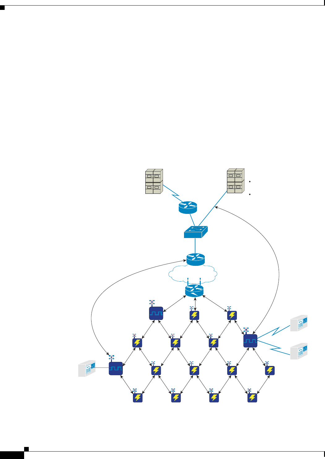
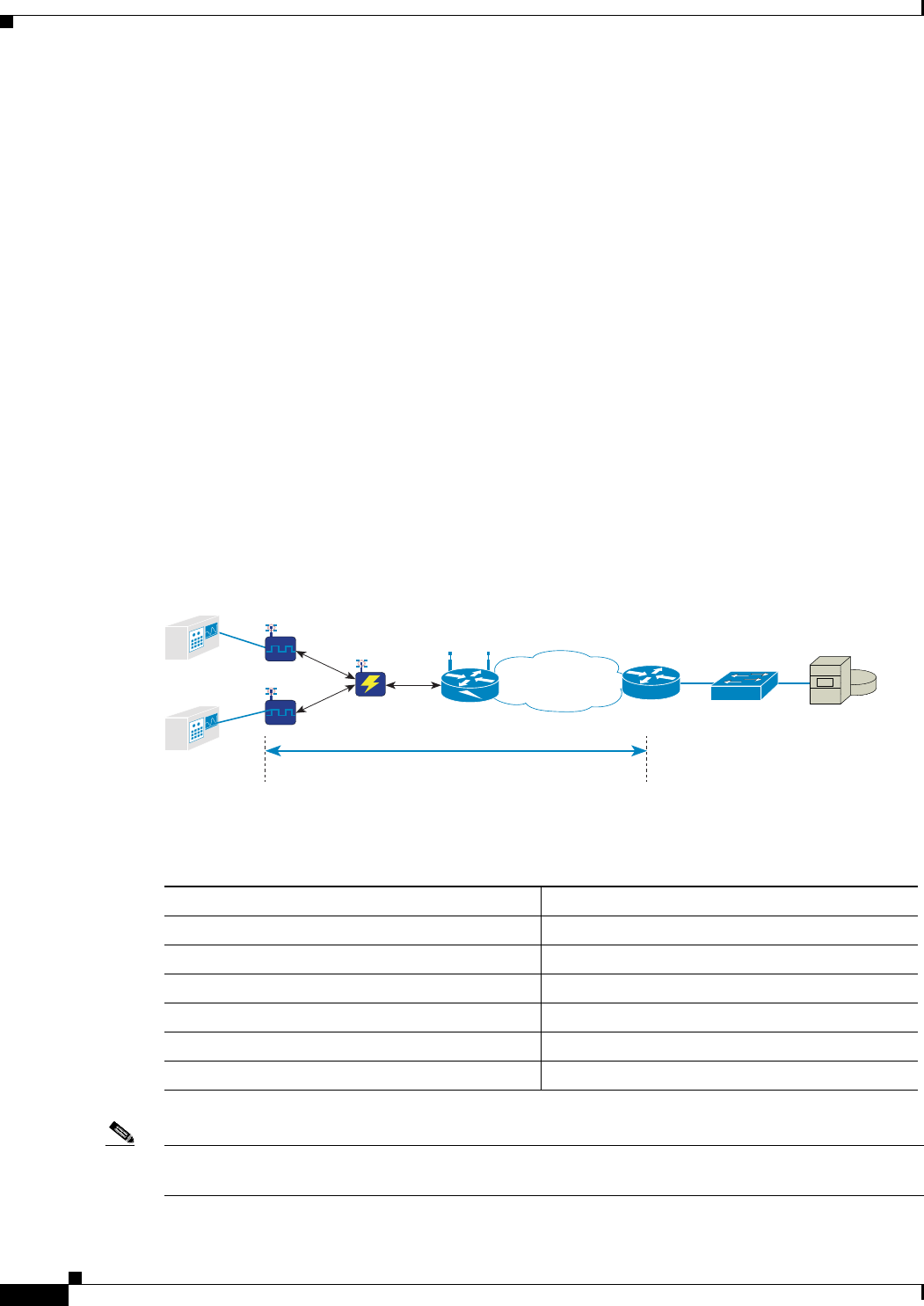
Figure 5-1 shows the deployment of the WPAN gateway and WPAN range extender devices and the role
of Raw Socket and MAP-T.
Figure 5-1 WPAN Gateway and WPAN Range Extender Deployment
CGR 2010
(Raw TCP Server)
SCADA/DMS server
Raw TCP Session for
Serial protocols
Standard-based IPv4 over
IPv6 - IETF MAP-T
SCADA SCADA
IP WAN
CGR 1000
WPAN
Gateway
WPAN
Gateway
WPAN
Gateway
Real Time Unit (RTU)
RTUs
WPAN Range ExtenderWPAN Range Extender
Raw TCP: natively or through
IP/Serial Redirector SW
Native IPv4 SCADA protocol
391923

29/OCT/2014 REVIEW DRAFT — CISCO CONFIDENTIAL
5-5
Cisco IR500 Series WPAN Gateway and Range Extender Installation and Configuration Guide
Chapter 5 Operation and Configuration Information about Raw Socket Transport and MAP-T
For more information about Raw Socket and MAP-T, see the “Information about Raw Socket Transport
and MAP-T” section on page 5-5.
Information about Raw Socket Transport and MAP-T
• Raw Socket, page 5-5
• MAP-T, page 5-8
Raw Socket
Raw Socket is a method for transporting serial data through an IP network. It transports streams of
characters from one serial interface to another over an IP network for utility applications.The feature can
be used to transport Supervisory Control and Data Acquisition (SCADA) data from Remote Terminal
Units (RTUs). For the WPAN gateway and WPAN range extender deployment, Raw Socket Transport
uses TCP as the transport protocol.
Raw Socket Transport supports the following for each asynchronous serial interface:
• TCP as the transport protocol, with built-in auto TCP connection retry mechanism.
• Interface configuration as either a server or a client. The WPAN gateway can only be set up as a
server or as a client but not both simultaneously.
• One server per interface, but multiple clients.
Note For the one server per interface with multiple clients arrangement, the number of clients may be limited
to one or two. Contact Cisco for more information.
For more information about the Raw Socket deployment read the following sections:
• TCP Transport, page 5-5
• Raw Socket Configurations, page 5-6
• Raw Socket and Serial Protocol Operation, page 5-7
TCP Transport
The TCP transport CG FAN scenario is that one router acts as a Raw Socket server, listening for TCP
connection requests from the other CG FAN routers, which are configured as Raw Socket clients. in
Figure 5-1, for example, the CGR 2010 acts as the Raw socket server, and it listens for TCP connection
requests from the WPAN gateways, which are configured as Raw Socket clients.
A Raw Socket client receives streams of serial data from the RTUs and accumulates this data in its buffer,
then places the data into packets, based on user-specified packetization criteria. The Raw Socket client
initiates a TCP connection with the Raw Socket server and sends the packetized data across the IP
network to the Raw Socket server, which retrieves the serial data from the packets and sends it to the
serial interface, and on to the utility management system.
29/OCT/2014 REVIEW DRAFT — CISCO CONFIDENTIAL
5-6
Cisco IR500 Series WPAN Gateway and Range Extender Installation and Configuration Guide
Chapter 5 Operation and Configuration
Information about Raw Socket Transport and MAP-T
Raw Socket Configurations
Raw Socket transport uses a client-server model on the WPAN gateway. The WPAN gateway can be
either a server or a client but not both. At most one server and multiple clients can be configured on a
single asynchronous serial line.
Figure 5-2, Figure 5-3, and Figure 5-4 show three different Raw Socket configurations and scenarios
involving the WPAN gateway. In these examples, serial data is transferred between RTUs and a utility
management system across an IP network that includes several CGR 1000 and CGR 2010 routers.
Figure 5-2 Raw Socket and Client/Server Setup on Routers
Application communicates
through COM ports
CGR 1000
Series Routers
(Clients)
CGR 2010
(Server)
RS232 or
RS485
IP Infrastructure
Serial interfaces
SCADA
Server
391924
RTUs
WPAN Range
Extenders
WPAN
Gateways
(Clients)
Raw Socket Master and
Client set-up on routers
In Figure 5-2, a Raw Socket CGR1000 router client receives streams of serial data from the WPAN
gateway attached RTUs and accumulates the data before placing it into packets. The CGR 2010 router
acts as a Raw Socket server, listening for TCP connection requests from the WPAN gateway, which are
configured as Raw Socket clients.The WPAN gateway Raw Socket client initiates a TCP connection with
the CGR2010 Raw Socket server, and sends the packetized data across the IP network to the CGR2010
Raw Socket server, which retrieves the serial data from the packets and sends it to the serial interface,
and on to the SCADA server.
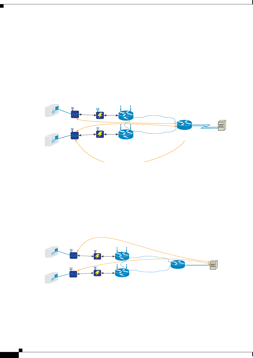
Figure 5-3 Raw Socket Client/Server Setup between Routers and SCADA Server with IP/Serial
Redirector Software
Raw Socket Master and Client set-up
between routers and SCADA server
Application communicates
through COM ports mapped
to IPv4 and TCP ports by
IP/Serial redirector software
(as long as the WPAN
gateway does not support
Raw Socket UDP)
CGR 1000
Series Routers
(Clients)
CGR 2010
(Server)
IP Infrastructure
Ethernet
SCADA
Server
391925
RS232 or
RS485
RTUs
WPAN Range
Extenders
WPAN
Gateways
(Clients)
In Figure 5-3, a Raw Socket CGR1000 router client receives streams of serial data from the WPAN
gateway attached RTUs and accumulates the data before placing it into packets. The CGR1000 Raw
Socket clients initiates a TCP connection with the SCADA server, and sends the packetized data across
the IP network to the SCADA server. The SCADA server communicates through COM ports mapped to
IP and TCP/UDP ports, by IP/Serial Redirector software.
29/OCT/2014 REVIEW DRAFT — CISCO CONFIDENTIAL
5-7
Cisco IR500 Series WPAN Gateway and Range Extender Installation and Configuration Guide
Chapter 5 Operation and Configuration Information about Raw Socket Transport and MAP-T
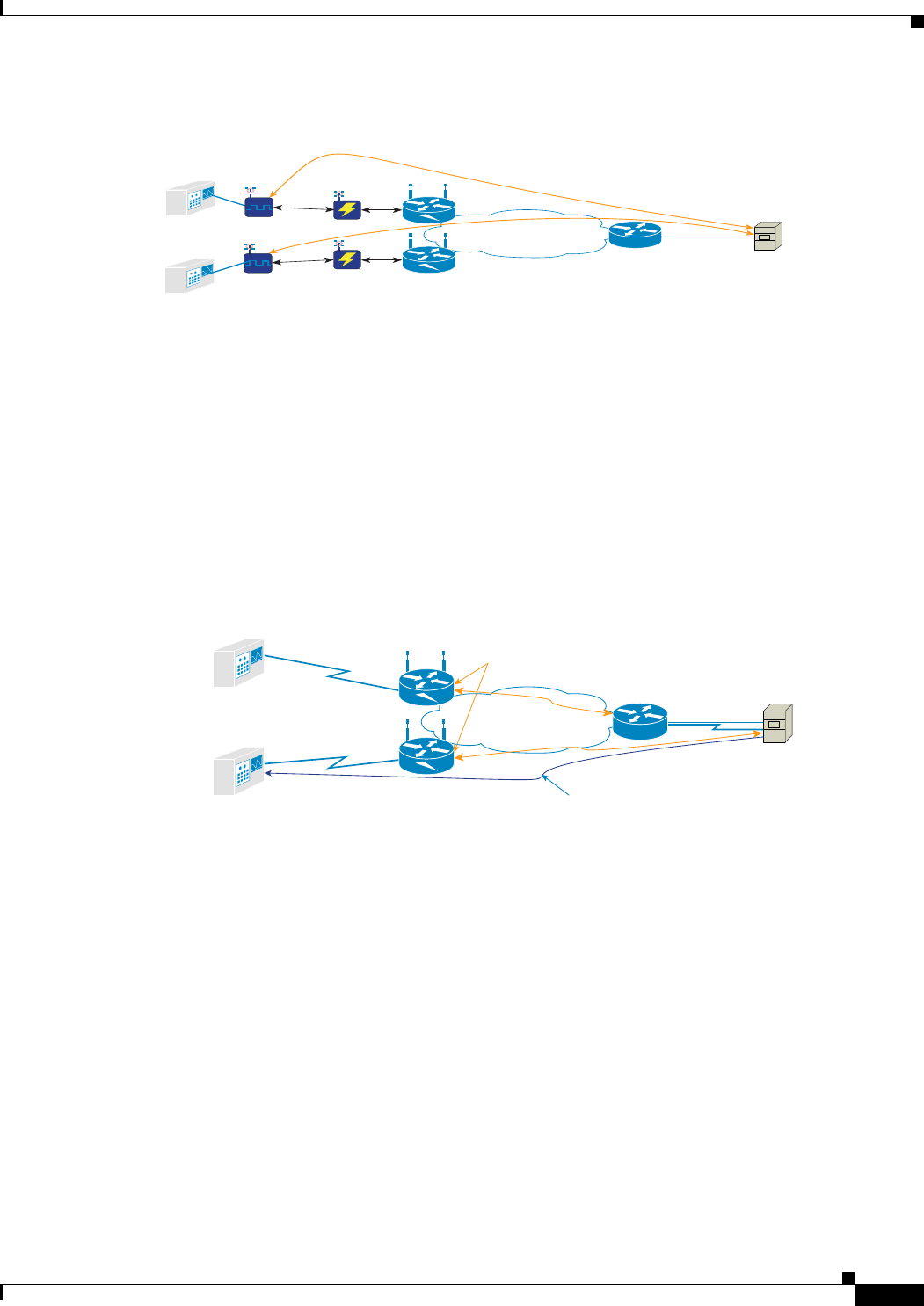
Figure 5-4 Raw Socket Client/Server Setup between Routers and SCADA Server with Direct
RAW Socket Communication
Raw Socket Master and Client set-up
between routers and SCADA server
Application communicates directly
over Raw Socket (IP + TCP/UDP ports)
IP Infrastructure
Ethernet
SCADA
Server
391929
RS232 or
RS485
RTUs
WPAN Range
Extenders
WPAN
Gateways
(Clients)
CGR 2010
(Server)
CGR 1000
Series Routers
(Clients)
In Figure 5-4, a Raw Socket CGR1000 router client receives streams of serial data from the WPAN
gateway attached RTUs and accumulates the data before placing it into packets. The CGR1000 Raw
Socket clients initiates a TCP connection with the SCADA server, and sends the packetized data across
the IP network to the SCADA server. The SCADA server communicates directly over Raw Socket IP and
TCP/UDP ports.
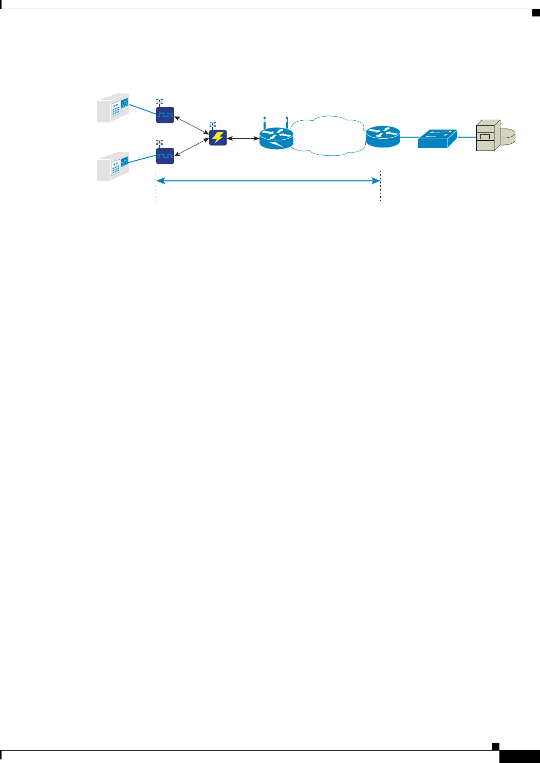
Raw Socket and Serial Protocol Operation
Figure 5-5 shows a Raw Socket DA deployment scenario involving a SCADA server, WPAN range
extenders, and WPAN gateways with RTUs attached to the serial ports.
Figure 5-5 Raw Socket and Serial Protocol
WPAN Gateway Remote
Terminal Units (RTUs)
(Clients)
Raw Socket connection
Serial protocol connection
RS232 or
RS485
IP
Infrastructure
Ethernet
SCADA
Server
391926
When running a serial protocol over a Raw Socket, there are two different layers that establish their own
connectivity:
• Raw Socket layer—Assuming the SCADA server handles the Raw Socket session (the other
alternative is the Raw Socket is handled by a router), the Raw Socket session is established between
the SCADA server and the WPAN gateway. One side is the listener (Raw Socket TCP server), the
other is the client (Raw Socket TCP client).
• Serial protocol layer—The serial protocol session, i.e. DNP3, IEC 60870-5-101, Modbus, etc., runs
on the serial protocol layer, and this also has server/master and client sides. This serial protocol
session runs from the SCADA server to the attached device (RTU).

29/OCT/2014 REVIEW DRAFT — CISCO CONFIDENTIAL
5-8
Cisco IR500 Series WPAN Gateway and Range Extender Installation and Configuration Guide
Chapter 5 Operation and Configuration
Information about Raw Socket Transport and MAP-T
MAP-T
6LoWPAN is an IPv6-only adaptation layer for the physical (PHY) and media access control (MAC)
layer technologies implementing it. No IPv4 adaptation layer is defined for these PHY and MAC layers,
so the Mapping of Address and Port using Translation (MAP-T) architecture is used as an IPv4-IPv6
translation mechanism. The “mapping of address and port” mechanism defines how IPv4 nodes can
communicate over an IPv6-only infrastructure.
MAP-T was developed as a transition mechanism due to IPv4 address exhaustion, MAP-T is based on a
double stateless NAT64 translation. It specifies a stateless algorithmic address and transport layer port
mapping scheme, and allows embedding of IPv4 address and port numbers in an IPv6 address when
forwarding the IPv4 traffic across an IPv6-only network.
The use of MAP-T in the WPAN gateway enables the use of a same address, if required by a customer,
on the attached field devices since IPv4 traffic coming through the Ethernet port will go through NAT44.
By using MAP-T, the WPAN gateway is using an open standard to integrate non-IP and IPv4
communications over 6LOWPAN/RPL networks.
In a Field Area Network (FAN) scenario, where hundreds of WPAN gateways are deployed across
multiple Field Area Routers (FARs), such as CGR 1000, a MAP-T domain begins at the WPAN gateway
level and ends with the head-end aggregation routers, such as ASR1000 as shown in Figure 5-6.
29/OCT/2014 REVIEW DRAFT — CISCO CONFIDENTIAL
5-9
Cisco IR500 Series WPAN Gateway and Range Extender Installation and Configuration Guide
Chapter 5 Operation and Configuration Information about Raw Socket Transport and MAP-T
Figure 5-6 MAP-T in a FAN and WPAN Gateway Scenario
RTUs
WPAN Range
Extender
CGR 1000
MAP-T Domain
MAP-T
Border Relay
ASR 1000
SCADA
Server
IP WAN
391927
WPAN
Gateways
There are defined IPv6 and IPv4 MAP-T prefixes inside the MAP-T domain enabling the NAT64
translation process to identify addresses to be translated, as well as get proper reachability and routing
through the MAP-T domain.
NAT44 is a component of the MAP solution, but the NAT44 in MAP differs from traditional NAT44
deployments in that instead of assigning a public IPv4 address range to each field device for translation
(in the case of NAT), or a single public IPv4 address for translation (in the case of Port Address
Translation (PAT)) to each field device, it extends the granularity beyond a single public IPv4 address,
by being able to assign a port range to each of the field devices sharing the same IPv4 public address.
This unique address and port range combination is then translated into the IPv6 address space when
transitioning into the IPv6 domain using the MAP field device. The MAP algorithm still retains the
ability to assign the full IPv4 address or an IPv4 prefix to the MAP field device, but the WPAN gateway
only leverages the full IPv4 address to be allocated on a per WPAN gateway basis.
MAP-T Mapping Rules and Map Domain Parameters
Inside the MAP-T domain are defined IPv6 and IPv4 MAP-T prefixes enabling the NAT64 translation
process to identify addresses to be translated as well as get proper reachability and routing through the
MAP-T domain. Those are known as:
• MAP-T Default Mapping Rule (DMR): an IPv6 prefix used to address all destinations outside the
MAP-T domain.
–
DMR IPv6 prefix and prefix length embeds any IPv4 addresses outside the MAP-T domain. For
example, within a MAP-T domain using a DMR IPv6 prefix = 2610:D0:1200:CAFE::/64, all
IPv4 translated packet sources and destinations outside the MAP-T domain have an IPv6
address based on this prefix, i.e. sending packets to IPv4 100.1.1.2 translated to IPv6
2610:d0:1200:cafe:64:101:200:0. The SCADA server IPv4 address is an example of a
destination outside of the MAP-T domain.
• MAP-T Basic Mapping Rule (BMR): the IPv6 and IPv4 prefixes used to address MAP-T nodes
inside the MAP-T domain
–
BMR IPv4 prefix and prefix length are the IPv4 subnet selected to address all IPv4 nodes in a
MAP-T domain. For example, a MAP-T domain set-up with 153.10.10.0/24 as IPv4 subnet has
all IPv4 nodes configured with IPv4 address from this subnet, BMR IPv4 prefix = 153.10.10.0
and prefix length = 24
29/OCT/2014 REVIEW DRAFT — CISCO CONFIDENTIAL
5-10
Cisco IR500 Series WPAN Gateway and Range Extender Installation and Configuration Guide
Chapter 5 Operation and Configuration
Information about Raw Socket Transport and MAP-T
–
BMR IPv6 prefix and prefix length are used to embed the IPv4 address of nodes inside the
MAP-T domain. For example, a MAP-T domain is configured with a MAP-T IPv6 BMR =
2031:6f8:147e:10::/56. Packets sent or received from IPv4 nodes inside the MAP-T domain
have a translated IPv6 address based on this prefix, i.e. 2031:6f8:147e:10fe:99:a0a:fe00:0 for a
MAP-T IPv4 node set-up with IPv4 153.10.10.254.
–
BMR Share ratio: MAP-T being designed for various deployment scenarios, it could be feasible
to allocate to a MAP-T node either an IPv4 prefix (smaller than the MAP-T BMR IPv4 prefix),
or a single IPv4 address (/32) or share a single IPv4 address (/32) between several nodes. In the
later case, it requires indicating how many bits for port numbers are assigned, which is called
“BMR share ratio”. In case of IR 500 deployment, it is recommended to use a single IPv4
address (/32) per IR 500 with a share ratio = 1 to keep the addressing simple.
–
BMR Embedded Address (EA) bits indicate – in the case of share ration = 1 – the length of the
IPv4 suffix embedded in the MAP-T IPv6 End-user IPv6 prefix. For example, in case of an IPv4
/24 prefix allocated to a MAP-T domain, the BMR EA value derived from it is 8.
MAP-T Addressing Rules Example
Figure 5-7 is an example of a MAP-T domain, and the domain parameters are provided in Table 5-1. The
Table 5-2 details the translated addresses.
Figure 5-7 MAP-T Domain
CGR 1000
MAP-T Domain
MAP-T
Border Relay
ASR 1000 SCADA
Server
IP WAN
391928
RTUs
WPAN Range
Extender
WPAN
Gateways
The Default Mapping Rule is 2610:D0:1200:CAFE::/64.
Table 5-1 MAP-T Domain Parameters
MAP-T Domain Parameter Setting
Rule IPv6 Prefix 2031:6F8:147E:1000::
Rule IPv6 Prefix length /56
Rule IPv4 Prefix 153.10.10.0
Rule IPv4 Prefix Length /24
Share Ratio 1
EA bits length 8
Note If EA bits + Rule IPv4 prefix lengths are equal to 32, then a full IPv4 address is to be assigned. The
address is created by concatenating the Rule IPv4 prefix and the EA-bits.

29/OCT/2014 REVIEW DRAFT — CISCO CONFIDENTIAL
5-11
Cisco IR500 Series WPAN Gateway and Range Extender Installation and Configuration Guide
Chapter 5 Operation and Configuration Information about WPAN Gateway and WPAN Range Extender Configuration
Note End-user IPv6 prefix = Rule IPv6 Prefix + IPv4 Suffix (EA bits field)
Table 5-2 Translated Addresses
Case No. MAP IPv4 address End-user IPv6 prefix MAP IPv6 address
1153.10.10.1 2031:6f8:147e: 1001:: 2031:6f8:147e:1001:99:a0a:100:0
2153.10.10.2 2031:6f8:147e:1002:: 2031:6f8:147e:1002:99:a0a:200:0
3153.10.10.32 2031:6f8:147e: 1020:: 2031:6f8:147e:1020:99:a0a:2000:0
4153.10.10.254 2031:6F8:147E:10fe:: 2031:6f8:147e: 10fe:99:a0a:fe00:0
Information about WPAN Gateway and WPAN Range Extender
Configuration
• Role of CG-NMS, page 5-11
• CG-NMS Device Classification, page 5-11
• CSMP Client, page 5-12
• Role of CG-DM, page 5-12
Role of CG-NMS
The IR500 series WPAN gateway and WPAN range extender are managed and configured by the
Connected Grid Network Management System (CG-NMS) application.
CG-NMS Device Classification
CG-NMS uses groups to manage devices. Each device must be classified into a group.
For CG-NMS based management and configuration, the WPAN gateway and WPAN range extender are
classified according to the device category, device type, and group information in Table 5-3.
Table 5-3 Classification Information for IR 500 Series Devices
Classification Entity Classification Information
DeviceCategory Endpoint
deviceType ir500
default config group default-ir500
default firmware group default-ir500
tunnel provisioning group Not applicable

29/OCT/2014 REVIEW DRAFT — CISCO CONFIDENTIAL
5-12
Cisco IR500 Series WPAN Gateway and Range Extender Installation and Configuration Guide
Chapter 5 Operation and Configuration
Configuring the WPAN Gateway and WPAN Range Extender
CSMP Client
CSMP Client is a GUI field tool used to manage and monitor the WPAN gateway and WPAN range
extender hardware and networking information.
The “GET” function in the field tool is used to obtain status and performance information about the
devices in real time. The “POST” function is used to set device parameters in real time.CSMP Client can
be used as a diagnostic tool to check a single device or the whole mesh network.
The field tool has two connection modes to connect a WPAN gateway or WPAN range extender:
• Point-to-Point Protocol (PPP) over Serial console port
• IPv6 through WPAN network
Role of CG-DM
CG-DM is a GUI field tool used to troubleshoot, configure and to update firmware images on WPAN
Gateway devices.
Configuring the WPAN Gateway and WPAN Range Extender
• Accessing the Configuration through the Console Port, page 5-12
• Uploading a Device to CG-NMS, page 5-16
• Registering with CG-NMS, page 5-17
• Configuring an IR 500 Series Device with CG-NMS, page 5-17
Accessing the Configuration through the Console Port
You can access the WPAN gateway or WPAN range extender configuration by connecting to the console
port on either device.
Warning
Do not connect or disconnect cables to the ports while power is applied to the switch or any device
on the network because an electrical arc can occur. This could cause an explosion in hazardous
location installations. Be sure that power is removed from the switch and cannot be accidentally be
turned on, or verify that the area is nonhazardous before proceeding.
Statement 1070
Warning
If you connect or disconnect the console cable with power applied to the switch or any device on the
network, an electrical arc can occur. This could cause an explosion in hazardous location
installations. Be sure that power is removed or the area is nonhazardous before proceeding.
Statement
1080
• Connecting to the WPAN Gateway Console Port, page 5-13
• Connecting to the WPAN Range Extender Console Port, page 5-13
29/OCT/2014 REVIEW DRAFT — CISCO CONFIDENTIAL
5-13
Cisco IR500 Series WPAN Gateway and Range Extender Installation and Configuration Guide
Chapter 5 Operation and Configuration Configuring the WPAN Gateway and WPAN Range Extender
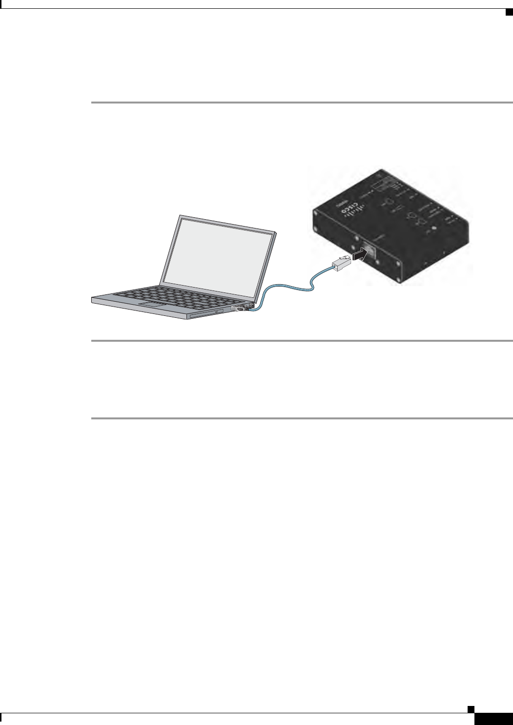
Connecting to the WPAN Gateway Console Port
To connect to the WPAN gateway console port:
Step 1 Connect the RJ-45-to-DB-9 adapter cable to the 9-pin serial port on the PC. Connect the other end of the
cable to the WPAN gateway console port.
Figure 5-8 Connecting the Console Cable
391433
Connecting to the WPAN Range Extender Console Port
To connect to the WPAN gateway range extender:
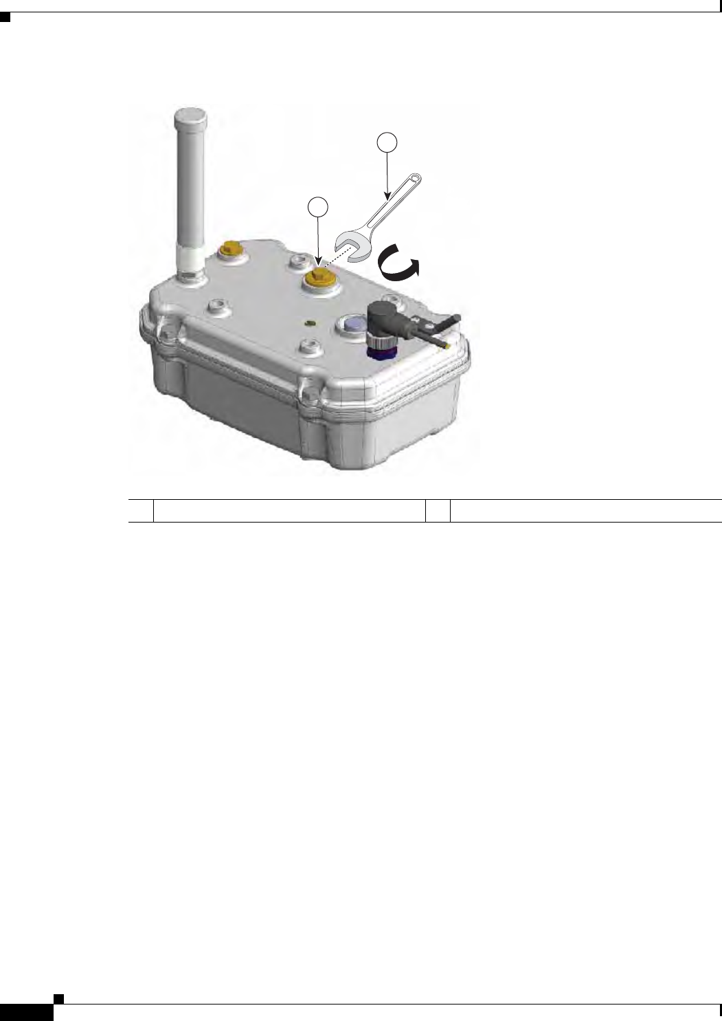
Step 1 Use a 0.5 in. (13 mm) socket wrench to remove the console port cover. See Figure 5-9.
29/OCT/2014 REVIEW DRAFT — CISCO CONFIDENTIAL
5-14
Cisco IR500 Series WPAN Gateway and Range Extender Installation and Configuration Guide
Chapter 5 Operation and Configuration
Configuring the WPAN Gateway and WPAN Range Extender
Figure 5-9 Removing the Console Port Cover
1
2
391430
1Console port cover 10.5 in. (13 mm) Socket wrench
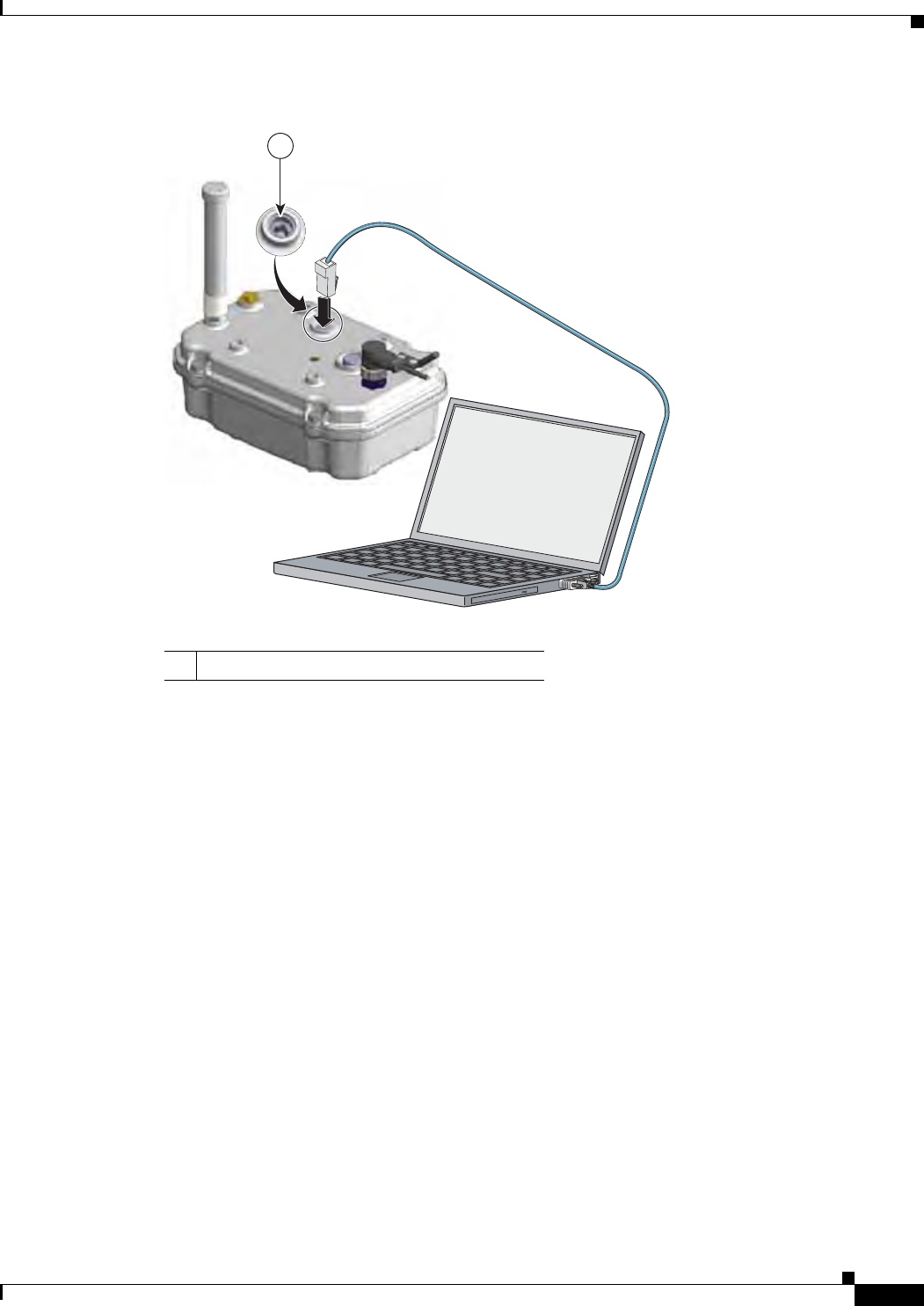
Step 2 Connect the RJ-45-to-DB-9 adapter cable to the 9-pin serial port on the PC. Connect the other end of the
cable to the WPAN range extender console port. See Figure 5-10.
29/OCT/2014 REVIEW DRAFT — CISCO CONFIDENTIAL
5-15
Cisco IR500 Series WPAN Gateway and Range Extender Installation and Configuration Guide
Chapter 5 Operation and Configuration Configuring the WPAN Gateway and WPAN Range Extender
Figure 5-10 Connecting the Console Cable
391432
1
1Console port
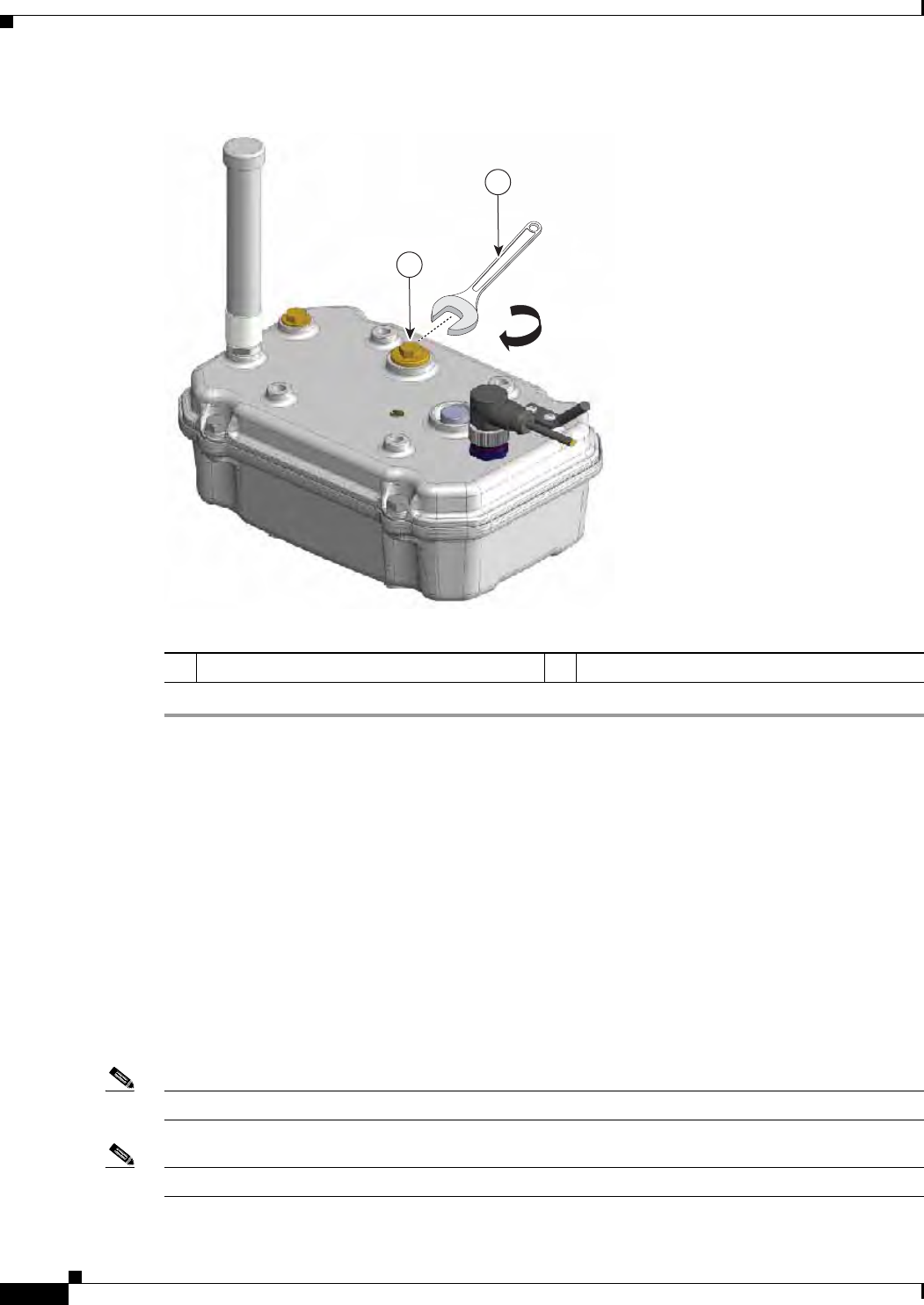
Step 3 When you are finished configuring the WPAN range extender, disconnect the cable from the console
port, and place the console port cover back on the console port to cover it. Use a 0.5 in. (13 mm) socket
wrench to torque the console port cover to 6-7 ft-lbs (8.13-9.49 N-m). See Figure 5-11.
29/OCT/2014 REVIEW DRAFT — CISCO CONFIDENTIAL
5-16
Cisco IR500 Series WPAN Gateway and Range Extender Installation and Configuration Guide
Chapter 5 Operation and Configuration
Configuring the WPAN Gateway and WPAN Range Extender
Figure 5-11 Covering the Console Port
1
391429
2
1Console port cover 20.5 in. (13 mm) Socket wrench
Uploading a Device to CG-NMS
WPAN gateway and WPAN range extender devices can be uploaded to CG-NMS using a Device
Properties CSV file. For more information see the “Common Device Operations” section of the Cisco
Connected Grid Network Management System User Guide.
A sample file content for a WPAN gateway device is:
eid, deviceType, endUserIPv6Prefix, endUserIPv6PrefixLen, lat, lng
00173b12003d003b, ir500, 2001:dead:beaf:2::,64,12,12
A sample file for a WPAN range extender is:
eid, deviceType, lat, lng
00173b12003d003b,ir500,12,12
Note The WPAN range extender does not require an endUserIPv6Prefix.
Note eid: Is the EUI64 version of the MAC of WPAN interface of the device

29/OCT/2014 REVIEW DRAFT — CISCO CONFIDENTIAL
5-17
Cisco IR500 Series WPAN Gateway and Range Extender Installation and Configuration Guide
Chapter 5 Operation and Configuration Configuring the WPAN Gateway and WPAN Range Extender
endUserIPv6Prefix and endUserIPv6PrefixLen are described in the configuration section below.
Every uploaded WPAN gateway and WPAN range extender device is put in the "default-ir500" config
and firmware groups if a group name is not specified in the csv.
Registering with CG-NMS
WPAN gateway and WPAN range extender devices use CSMP for communicating with CG-NMS. The
registration process involves handshaking between the devices and the CG-NMS.
During registration, CG-NMS pushes a configuration file from a user defined CG-NMS configuration
file to each device.
You use a configuration template to define the configuration file for each group dedicated to the WPAN
gateway and WPAN range extender devices. The configuration file and its contents are pushed to the
devices when they register with CG-NMS.
Configuring an IR 500 Series Device with CG-NMS
During registration, CG-NMS pushes the user defined configuration from the "template" to each device.
You can also initiate an on demand configuration push to all devices in the group using a "Push
Configuration” option in CG-NMS.
For more information see the “Editing the ENDPOINT Configuration Template” and the “Pushing
Configurations to Endpoints” sections of the Cisco Connected Grid Network Management System User
Guide.
The configuration tasks include:
• Configuring Serial Interface Settings, page 5-17
• Configuring MAP-T Settings, page 5-18
• Configuring Raw Socket Settings, page 5-18
• Configuring Mesh Link Settings, page 5-19
• Configuring NAT44, page 5-19
Configuring Serial Interface Settings
The WPAN gateway serial interface settings include:
–
Media Type (RS232 or RS485)
–
Parity
–
Baud Rate
–
Stop Bit
–
Data bits
–
Flow control
For more information see the “Editing the ENDPOINT Configuration Template” section of the Cisco
Connected Grid Network Management System User Guide.

29/OCT/2014 REVIEW DRAFT — CISCO CONFIDENTIAL
5-18
Cisco IR500 Series WPAN Gateway and Range Extender Installation and Configuration Guide
Chapter 5 Operation and Configuration
Configuring the WPAN Gateway and WPAN Range Extender
Configuring MAP-T Settings
The MAP-T settings for the WPAN gateway are:
–
DefaultMapping IPv6 Prefix
–
IPv4 Prefix
–
IPv6 Prefix Length
–
IPv4 Prefix Length
–
EA Bits Length
For more information see the “Editing the ENDPOINT Configuration Template” section of the Cisco
Connected Grid Network Management System User Guide.
MAP-T Settings for a WPAN Gateway in FAN
Note On the Cisco IOS ASR1000 and CGR1000, MAP-T rules are set-up by indicating the following MAP-T
domain rules:
- IPv6 BMR
- IPv4 BMR
- IPv6 DMR
On the WPAN gateway, the MAP-T IPv6 is an End-user IPv6 prefix that integrates the MAP-T BMR
IPv6 rules + IPv4 suffix value, the length being based on the BMR EA length value.
For example, a CG-NMS CSV file for a WPAN gateway contains:
eid,devicetype,lat,lng,meshPanid,status,endUserIPv6Prefix,endUserIPv6PrefixLen
00173B1500340036,ir500,37.4187911,-121.9196689,10,unheard,2019:1111:2222:1000::,48
The file content can be read as:
• IPv6 BMR = 2019:1111:2222::
• IPv6 BMR prefix length = 48
• IPv6 End-User prefix = IPv6 BMR = 2019:1111:2222:1000:: giving the WPAN gateway an IPv4
address = MAP-T IPv4 prefix = CG-NMS set-up + IPv4 suffix = 10 (or .16 decimal)
Configuring Raw Socket Settings
The Raw Socket settings for the WPAN gateway are:
• Initiator—Designates the device as the client or server (initiator = 0—denotes server; initiator = 1,
2, 3 etc—denotes client)
• TCP idle timeout (min)—Sets the time to maintain an idle connection
• Local port—Sets the port number of the device
• Peer port—Sets the port number of the client/server connected to the device
• Peer IP address—Sets the IP address to the host connected to the device
• Connect timeout—Sets the TCP client connect timeout for Initiator DA Gateway devices
For more information, see the “Editing the ENDPOINT Configuration Template” and the “Raw Sockets
Metrics and Sessions” sections of the Cisco Connected Grid Network Management System User Guide.

29/OCT/2014 REVIEW DRAFT — CISCO CONFIDENTIAL
5-19
Cisco IR500 Series WPAN Gateway and Range Extender Installation and Configuration Guide
Chapter 5 Operation and Configuration Configuring the WPAN Gateway and WPAN Range Extender
Configuring Mesh Link Settings
For configuring mesh link settings such as ‘Mesh SSID’ and ‘Transmit Power’ see the “Managing
Devices” chapter of the Cisco Connected Grid Network Management System User Guide.
Configuring NAT44
Note This section only applies to the WPAN gateway.
NAT44 settings for the WPAN gateway can be configured. In order to configure NAT44 properties you
can edit the device template or use the import a CSV file method.
For more information see the “Editing the ENDPOINT Configuration Template” or “Adding a File to
CG-NMS” sections of the Cisco Connected Grid Network Management System User Guide
The following fields can be specified:
• nat44InternalAddress0
• nat44InternalPort0
• nat44ExternalPort0
where 0-3 are four valid map index.
You must make sure that the config group that the device belongs to has Ethernet enabled. You can select
the Enable Ethernet checkbox and save the config template for the config group before the config push.
Because all three fields for a map index are required values, all three fields must be specified for the
Nat44 configuration to be applied.
Default values of 127.0.0.1, 0, 0 respectively have to be explicitly specified from CSV for a device in
case any of the other settings for a particular map index need not be configured.
If an invalid IPv4 address or other invalid values for a port is specified then NAT44 settings for that par-
ticular map index will be ignored during config push.
Related CGR 1000 and ASR 1000 Configurations
• Configuring Raw Socket Configuration on CGR 1000 Series and CGR 2010 Routers, page 5-19
• Configuring the WPAN Settings on CGR 1000 Series Routers, page 5-20
• Configuring an IPv6 DHCP Address Pool on CGR 1000 Series Routers, page 5-20
• Configuring MAP-T on ASR 1000 Routers, page 5-20
• Configuring IPv6 Routing on the CGR 1000 Series and ASR 1000 Routers, page 5-20
Configuring Raw Socket Configuration on CGR 1000 Series and CGR 2010 Routers
For information about configuring Raw Socket on the CGR 1000 series and ASR 1000 routers, see the
following guides:
• Raw Socket Transport Software Configuration Guide for Cisco 1000 Series Connected Grid Routers
(Cisco IOS)

29/OCT/2014 REVIEW DRAFT — CISCO CONFIDENTIAL
5-20
Cisco IR500 Series WPAN Gateway and Range Extender Installation and Configuration Guide
Chapter 5 Operation and Configuration
CG-NMS WPAN Device Management Related Operations
• “Raw Socket Transport” chapter of Cisco 1000 Series Connected Grid Routers SCADA Software
Configuration Guide
• Configuring Raw Socket Protocol on the CGR 2010 Router
Configuring the WPAN Settings on CGR 1000 Series Routers
An SSID and PAN ID must be configured on the CGR1000 series router. For information about
configuring and SSID and PAN ID, see the Cisco Connected Grid WPAN Module for CGR 1000 Series
Installation and CG-Mesh Configuration Guide on Cisco.com.
Configuring an IPv6 DHCP Address Pool on CGR 1000 Series Routers
The IPv6 addresses of the WPAN gateway and WPAN range extender are allocated from a central
DHCPv6 server during the process of joining the mesh. The CGR1000 router only needs to be configured
as a DHCPv6 Relay.
For information about configuring the CGR 1000 series router as a DHCP relay, see the “Configuring
IPv6 DHCP Relay” section of the Cisco Connected Grid WPAN Module for CGR 1000 Series
Installation and CG-Mesh Configuration Guide.
Configuring MAP-T on ASR 1000 Routers
MAP-T must be configured on the ASR 1000 router.
For information about configuring MAP-T on the ASR 1000 series router, see the “Mapping of Address
and Port Using Translation” chapter of the IP Addressing: NAT Configuration Guide, Cisco IOS XE
Release 3S (ASR 1000).
Configuring IPv6 Routing on the CGR 1000 Series and ASR 1000 Routers
IPv6 routing needs to be configured on the CGR 1000 series and ASR 1000 routers. For information
about configuring IPv6 on the CGR 1000 series and ASR 1000 routers, see the following guides:
• “Configuring IPv6 Multicast Agent” chapter of Cisco Connected Grid WPAN Module for CGR 1000
Series Installation and CG-Mesh Configuration Guide
• “IPv6 Routing: OSPFv3” chapter of IP Routing: OSPF Configuration Guide, Cisco IOS XE Release
3S (Cisco ASR 1000)
• “IPv6 Policy-Based Routing” chapter of IP Routing: Protocol-Independent Configuration Guide,
Cisco IOS XE Release 3S (ASR 1000)
• IP Routing: BGP Configuration Guide, Cisco IOS XE Release 3S (Cisco ASR 1000)
• “IPv6 Routing: Static Routing” chapter of IP Routing: Protocol-Independent Configuration Guide,
Cisco IOS XE Release 3S (ASR 1000)
CG-NMS WPAN Device Management Related Operations
• Performing Periodic Inventory, page 5-21
• Uploading Firmware, page 5-22
• Creating Rules and Events, page 5-22

29/OCT/2014 REVIEW DRAFT — CISCO CONFIDENTIAL
5-21
Cisco IR500 Series WPAN Gateway and Range Extender Installation and Configuration Guide
Chapter 5 Operation and Configuration CG-NMS WPAN Device Management Related Operations
Performing Periodic Inventory
Depending on the report periodic interval set in the configuration template, devices report regular
inventory metrics to CG-NMS using CSMP. CG-NMS stores the reported properties and metrics.
For more information, see the “Configuring Rules” section of the Cisco Connected Grid Network
Management System User Guide.
The properties and metrics of a sample WPAN device reported include:
• Inventory
–
Name
–
EID
–
Device Category
–
Manufacturer
–
Status
–
IP Address
–
Last Heard
–
Last Property Heard
–
Last Metric Heard
–
Model Number
–
Serial Number
–
Firmware Version
–
Config Group
–
Firmware Group
–
Location
–
Labels
–
Meter Certificate
• Mesh Device Health
–
Uptime
• Mesh Link Settings
–
SSID
–
PANID
–
Transmit Power
–
Security Mode
• Mesh Link Metrics
–
Mesh Link Transmit Speed
–
Mesh Link Receive Speed
–
Mesh Link Transmit Packet Drops
–
Mesh route RPL Hops
–
Mesh Route RPL Link Cost

29/OCT/2014 REVIEW DRAFT — CISCO CONFIDENTIAL
5-22
Cisco IR500 Series WPAN Gateway and Range Extender Installation and Configuration Guide
Chapter 5 Operation and Configuration
CG-NMS WPAN Device Management Related Operations
–
Mesh Route RPL Path Cost
–
Mesh Route RSSI
–
Mesh Route Reverse RSSI
• Network Routes Metrics
• Routing Path Metrics
• Raw Socket Metrics
• MAP-T Information
Uploading Firmware
Uploading of firmware to WPAN gateway and WPAN range extender devices can be performed by the
CG-NMS. You can:
• Upload ir500 firmware images to CG-NMS via the GUI.
• Execute a firmware upload to a specific group of devices.
• Perform “Set Backup” and “Schedule Reload” operations.
For more information, see the “Configuring Devices” and “Pushing Configurations to Endpoints”
sections of the Cisco Connected Grid Network Management System User Guide.
Creating Rules and Events
You can create rules and events for WPAN gateway and WPAN range extender devices using CG-NMS.
For more information, see the “Configuring Rules” section of the Cisco Connected Grid Network
Management System User Guide.

A-1
Cisco IR500 Series WPAN Gateway and Range Extender Installation and Configuration Guide
APPENDIX
29/OCT/2014 REVIEW DRAFT — CISCO CONFIDENTIAL
A
Technical Specifications
This appendix provides the technical specification for the Cisco WPAN gateway and Cisco WPAN range
extender devices. The sections include:
• Environmental and Operational Specifications, page A-1
• Power Specifications, page A-3
• Alarm Ratings, page A-3
• Mechanical Specifications, page A-4
• Hazardous Location Specifications, page A-5
• Declaration of Conformity for RF Exposure, page A-5
Environmental and Operational Specifications
• WPAN Gateway Environmental and Operational Specifications, page A-1
• WPAN Range Extender Environmental and Operational Specifications, page A-2
WPAN Gateway Environmental and Operational Specifications
Table A-1 Environmental and Operating Specifications for WPAN Gateway
Description Specification
Operating Temperature –40 to 158 °F (–40 to 70 °C)
Altitude 3000 M
Humidity IP30 Rated, Non-condensing
Storage Temperature -40C to +85C
Storage Altitude 3000 M
Vibration Per IEEE 1613 and IEC 61850
Shock Per IEEE 1613 and IEC 61850
Seismic Per IEC 61850

29/OCT/2014 REVIEW DRAFT — CISCO CONFIDENTIAL
A-2
Cisco IR500 Series WPAN Gateway and Range Extender Installation and Configuration Guide
Appendix A Technical Specifications
Environmental and Operational Specifications
WPAN Range Extender Environmental and Operational Specifications
• Basic Range Extender, page A-2
• Advanced Range Extender, page A-2
Basic Range Extender
Table A-2 describes the environmental and operating specifications for the basic range extender model
(IR529-WP-915S/K9).
Table A-2 Environmental and Operating Specifications for Basic WPAN Range Extender
Description Specification
Operating Temperature –40 to 140 °F (–40 to 60 °C)
Altitude 3000 M
Humidity IP67 Rated
Storage Temperature -40C to +85C
Storage Altitude 3000 M
Vibration Per IEEE 1613 and IEC 61850
Shock Per IEEE 1613 and IEC 61850
Seismic Per IEC 61850
Advanced Range Extender
Table A-3 describes the environmental and operating specifications for the following advanced range
extender models:
• IR529-UBWP-915S/K9
• IR529-UBWP-915D/K9
• IR529UWP-915D/K9
Table A-3 Environmental and Operating Specifications for Advanced WPAN Range Extender
Description Specification
Operating Temperature –40 to 158 °F (–40 to 70 °C)
Altitude 3000 M
Humidity IP67 Rated
Storage Temperature -40C to +85C
Storage Altitude 3000 M
Vibration Per IEEE 1613 and IEC 61850
Shock Per IEEE 1613 and IEC 61850
Seismic Per IEC 61850

29/OCT/2014 REVIEW DRAFT — CISCO CONFIDENTIAL
A-3
Cisco IR500 Series WPAN Gateway and Range Extender Installation and Configuration Guide
Appendix A Technical Specifications Power Specifications
Power Specifications
• WPAN Gateway Power Requirements, page A-3
• WPAN Range Extender Power Requirements, page A-3
WPAN Gateway Power Requirements
Table A-4 WPAN Gateway Power Requirements
Description Specification
DC Input Voltage • Maximum Operating Range:
2.3 A @ 9.5 VDC to 0.33 A @60 VDC
• Nominal: 12, 24, or 48 VDC
Maximum DC Input Voltage Rating • 0.33 A@ 60 VDC
• 0.4 A @ 48 VDC
• 0.75 A @ 24 VDC
• 1.5 A @ 12 VDC
WPAN Range Extender Power Requirements
Table A-5 WPAN Range Extender Power Requirements
Description Specification
AC Input Voltage 90–264 VAC
Maximum Rated Current Draw • IR529-WP-915S/K9: 1 A
• IR529-UBWP-915S/K9: 1 A
• IR529-UBWP-915D/K9: 1 A
• IR529UWP-915D/K9: 1 A
Maximum Power Consumption • IR529-WP-915S/K9: 12 W
• IR529-UBWP-915S/K9: 18 W
• IR529-UBWP-915D/K9: 18 W
• IR529UWP-915D/K9: 12 W
Alarm Ratings
Table A-6 lists the alarm ratings for the Cisco WPAN gateway.

Table A-6 WPAN Gateway Alarm Ratings
Alarm Ratings Specification
Alarm input electrical specification • States: Open or Closed Circuit
• Wire: 24 AWG to 18 AWG
29/OCT/2014 REVIEW DRAFT — CISCO CONFIDENTIAL
A-4
Cisco IR500 Series WPAN Gateway and Range Extender Installation and Configuration Guide
Appendix A Technical Specifications
Mechanical Specifications
Mechanical Specifications
• WPAN Gateway Mechanical Specifications, page A-4
• WPAN Range Extender Mechanical Specifications, page A-4
WPAN Gateway Mechanical Specifications
Table A-7 WPAN Gateway Mechanical Specifications
Characteristic Specification
Enclosure Type IP30 enclosure
Dimensions (Height x Width x Depth) 1.125 x 4.0 x 5.0 in. (2.86 x 10.16 x 12.7 cm)
Weight IR509U-WP-915/K9: 0.82 lbs (0.37 kg)
WPAN Range Extender Mechanical Specifications
Table A-8 WPAN Range Extender Mechanical Specifications
Characteristic Specification
Enclosure Type IP67 sealed enclosure
Dimensions (Height x Width x Depth) The model dimensions are:
• IR529-WP-915S/K9 model:
3.57 x 5.70 x 7.59 in. (9.08 x 14.49 x 19.29 cm)
• IR529-UBWP-915S/K9 model:
4.85 x 7.23 x 10.37 in. (12.32 x 18.37 x 26.34 cm)
• IR529-UBWP-915D/K9 model:
4.85 x 7.23 x 10.37 in. (12.32 x 18.37 x 26.34 cm)
• IR529UWP-915D/K9 model:
4.85 x 7.23 x 10.37 in. (12.32 x 18.37 x 26.34 cm)
Weight • IR529-WP-915S/K9: 3.08 lbs (1.40 kg)
• IR529-UBWP-915S/K9: 8.40 lbs (3.81 kg)
• IR529-UBWP-915D/K9: 8.48 lbs (3.85 kg)
• IR529UWP-915D/K9: 7.03 lbs (3.19 kg)

29/OCT/2014 REVIEW DRAFT — CISCO CONFIDENTIAL
A-5
Cisco IR500 Series WPAN Gateway and Range Extender Installation and Configuration Guide
Appendix A Technical Specifications Hazardous Location Specifications
Hazardous Location Specifications
The hazardous location standards for the WPAN gateway are listed in Table A-9.
Note There are no hazardous location standards for the WPAN range extender.
Table A-9 Hazardous Locations Standards for the WPAN Gateway
Hazardous Locations Standards
IECEx Test Report: IEC 60079-0 6th Edition
IEC 60079-15 4th Edition
ATEX EN 60079-0:2012
EN 60079-15:2010+A11:2013
North American divisions: ANSI/ISA 12.12.01-2013
CSA C22.2 No. 213-M1987
North American zones: UL 60079-0, 5th Ed, 2009-10-21
UL 60079-15, 3rd Ed, 2009-7-17
CAN/CSA C22.2 No. 60079-15-12 Ed. 1
CAN/CSA C22.2 No. 60079-0-11 Ed. 2
Declaration of Conformity for RF Exposure
• United States, page A-5
• Canada, page A-5
United States
This system has been evaluated for RF exposure for Humans in reference to ANSI C 95.1 (American
National Standards Institute) limits. The evaluation was based on ANSI C 95.1 and FCC OET Bulletin
65C rev 01.01. The minimum separation distance from the antenna to general bystander is 9 inches (23
cm) to maintain compliance.
Canada
This system has been evaluated for RF exposure for Humans in reference to ANSI C 95.1 (American
National Standards Institute) limits. The evaluation was based on RSS-102 Rev 2. The minimum
separation distance from the antenna to general bystander is 9 inches (23cm) to maintain compliance.

29/OCT/2014 REVIEW DRAFT — CISCO CONFIDENTIAL
A-6
Cisco IR500 Series WPAN Gateway and Range Extender Installation and Configuration Guide
Appendix A Technical Specifications
Declaration of Conformity for RF Exposure

B-1
Cisco IR500 Series WPAN Gateway and Range Extender Installation and Configuration Guide
APPENDIX
29/OCT/2014 REVIEW DRAFT — CISCO CONFIDENTIAL
B
Cable and Connectors
• Connector Specifications, page B-1
• Cables and Adapters, page B-5
Connector Specifications
• WPAN Gateway Power and Alarm Connector, page B-1
• WPAN Gateway Console Port, page B-2
• WPAN Gateway RS232/RS485 DCE Serial Port, page B-2
• WPAN Gateway RS232 DTE Serial Port, page B-3
• WPAN Gateway USB Port, page B-3
• WPAN Gateway 10/100 Fast Ethernet Port, page B-4
• WPAN Range Extender Power Connector, page B-4
• WPAN Range Extender Console Port, page B-5
WPAN Gateway Power and Alarm Connector
Figure B-1 shows the WPAN gateway power and alarm connector. The connector is a 4 way screw
terminal header. Table B-1 describes the connector pinouts.
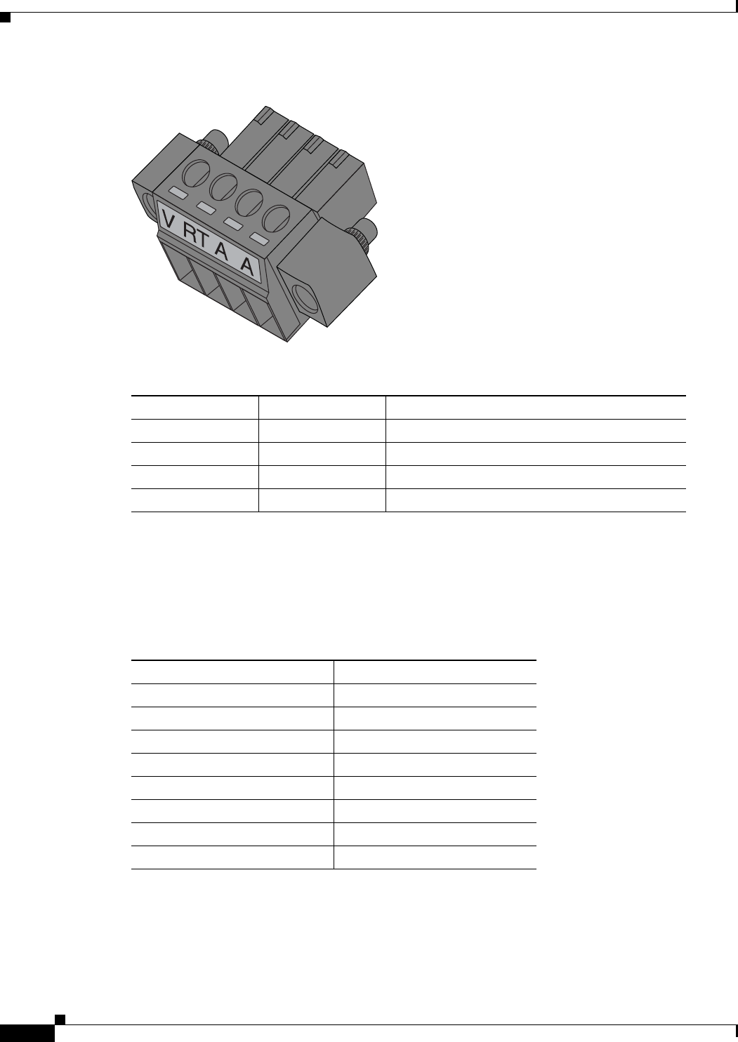
29/OCT/2014 REVIEW DRAFT — CISCO CONFIDENTIAL
B-2
Cisco IR500 Series WPAN Gateway and Range Extender Installation and Configuration Guide
Appendix B Cable and Connectors
Connector Specifications
Figure B-1 WPAN Gateway Power and Alarm Connector
391216
Table B-1 WPAN Gateway Power and Alarm Connector Pinouts
Pin Label Signal Description
1 V Positive DC power connection
2RT Return DC power connection
3 A Alarm reference or Alarm in
4 A Alarm reference or Alarm in
WPAN Gateway Console Port
The console port on the WPAN gateway uses an RJ-45 connector. The console port is an RS232 serial
port. Table B-7 describes the pinouts.
Table B-2 WPAN Gateway Console Port Pinouts
Pin Signal
1RTS output
2DTR input
3TxD output
4GND
5GND
6RxD input
7DSR output
8CTS input
WPAN Gateway RS232/RS485 DCE Serial Port
The WPAN Gateway RS232/RS485 serial port uses an RJ45 connector. Table B-3 shows the pinouts,
depending on whether the user selects RS232 or RS485.

Table B-3 WPAN Gateway RS232/RS485 DCE Serial Port Pinouts
Pin RS232 Signal (Full Duplex) RS485 Signal (Full Duplex) RS485 (Half Duplex)
1DSR/RI—Data Set Ready/Ring
Indicator (out) TX+ (out) TX/RX+ (in/out)
2DCD—Data Carrier Detect (out) TX- (out) TX/RX- (in/out)
3DTR—Data Terminal Ready (in) RX- (in) Not used
4SGND—Signal Ground COM COM
5RxD—Receive Data (out) Not used Not used
6TxD—Transmit Data (in) RX+ (in) Not used
7CTS—Clear to Send (out) Not used Not used
8RTS—Request to Send (in) Not used Not used
29/OCT/2014 REVIEW DRAFT — CISCO CONFIDENTIAL
B-3
Cisco IR500 Series WPAN Gateway and Range Extender Installation and Configuration Guide
Appendix B Cable and Connectors Connector Specifications
WPAN Gateway RS232 DTE Serial Port
The WPAN gateway RS232 DTE serial port uses and RJ-45 connector. Table B-4 describes the pinouts.
Table B-4 WPAN Gateway RS232 DCE Port Pinouts
Pin Signal
1DSR (in)
2DCD (in)
3DTR (out)
4SGND
5RXD (in)
6TXD (out)
7CTS (in)
8RTS (out)
WPAN Gateway USB Port
The WPAN gateway USB port uses a Standard A connector. Table B-5 describes the pinouts.
Table B-5 WPAN Gateway USB Port Pinouts
Pin Name Description
1 V +5 VDC
2D- Data-
3D+ Data+
4GND Ground
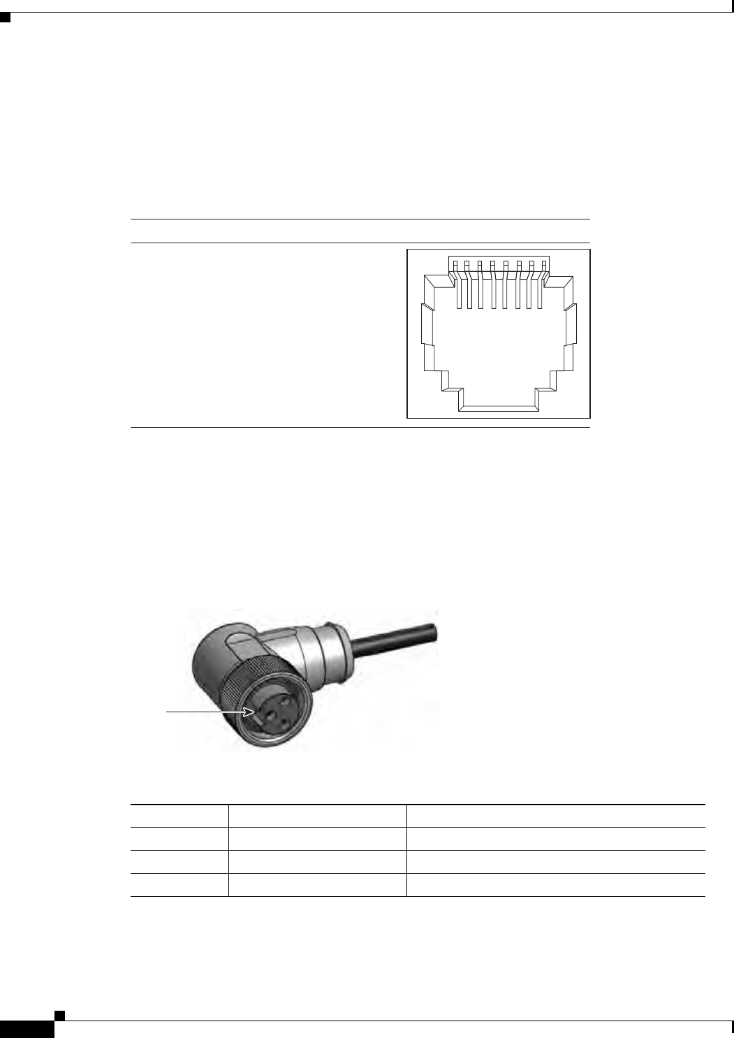
29/OCT/2014 REVIEW DRAFT — CISCO CONFIDENTIAL
B-4
Cisco IR500 Series WPAN Gateway and Range Extender Installation and Configuration Guide
Appendix B Cable and Connectors
Connector Specifications
WPAN Gateway 10/100 Fast Ethernet Port
The 10/100 Fast Ethernet port uses an RJ-45 connector. Figure B-2 shows the pinouts. This port supports
Auto-MDIX (Automatic TX/RX crossover) and Auto-Polarity (Auto +/- polarity detection and
correction).
Figure B-2 WPAN Gateway 10/100 Fast Ethernet Port Pinouts
391949
231 45678Pin Label
1
2
3
4
5
6
7
8
RD-
RD+
TD-
NC
NC
TD+
NC
NC
WPAN Range Extender Power Connector
Figure B-3 shows the WPAN range extender 3 pin power connector. The pinouts are described in
Table B-6.
Figure B-3 WPAN Range Extender Power Connector
300595
Notch
Table B-6 WPAN Range Extender Power Connector Pinouts
Pin Signal Name Signal Description
1 L AC line
2 N AC neutral
3Chassis Chassis ground

29/OCT/2014 REVIEW DRAFT — CISCO CONFIDENTIAL
B-5
Cisco IR500 Series WPAN Gateway and Range Extender Installation and Configuration Guide
Appendix B Cable and Connectors Cables and Adapters
WPAN Range Extender Console Port
The console port on the WPAN range extender uses and RJ-45 connector. The console port is an RS232
serial port. Table B-7 describes the pinouts.
Table B-7 WPAN Range Extender Console Port Pinouts
Pin Signal
1RTS
2DTR
3TxD
4GND
5GND
6RxD
7DSR
8CTS
Cables and Adapters
• WPAN Gateway and WPAN Range Extender Console Port Adapter Pinouts, page B-5
WPAN Gateway and WPAN Range Extender Console Port Adapter Pinouts
The console port uses an 8-pin RJ-45 connector. If you did not order a console cable, you need to provide
an RJ-45-to-DB-9 adapter cable to connect the console port to a PC console port. You can order an
adapter (part number ACS-DSBUASYN=).
Table B-8 lists the pinouts for the console port, the RJ-45-to-DB-9 adapter cable, and the console device.
Table B-8 Console Port Signaling Using a DB-9 Adapter
Device Console
Port (DTE) RJ-45-to-DB-9
Terminal Adapter Console
Device
Signal DB-9 Pin Signal
RTS 8CTS
DTR 6DSR
TxD 2RxD
GND 5GND
RxD 3TxD
DSR 4DTR
CTS 7RTS

29/OCT/2014 REVIEW DRAFT — CISCO CONFIDENTIAL
B-6
Cisco IR500 Series WPAN Gateway and Range Extender Installation and Configuration Guide
Appendix B Cable and Connectors
Cables and Adapters