Cisco Systems IR529UWP IR529 915Mhz WPAN IP67 Range Extender User Manual
Cisco Systems Inc IR529 915Mhz WPAN IP67 Range Extender
UserManual.wiki
>
Cisco Systems
>
IR529UWP User Manual
>
Users Manual 4
Contents
1.
Users Manual
2.
Users manual 2
3.
Users Manual 3
4.
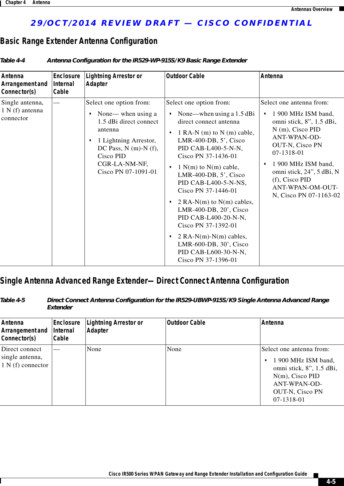
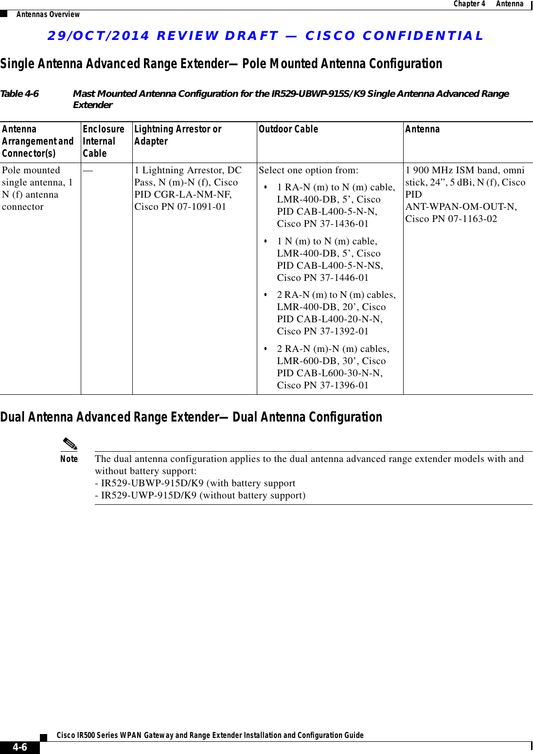
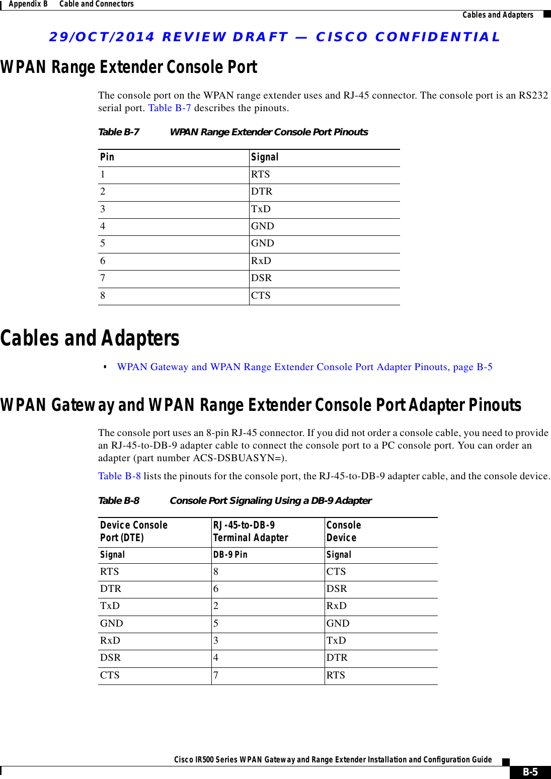
Users Manual 4
Users Manual 4
Navigation menu
Upload a User Manual
Namespaces
Wiki Guide
HTML
PDF
Info
Views
User Manual
Discussion / Help
Navigation