Cisco Systems TG2050 802.11 a/b/g/n AP Module User Manual Host System configuration guide
Cisco Systems Inc 802.11 a/b/g/n AP Module Host System configuration guide
Contents
- 1. Host System configuration guide
- 2. Host system manual
- 3. Installation Guide
- 4. Host system literature
- 5. Host manual part 1
- 6. Host manual part 2
Host System configuration guide


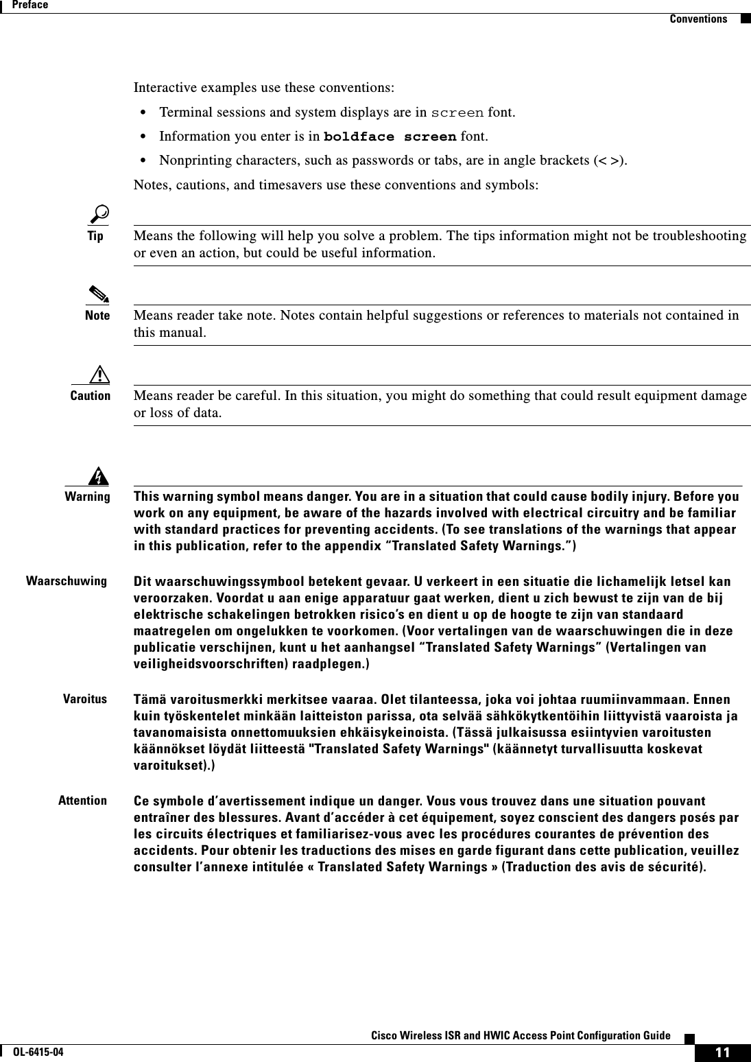
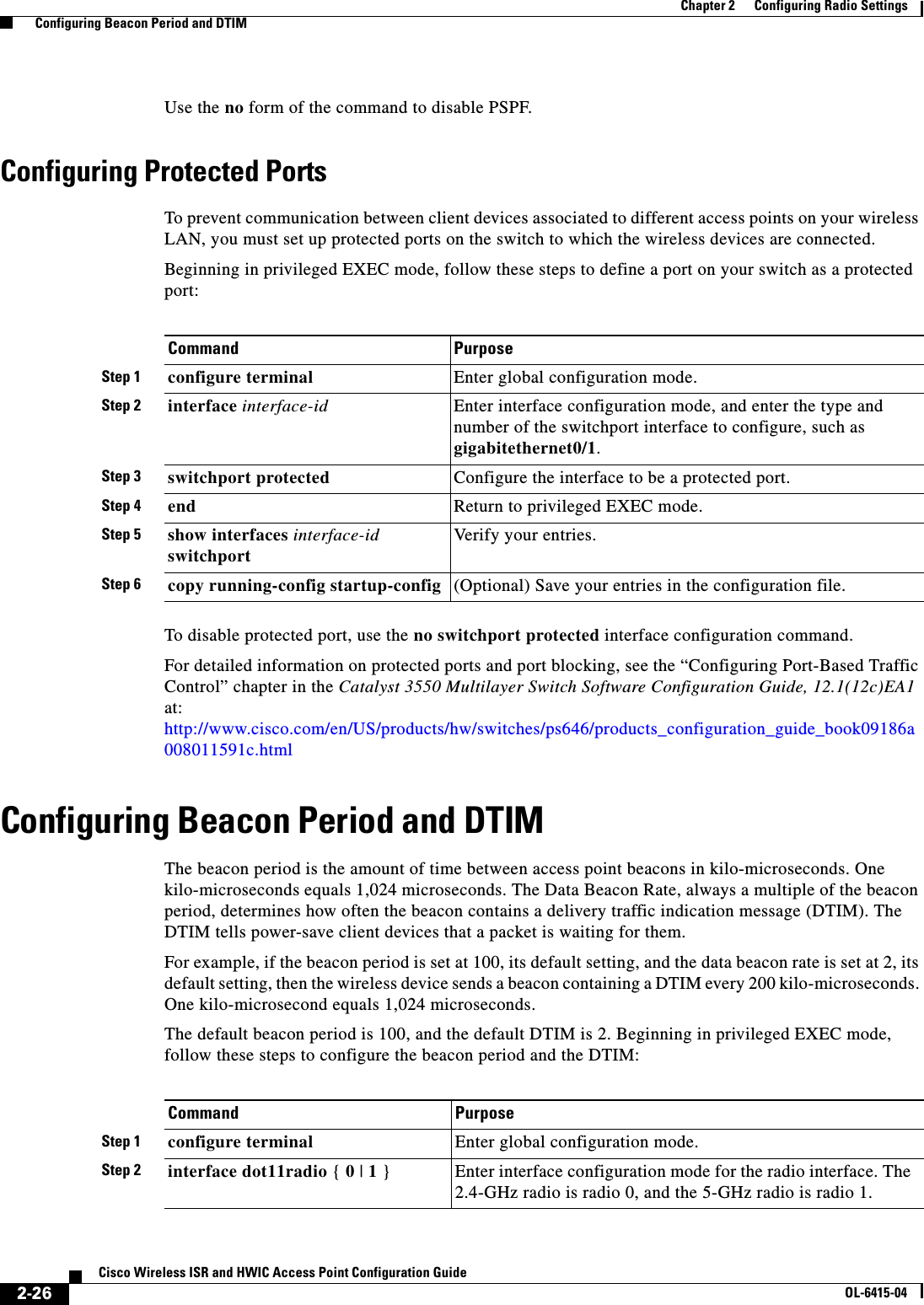
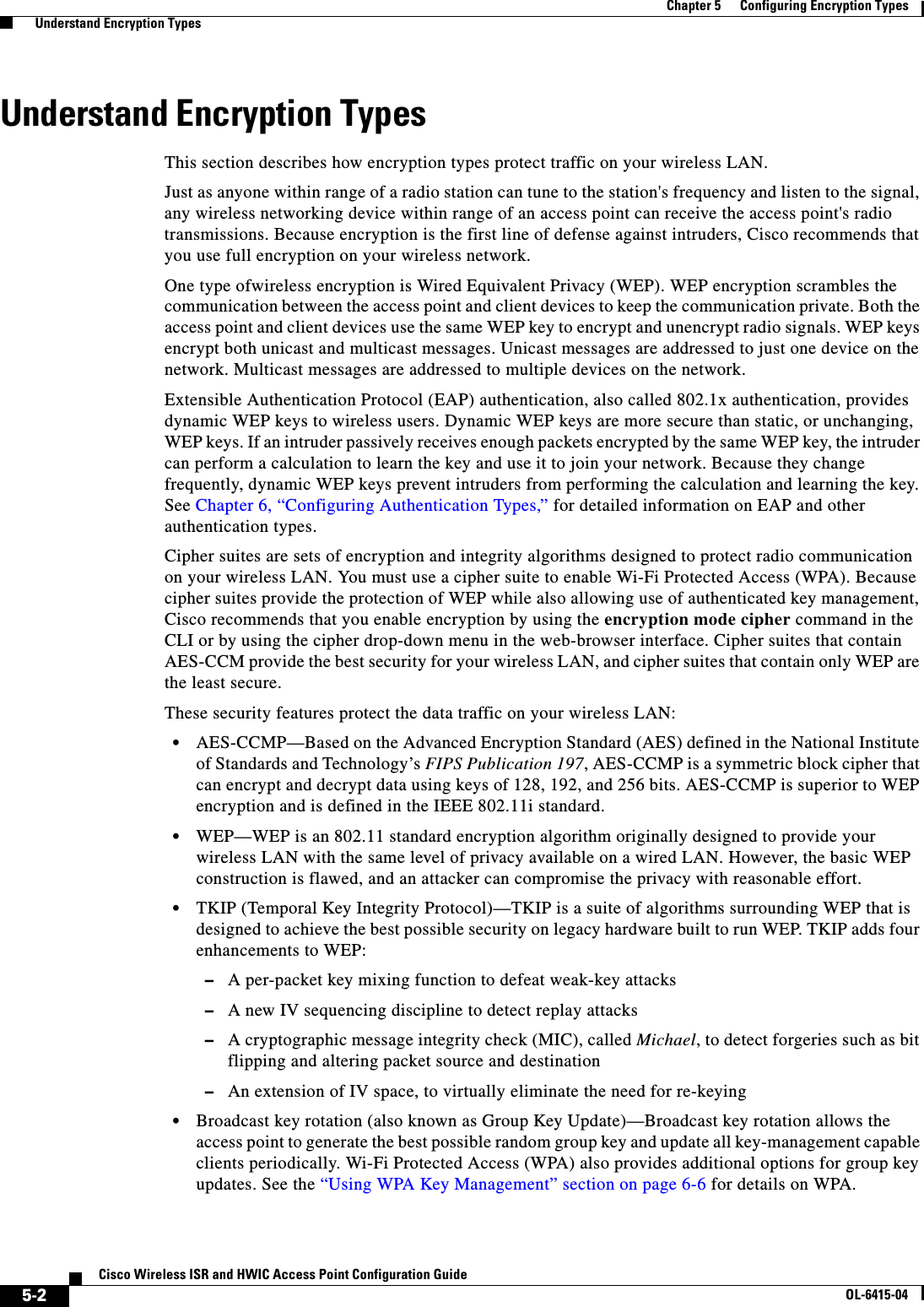
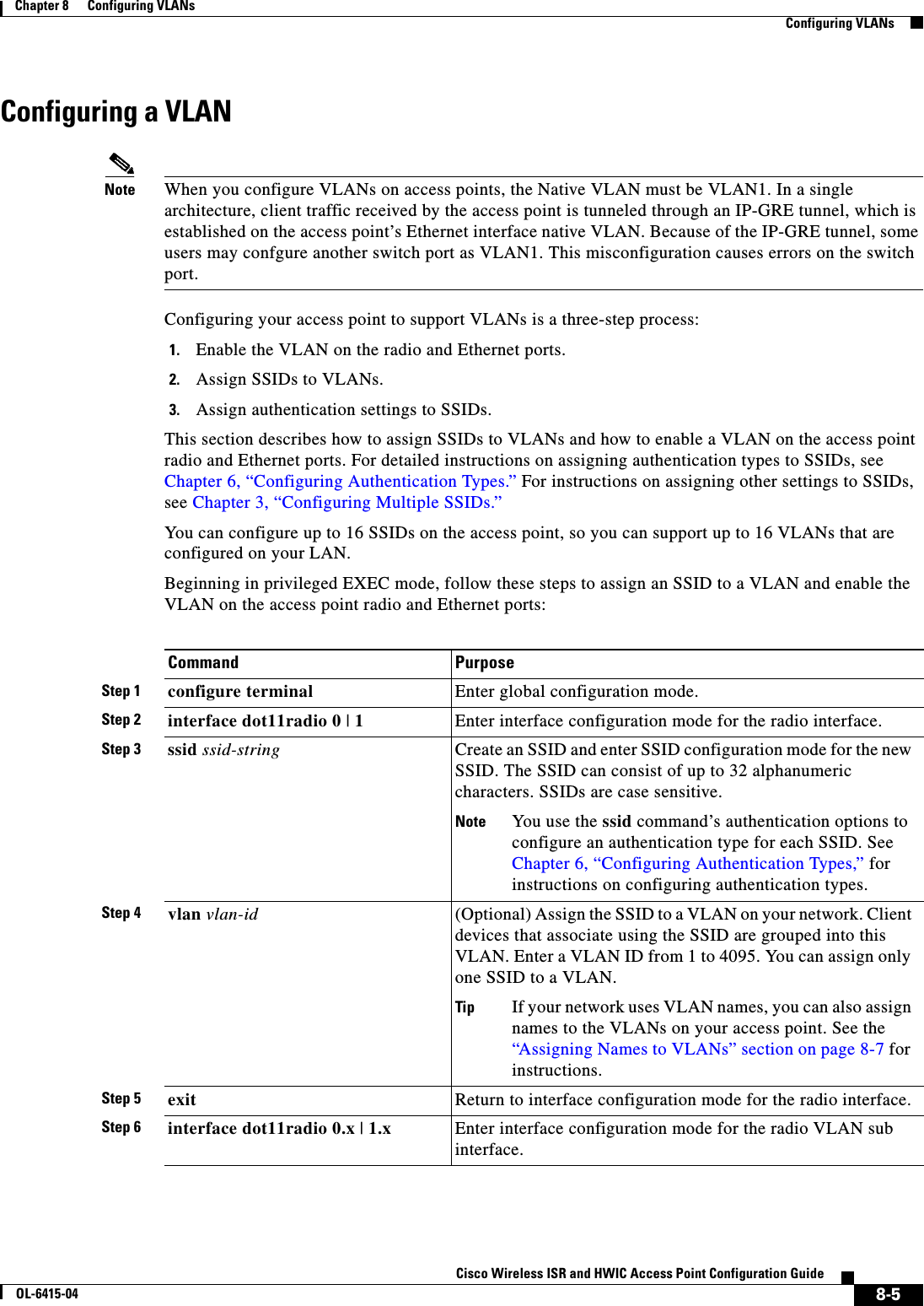
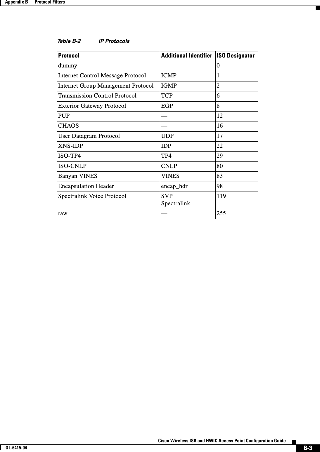
![10Cisco Wireless ISR and HWIC Access Point Configuration GuideOL-6415-04PrefaceOrganizationOrganizationThis guide consists of the following chapters:Chapter 1, “Overview,” lists the software and hardware features of the wireless device and describes the role of the wireless device in your network.Chapter 2, “Configuring Radio Settings,” describes how to configure settings for the wireless device radio such as the role in the radio network, data rates, transmit power, channel settings, and others.Chapter 3, “Configuring Multiple SSIDs,” describes how to configure and manage multiple service set identifiers (SSIDs) and multiple basic SSIDs (BSSIDs) on your wireless device. You can configure up to 16 SSIDs and 16 BSSIDs on your wireless device and assign different configuration settings to each.Chapter 4, “Configuring an Access Point as a Local Authenticator,” describes how to configure the wireless device to act as a local RADIUS server for your wireless LAN. If the WAN connection to your main RADIUS server fails, the wireless device acts as a backup server to authenticate wireless devices.Chapter 5, “Configuring Encryption Types,” describes how to configure the cipher suites required to use authenticated key management, Wired Equivalent Privacy (WEP), and WEP features.Chapter 6, “Configuring Authentication Types,” describes how to configure authentication types on the wireless device. Client devices use these authentication methods to join your network.Chapter 7, “Configuring RADIUS Servers,” describes how to enable and configure the RADIUS, which provides detailed accounting information and flexible administrative control over authentication and authorization processes. Chapter 8, “Configuring VLANs,” describes how to configure your wireless device to interoperate with the VLANs set up on your wired LAN. Chapter 9, “Configuring QoS,” describes how to configure quality of service (QoS) on your wireless device. With this feature, you can provide preferential treatment to certain traffic at the expense of others.Appendix A, “Channel Settings,” lists the wireless device radio channels and the maximum power levels supported by the world’s regulatory domains.Appendix B, “Protocol Filters,” lists some of the protocols that you can filter on the wireless device. Appendix C, “Supported MIBs,” lists the Simple Network Management Protocol (SNMP) Management Information Bases (MIBs) that the wireless device supports for this software release.Appendix D, “Error and Event Messages,” lists the CLI error and event messages and provides an explanation and recommended action for each message.ConventionsThis publication uses these conventions to convey instructions and information:Command descriptions use these conventions: • Commands and keywords are in boldface text. • Arguments for which you supply values are in italic. • Square brackets ([ ]) mean optional elements. • Braces ({ }) group required choices, and vertical bars ( | ) separate the alternative elements. • Braces and vertical bars within square brackets ([{ | }]) mean a required choice within an optional element.](https://usermanual.wiki/Cisco-Systems/TG2050.Host-System-configuration-guide/User-Guide-1779203-Page-10.png)
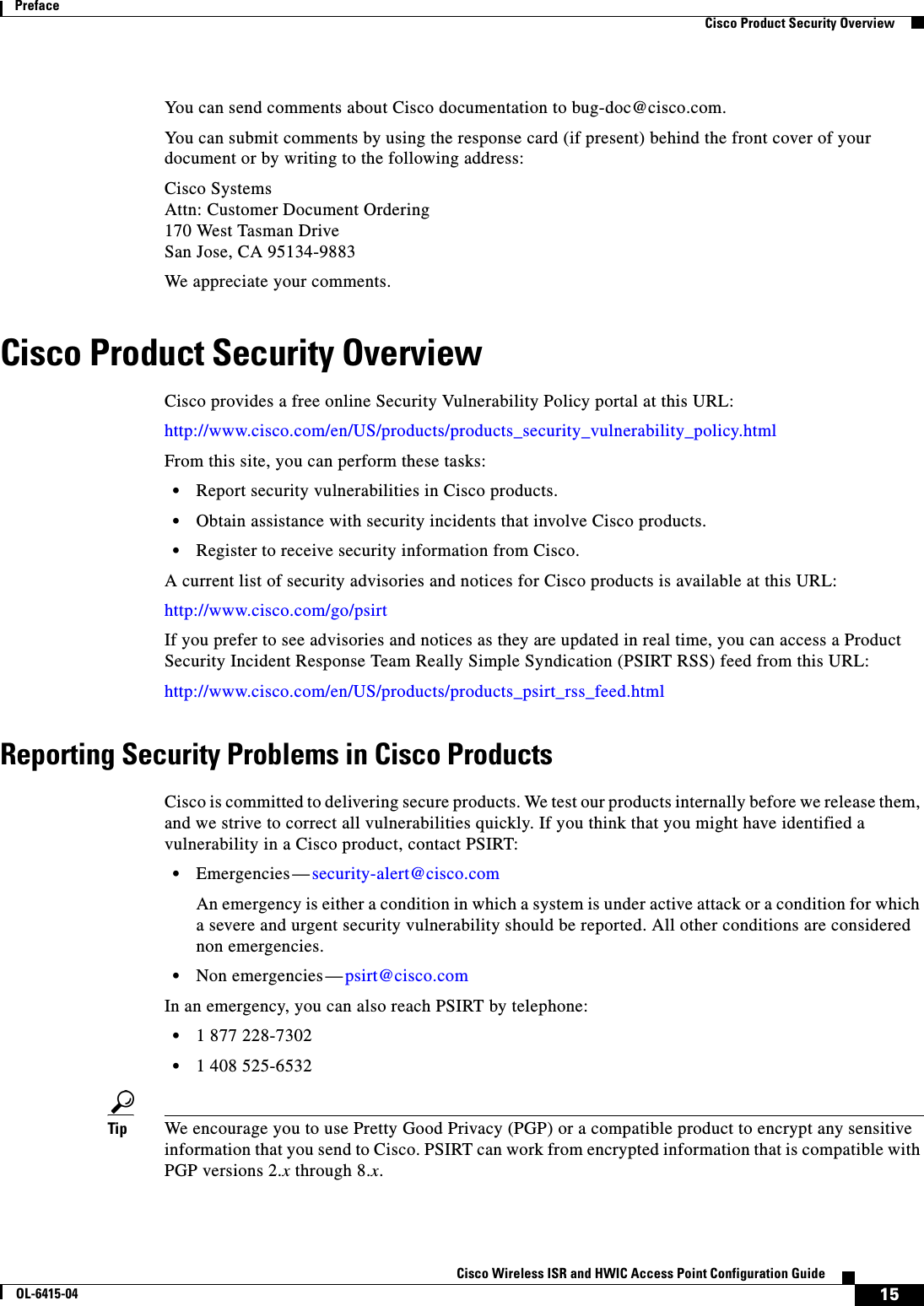
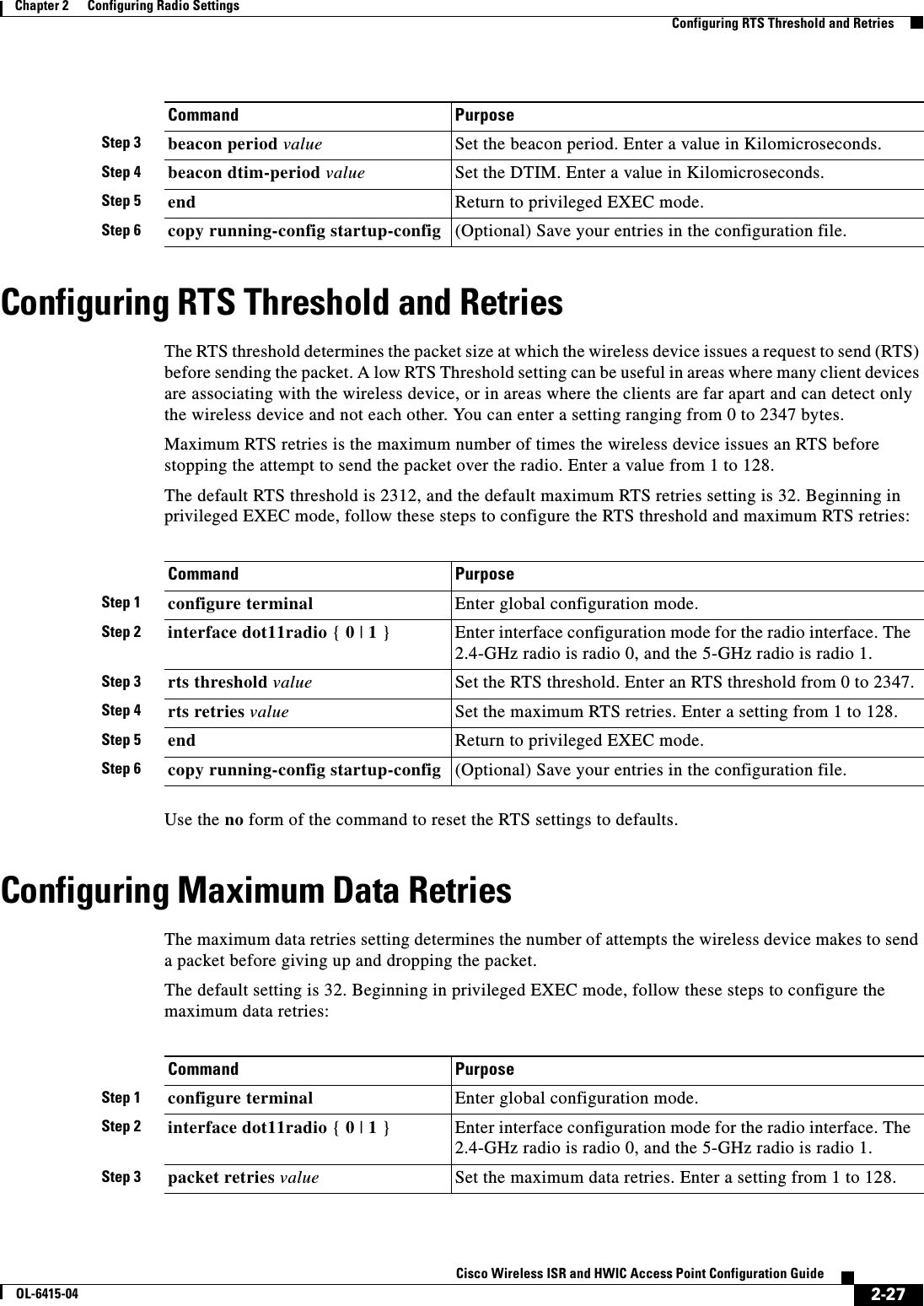
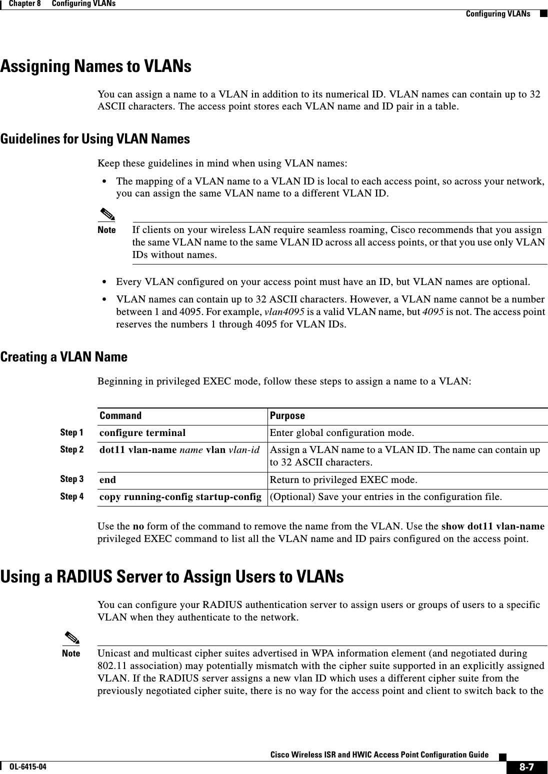
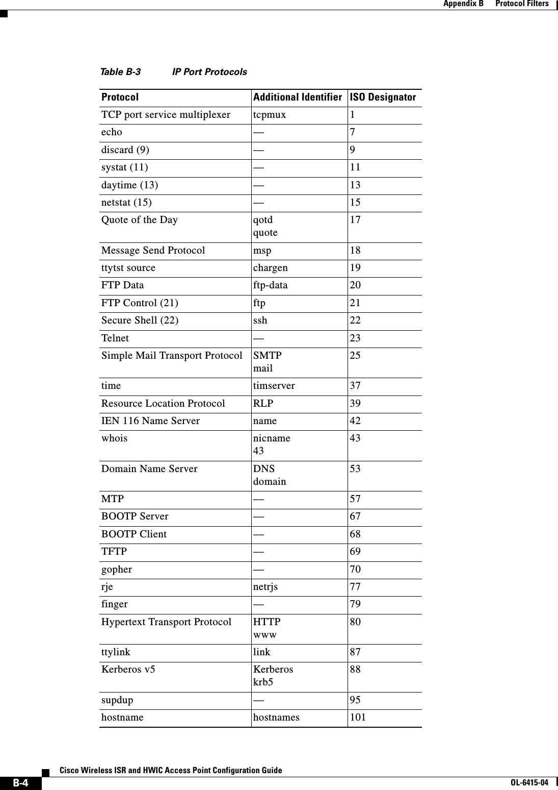
![12Cisco Wireless ISR and HWIC Access Point Configuration GuideOL-6415-04PrefaceRelated PublicationsRelated PublicationsRelated Cisco technical documentation include the following:WarnungDieses Warnsymbol bedeutet Gefahr. Sie befinden sich in einer Situation, die zu einer Körperverletzung führen könnte. Bevor Sie mit der Arbeit an irgendeinem Gerät beginnen, seien Sie sich der mit elektrischen Stromkreisen verbundenen Gefahren und der Standardpraktiken zur Vermeidung von Unfällen bewußt. (Übersetzungen der in dieser Veröffentlichung enthaltenen Warnhinweise finden Sie im Anhang mit dem Titel “Translated Safety Warnings” (Übersetzung der Warnhinweise).)AvvertenzaQuesto simbolo di avvertenza indica un pericolo. Si è in una situazione che può causare infortuni. Prima di lavorare su qualsiasi apparecchiatura, occorre conoscere i pericoli relativi ai circuiti elettrici ed essere al corrente delle pratiche standard per la prevenzione di incidenti. La traduzione delle avvertenze riportate in questa pubblicazione si trova nell’appendice, “Translated Safety Warnings” (Traduzione delle avvertenze di sicurezza).AdvarselDette varselsymbolet betyr fare. Du befinner deg i en situasjon som kan føre til personskade. Før du utfører arbeid på utstyr, må du være oppmerksom på de faremomentene som elektriske kretser innebærer, samt gjøre deg kjent med vanlig praksis når det gjelder å unngå ulykker. (Hvis du vil se oversettelser av de advarslene som finnes i denne publikasjonen, kan du se i vedlegget "Translated Safety Warnings" [Oversatte sikkerhetsadvarsler].)AvisoEste símbolo de aviso indica perigo. Encontra-se numa situação que lhe poderá causar danos fisicos. Antes de começar a trabalhar com qualquer equipamento, familiarize-se com os perigos relacionados com circuitos eléctricos, e com quaisquer práticas comuns que possam prevenir possíveis acidentes. (Para ver as traduções dos avisos que constam desta publicação, consulte o apêndice “Translated Safety Warnings” - “Traduções dos Avisos de Segurança”).¡Advertencia!Este símbolo de aviso significa peligro. Existe riesgo para su integridad física. Antes de manipular cualquier equipo, considerar los riesgos que entraña la corriente eléctrica y familiarizarse con los procedimientos estándar de prevención de accidentes. (Para ver traducciones de las advertencias que aparecen en esta publicación, consultar el apéndice titulado “Translated Safety Warnings.”)Varning!Denna varningssymbol signalerar fara. Du befinner dig i en situation som kan leda till personskada. Innan du utför arbete på någon utrustning måste du vara medveten om farorna med elkretsar och känna till vanligt förfarande för att förebygga skador. (Se förklaringar av de varningar som förekommer i denna publikation i appendix "Translated Safety Warnings" [Översatta säkerhetsvarningar].)Ta b l e 1Related and Referenced Documents Cisco Product Document TitleCisco Access Point High-Speed WAN Interface CardCisco Interface Cards Installation GuideQuick Start Guide: Interface Cards for Cisco Access RoutersInstalling, Replacing, and Upgrading Components in Cisco Modular Access Routers and Integrated Services Routers](https://usermanual.wiki/Cisco-Systems/TG2050.Host-System-configuration-guide/User-Guide-1779203-Page-12.png)
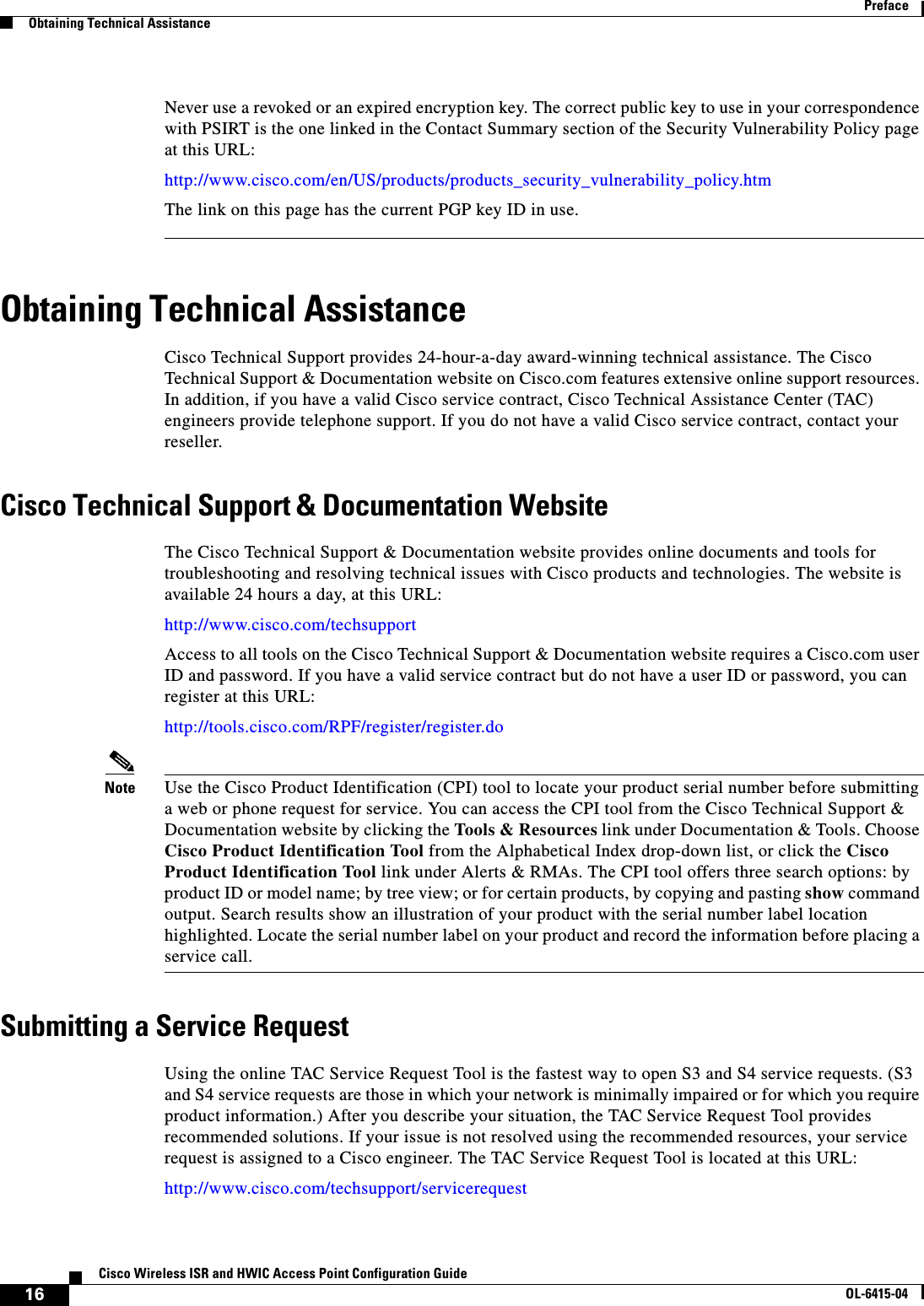

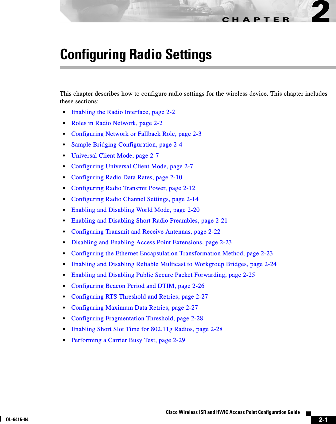
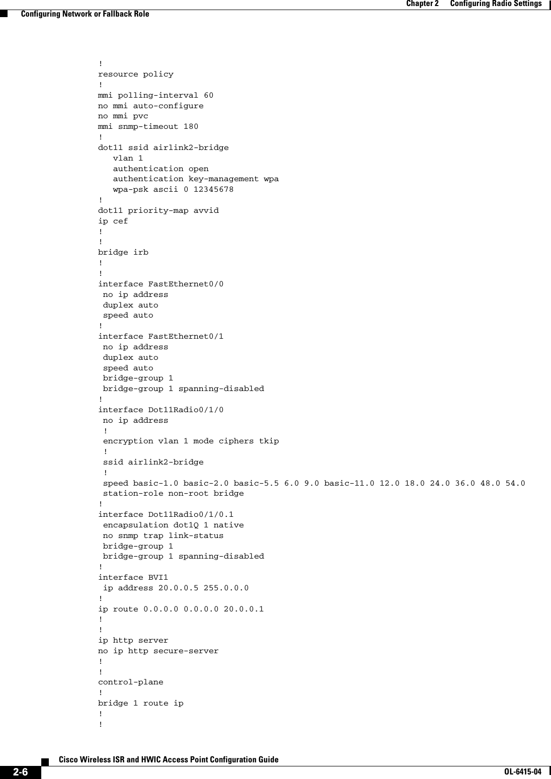
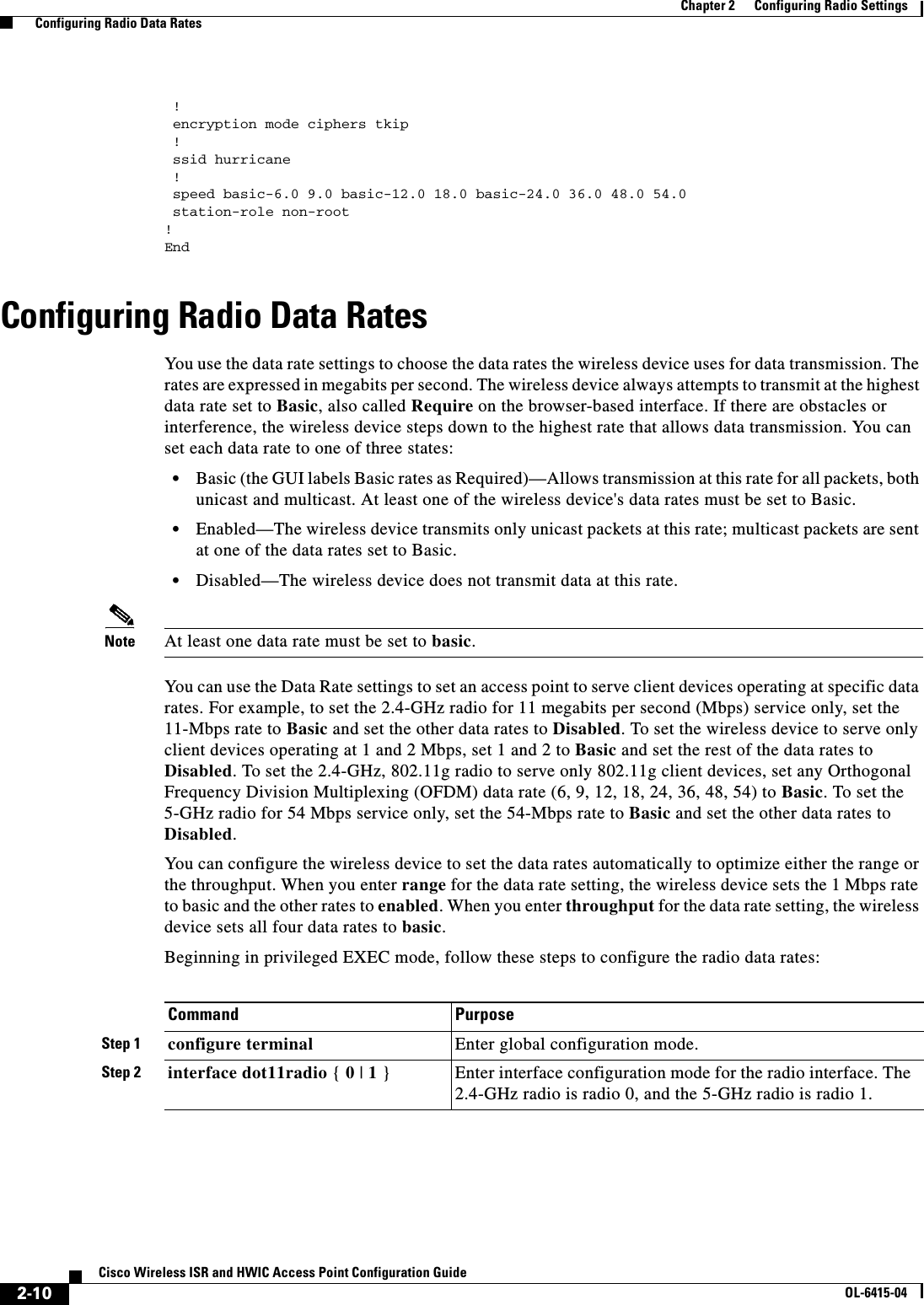
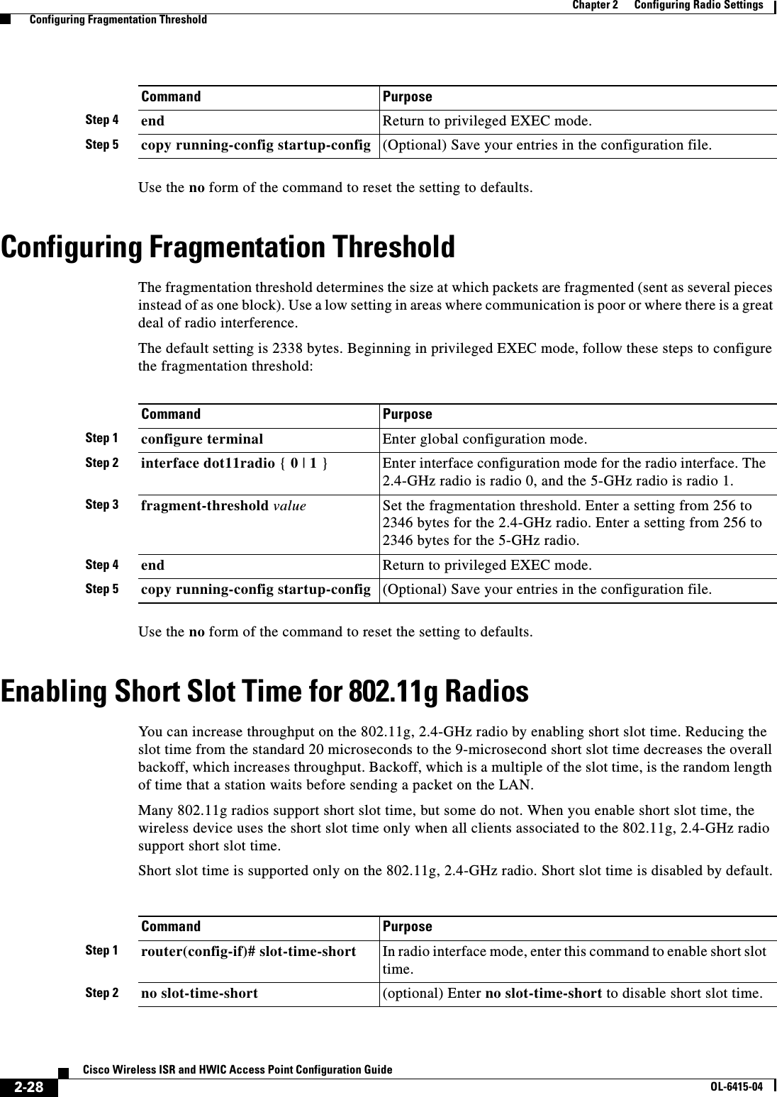
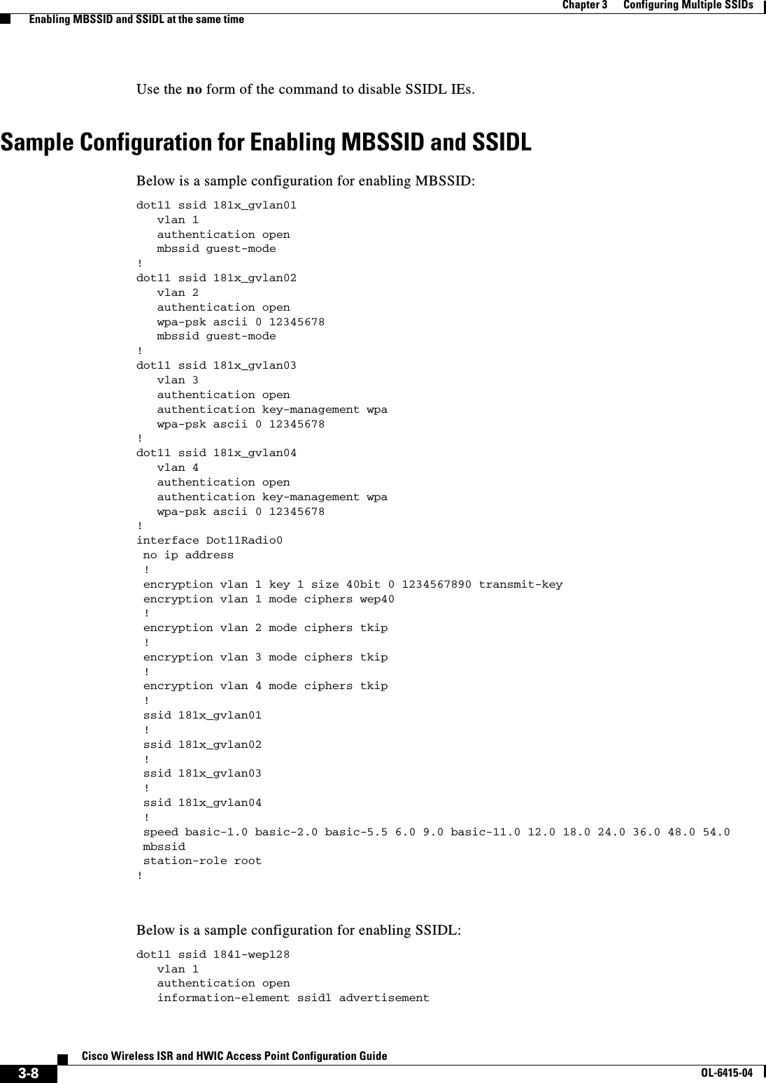
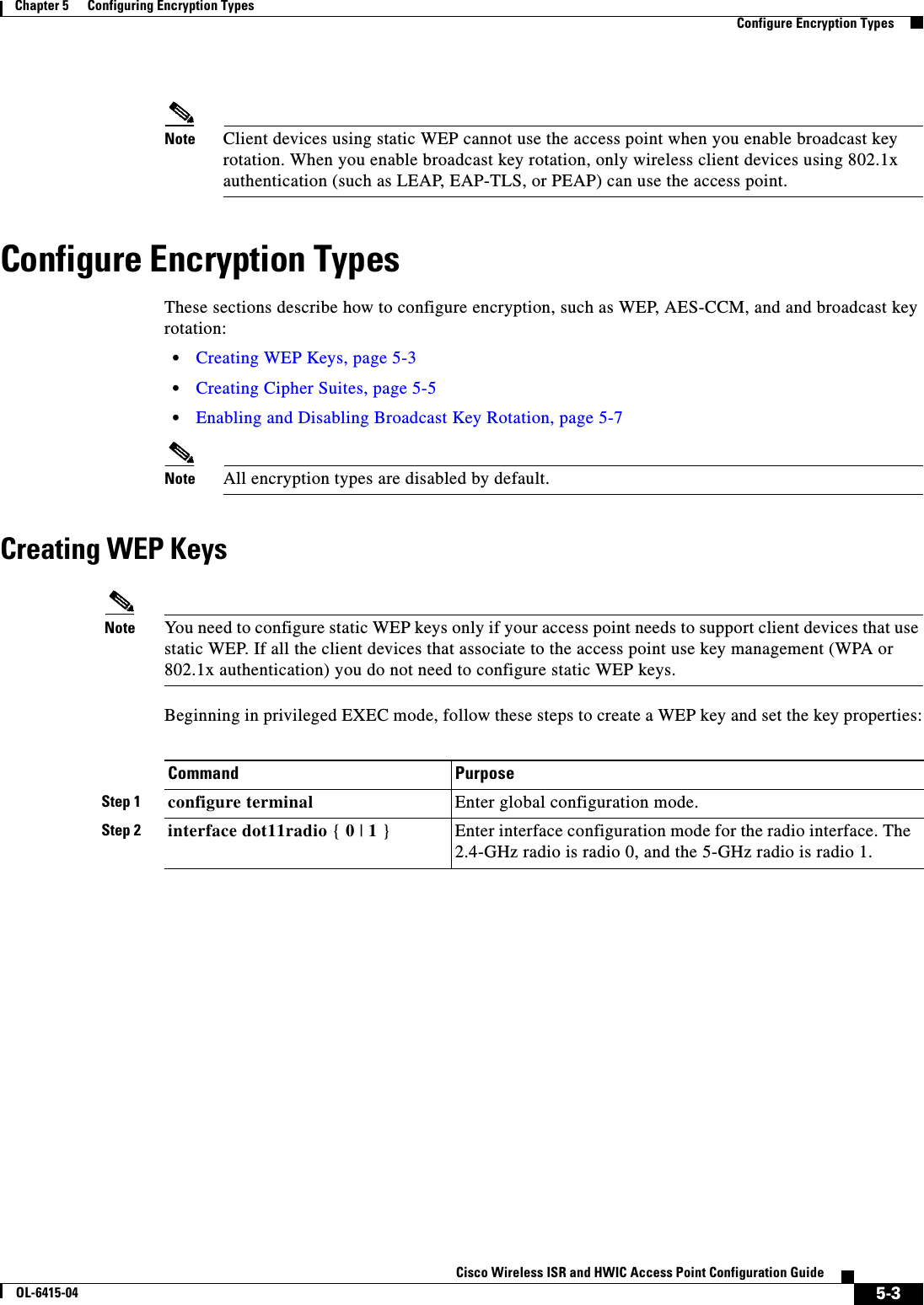
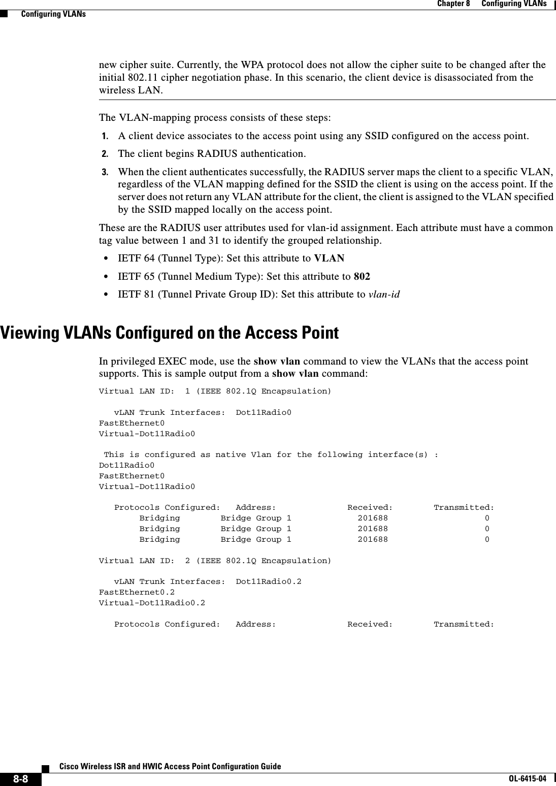
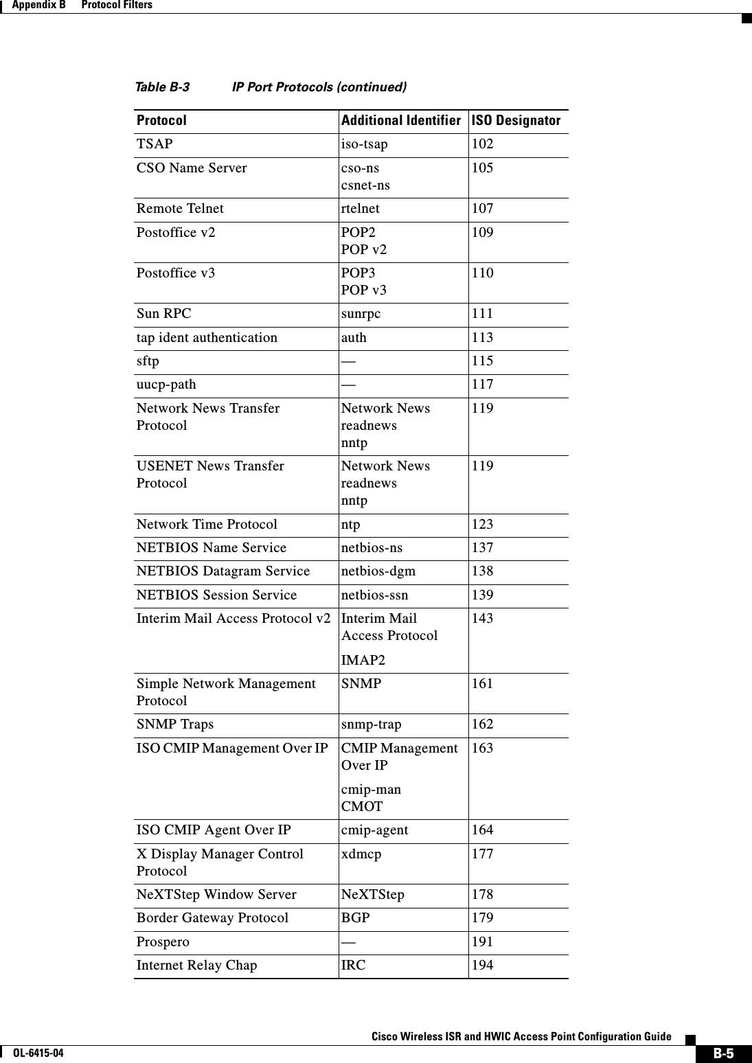
![2-3Cisco Wireless ISR and HWIC Access Point Configuration GuideOL-6415-04Chapter 2 Configuring Radio Settings Configuring Network or Fallback RoleConfiguring Network or Fallback RoleYou can also configure a fallback role for root access points. The wireless device automatically assumes the fallback role when its Ethernet port is disabled or disconnected from the wired LAN. Thefallback role is Shutdown—the wireless device shuts down its radio and disassociates all client devices.Beginning in privileged EXEC mode, follow these steps to set the wireless device’s radio network role and fallback role:Command PurposeStep 1 configure terminal Enter global configuration mode.Step 2 interface dot11radio { 0 | 1 }Enter interface configuration mode for the radio interface. The 2.4-GHz radio is radio 0, and the 5-GHz radio is radio 1.Step 3 station-role non-root {bridge | return} root {fallback | repeater | wireless clients | shutdown]} Sets the wireless device role to universal client mode. • Set the role to non-root bridge with or without wireless clients, repeater access point, root access point or bridge, scanner, or workgroup bridge. • The bridge mode radio supports point-to-point configuration only. • The Ethernet port is shut down when any one of the radios is configured as a repeater. Only one radio per access point may be configured as a workgroup bridge or repeater. • The dot11radio 0|1 antenna-alignment command is available when the access point is configured as a repeater. • Spanning Tree Protocol (STP) is configurable on Cisco ISR series access points in bridge modes. • (Optional) Select the root access point’s fallback role. If the wireless device’s Ethernet port is disabled or disconnected from the wired LAN, the wireless device can either shut down its radio port or become a repeater access point associated to any nearby root access point.Step 4 end Return to privileged EXEC mode.Step 5 copy running-config startup-config (Optional) Save your entries in the configuration file.](https://usermanual.wiki/Cisco-Systems/TG2050.Host-System-configuration-guide/User-Guide-1779203-Page-27.png)
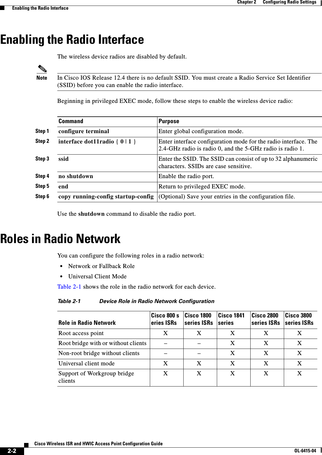
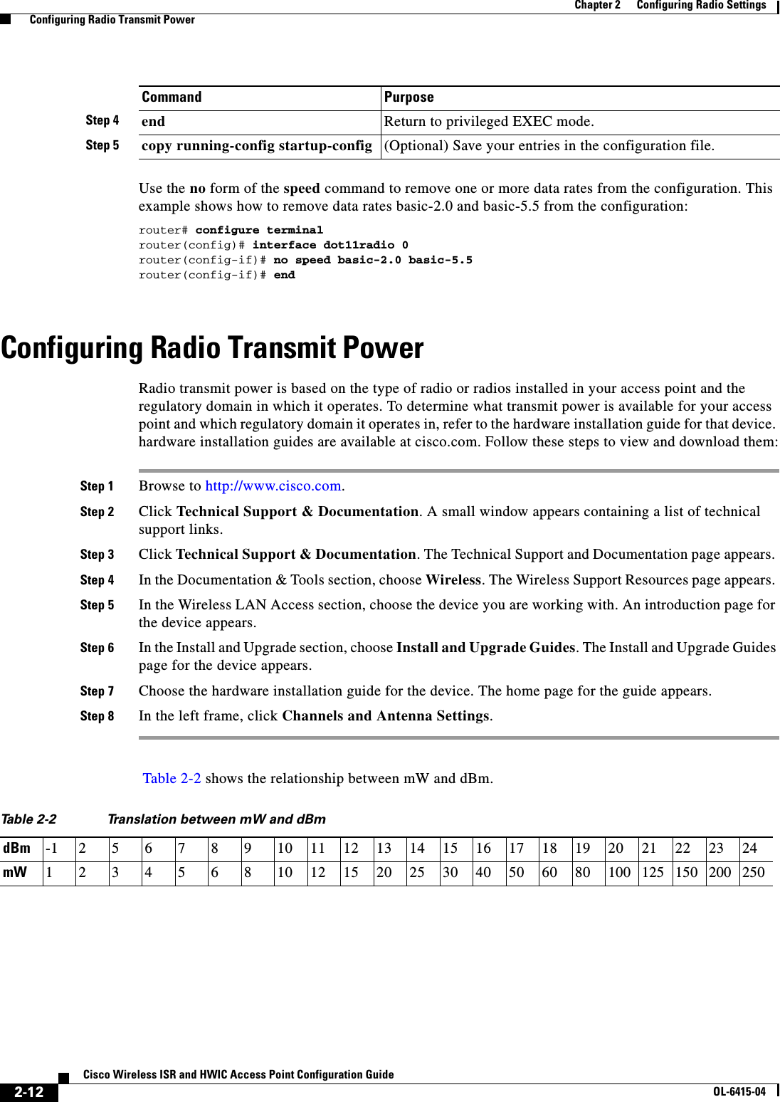
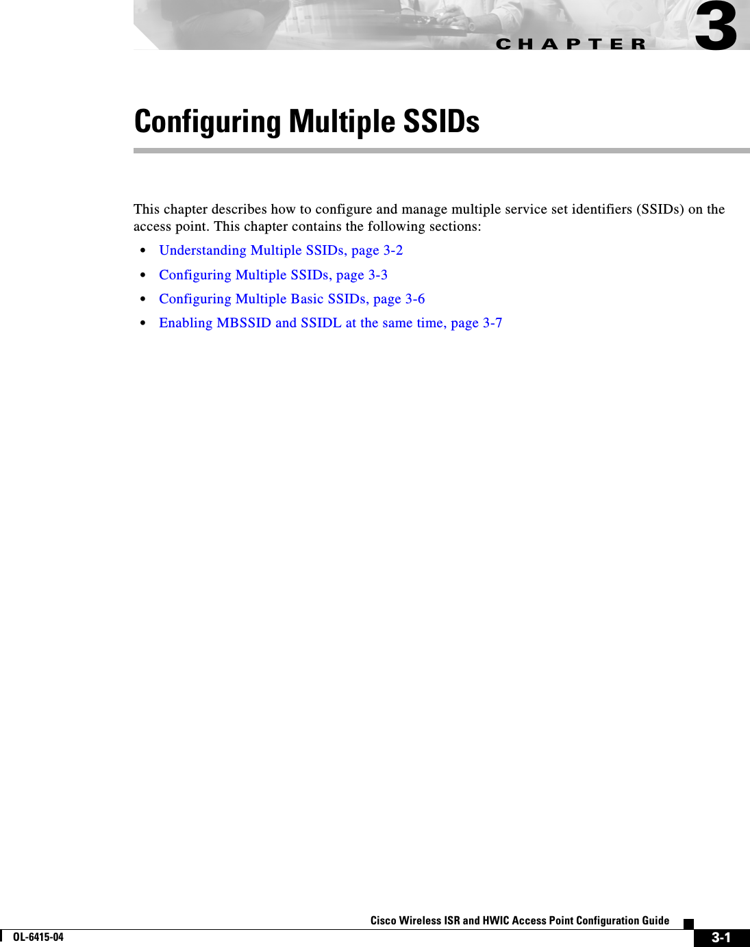
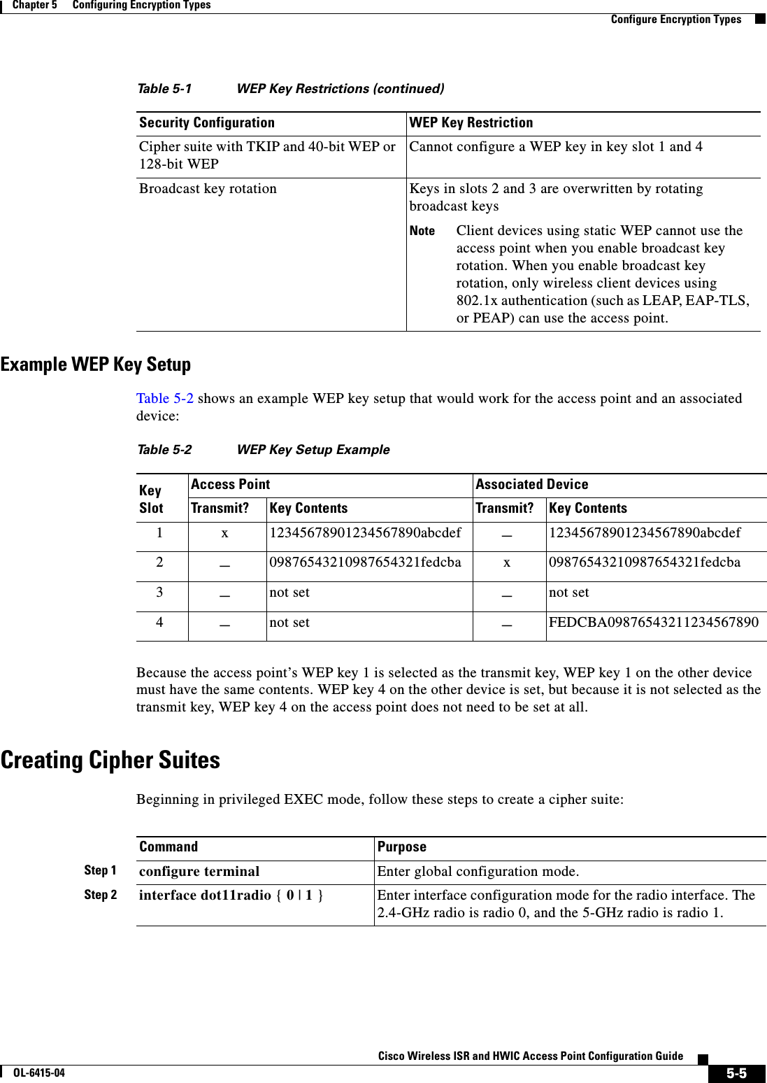
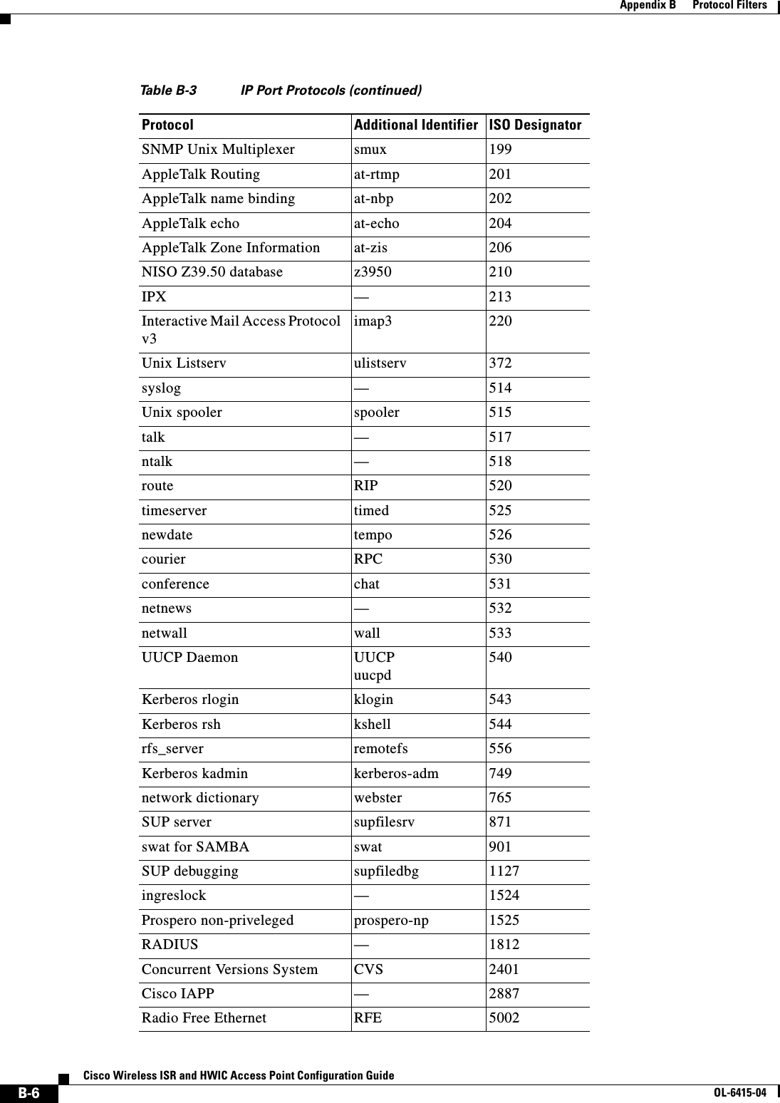
![2-11Cisco Wireless ISR and HWIC Access Point Configuration GuideOL-6415-04Chapter 2 Configuring Radio Settings Configuring Radio Data RatesStep 3 speedThese options are available for the 802.11b, 2.4-GHz radio:{[1.0] [11.0] [2.0] [5.5] [basic-1.0] [basic-11.0] [basic-2.0] [basic-5.5] | range | throughput}These options are available for the 802.11g, 2.4-GHz radio:{[1.0] [2.0] [5.5] [6.0] [9.0] [11.0] [12.0] [18.0] [24.0] [36.0] [48.0] [54.0] [basic-1.0] [basic-2.0] [basic-5.5] [basic-6.0] [basic-9.0] [basic-11.0] [basic-12.0] [basic-18.0] [basic-24.0] [basic-36.0] [basic-48.0] [basic-54.0] | range | throughput [ofdm] | default }These options are available for the 5-GHz radio:{[6.0] [9.0] [12.0] [18.0] [24.0] [36.0] [48.0] [54.0] [basic-6.0] [basic-9.0] [basic-12.0] [basic-18.0] [basic-24.0] [basic-36.0] [basic-48.0] [basic-54.0] | range | throughput |default }Set each data rate to basic or enabled, or enter range to optimize range or throughput to optimize throughput. • (Optional) Enter 1.0, 2.0, 5.5, and 11.0 to set these data rates to enabled on the 802.11b, 2.4-GHz radio. Enter 1.0, 2.0, 5.5, 6.0, 9.0, 11.0, 12.0, 18.0, 24.0, 36.0, 48.0, and 54.0 to set these data rates to enabled on the 802.11g, 2.4-GHz radio. Enter 6.0, 9.0, 12.0, 18.0, 24.0, 36.0, 48.0, and 54.0 to set these data rates to enabled on the 5-GHz radio. • (Optional) Enter basic-1.0, basic-2.0, basic-5.5, and basic-11.0 to set these data rates to basic on the 802.11b, 2.4-GHz radio.Enter basic-1.0, basic-2.0, basic-5.5, basic-6.0, basic-9.0, basic-11.0, basic-12.0, basic-18.0, basic-24.0, basic-36.0, basic-48.0, and basic-54.0 to set these data rates to basic on the 802.11g, 2.4-GHz radio. Note The client must support the basic rate that you select or it cannot associate to the wireless device. If you select 12 Mbps or higher for the basic data rate on the 802.11g radio, 802.11b client devices cannot associate to the wireless device’s 802.11g radio.Enter basic-6.0, basic-9.0, basic-12.0, basic-18.0, basic-24.0, basic-36.0, basic-48.0, and basic-54.0 to set these data rates to basic on the 5-GHz radio. • (Optional) Enter range or throughput to automatically optimize radio range or throughput. When you enter range, the wireless device sets the lowest data rate to basic and the other rates to enabled. When you enter throughput, the wireless device sets all data rates to basic. (Optional) On the 802.11g radio, enter speed throughput ofdm to set all OFDM rates (6, 9, 12, 18, 24, 36, and 48) to basic (required) and set all the CCK rates (1, 2, 5.5, and 11) to disabled. This setting disables 802.11b protection mechanisms and provides maximum throughput for 802.11g clients. However, it prevents 802.11b clients from associating to the access point. • (Optional) Enter default to set the data rates to factory default settings (not supported on 802.11b radios).On the 802.11g radio, the default option sets rates 1, 2, 5.5, and 11 to basic, and rates 6, 9, 12, 18, 24, 36, 48, and 54 to enabled. These rate settings allow both 802.11b and 802.11g client devices to associate to the wireless device’s 802.11g radio.On the 5-GHz radio, the default option sets rates 6.0, 12.0, and 24.0 to basic, and rates 9.0, 18.0, 36.0, 48.0, and 54.0 to enabled.Command Purpose](https://usermanual.wiki/Cisco-Systems/TG2050.Host-System-configuration-guide/User-Guide-1779203-Page-35.png)
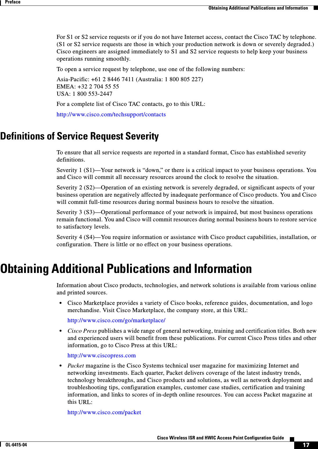
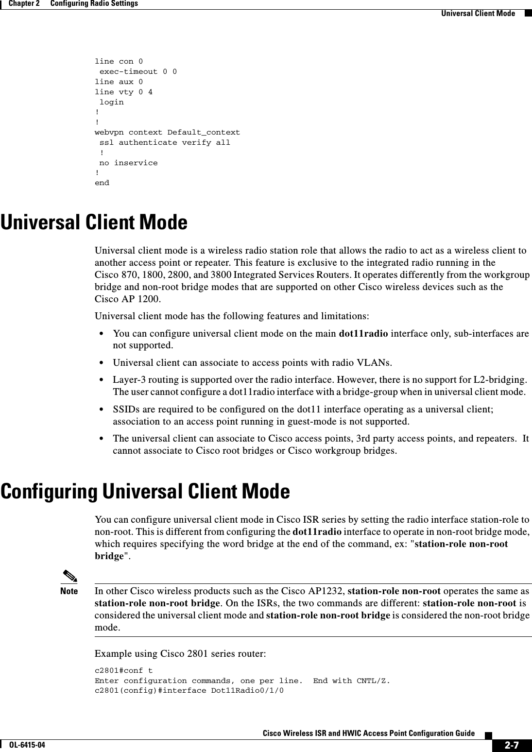
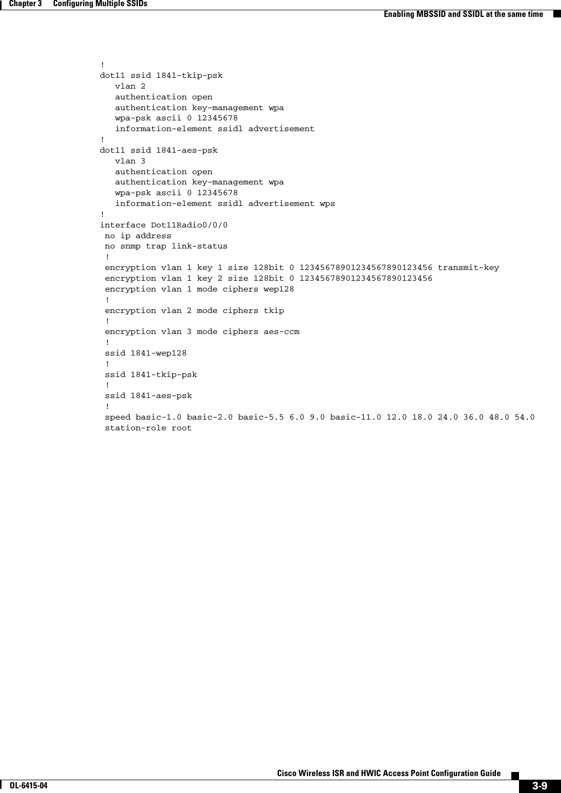
![2-20Cisco Wireless ISR and HWIC Access Point Configuration GuideOL-6415-04Chapter 2 Configuring Radio Settings Enabling and Disabling World ModeConfirming that DFS is EnabledUse the show controller dot11radio1 command to confirm that DFS is enabled. This example shows a line from the output for the show controller command for a channel on which DFS is enabled:Current Frequency: 5300 MHz Channel 60 (DFS enabled)Blocking Channels from DFS SelectionIf your regulatory domain limits the channels that you can use in specific locations--for example, indoors or outdoors--you can block groups of channels to prevent the access point from selecting them when DFS is enabled. Use this configuration interface command to block groups of channels from DFS selection:[no] dfs band [1] [2] [3] [4] blockThe 1, 2, 3, and 4 options designate blocks of channels: • 1—Specifies frequencies 5.150 to 5.250 GHz. This group of frequencies is also known as the UNII-1 band. • 2—Specifies frequencies 5.250 to 5.350 GHz. This group of frequencies is also known as the UNII-2 band. • 3—Specifies frequencies 5.470 to 5.725 GHz. • 4—Specifies frequencies 5.725 to 5.825 GHz. This group of frequencies is also known as the UNII-3 band.This example shows how to prevent the access point from selecting frequencies 5.150 to 5.350 GHz during DFS:router(config-if)# dfs band 1 2 blockThis example shows how to unblock frequencies 5.150 to 5.350 for DFS:router(config-if)# no dfs band 1 2 blockThis example shows how to unblock all frequencies for DFS:router(config-if)# no dfs band blockEnabling and Disabling World ModeYou c an c on fi g u r e t he w ir el es s devi c e t o s u pp or t 80 2. 11 d w or ld m od e or C i s c o l ega cy w o rl d mo de . When you enable world mode, the wireless device adds channel carrier set information to its beacon. Client devices with world mode enabled receive the carrier set information and adjust their settings automatically. For example, a client device used primarily in Japan could rely on world mode to adjust its channel and power settings automatically when it travels to Italy and joins a network there. Cisco client devices running firmware version 5.30.17 or later detect whether the wireless device is using 802.11d or Cisco legacy world mode and automatically use world mode that matches the mode used by the wireless device. World mode is disabled by default.](https://usermanual.wiki/Cisco-Systems/TG2050.Host-System-configuration-guide/User-Guide-1779203-Page-44.png)


![3-3Cisco Wireless ISR and HWIC Access Point Configuration GuideOL-6415-04Chapter 3 Configuring Multiple SSIDs Configuring Multiple SSIDsConfiguring Multiple SSIDsThis section contains configuration information for multiple SSIDs: • Creating an SSID Globally, page 3-3 • Using a RADIUS Server to Restrict SSIDs, page 3-5Note In Cisco IOS Release 12.4(15)T and later, you configure SSIDs globally and then apply them to a specific radio interface. Follow the instructions in the “Creating an SSID Globally” section on page 3-3 to configure SSIDs globally. Creating an SSID GloballyIn Cisco IOS Releases 12.4 and later, you can configure SSIDs globally or for a specific radio interface. When you use the dot11 ssid global configuration command to create an SSID, you can use the ssid configuration interface command to assign the SSID to a specific interface. When an SSID has been created in global configuration mode, the ssid configuration interface command attaches the SSID to the interface but does not enter ssid configuration mode. However, if the SSID has not been created in global configuration mode, the ssid command puts the CLI into SSID configuration mode for the new SSID.Note SSIDs created in Cisco IOS Releases 12.3(7)JA and later become invalid if you downgrade the software version to an earlier release.Beginning in privileged EXEC mode, follow these steps to create an SSID globally. After you create an SSID, you can assign it to specific radio interfaces.Command PurposeStep 1 configure terminal Enter global configuration mode.Step 2 dot11 ssid ssid-string Create an SSID and enter SSID configuration mode for the new SSID. The SSID can consist of up to 32 alphanumeric characters. SSIDs are case sensitive.Note +, ., ], ?, $, TAB, and trailing spaces are invalid characters for SSIDs.Step 3 authentication client username username password password(Optional) Set an authentication username and password that the access point uses to authenticate to the network when in repeater mode. Set the username and password on the SSID that the repeater access point uses to associate to a root access point, or with another repeater.Step 4 accounting list-name (Optional) Enable RADIUS accounting for this SSID. For list-name, specify the accounting method list. Click this link for more information on method lists: http://www.cisco.com/univercd/cc/td/doc/product/software/ios122/122cgcr/fsecur_c/fsaaa/scfacct.htm#xtocid2](https://usermanual.wiki/Cisco-Systems/TG2050.Host-System-configuration-guide/User-Guide-1779203-Page-57.png)
 Designate the SSID as the SSID that other access points and workgroup bridges use to associate to this access point. If you do not designate an SSID as the infrastructure SSID, infrastructure devices can associate to the access point using any SSID. If you designate an SSID as the infrastructure SSID, infrastructure devices must associate to the access point using that SSID unless you also enter the optional keyword.Step 8 interface dot11radio { 0 | 1 }Enter interface configuration mode for the radio interface to which you want to assign the SSID. The 2.4-GHz radio is radio 0, and the 5-GHz radio is radio 1.Step 9 ssid ssid-string Assign the global SSID that you created in Step 2 to the radio interface.Step 10 end Return to privileged EXEC mode.Step 11 copy running-config startup-config (Optional) Save your entries in the configuration file.Command Purpose](https://usermanual.wiki/Cisco-Systems/TG2050.Host-System-configuration-guide/User-Guide-1779203-Page-58.png)
![3-5Cisco Wireless ISR and HWIC Access Point Configuration GuideOL-6415-04Chapter 3 Configuring Multiple SSIDs Configuring Multiple SSIDsViewing SSIDs Configured GloballyUse this command to view configuration details for SSIDs that are configured globally:router# show running-config ssid ssid-stringUsing Spaces in SSIDsIn Cisco IOS Release 12.4(15)T, you can include spaces in an SSID, but trailing spaces (spaces at the end of an SSID) are invalid. However, any SSIDs created in previous versions having trailing spaces are recognized. Trailing spaces make it appear that you have identical SSIDs configured on the same access point. If you think identical SSIDs are on the access point, use the show dot11 associations privileged EXEC command to check any SSIDs created in a previous release for trailing spaces.For example, this sample output from a show configuration privileged EXEC command does not show spaces in SSIDs:ssid buffalo vlan 77 authentication openssid buffalo vlan 17 authentication openssid buffalo vlan 7 authentication openHowever, this sample output from a show dot11 associations privileged EXEC command shows the spaces in the SSIDs:SSID [buffalo] :SSID [buffalo ] :SSID [buffalo ] :Using a RADIUS Server to Restrict SSIDsTo prevent client devices from associating to the access point using an unauthorized SSID, you can create a list of authorized SSIDs that clients must use on your RADIUS authentication server. The SSID authorization process consists of these steps:1. A client device associates to the access point using any SSID configured on the access point. 2. The client begins RADIUS authentication.3. The RADIUS server returns a list of SSIDs that the client is allowed to use. The access point checks the list for a match of the SSID used by the client. There are three possible outcomes:a. If the SSID that the client used to associate to the access point matches an entry in the allowed list returned by the RADIUS server, the client is allowed network access after completing all authentication requirements. b. If the access point does not find a match for the client in the allowed list of SSIDs, the access point disassociates the client. c. If the RADIUS server does not return any SSIDs (no list) for the client, then the administrator has not configured the list, and the client is allowed to associate and attempt to authenticate.](https://usermanual.wiki/Cisco-Systems/TG2050.Host-System-configuration-guide/User-Guide-1779203-Page-59.png)
![3-7Cisco Wireless ISR and HWIC Access Point Configuration GuideOL-6415-04Chapter 3 Configuring Multiple SSIDs Enabling MBSSID and SSIDL at the same time • When multiple BSSIDs are enabled on the access point, the SSIDL IE does not contain a list of SSIDs; it contains only extended capabilities. • Any Wi-Fi certified client device can associate to an access point using multiple BSSIDs. • You can enable multiple BSSIDs on access points that participate in WDS.CLI Configuration ExampleThis example shows the CLI commands that you use to enable multiple BSSIDs on a radio interface, create an SSID called visitor, designate the SSID as a BSSID, specify that the BSSID is included in beacons, set a DTIM period for the BSSID, and assign the SSID visitor to the radio interface: router(config)# interface dot11 0router(config-if)# mbssidrouter(config-if)# exitrouter(config)# dot11 ssid visitorrouter(config-ssid)# mbssid guest-mode router(config-ssid)# exitrouter(config)# interface dot11 0router(config-if)# ssid visitorYou c an a ls o us e t h e dot11 mbssid global configuration command to simultaneously enable multiple BSSIDs on all radio interfaces that support multiple BSSIDs.Displaying Configured BSSIDsUse the show dot11 bssid privileged EXEC command to display the relationship between SSIDs and BSSIDs or MAC addresses. This example shows the command output:router1230#show dot11 bssidInterface BSSID Guest SSIDDot11Radio1 0011.2161.b7c0 Yes atlanticDot11Radio0 0005.9a3e.7c0f Yes WPA2-TLS-gEnabling MBSSID and SSIDL at the same timeWhen multiple BSSIDs are enabled on the access point, the SSIDL IE does not contain a list of SSIDs; it contains only extended capabilities.Beginning in privileged EXEC mode, follow these steps to include an SSID in an SSIDL IE:Command PurposeStep 1 configure terminal Enter global configuration mode.Step 2 interface dot11radio { 0 | 1 }Enter interface configuration mode for the radio interface. Step 3 ssid ssid-string Enter configuration mode for a specific SSID.Step 4 information-element ssidl [advertisement] [wps]Include an SSIDL IE in the access point beacon that advertises the access point’s extended capabilities, such as 802.1x and support for Microsoft Wireless Provisioning Services (WPS).Use the advertisement option to include the SSID name and capabilities in the SSIDL IE. Use the wps option to set the WPS capability flag in the SSIDL IE.](https://usermanual.wiki/Cisco-Systems/TG2050.Host-System-configuration-guide/User-Guide-1779203-Page-61.png)

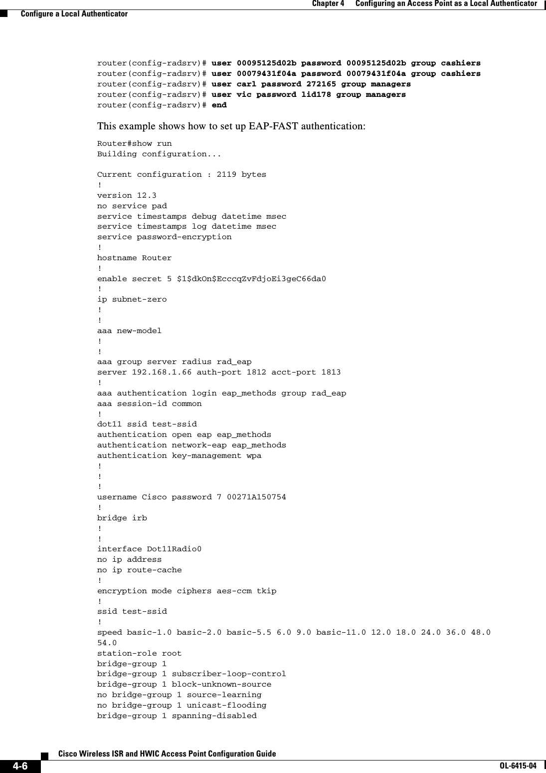
![4-5Cisco Wireless ISR and HWIC Access Point Configuration GuideOL-6415-04Chapter 4 Configuring an Access Point as a Local Authenticator Configure a Local AuthenticatorThis example shows how to set up a local authenticator used by three access points with three user groups and several users:router# configure terminalrouter(config)# radius-server localrouter(config-radsrv)# nas 10.91.6.159 key 110337router(config-radsrv)# nas 10.91.6.162 key 110337router(config-radsrv)# nas 10.91.6.181 key 110337router(config-radsrv)# group clerksrouter(config-radsrv-group)# vlan 87router(config-radsrv-group)# ssid batmanrouter(config-radsrv-group)# ssid robinrouter(config-radsrv-group)# reauthentication time 1800router(config-radsrv-group)# block count 2 time 600router(config-radsrv-group)# group cashiersrouter(config-radsrv-group)# vlan 97router(config-radsrv-group)# ssid deerrouter(config-radsrv-group)# ssid anteloperouter(config-radsrv-group)# ssid elkrouter(config-radsrv-group)# reauthentication time 1800router(config-radsrv-group)# block count 2 time 600router(config-radsrv-group)# group managersrouter(config-radsrv-group)# vlan 77router(config-radsrv-group)# ssid mouserouter(config-radsrv-group)# ssid chipmunkrouter(config-radsrv-group)# reauthentication time 1800router(config-radsrv-group)# block count 2 time 600router(config-radsrv-group)# exitrouter(config-radsrv)# user jsmith password twain74 group clerksrouter(config-radsrv)# user stpatrick password snake100 group clerksrouter(config-radsrv)# user nick password uptown group clerksrouter(config-radsrv)# user 00095125d02b password 00095125d02b group clerks mac-auth-onlyStep 11 user username { password | nthash } password [ group group-name ] [mac-auth-only] Enter the LEAP and EAP-FAST users allowed to authenticate using the local authenticator. You must enter a username and password for each user. If you only know the NT value of the password, which you can often find in the authentication server database, you can enter the NT hash as a string of hexadecimal digits.To add a client device for MAC-based authentication, enter the client’s MAC address as both the username and password. Enter 12 hexadecimal digits without a dot or dash between the numbers as the username and the password. For example, for the MAC address 0009.5125.d02b, enter 00095125d02b as both the username and the password.To limit the user to MAC authentication only, enter mac-auth-only.To add the user to a user group, enter the group name. If you do not specify a group, the user is not assigned to a specific VLAN and is never forced to reauthenticate.Step 12 end Return to privileged EXEC mode.Step 13 copy running-config startup-config(Optional) Save your entries in the configuration file.Command Purpose](https://usermanual.wiki/Cisco-Systems/TG2050.Host-System-configuration-guide/User-Guide-1779203-Page-69.png)
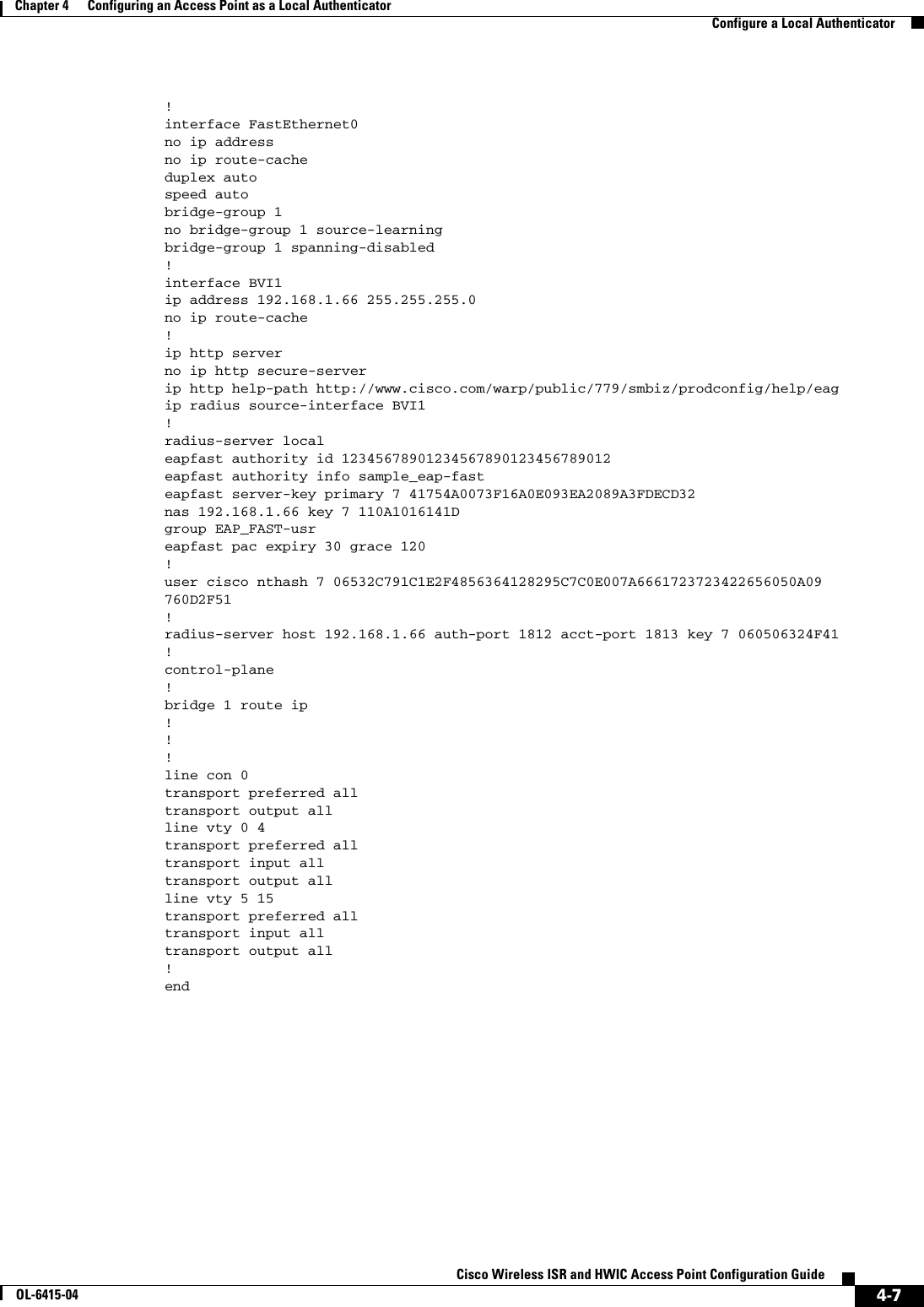
![4-9Cisco Wireless ISR and HWIC Access Point Configuration GuideOL-6415-04Chapter 4 Configuring an Access Point as a Local Authenticator Configure a Local AuthenticatorConfiguring EAP-FAST SettingsThe default settings for EAP-FAST authentication are suitable for most wireless LANs. However, you can customize the credential timeout values, authority ID, and server keys to match your network requirements.Configuring PAC SettingsThis section describes how to configure Protected Access Credential (PAC) settings. The first time that an EAP-FAST client device attempts to authenticate to the local authenticator, the local authenticator generates a PAC for the client. You can also generate PACs manually and use the Aironet Client Utility to import the PAC file.PAC Expiration TimesYou c an l i mi t t he nu mb e r o f d a y s f o r w h i ch PACs a re va l id , a n d a g r a c e pe ri od d u r i n g w h i c h PACs a r e valid after they have expired. By default, PACs are valid for infinite days, with a grace period of infinite days. You apply the expiration time and the grace period settings to a group of users.Use this command to configure the expiration time and grace period for PACs:router(config-radsrv-group)# [no] eapfast pac expiry days [grace days] Enter a number of days from 2 to 4095. Enter the no form of the command to reset the expiration time or grace period to infinite days.In this example, PACs for the user group expire in 100 days with a grace period of two days:router(config-radsrv-group)# eapfast pac expiry 100 grace 2Generating PACs ManuallyThe local authenticator automatically generates PACs for EAP-FAST clients that request them. However, you might need to generate a PAC manually for some client devices. When you enter the command, the local authenticator generates a PAC file and writes it to the network location that you specify. The user imports the PAC file into the client profile.Use this command to generate a PAC manually:router# radius local-server pac-generate filename username [password password] [expiry days]When you enter the PAC filename, enter the full path to which the local authenticator writes the PAC file (such as tftp://172.1.1.1/test/user.pac). The password is optional and, if not specified, a default password understood by the CCX client is used. Expiry is also optional and, if not specified, the default period is 1 day.In this example, the local authenticator generates a PAC for the username joe, password-protects the file with the password bingo, sets the PAC to expire in 10 days, and writes the PAC file to the TFTP server at 10.0.0.5:router# radius local-server pac-generate tftp://10.0.0.5 joe password bingo expiry 10](https://usermanual.wiki/Cisco-Systems/TG2050.Host-System-configuration-guide/User-Guide-1779203-Page-73.png)
![4-10Cisco Wireless ISR and HWIC Access Point Configuration GuideOL-6415-04Chapter 4 Configuring an Access Point as a Local Authenticator Configure a Local AuthenticatorConfiguring an Authority IDAll EAP-FAST authenticators are identified by an authority identity (AID). The local authenticator sends its AID to an authenticating client, and the client checks its database for a matching AID. If the client does not recognize the AID, it requests a new PAC. Use these commands to assign an AID to the local authenticator:router(config-radserv)# [no] eapfast authority id identifierrouter(config-radserv)# [no] eapfast authority info identifierThe eapfast authority id command assigns an AID that the client device uses during authentication. Configuring Server KeysThe local authenticator uses server keys to encrypt PACs that it generates and to decrypt PACs when authenticating clients. The server maintains two keys, a primary key and a secondary key, and uses the primary key to encrypt PACs. By default, the server uses a default value as the primary key but does not use a secondary key unless you configure one.When the local authenticator receives a client PAC, it attempts to decrypt the PAC with the primary key. If decryption fails with the primary, the authenticator attempts to decrypt the PAC with the secondary key if one is configured. If decryption fails, the authenticator rejects the PAC as invalid. Use these commands to configure server keys:router(config-radsrv)# [no] eapfast server-key primary {[auto-generate] | [ [0 | 7] key]} router(config-radsrv)# [no] eapfast server-key secondary [0 | 7] key Keys can contain up to 32 hexadecimal digits. Enter 0 before the key to enter an unencrypted key. Enter 7 before the key to enter an encrypted key. Use the no form of the commands to reset the local authenticator to the default setting, which is to use a default value as a primary key.Possible PAC Failures Caused by Access Point ClockThe local authenticator uses the access point clock to both generate PACs and to determine whether PACs are valid. However, relying on the access point clock can lead to PAC failures.If your local authenticator access point receives its time setting from an NTP server, there is an interval between boot up and synchronization with the NTP server during which the access point uses its default time setting. If the local authenticator generates a PAC during that interval, the PAC might be expired when the access point receives a new time setting from the NTP server. If an EAP-FAST client attempts to authenticate during the interval between boot and NTP-synch, the local authenticator might reject the client’s PAC as invalid. If your local authenticator does not receive its time setting from an NTP server and it reboots frequently, PACs generated by the local authenticator might not expire when they should. The access point clock is reset when the access point reboots, so the elapsed time on the clock would not reach the PAC expiration time.](https://usermanual.wiki/Cisco-Systems/TG2050.Host-System-configuration-guide/User-Guide-1779203-Page-74.png)
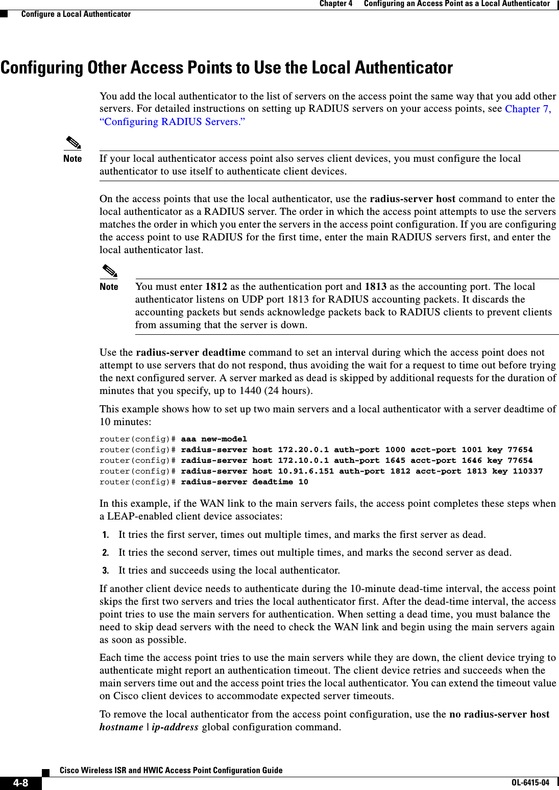
![4-11Cisco Wireless ISR and HWIC Access Point Configuration GuideOL-6415-04Chapter 4 Configuring an Access Point as a Local Authenticator Configure a Local AuthenticatorLimiting the Local Authenticator to One Authentication TypeBy default, a local authenticator access point performs LEAP, EAP-FAST, and MAC-based authentication for client devices. However, you can limit the local authenticator to perform only one or two authentication types. Use the no form of the authentication command to restrict the authenticator to an authentication type:router(config-radsrv)# [no] authentication [eapfast] [leap] [mac] Because all authentication types are enabled by default, you enter the no form of the command to disable authentication types. For example, if you want the authenticator to perform only LEAP authentication, you enter these commands:router(config-radsrv)# no authentication eapfast router(config-radsrv)# no authentication mac Unblocking Locked UsernamesYou c a n u nb l oc k u s e r n a m es be f o r e t he lo c k o ut ti me exp i r e s , o r wh e n t h e l oc k ou t t im e i s se t to in fin i te . In Privileged Exec mode on the local authenticator, enter this command to unblock a locked username:router# clear radius local-server user username Viewing Local Authenticator StatisticsIn privileged exec mode, enter this command to view statistics collected by the local authenticator:router# show radius local-server statistics This example shows local authenticator statistics:Successes : 0 Unknown usernames : 0Client blocks : 0 Invalid passwords : 0Unknown NAS : 0 Invalid packet from NAS: 0NAS : 10.91.6.158Successes : 0 Unknown usernames : 0Client blocks : 0 Invalid passwords : 0Corrupted packet : 0 Unknown RADIUS message : 0No username attribute : 0 Missing auth attribute : 0Shared key mismatch : 0 Invalid state attribute: 0Unknown EAP message : 0 Unknown EAP auth type : 0Auto provision success : 0 Auto provision failure : 0PAC refresh : 0 Invalid PAC received : 0Username Successes Failures Blocksnicky 0 0 0jones 0 0 0jsmith 0 0 0Router#sh radius local-server statisticsSuccesses : 1 Unknown usernames : 0Client blocks : 0 Invalid passwords : 0Unknown NAS : 0 Invalid packet from NAS: 0 The first section of statistics lists cumulative statistics from the local authenticator.](https://usermanual.wiki/Cisco-Systems/TG2050.Host-System-configuration-guide/User-Guide-1779203-Page-75.png)
![5-4Cisco Wireless ISR and HWIC Access Point Configuration GuideOL-6415-04Chapter 5 Configuring Encryption Types Configure Encryption TypesThis example shows how to create a 128-bit WEP key in slot 3 for VLAN 22 and sets the key as the transmit key:router# configure terminalrouter(config)# interface dot11radio 0router(config-if)# encryption vlan 22 key 3 size 128 12345678901234567890123456 transmit-keyrouter(config-ssid)# endWEP Key Restrictions Table 5-1 lists WEP key restrictions based on your security configuration.Step 3 encryption [vlan vlan-id] key 1-4 size { 40 | 128 } encryption-key [ 0 | 7 ] [transmit-key]Create a WEP key and set up its properties. • (Optional) Select the VLAN for which you want to create a key. • Name the key slot in which this WEP key resides. You can assign up to 4 WEP keys for each VLAN. • Enter the key and set the size of the key, either 40-bit or 128-bit. 40-bit keys contain 10 hexadecimal digits; 128-bit keys contain 26 hexadecimal digits. • (Optional) Specify whether the key is encrypted (7) or unencrypted (0). • (Optional) Set this key as the transmit key. The key in slot 1 is the transmit key by default. Note Using security features such as authenticated key management can limit WEP key configurations. See the “WEP Key Restrictions” section on page 5-4 for a list of features that impact WEP keys.Step 4 end Return to privileged EXEC mode.Step 5 copy running-config startup-config (Optional) Save your entries in the configuration file.Command PurposeTa b l e 5-1 WEP Key Restrictions Security Configuration WEP Key RestrictionWPA authenticated key management Cannot configure a WEP key in key slot 1LEAP or EAP authentication Cannot configure a WEP key in key slot 4Cipher suite with 40-bit WEP Cannot configure a 128-bit keyCipher suite with 128-bit WEP Cannot configure a 40-bit keyCipher suite with TKIP Cannot configure any WEP keys](https://usermanual.wiki/Cisco-Systems/TG2050.Host-System-configuration-guide/User-Guide-1779203-Page-80.png)
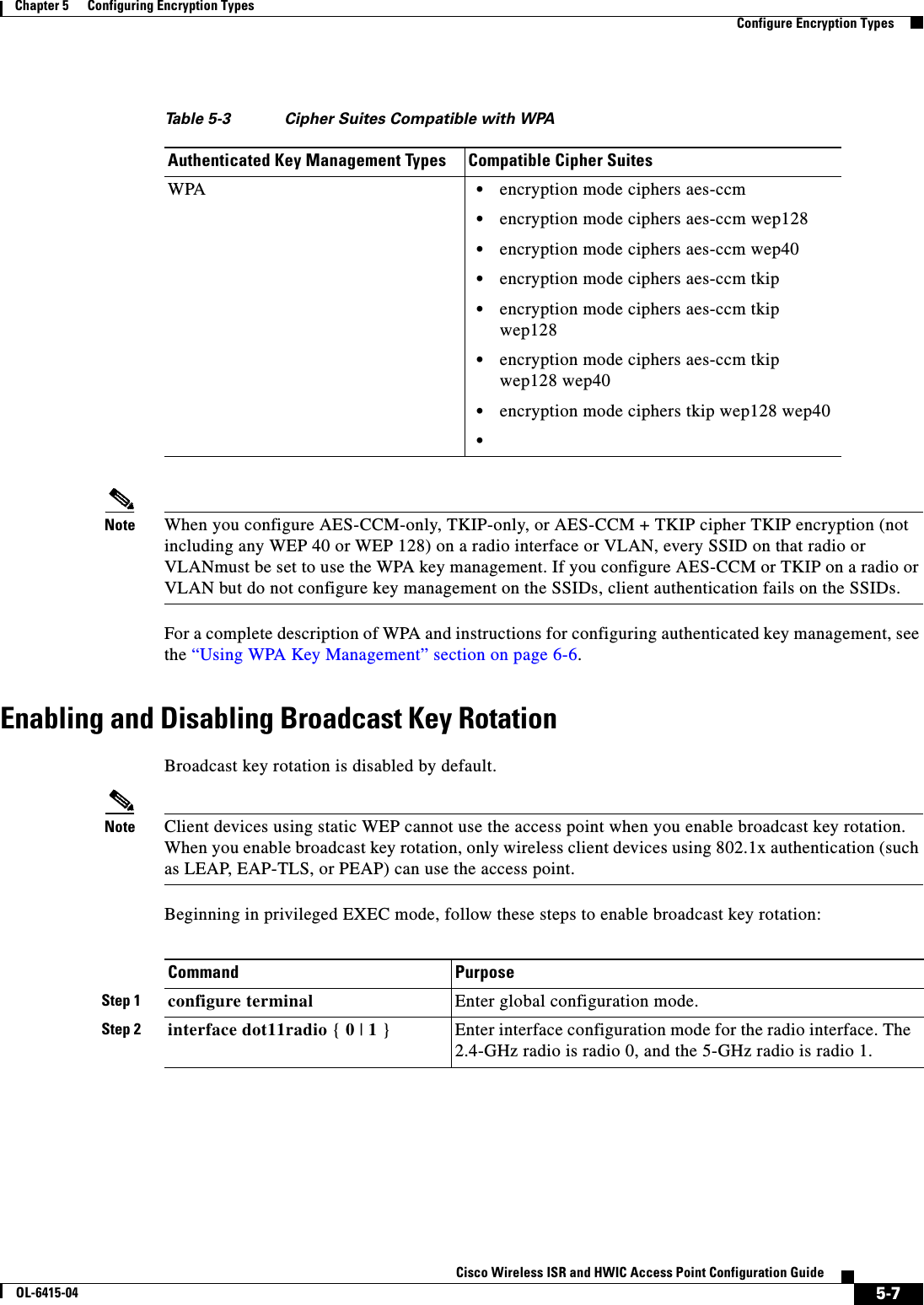
![5-6Cisco Wireless ISR and HWIC Access Point Configuration GuideOL-6415-04Chapter 5 Configuring Encryption Types Configure Encryption TypesUse the no form of the encryption command to disable a cipher suite.This example sets up a cipher suite for VLAN 22 that enables AES-CCM, and 128-bit WEP.router# configure terminalrouter(config)# interface dot11radio 0router(config-if)# encryption vlan 22 mode ciphers aes-ccm wep128router(config-if)# exitCipher Suites Compatible with WPA If you configure your access point to use WPA authenticated key management, you must select a cipher suite compatible with the authenticated key management type. Table 5-3 lists the cipher suites that are compatible with WPA.Step 3 encryption [vlan vlan-id] mode ciphers {[aes-ccm | tkip]} {[wep128 | wep40]}Enable a cipher suite containing the encryption you need. Table 5-3 lists guidelines for selecting a cipher suite that matches the type of authenticated key management you configure. • (Optional) Select the VLAN for which you want to enable WEP and WEP features. • Set the cipher options and WEP level. You can combine TKIP with 128-bit or 40-bit WEP.Note You can also use the encryption mode wep command to set up static WEP. However, you should use encryption mode wep only if no clients that associate to the access point are capable of key management. See the Cisco IOS Command Reference for Cisco Access Points and Bridges for a detailed description of the encryption mode wep command.Note When you configure the cipher TKIP and AES-CCM (not TKIP + WEP 128 or TKIP + WEP 40) for an SSID, the SSID must use WPA key management. Client authentication fails on an SSID that uses the cipher TKIP without enabling WPA key management.Step 4 end Return to privileged EXEC mode.Step 5 copy running-config startup-config (Optional) Save your entries in the configuration file.Command Purpose](https://usermanual.wiki/Cisco-Systems/TG2050.Host-System-configuration-guide/User-Guide-1779203-Page-82.png)
![5-8Cisco Wireless ISR and HWIC Access Point Configuration GuideOL-6415-04Chapter 5 Configuring Encryption Types Configure Encryption TypesUse the no form of the encryption command to disable broadcast key rotation.This example enables broadcast key rotation on VLAN 22 and sets the rotation interval to 300 seconds:router# configure terminalrouter(config)# interface dot11radio 0routerrouter(config-if)# broadcast-key vlan 22 change 300router(config-ssid)# endSecurity Type in Universal Client ModeSecurityIn universal client mode, the security type must be configured exactly as that of the access point it is associating to. For example, if the access point is configured with AES and TKIP encryption, the universal client must also have AES+TKIP in order for the devices to associate properly.Step 3 broadcast-key change seconds [ vlan vlan-id ] [ membership-termination ] [ capability-change ]Enable broadcast key rotation. • Enter the number of seconds between each rotation of the broadcast key. • (Optional) Enter a VLAN for which you want to enable broadcast key rotation. • (Optional) If you enable WPA authenticated key management, you can enable additional circumstances under which the access point changes and distributes the WPA group key. –Membership termination—the access point generates and distributes a new group key when any authenticated client device disassociates from the access point. This feature protects the privacy of the group key for associated clients. However, it might generate some overhead if clients on your network roam frequently. –Capability change—the access point generates and distributes a dynamic group key when the last non-key management (static WEP) client disassociates, and it distributes the statically configured WEP key when the first non-key management (static WEP) client authenticates. In WPA migration mode, this feature significantly improves the security of key-management capable clients when there are no static-WEP clients associated to the access point.See Chapter 6, “Configuring Authentication Types,” for detailed instructions on enabling authenticated key management.Step 4 end Return to privileged EXEC mode.Step 5 copy running-config startup-config (Optional) Save your entries in the configuration file.Command Purpose](https://usermanual.wiki/Cisco-Systems/TG2050.Host-System-configuration-guide/User-Guide-1779203-Page-84.png)
![5-10Cisco Wireless ISR and HWIC Access Point Configuration GuideOL-6415-04Chapter 5 Configuring Encryption Types Configure Encryption TypesDebuggingTo determine if the universal client has associated to the access point, the user can issue the 'show dot11 association all' command for a detailed output of which access point it was associating to and how it has associated to the access point.The "show dot11 association" command will have the following output:c2801_uc#c2801_uc#sh dot11 ass allAddress : 0015.2b06.17d0 Name : apIP Address : 200.1.1.1 Interface : Dot11Radio0/1/0Device : ap1200-Parent Software Version : 12.3CCX Version : NONEState : Assoc Parent : Our Parent SSID : test10 VLAN : 0Hops to Infra : 0 Association Id : 1Tunnel Address : 0.0.0.0Key Mgmt type : NONE Encryption : OffCurrent Rate : 54.0 Capability : WMM ShortHdr ShortSlotSupported Rates : 1.0 2.0 5.5 6.0 9.0 11.0 12.0 18.0 24.0 36.0 48.0 54.0Signal Strength : -14 dBm Connected for : 236 secondsSignal Quality : N/A Activity Timeout : 15 secondsPower-save : Off Last Activity : 0 seconds agoPackets Input : 2449 Packets Output : 15 Bytes Input : 451711 Bytes Output : 4664 Duplicates Rcvd : 3 Data Retries : 1 Decrypt Failed : 0 RTS Retries : 0 MIC Failed : 0 MIC Missing : 0 Packets Redirected: 0 Redirect Filtered: 0 c2801_uc#CaveatsWhen the Cisco dot11radio is in the universal client mode and associates to a 3rd party access point, there are some additional caveats. The first is on the "show dot11 association" output. The "Device" area shows a result of "unknown" when associated to a 3rd party access point (non-Cisco). In the example below, a Cisco 876W universal client is associated to a Symbol 4131 Access Point. The "Software Ver si on " a n d " N a m e " fie ld s a ls o r es u l t in " N O NE ". This is because the Cisco Aironet messages between Cisco devices carry this information and not between 3rd party and Cisco devices.Example:c876#sh dot11 assoc802.11 Client Stations on Dot11Radio0: SSID [symbol] : MAC Address IP address Device Name Parent State 00a0.f8dc.133a 192.168.1.4 unknown - - Assoc c876#sh dot11 ass allAddress : 00a0.f8dc.133a Name : NONEIP Address : 192.168.1.4 Interface : Dot11Radio0Device : unknown Software Version : NONE CCX Version : NONEState : Assoc Parent : Our Parent](https://usermanual.wiki/Cisco-Systems/TG2050.Host-System-configuration-guide/User-Guide-1779203-Page-86.png)

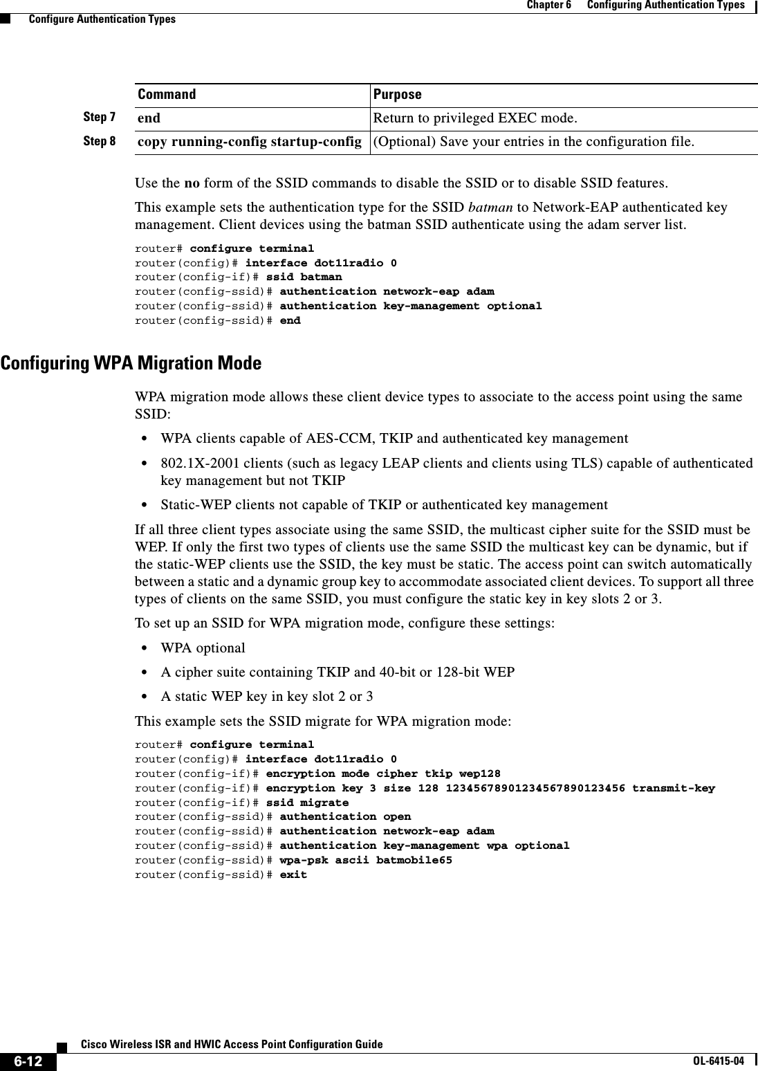
![6-10Cisco Wireless ISR and HWIC Access Point Configuration GuideOL-6415-04Chapter 6 Configuring Authentication Types Configure Authentication TypesStep 3 authentication open [mac-address list-name [alternate]] [[optional] eap list-name](Optional) Set the authentication type to open for this SSID. Open authentication allows any device to authenticate and then attempt to communicate with the access point. Note The following EAP methods are supported: EAP-MD5, EAP_SIM, EAP-TTLS, EAP-LEAP, EAP-PEAP (v0 and v1), EAP-TLS, AND EAP-FAST. • (Optional) Set the SSID authentication type to open with MAC address authentication. The access point forces all client devices to perform MAC-address authentication before they are allowed to join the network. For list-name, specify the authentication method list. Click this link for more information on method lists: http://www.cisco.com/univercd/cc/td/doc/product/software/ios122/122cgcr/fsecur_c/fsaaa/scfathen.htm#xtocid2Use the alternate keyword to allow client devices to join the network using either MAC or EAP authentication; clients that successfully complete either authentication are allowed to join the network. • (Optional) Set the SSID authentication type to open with EAP authentication. The access point forces all client devices to perform EAP authentication before they are allowed to join the network. For list-name, specify the authentication method list. Use the optional keyword to allow client devices using either open or EAP authentication to associate and become authenticated. This setting is used mainly by service providers that require special client accessibility.Note An access point configured for EAP authentication forces all client devices that associate to perform EAP authentication. Client devices that do not use EAP cannot use the access point.Command Purpose](https://usermanual.wiki/Cisco-Systems/TG2050.Host-System-configuration-guide/User-Guide-1779203-Page-98.png)
![6-11Cisco Wireless ISR and HWIC Access Point Configuration GuideOL-6415-04Chapter 6 Configuring Authentication Types Configure Authentication TypesStep 4 authentication shared [mac-address list-name] [eap list-name](Optional) Set the authentication type for the SSID to shared key.Note Because of shared key's security flaws, Cisco recommends that you avoid using it.Note You can assign shared key authentication to only one SSID. • (Optional) Set the SSID’s authentication type to shared key with MAC address authentication. For list-name, specify the authentication method list. • (Optional) Set the SSID’s authentication type to shared key with EAP authentication. For list-name, specify the authentication method list.Step 5 authentication network-eap list-name [mac-address list-name](Optional) Set the authentication type for the SSID to Network-EAP. Using the Extensible Authentication Protocol (EAP) to interact with an EAP-compatible RADIUS server, the access point helps a wireless client device and the RADIUS server to perform mutual authentication and derive a dynamic unicast WEP key. However, the access point does not force all client devices to perform EAP authentication. • (Optional) Set the SSID’s authentication type to Network-EAP with MAC address authentication. All client devices that associate to the access point are required to perform MAC-address authentication. For list-name, specify the authentication method list. Step 6 authentication key-management { [wpa]} [ optional ](Optional) Set the authentication type for the SSID to WPA. If you use the optional keyword, client devices other than WPA clients can use this SSID. If you do not use the optional keyword, only WPA client devices are allowed to use the SSID.When Network EAP is enabled for an SSID, client devices using LEAP, EAP-FAST, PEAP/GTC, MSPEAP, and EAP-TLS can authenticate using the SSID.To enable WPA for an SSID, you must also enable Open authentication or Network-EAP or both.Note Before you can enable WPA, you must set the encryption mode for the SSID’s VLAN to one of the cipher suite options. See the “Configure Encryption Types” section on page 5-3 for instructions on configuring the VLAN encryption mode.Note If you enable WPA for an SSID without a pre-shared key, the key management type is WPA. If you enable WPA with a pre-shared key, the key management type is WPA-PSK. See the “Configuring Additional WPA Settings” section on page 6-13 for instructions on configuring a pre-shared key.Command Purpose](https://usermanual.wiki/Cisco-Systems/TG2050.Host-System-configuration-guide/User-Guide-1779203-Page-99.png)
![6-13Cisco Wireless ISR and HWIC Access Point Configuration GuideOL-6415-04Chapter 6 Configuring Authentication Types Configure Authentication TypesConfiguring Additional WPA SettingsUse two optional settings to configure a pre-shared key on the access point and adjust the frequency of group key updates.Setting a Pre-Shared KeyTo support WPA on a wireless LAN where 802.1x-based authentication is not available, you must configure a pre-shared key on the access point. You c an e nt er t he p re -s ha r ed key a s AS CI I or hexadecimal characters. If you enter the key as ASCII characters, you enter between 8 and 63 characters, and the access point expands the key using the process described in the Password-based Cryptography Standard (RFC2898). If you enter the key as hexadecimal characters, you must enter 64 hexadecimal characters.Configuring Group Key UpdatesIn the last step in the WPA process, the access point distributes a group key to the authenticated client device. You can use these optional settings to configure the access point to change and distribute the group key based on client association and disassociation: • Membership termination—the access point generates and distributes a new group key when any authenticated device disassociates from the access point. This feature keeps the group key private for associated devices, but it might generate some overhead traffic if clients on your network roam frequently among access points. • Capability change—the access point generates and distributes a dynamic group key when the last non-key management (static WEP) client disassociates, and it distributes the statically configured WEP key when the first non-key management (static WEP) client authenticates. In WPA migration mode, this feature significantly improves the security of key-management capable clients when there are no static-WEP clients associated to the access point.Beginning in privileged EXEC mode, follow these steps to configure a WPA pre-shared key and group key update options:Command PurposeStep 1 configure terminal Enter global configuration mode.Step 2 interface dot11radio { 0 | 1 }Enter interface configuration mode for the radio interface. The 2.4-GHz radio is radio 0, and the 5-GHz radio is radio 1.Step 3 ssid ssid-string Enter SSID configuration mode for the SSID. Step 4 wpa-psk { hex | ascii } [ 0 | 7 ] encryption-keyEnter a pre-shared key for client devices using WPA that also use static WEP keys.Enter the key using either hexadecimal or ASCII characters. If you use hexadecimal, you must enter 64 hexadecimal characters to complete the 256-bit key. If you use ASCII, you must enter a minimum of 8 letters, numbers, or symbols, and the access point expands the key for you. You can enter a maximum of 63 ASCII characters.Step 5 end Return to privileged EXEC mode.](https://usermanual.wiki/Cisco-Systems/TG2050.Host-System-configuration-guide/User-Guide-1779203-Page-101.png)
![6-14Cisco Wireless ISR and HWIC Access Point Configuration GuideOL-6415-04Chapter 6 Configuring Authentication Types Configure Authentication TypesThis example shows how to configure a pre-shared key for clients using WPA and static WEP, with group key update options:ap# configure terminalap(config)# interface dot11radio 0ap(config-if)# ssid batmanap(config-ssid)# wpa-psk ascii batmobile65ap(config-ssid)# exitap(config-if)# exitap(config)# broadcast-key vlan 87 membership-termination capability-changeConfiguring MAC Authentication CachingIf MAC-authenticated clients on your wireless LAN roam frequently, you can enable a MAC authentication cache on your access points. MAC authentication caching reduces overhead because the access point authenticates devices in its MAC-address cache without sending the request to your authentication server. When a client device completes MAC authentication to your authentication server, the access point adds the client’s MAC address to the cache.Beginning in privileged EXEC mode, follow these steps to enable MAC authentication caching:Step 6 broadcast-key [ vlan vlan-id ] { change seconds } [ membership-termination ] [ capability-change ]Use the broadcast key rotation command to configure additional updates of the WPA group key.Step 7 copy running-config startup-config (Optional) Save your entries in the configuration file.Command PurposeCommand PurposeStep 1 configure terminal Enter global configuration mode.Step 2 dot11 aaa authentication mac-authen filter-cache [timeout seconds]Enable MAC authentication caching on the access point.Use the timeout option to configure a timeout value for MAC addresses in the cache. Enter a value from 30 to 65555 seconds. The default value is 1800 (30 minutes). When you enter a timeout value, MAC-authentication caching is enabled automatically.Step 3 exit Return to privileged EXEC mode. Step 4 show dot11 aaa authentication mac-authen filter-cache [address]Show entries in the MAC-authentication cache. Include client MAC addresses to show entries for specific clients.Step 5 clear dot11 aaa authentication mac-authen filter-cache [address]Clear all entries in the cache. Include client MAC addresses to clear specific clients from the cache.Step 6 end Return to privileged EXEC mode.Step 7 copy running-config startup-config (Optional) Save your entries in the configuration file.](https://usermanual.wiki/Cisco-Systems/TG2050.Host-System-configuration-guide/User-Guide-1779203-Page-102.png)
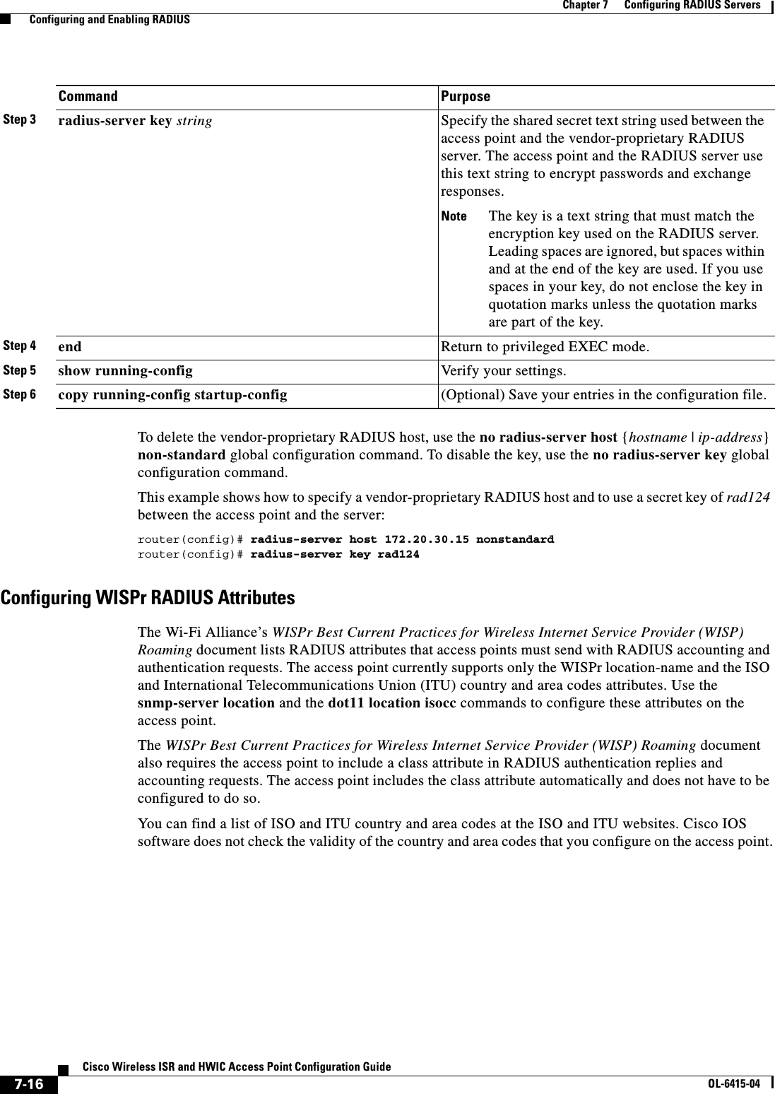
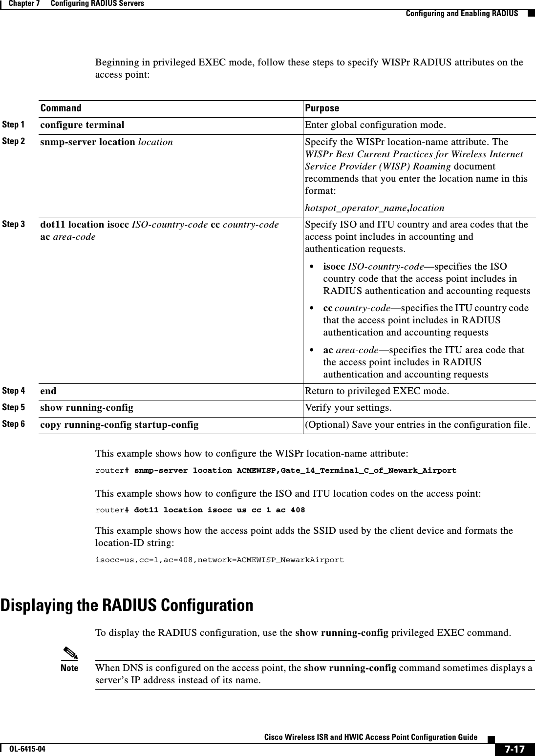
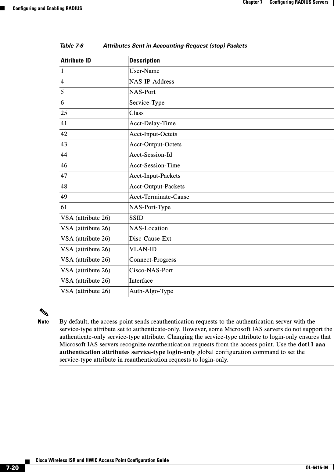
![7-6Cisco Wireless ISR and HWIC Access Point Configuration GuideOL-6415-04Chapter 7 Configuring RADIUS Servers Configuring and Enabling RADIUSStep 3 radius-server host {hostname | ip-address} [auth-port port-number] [acct-port port-number] [timeout seconds] [retransmit retries] [key string]Specify the IP address or host name of the remote RADIUS server host. • (Optional) For auth-port port-number, specify the UDP destination port for authentication requests.(Optional) For acct-port port-number, specify the UDP destination port for accounting requests. • (Optional) For timeout seconds, specify the time interval that the access point waits for the RADIUS server to reply before retransmitting. The range is 1 to 1000. This setting overrides the radius-server timeout global configuration command setting. If no timeout is set with the radius-server host command, the setting of the radius-server timeout command is used. • (Optional) For retransmit retries, specify the number of times a RADIUS request is resent to a server if that server is not responding or responding slowly. The range is 1 to 1000. If no retransmit value is set with the radius-server host command, the setting of the radius-server retransmit global configuration command is used. • (Optional) For key string, specify the authentication and encryption key used between the access point and the RADIUS daemon running on the RADIUS server. Note The key is a text string that must match the encryption key used on the RADIUS server. Always configure the key as the last item in the radius-server host command. Leading spaces are ignored, but spaces within and at the end of the key are used. If you use spaces in your key, do not enclose the key in quotation marks unless the quotation marks are part of the key.To configure the access point to recognize more than one host entry associated with a single IP address, enter this command as many times as necessary, making sure that each UDP port number is different. The access point software searches for hosts in the order in which you specify them. Set the timeout, retransmit, and encryption key values to use with the specific RADIUS host.Step 4 dot11 ssid ssid-string Enter SSID configuration mode for an SSID on which you need to enable accounting. The SSID can consist of up to 32 alphanumeric characters. SSIDs are case sensitive.Step 5 accounting list-name Enable RADIUS accounting for this SSID. For list-name, specify the accounting method list. Click this URL for more information on method lists: http://www.cisco.com/univercd/cc/td/doc/product/software/ios122/122cgcr/fsecur_c/fsaaa/scfacct.htm#xtocid2Note To enable accounting for an SSID, you must include the accounting command in the SSID configuration. Click this URL to browse to a detailed description of the SSID configuration mode accounting command:http://www.cisco.com/en/US/products/hw/wireless/ps4570/products_command_reference_chapter09186a008041757f.html#wp2449819Command Purpose](https://usermanual.wiki/Cisco-Systems/TG2050.Host-System-configuration-guide/User-Guide-1779203-Page-112.png)
![7-8Cisco Wireless ISR and HWIC Access Point Configuration GuideOL-6415-04Chapter 7 Configuring RADIUS Servers Configuring and Enabling RADIUSTo disable AAA, use the no aaa new-model global configuration command. To disable AAA authentication, use the no aaa authentication login {default | list-name} method1 [method2...] global configuration command. To either disable RADIUS authentication for logins or to return to the default value, use the no login authentication {default | list-name} line configuration command.Step 3 aaa authentication login {default | list-name} method1 [method2...]Create a login authentication method list. • To create a default list that is used when a named list is not specified in the login authentication command, use the default keyword followed by the methods that are to be used in default situations. The default method list is automatically applied to all interfaces. For more information on list names, click this link: http://www.cisco.com/univercd/cc/td/doc/product/software/ios122/122cgcr/fsecur_c/fsaaa/scfathen.htm#xtocid2 • For method1..., specify the actual method the authentication algorithm tries. The additional methods of authentication are used only if the previous method returns an error, not if it fails.Select one of these methods: • line—Use the line password for authentication. You must define a line password before you can use this authentication method. Use the password password line configuration command. • local—Use the local username database for authentication. You must enter username information in the database. Use the username password global configuration command. • radius—Use RADIUS authentication. You must configure the RADIUS server before you can use this authentication method. For more information, see the “Identifying the RADIUS Server Host” section on page 7-5.Step 4 line [console | tty | vty] line-number [ending-line-number]Enter line configuration mode, and configure the lines to which you want to apply the authentication list.Step 5 login authentication {default | list-name}Apply the authentication list to a line or set of lines. • If you specify default, use the default list created with the aaa authentication login command. • For list-name, specify the list created with the aaa authentication login command.Step 6 radius-server attribute 32 include-in-access-req format %hConfigure the access point to send its system name in the NAS_ID attribute for authentication.Step 7 end Return to privileged EXEC mode.Step 8 show running-config Ver i fy y ou r e n tr ie s .Step 9 copy running-config startup-config (Optional) Save your entries in the configuration file.Command Purpose](https://usermanual.wiki/Cisco-Systems/TG2050.Host-System-configuration-guide/User-Guide-1779203-Page-114.png)
![7-10Cisco Wireless ISR and HWIC Access Point Configuration GuideOL-6415-04Chapter 7 Configuring RADIUS Servers Configuring and Enabling RADIUSStep 3 radius-server host {hostname | ip-address} [auth-port port-number] [acct-port port-number] [timeout seconds] [retransmit retries] [key string]Specify the IP address or host name of the remote RADIUS server host. • (Optional) For auth-port port-number, specify the UDP destination port for authentication requests. • (Optional) For acct-port port-number, specify the UDP destination port for accounting requests. • (Optional) For timeout seconds, specify the time interval that the access point waits for the RADIUS server to reply before retransmitting. The range is 1 to 1000. This setting overrides the radius-server timeout global configuration command setting. If no timeout is set with the radius-server host command, the setting of the radius-server timeout command is used. • (Optional) For retransmit retries, specify the number of times a RADIUS request is resent to a server if that server is not responding or responding slowly. The range is 1 to 1000. If no retransmit value is set with the radius-server host command, the setting of the radius-server retransmit global configuration command is used. • (Optional) For key string, specify the authentication and encryption key used between the access point and the RADIUS daemon running on the RADIUS server. Note The key is a text string that must match the encryption key used on the RADIUS server. Always configure the key as the last item in the radius-server host command. Leading spaces are ignored, but spaces within and at the end of the key are used. If you use spaces in your key, do not enclose the key in quotation marks unless the quotation marks are part of the key.To configure the access point to recognize more than one host entry associated with a single IP address, enter this command as many times as necessary, making sure that each UDP port number is different. The access point software searches for hosts in the order in which you specify them. Set the timeout, retransmit, and encryption key values to use with the specific RADIUS host.Step 4 aaa group server radius group-name Define the AAA server-group with a group name.This command puts the access point in a server group configuration mode.Step 5 server ip-address Associate a particular RADIUS server with the defined server group. Repeat this step for each RADIUS server in the AAA server group.Each server in the group must be previously defined in Step 2.Step 6 end Return to privileged EXEC mode.Step 7 show running-config Ver i fy y ou r e n tr ie s .Step 8 copy running-config startup-config (Optional) Save your entries in the configuration file.Step 9 Enable RADIUS login authentication. See the “Configuring RADIUS Login Authentication” section on page 7-7.Command Purpose](https://usermanual.wiki/Cisco-Systems/TG2050.Host-System-configuration-guide/User-Guide-1779203-Page-116.png)
![7-15Cisco Wireless ISR and HWIC Access Point Configuration GuideOL-6415-04Chapter 7 Configuring RADIUS Servers Configuring and Enabling RADIUSFor a complete list of RADIUS attributes or more information about VSA 26, refer to the “RADIUS Attributes” appendix in the Cisco IOS Security Configuration Guide for Release 12.2. Configuring the Access Point for Vendor-Proprietary RADIUS Server CommunicationAlthough an IETF draft standard for RADIUS specifies a method for communicating vendor-proprietary information between the access point and the RADIUS server, some vendors have extended the RADIUS attribute set in a unique way. Cisco IOS software supports a subset of vendor-proprietary RADIUS attributes.As mentioned earlier, to configure RADIUS (whether vendor-proprietary or IETF draft-compliant), you must specify the host running the RADIUS server daemon and the secret text string it shares with the access point. You specify the RADIUS host and secret text string by using the radius-server global configuration commands.Beginning in privileged EXEC mode, follow these steps to specify a vendor-proprietary RADIUS server host and a shared secret text string:Command PurposeStep 1 configure terminal Enter global configuration mode.Step 2 radius-server vsa send [accounting | authentication]Enable the access point to recognize and use VSAs as defined by RADIUS IETF attribute 26. • (Optional) Use the accounting keyword to limit the set of recognized vendor-specific attributes to only accounting attributes. • (Optional) Use the authentication keyword to limit the set of recognized vendor-specific attributes to only authentication attributes.If you enter this command without keywords, both accounting and authentication vendor-specific attributes are used.Step 3 end Return to privileged EXEC mode.Step 4 show running-config Ver if y yo ur s et ti ng s.Step 5 copy running-config startup-config (Optional) Save your entries in the configuration file.Command PurposeStep 1 configure terminal Enter global configuration mode.Step 2 radius-server host {hostname | ip-address} non-standard Specify the IP address or host name of the remote RADIUS server host and identify that it is using a vendor-proprietary implementation of RADIUS.](https://usermanual.wiki/Cisco-Systems/TG2050.Host-System-configuration-guide/User-Guide-1779203-Page-121.png)
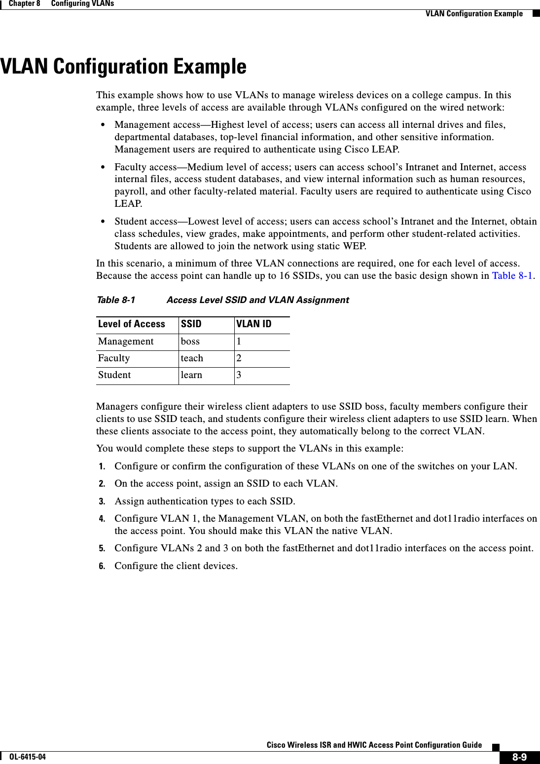
![8-6Cisco Wireless ISR and HWIC Access Point Configuration GuideOL-6415-04Chapter 8 Configuring VLANs Configuring VLANsThis example shows how to: • Name an SSID • Assign the SSID to a VLAN • Enable the VLAN on the radio and Ethernet ports as the native VLANrouter# configure terminalrouter(config)# interface dot11radio0router(config-if)# ssid batmanrouter(config-ssid)# vlan 1router(config-ssid)# exitrouter(config)# interface dot11radio0.1router(config-subif)# encapsulation dot1q 1 nativerouter(config-subif)# exitrouter(config)# interface fastEthernet0.1router(config-subif)# encapsulation dot1q 1 nativerouter(config-subif)# exitrouter(config)# endStep 7 encapsulation dot1q vlan-id [native] Enable a VLAN on the radio interface. (Optional) Designate the VLAN as the native VLAN. On many networks, the native VLAN is VLAN 1.Step 8 exit Return to global configuration mode.Step 9 interface fastEthernet0.x Enter interface configuration mode for the Ethernet VLAN subinterface.Step 10 encapsulation dot1q vlan-id [native]Enable a VLAN on the Ethernet interface. (Optional) Designate the VLAN as the native VLAN. On many networks, the native VLAN is VLAN 1.Step 11 end Return to privileged EXEC mode.Step 12 copy running-config startup-config (Optional) Save your entries in the configuration file.Command Purpose](https://usermanual.wiki/Cisco-Systems/TG2050.Host-System-configuration-guide/User-Guide-1779203-Page-132.png)


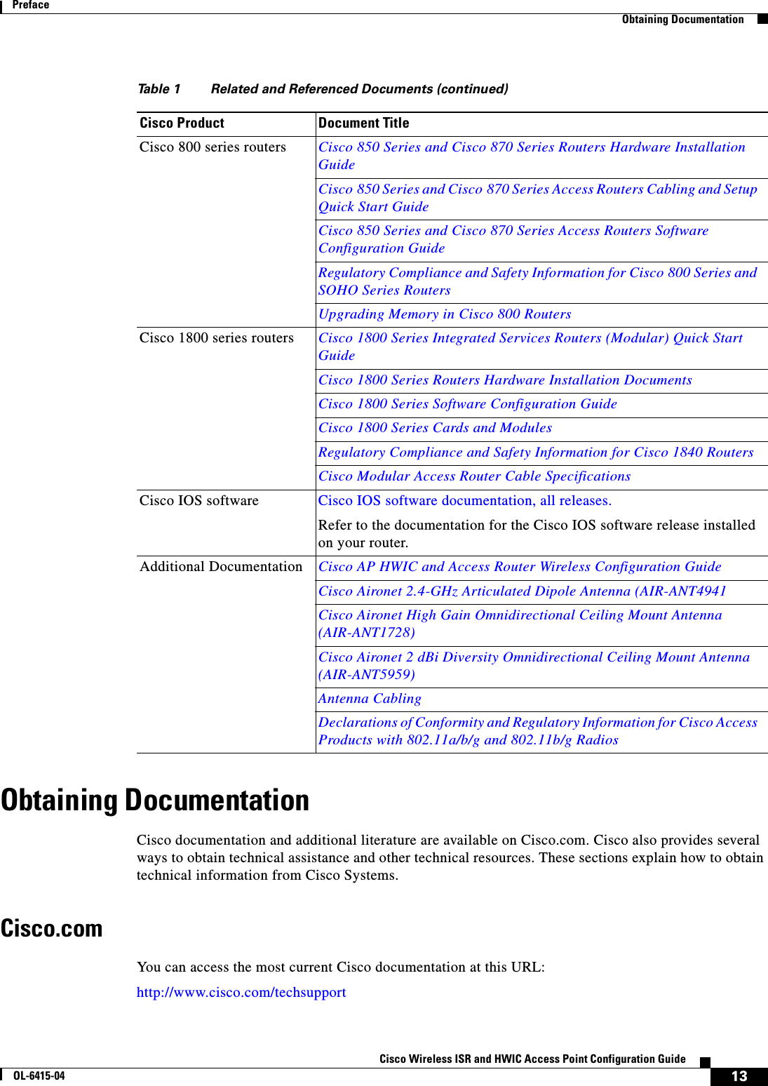
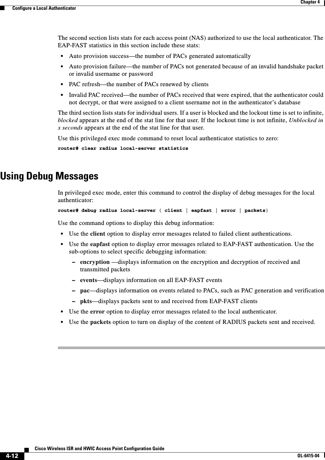
![D-1Cisco Wireless ISR and HWIC Access Point Configuration GuideOL-6415-04APPENDIXDError and Event MessagesThis appendix lists the CLI error and event messages. How to Read System MessagesSystem messages begin with a percent (%) and are structured as follows: The text in bold are required elements of the system message, the text in italics are optional elements of the system message.%FACILITY-SEVERITY-MNEMONIC: Message-textFACILITY is a code consisting of two or more uppercase letters that indicate the facility to which the message refers. A facility can be a hardware device, a protocol, or a module of the system software. You can see a complete list of mainline facility codes for Cisco IOS Release 12.3 on Cisco.com. Go to this URL:http://www.cisco.com/univercd/cc/td/doc/product/software/ios123/123sup/123sems/123semv1/emgover1.htmSEVERITY is a single-digit code from 0 to 7 that reflects the severity of the condition. The lower the number, the more serious the situation. Table D-1 lists the severity levels.MNEMONIC is a code that uniquely identifies the error message.Variable information is indicated in brackets, for example [mac-address] indicates a the mac address of a device, [characters] indicates a character string, and [number] indicates a numeric value.Ta b l e D-1 Error Message Severity LevelsLevel Description0 – emergency System unusable1 – alert Immediate action needed2 – critical Critical condition3 – error Error condition4 – warning Warning condition5 – notification Normal but significant condition6 – informational Informational message only7 – debugging Appears during debugging only](https://usermanual.wiki/Cisco-Systems/TG2050.Host-System-configuration-guide/User-Guide-1779203-Page-157.png)
![D-2Cisco Wireless ISR and HWIC Access Point Configuration GuideOL-6415-04Appendix D Error and Event Messages Message Traceback ReportsMessage Traceback ReportsSome messages describe internal errors and contain traceback reports. This information is very important and should be included when you report a problem to your technical support representative. The following sample message includes traceback information:-Process= “Exec”, level= 0, pid= 17-Traceback= 1A82 1AB4 6378 A072 1054 1860Association Management MessagesError Message DOT11-3-BADSTATE: [mac-address] [chars] [chars] -> [chars]Explanation 802.11 Association and management uses a table-driven state machine to keep track and transition an Association through various states. A state transition occurs when an Association receives one of many possible events. When this error occurs, it means that an Association received an event that it did not expect while in this state.Recommended Action The system can continue but may lose the Association that generates this error. Copy the message exactly as it appears and report it to your technical service representative.Event Message DOT11-6-ASSOC: Interface [interface], Station [char] [mac], SSID [ssid], Authentication Type [auth_type], Key Management [key_mgmt] AssociatedExplanation A station associated to an access point.Recommended Action None.Event Message DOT11-6-ADD: Interface [interface], Station [char] [mac] Associated to parent [char] [mac]Explanation A station associated to an access point.Recommended Action None.Event Message DOT11-6-DISASSOC: Interface [interface], Deauthenticating Station [mac] [char], Reason [explanation], SSID [ssid].Explanation A station disassociated from an access point.Recommended Action None.Error Message DOT11-6-ROAMED: Station [mac-address] Roamed to [mac-address]Explanation The indicated station roamed to the indicated new access point.Recommended Action None.](https://usermanual.wiki/Cisco-Systems/TG2050.Host-System-configuration-guide/User-Guide-1779203-Page-158.png)
![D-3Cisco Wireless ISR and HWIC Access Point Configuration GuideOL-6415-04Appendix D Error and Event Messages 802.11 Subsystem MessagesError Message DOT11-4-ENCRYPT_MISMATCH: Possible encryption key mismatch between interface [interface] and station [mac-address]Explanation The encryption setting of the indicated interface and indicated station may be mismatched. Recommended Action Check the encryption configuration of this interface and the failing station to ensure that the configurations match.802.11 Subsystem MessagesEvent Message DOT11-6-FREQ_INUSE: Radio frequency [int] is in useExplanation When scanning for an unused frequency, the unit recognized another radio using the displayed frequency.Recommended Action None.Event Message DOT11-6-FREQ_USED: Radio frequency [int] selectedExplanation After scanning for an unused frequency, the unit selected the displayed frequency.Recommended Action None.Error Message DOT11-4-NO_VALID_INFRA_SSID: No infrastructure SSID configured. [interface] not startedExplanation No infrastructure SSID was configured and the indicated interface was not started. Recommended Action Add at least one infrastructure SSID to the radio configuration.Error Message DOT11-4-VERSION_UPGRADE: Interface [interface], upgrading radio firmwareExplanation When starting the indicated interface, the access point found the wrong firmware version. The radio will be loaded with the required version.Recommended Action None.Error Message DOT11-2-VERSION_INVALID: Interface [interface], unable to find required radio version [hex].[hex] [number]Explanation When trying to re-flash the radio firmware on the indicated interface, the access point recognized that the indicated radio firmware packaged with the Cisco IOS software had the incorrect version. Recommended Action None.](https://usermanual.wiki/Cisco-Systems/TG2050.Host-System-configuration-guide/User-Guide-1779203-Page-159.png)
![D-4Cisco Wireless ISR and HWIC Access Point Configuration GuideOL-6415-04Appendix D Error and Event Messages 802.11 Subsystem MessagesError Message DOT11-3-RADIO_OVER_TEMPERATURE: Interface [inerface] Radio over temperature detectedExplanation The radio’s internal temperature exceeds maximum limits on the indicated radio interface.Recommended Action Take steps necessary to reduce the internal temperature. These steps will vary based on your specific installation.Error Message DOT11-3-RADIO_TEMPERATURE_NORMAL: Interface [interface] radio temperature returned to normalExplanation The radio’s internal temperature has returned to normal limits on the indicated radio interface.Recommended Action None.Error Message DOT11-3-TX_PWR_OUT_OF_RANGE: Interface [interface] Radio transmit power out of rangeExplanation The transmitter power level is outside the normal range on the indicated radio interface.Recommended Action Remove unit from the network and service.Error Message DOT11-3-RADIO_RF_LO: Interface [interface] Radio cannot lock RF freqExplanation The radio phase lock loop (PLL) circuit is unable to lock the correct frequency on the indicated interface.Recommended Action Remove unit from network and service.Error Message DOT11-3-RADIO_IF_LO: Interface [interface] Radio cannot lock IF freqExplanation The radio intermediate frequency (IF) PLL is unable to lock the correct frequency on the indicated interface.Recommended Action Remove unit from network and service.Error Message DOT11-6-FREQ_SCAN: Interface [interface] Scanning frequencies for [number] secondsExplanation Starting a scan for a least congested frequency on the interface indicated for a the time period indicated.Recommended Action None.](https://usermanual.wiki/Cisco-Systems/TG2050.Host-System-configuration-guide/User-Guide-1779203-Page-160.png)
![D-5Cisco Wireless ISR and HWIC Access Point Configuration GuideOL-6415-04Appendix D Error and Event Messages 802.11 Subsystem MessagesError Message DOT11-2-NO_CHAN_AVAIL: Interface [interface], no channel availableExplanation No frequency is available, likely because RADAR has been detected within the previous 30 minutes.Recommended Action None.Error Message DOT11-6-DFS_SCAN_COMPLETE: DFS scan complete on frequency [frequency] MHzExplanation The device has completed its Dynamic Frequency Scan (DFS) frequency scanning process on the displayed frequency.Recommended Action None.Error Message DOT11-6-DFS_SCAN_START: DFS: Scanning frequency [frequency] MHz for [number] secondsExplanation The device has begun its DFS scanning process.Recommended Action None.Error Message DOT11-6-DFS_TRIGGERED: DFS: triggered on frequency [frequency] MHzExplanation DFS has detected RADAR signals on the indicated frequency.Recommended Action None. The channel will be placed on the non-occupancy list for 30 minutes and a new channel will be selected.Error Message DOT11-4-DFS_STORE_FAIL: DFS: could not store the frequency statisticsExplanation A failure occurred writing the DFS statistics to flash.Recommended Action None.Error Message DOT11-4-NO_SSID: No SSIDs configured, [characters] not startedExplanation All SSIDs were deleted from the configuration. At least one must be configured for the radio to run.Recommended Action Configure at least one SSID on the access point.Error Message DOT11-4-NO_SSID_VLAN: No SSID with VLAN configured. [characters] not startedExplanation No SSID was configured for a VLAN. The indicated interface was not started.Recommended Action At least one SSID must be configured per VLAN. Add at least one SSID for the VLAN on the indicated interface.](https://usermanual.wiki/Cisco-Systems/TG2050.Host-System-configuration-guide/User-Guide-1779203-Page-161.png)
![D-6Cisco Wireless ISR and HWIC Access Point Configuration GuideOL-6415-04Appendix D Error and Event Messages 802.11 Subsystem MessagesError Message DOT11-4-NO_MBSSID_VLAN: No VLANs configured in MBSSID mode. [characters] not startedExplanation No VLAN configured in MBSSID mode. The indicated interface was not started.Recommended Action Add at least one SSID with the VLAN on the indicated interface configuration.Error Message DOT11-4-NO_MBSSID_SHR_AUTH: More than 1 SSID with shared authentication method in non-MBSSID mode. %Explanation Not more than one SSID can have shared authentication method when MBSSID is not enabled.Recommended Action Remove SSID from Dot22Radio radio interface or change authentication mode for SSIC to open configuration.Error Message DOT11-4-FW_LOAD_DELAYED: Interface [interface], network filesys not ready. Delaying firmware [characters] loadExplanation The network filesystem was not running or not ready when trying to flash new firmware into the indicated interface. Loading the identified firmware file has been delayed.Recommended Action Make sure the network is up and ready before attempting to reflash the new firmware.Error Message DOT11-2-FLASH_UNKNOWN_RADIO: Interface [interface] has an unknown radioExplanation The radio type could not be determined when the user attempted to flash new firmware into the indicated interface.Recommended Action Reboot the system and see if the firmware upgrade completes.Error Message DOT11-4-UPLINK_ESTABLISHED: Interface [interface] associated to AP [characters] [characters] [characters]Explanation The indicated repeater has associated to the indicated root access point. Clients can now associate to the indicated repeater and traffic can pass.Recommended Action None.Error Message DOT11-2-UPLINK_FAILED: Uplink to parent failed: [characters]Explanation The connection to the parent access point failed for the displayed reason. The uplink will stop its connection attempts.Recommended Action Try resetting the uplink interface. Contact Technical Support if the problem persists.](https://usermanual.wiki/Cisco-Systems/TG2050.Host-System-configuration-guide/User-Guide-1779203-Page-162.png)
![D-7Cisco Wireless ISR and HWIC Access Point Configuration GuideOL-6415-04Appendix D Error and Event Messages 802.11 Subsystem MessagesError Message DOT11-4-CANT_ASSOC: Interface [interface], cannot associate [characters]Explanation The indicated interface device could not associate to an indicated parent access point.Recommended Action Check the configuration of the parent access point and this unit to make sure there is a match.Error Message DOT11-2-PROCESS_INITIALIZATION_FAILED: The background process for the radio could not be started: [characters]Explanation The initialization process used by the indicated interface failed for some reason, possibly a transient error.Recommended Action Perform a reload of the access point. If this fails to rectify the problem, perform a power cycle. If this still fails, try downgrading the access point firmware to the previous version.Error Message DOT11-2-RADIO_HW_RESET: Radio subsystem is undergoing hardware reset to recover from problemExplanation An unrecoverable error occurred that could not be resolved by a soft reset.Recommended Action None.Error Message DOT11-4-MAXRETRIES: Packet to client [chars] [mac] reached max retries [int], remove the clientExplanation A packet sent to the client has not been successfully delivered many times, and the max retries limit has been reached. The client is deleted from the association table.Recommended Action Force re authentication from the client to reassociate to the router.Error Message DOT11-4-RM_INCAPABLE: Interface [interface]Explanation Indicated interface does not support the radio management feature.Recommended Action None.Error Message DOT11-4-RM_INCORRECT_INTERFACE: Invalid interface, either not existing or non-radioExplanation A radio management request discovered that the interface either does not exist or is not a radio interface.Recommended Action None.](https://usermanual.wiki/Cisco-Systems/TG2050.Host-System-configuration-guide/User-Guide-1779203-Page-163.png)
![D-8Cisco Wireless ISR and HWIC Access Point Configuration GuideOL-6415-04Appendix D Error and Event Messages 802.11 Subsystem MessagesError Message DOT11-3-POWERS_INVALID: Interface [interface], no valid power levels availableExplanation The radio driver found no valid power level settings.Recommended Action Investigate and correct the power source and settings.Error Message DOT11-4-RADIO_INVALID_FREQ: Operating frequency [frequency] invalid - performing a channel scanExplanation The indicated frequency is invalid for operation. A channel scan is being performed to select a valid frequency.Recommended Action None.Error Message DOT11-2-RADIO_INITIALIZATION_ERROR: The radio subsystem could not be initialized [characters]Explanation A critical error was detected while attempting to initialize the radio subsystem.Recommended Action Reload the system.Error Message DOT11-4-UPLINK_NO_ID__PWD: Interface [interface], no username/password supplied for uplink authenticationExplanation The user failed to enter a username and/or password.Recommended Action Enter the username and/or password and try again.Error Message DOT11-4-NO_IE_CFG: No IEs configured for [characters] [ssid index]Explanation When attempting to apply a beacon or probe response to the radio, the beacon or probe was undefined on the indicated SSID index.Recommended Action Check the IE configuration.Error Message DOT11-4-FLASHING_RADIO: Interface [interface], flashing radio firmware [characters]Explanation The indicated interface radio has been stopped to load the indicated new firmware.Recommended Action None.Error Message DOT11-4-LOADING_RADIO: Interface [interface], loading the radio firmware [characters]Explanation The indicated interface radio has been stopped to load new indicated firmware.Recommended Action None.](https://usermanual.wiki/Cisco-Systems/TG2050.Host-System-configuration-guide/User-Guide-1779203-Page-164.png)
![D-9Cisco Wireless ISR and HWIC Access Point Configuration GuideOL-6415-04Appendix D Error and Event Messages 802.11 Subsystem MessagesError Message DOT11-2-NO_FIRMWARE: Interface [interface], no radio firmware file [characters] was found.” Explanation When trying to flash new firmware, the file for the radio was not found in the Flash file system.Recommended Action The wrong image has been loaded into the unit. Locate the correct image based on the type of radio used.Error Message DOT11-2-BAD_FIRMWARE: Interface [interface], radio firmware file [characters] is invalid.”Explanation When trying to Flash new firmware into the indicated interface the indicated radio firmware file was found to be invalid.Recommended Action Make sure the correct firmware image file is located in the place where the unit expects to find it.Error Message DOT11-2-RADIO_FAILED: Interface [interface] failed — [chars]Explanation The radio driver found a severe error and is shutting down.Recommended Action Shut/no shut the interface. If that fails, reboot router.Error Message DOT11-4-FLASH_RADIO_DONE: Interface [interface], flashing radio firmware completedExplanation The indicated interface radio firmware flash is complete, and the radio will be restarted with the new firmware.Recommended Action None.Error Message DOT11-4-UPLINK_DOWN: Interface [interface], parent lost: [characters]Explanation The connection to the parent access point on the indicated interface was lost for the reason indicated. The unit will try to find a new parent access point.Recommended Action None.Error Message DOT11-4-CANT_ASSOC: Cannot associate: [characters]Explanation The unit could not establish a connection to a parent access point for the displayed reason.Recommended Action Veri fy t ha t th e ba si c co nfi g u r a t io n se tt in gs ( SS ID , WE P, an d o th e rs ) o f th e parent access point and this unit match.](https://usermanual.wiki/Cisco-Systems/TG2050.Host-System-configuration-guide/User-Guide-1779203-Page-165.png)
![D-10Cisco Wireless ISR and HWIC Access Point Configuration GuideOL-6415-04Appendix D Error and Event Messages 802.11 Subsystem MessagesError Message DOT11-4-BRIDGE_LOOP: Bridge loop detected between WGB [mac-address] and device [mac-address]Explanation The indicated workgroup bridge reported the address of one of its indicated Ethernet clients and the access point already had that address marked as being somewhere else on the network.Recommended Action Click Refresh on the Associations page on the access point GUI, or enter the clear dot11 statistics command on the CLI.Error Message DOT11-4-ANTENNA_INVALID: Interface [interface], current antenna position not supported, radio disabledExplanation The Indicated AIR-RM21A radio module does not support the high-gain position for the external antenna (the high-gain position is folded flat against the access point). The access point automatically disables the radio when the antenna is in the high-gain position. Recommended Action Fold the antenna on the AIR-RM21A radio module so that it is oriented 90 degrees to the body of the access point.Error Message DOT11-3-RF_LOOPBACK_FAILURE: Interface [interface] Radio failed to pass RF loopback testExplanation Radio loopback test failed for the interface indicated.Recommended Action None.Error Message DOT11-3-RF_LOOPBACK__FREQ_FAILURE: Interface [interface] failed to pass RF loopback testExplanation Radio loopback test failed at a given frequency for the indicated interface.Recommended Action None.Error Message DOT11-7-AUTH_FAILED: Station [mac-address] Authentication failedExplanation The indicated station failed authentication. Recommended Action Verify that the user entered the correct username and password, and verify that the authentication server is online.Error Message DOT11-4-TKIP_MIC_FAILURE: Received TKIP Michael MIC failure report from the station [mac-address] on the packet (TSC=0x%11x) encrypted and protected by [key] key.”Explanation TKIP Michael MIC failure was detected from the indicated station on a unicast frame decrypted locally with the indicated pairwise key. Recommended Action A failure of the Michael MIC in a packet usually indicates an active attack on your network. Search for and remove potential rogue devices from your wireless LAN.](https://usermanual.wiki/Cisco-Systems/TG2050.Host-System-configuration-guide/User-Guide-1779203-Page-166.png)
![D-11Cisco Wireless ISR and HWIC Access Point Configuration GuideOL-6415-04Appendix D Error and Event Messages 802.11 Subsystem MessagesError Message DOT11-4-TKIP_MIC_FAILURE_REPORT: Received TKIP Michael MIC failure report from the station [mac-address] on the packet (TSC=0x0) encrypted and protected by [key] keyExplanation The access point received an EAPOL-key from the indicated station notifying the access point that TKIP Michael MIC failed on a packet transmitted by this access point. Recommended Action None.Error Message DOT11-3-TKIP_MIC_FAILURE_REPEATED: Two TKIP Michael MIC failures were detected within [number] seconds on [interface] interface. The interface will be put on MIC failure hold state for next [number] secondsExplanation Two TKIP Michael MIC failures were detected within the indicated time on the indicated interface. Because this usually indicates an active attack on your network, the interface will be put on hold for the indicated time. During this hold time, stations using TKIP ciphers are disassociated and cannot reassociate until the hold time ends. At the end of the hold time, the interface operates normally. Recommended Action MIC failures usually indicate an active attack on your network. Search for and remove potential rogue devices from your wireless LAN. If this is a false alarm and the interface should not be on hold this long, use the countermeasure tkip hold-time command to adjust the hold time.Error Message SOAP-3-WGB_CLIENT_VLAN: Workgroup Bridge Ethernet client VLAN not configuredExplanation No VLAN is configured for client devices attached to the workgroup bridge.Recommended Action Configure a VLAN to accommodate client devices attached to the workgroup bridge.Error Message SOAP-3-ERROR: Reported on line [number] in file [characters].[characters]Explanation An internal error occurred on the indicated line number in the indicated filename in the controller ASIC.Recommended Action NoneError Message IF-4-MISPLACED_VLAN_TAG: Detected a misplaced VLAN tag on source [interface]. Dropping packetExplanation Received an 802.1Q VLAN tag which could not be parsed correctly. The received packet was encapsulated or de encapsulated incorrectly.Recommended Action](https://usermanual.wiki/Cisco-Systems/TG2050.Host-System-configuration-guide/User-Guide-1779203-Page-167.png)
![D-12Cisco Wireless ISR and HWIC Access Point Configuration GuideOL-6415-04Appendix D Error and Event Messages Local Authenticator MessagesLocal Authenticator MessagesError Message RADSRV-4-NAS_UNKNOWN: Unknown authenticator: [ip-address]Explanation The local RADIUS server received an authentication request but does not recognize the IP address of the network access server (NAS) that forwarded the request.Recommended Action Make sure that every access point on your wireless LAN is configured as a NAS on your local RADIUS server.Error Message RADSRV-4-NAS_KEYMIS: NAS shared key mismatch.Explanation The local RADIUS server received an authentication request but the message signature indicates that the shared key text does not match.Recommended Action Correct the shared key configuration on either the NAS or on the local RADIUS server.Error Message RADSRV-4-BLOCKED: Client blocked due to repeated failed authenticationsExplanation A user failed authentication the number of times configured to trigger a block, and the account been disabled.Recommended Action Use the clear radius local-server user username privileged EXEC command to unblock the user, or allow the block on the user to expire by the configured lockout time.](https://usermanual.wiki/Cisco-Systems/TG2050.Host-System-configuration-guide/User-Guide-1779203-Page-168.png)