Cisco Systems TG2050 802.11 a/b/g/n AP Module User Manual Host system manual
Cisco Systems Inc 802.11 a/b/g/n AP Module Host system manual
UserManual.wiki
>
Cisco Systems
>
TG2050 User Manual
>
Host system manual
Contents
1.
Host System configuration guide
2.
Host system manual
3.
Installation Guide
4.
Host system literature
5.
Host manual part 1
6.
Host manual part 2
Host system manual
Navigation menu
Upload a User Manual
Namespaces
Wiki Guide
HTML
PDF
Info
Views
User Manual
Discussion / Help
Navigation


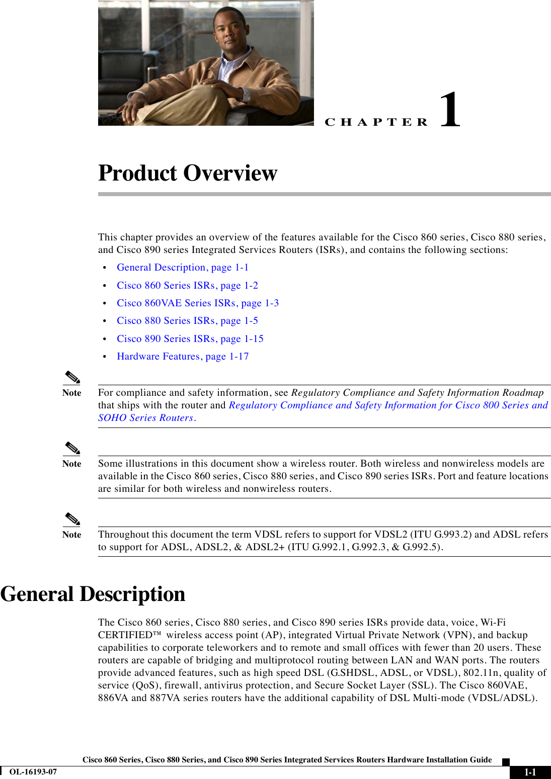
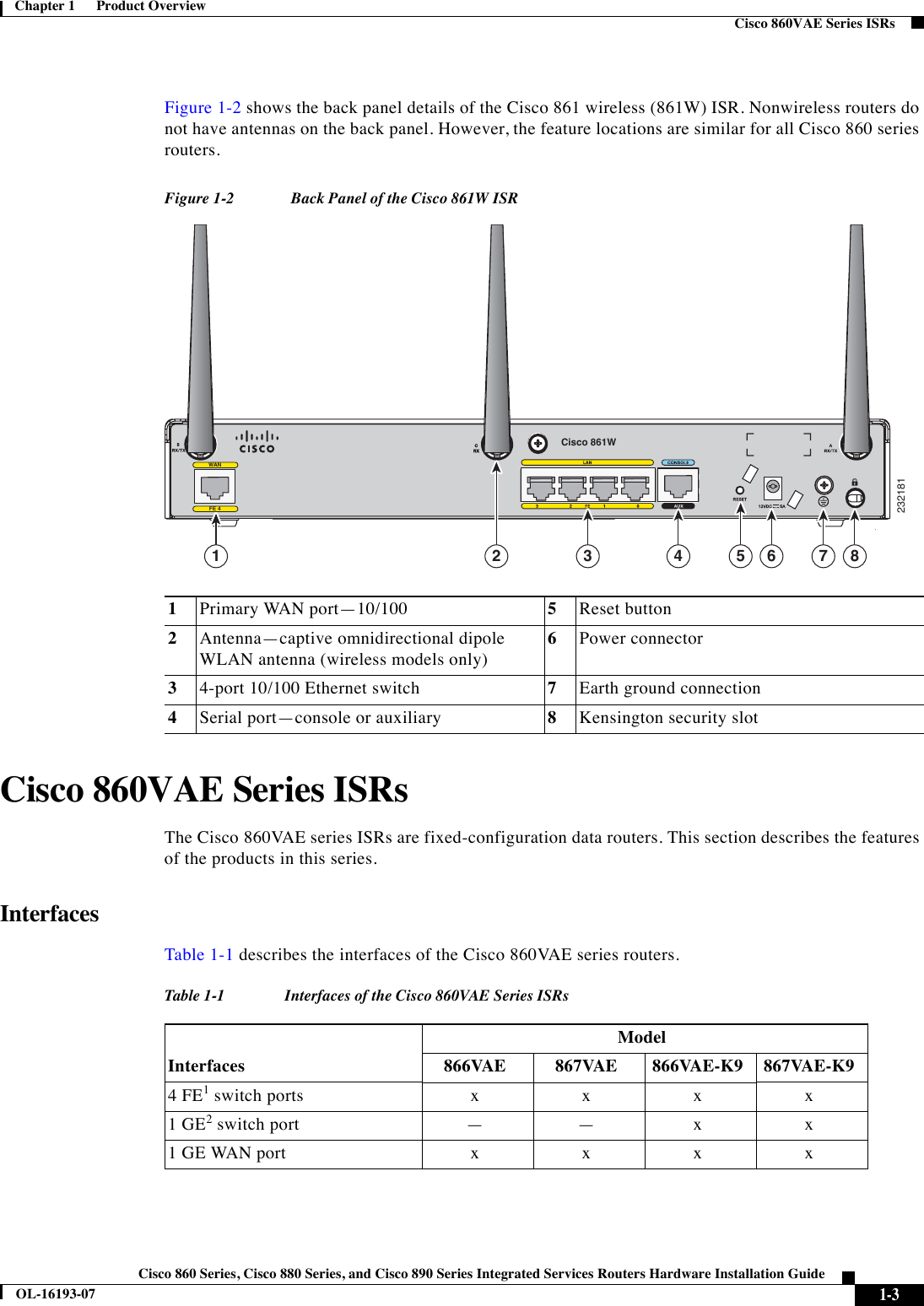

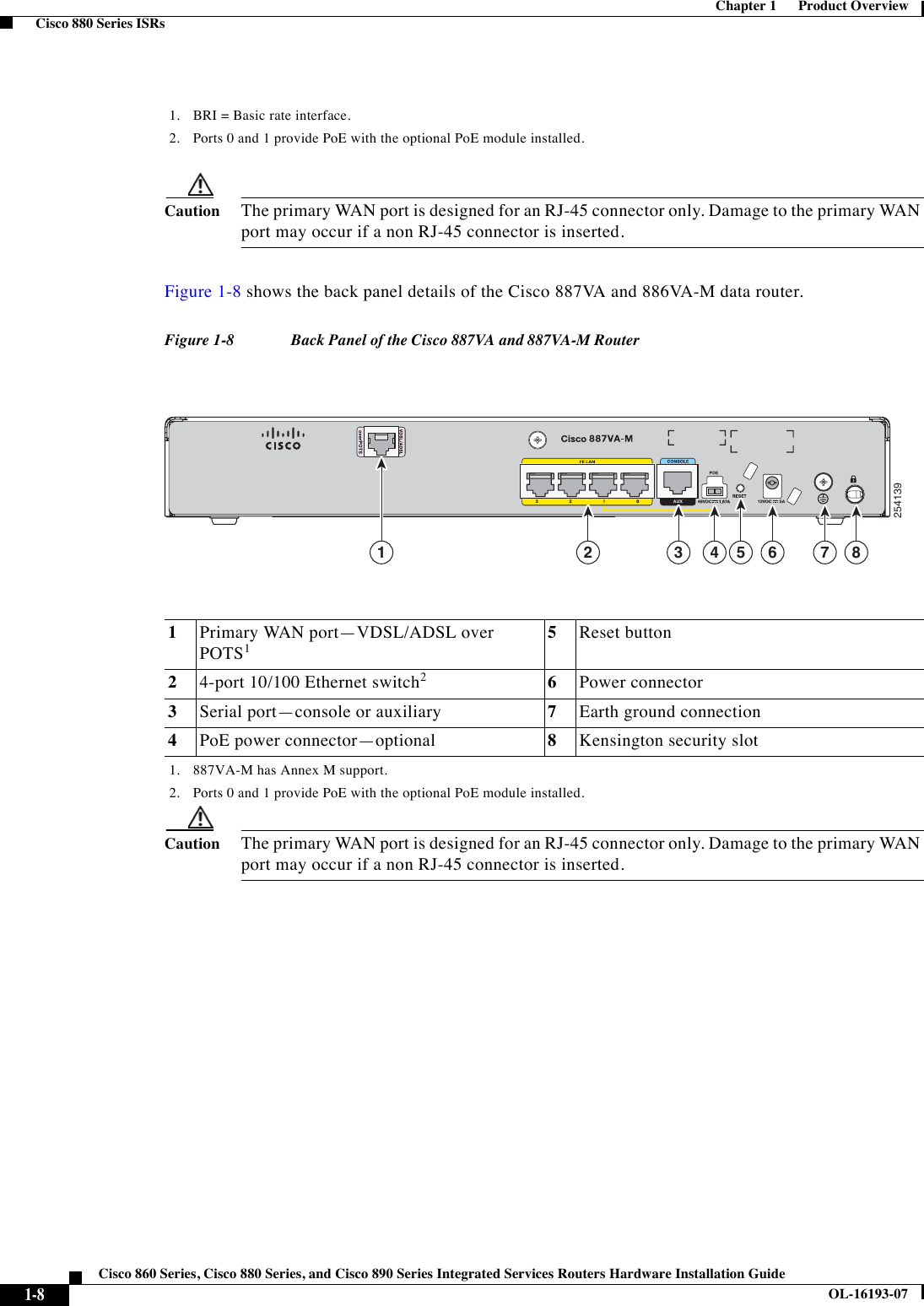
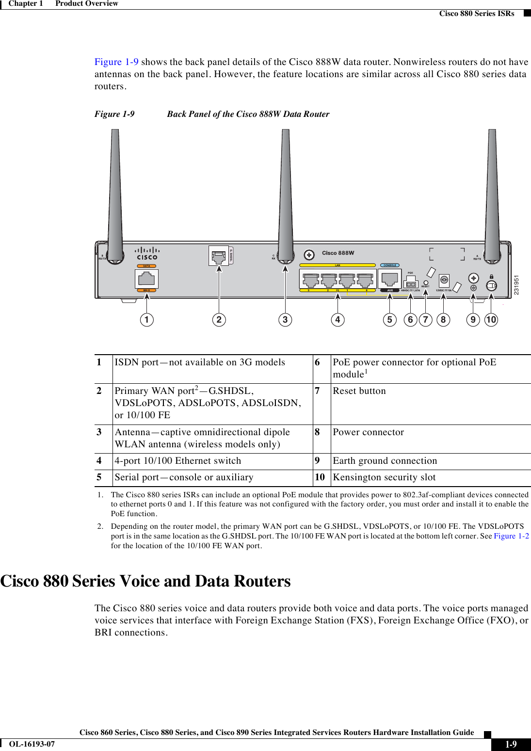
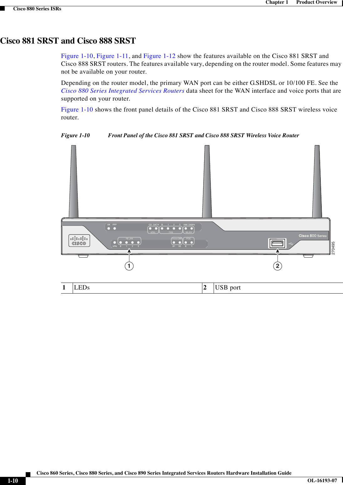
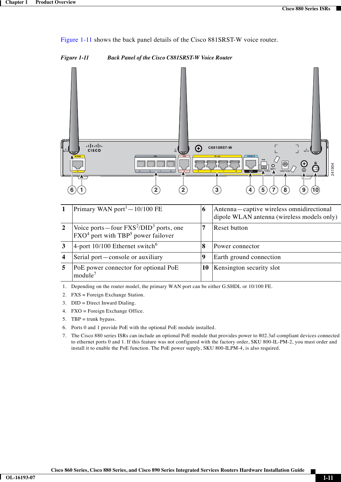
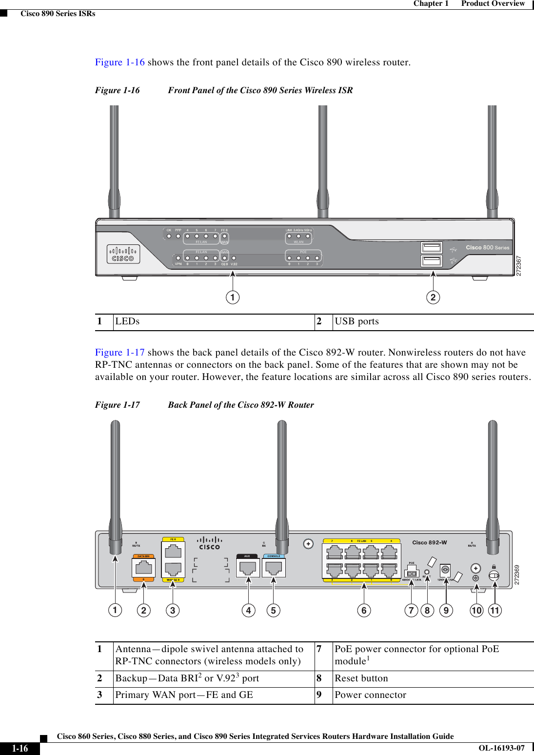
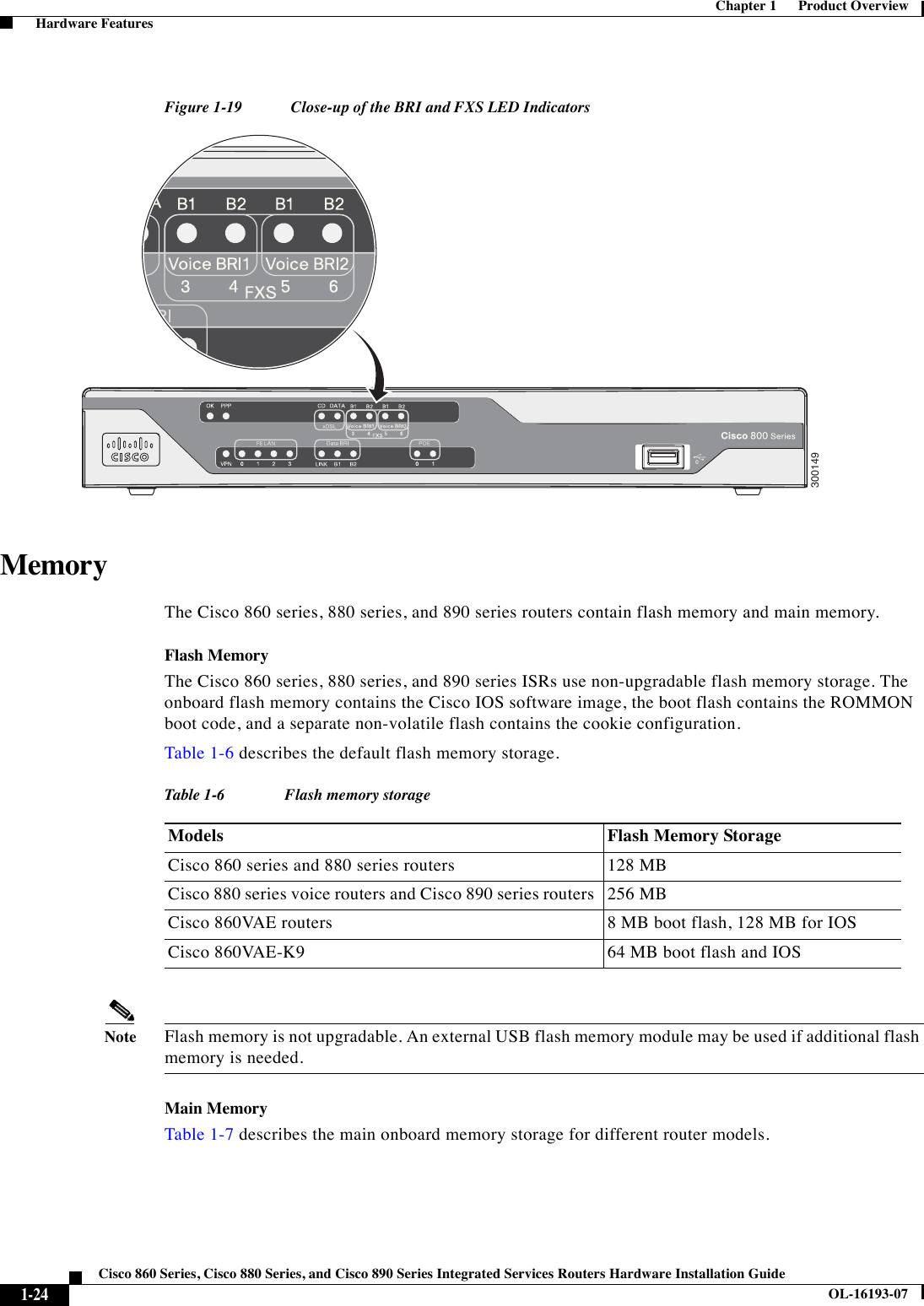
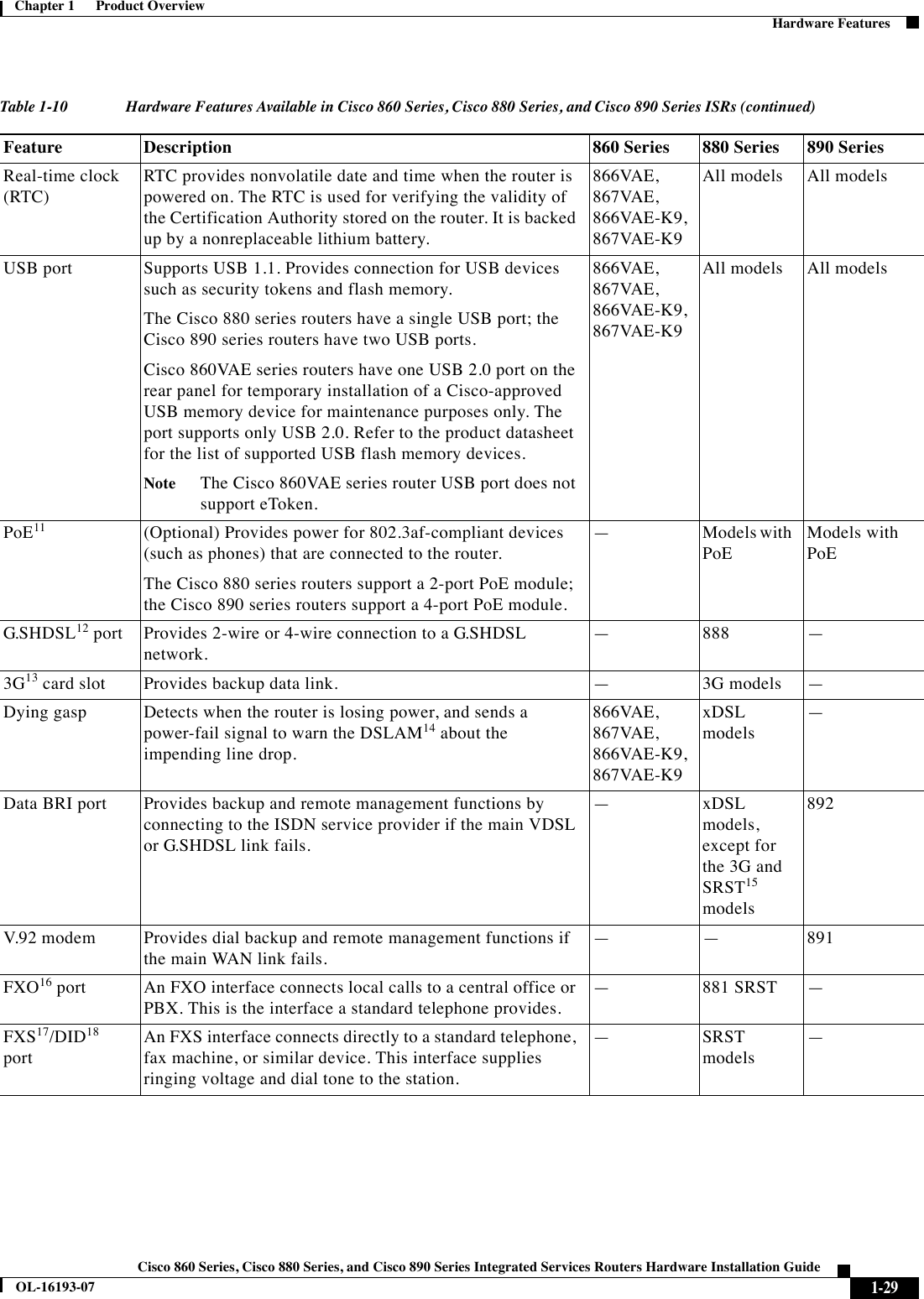
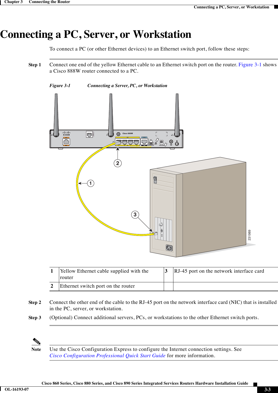
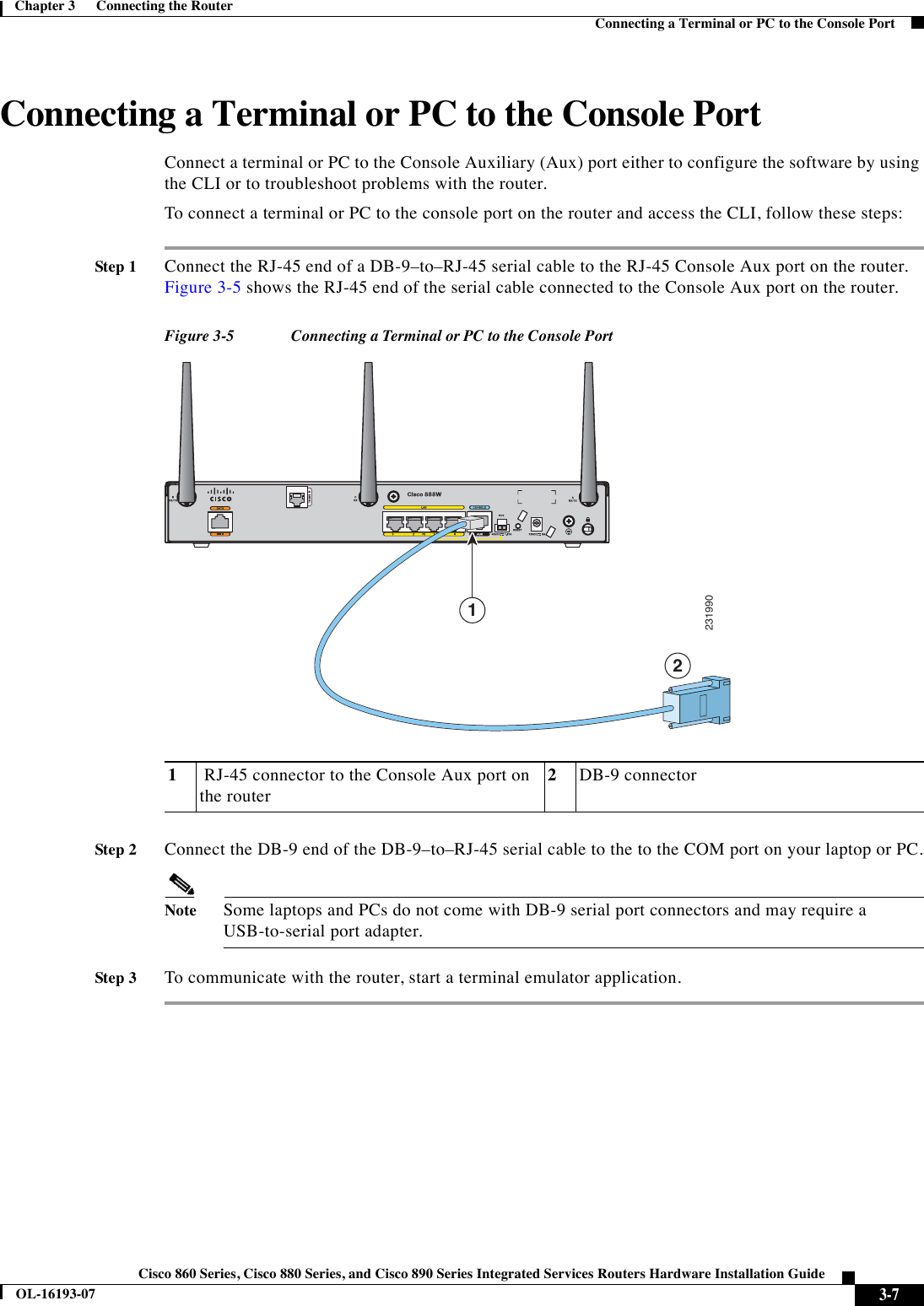
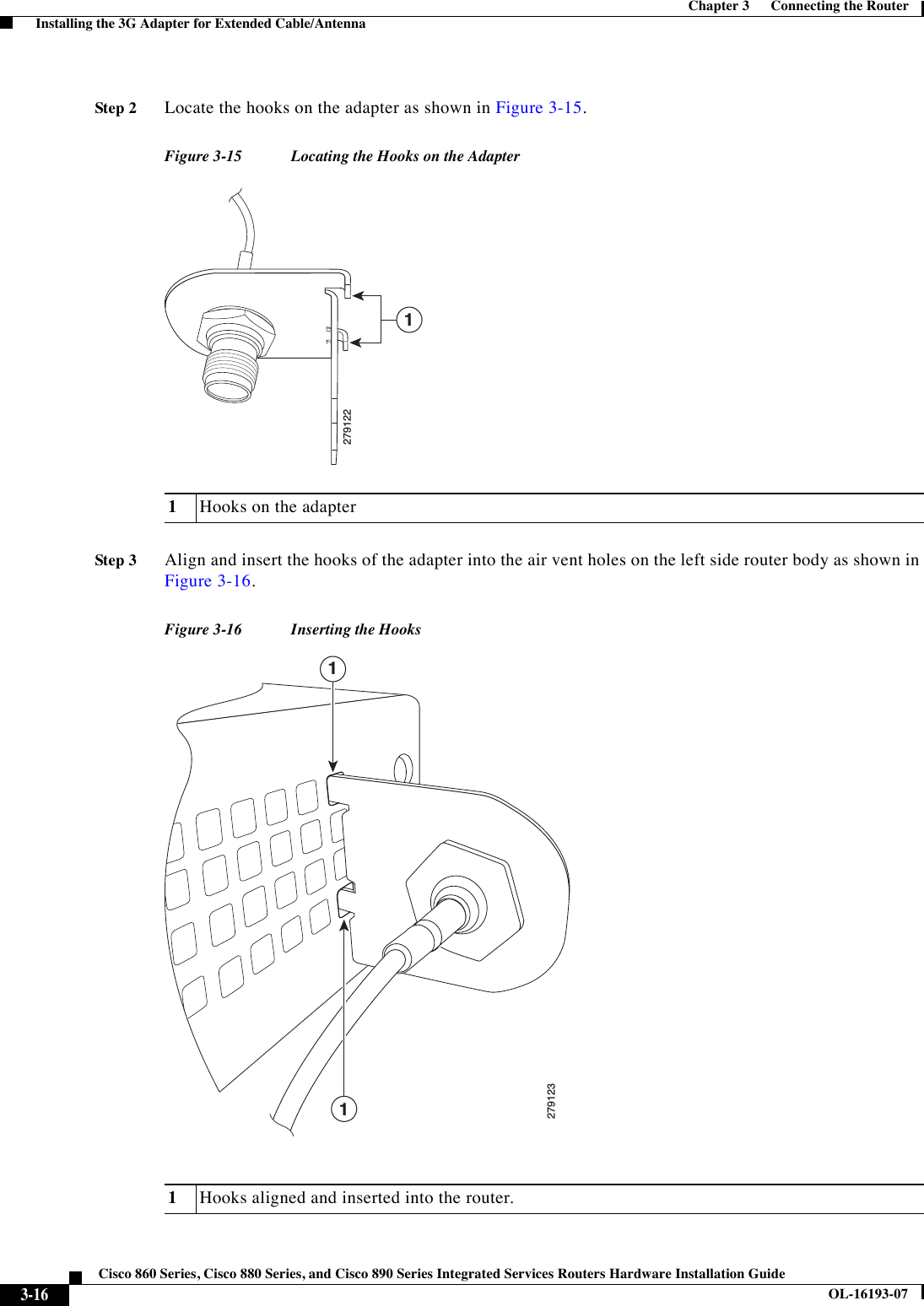
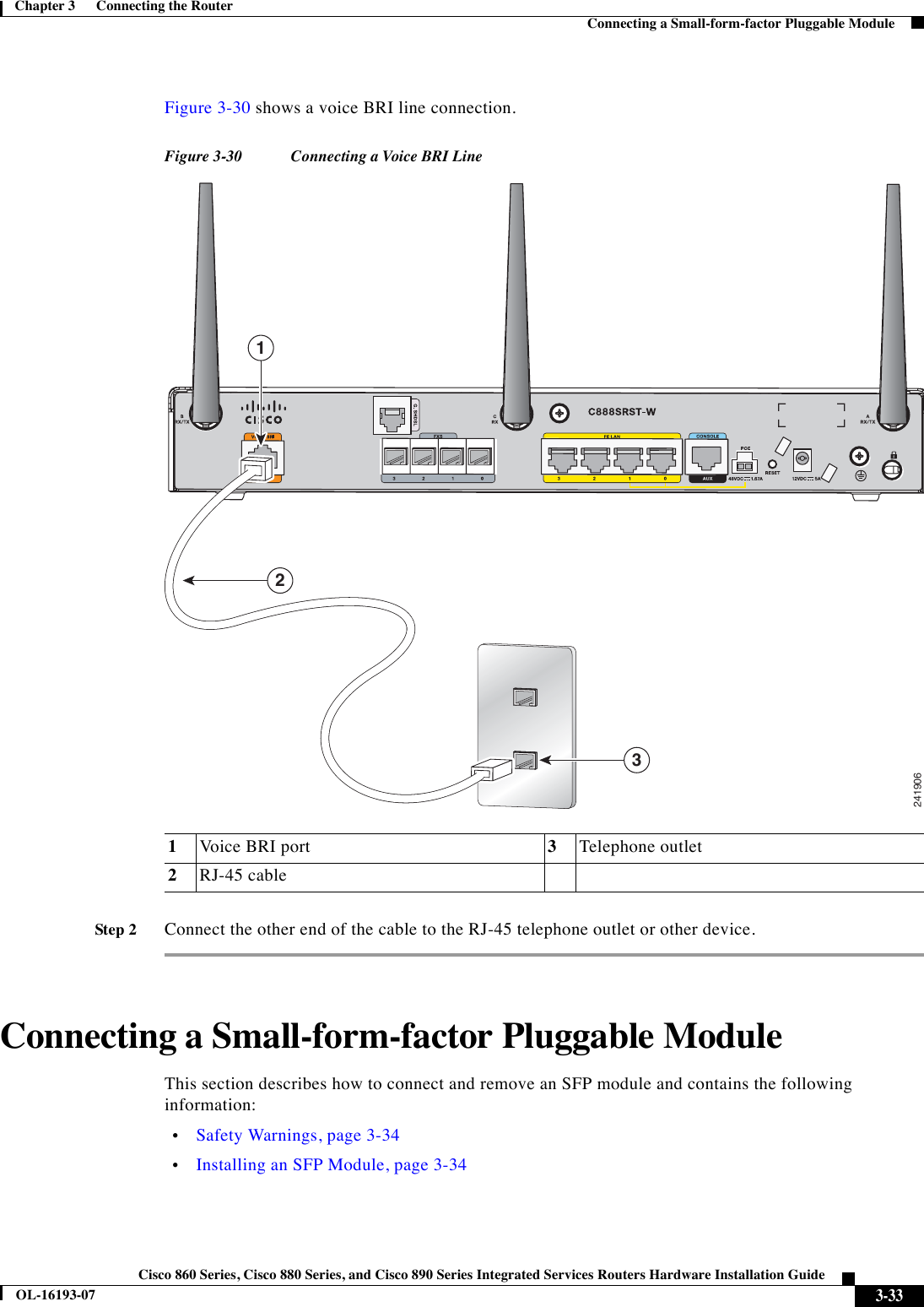
![1-25Cisco 860 Series, Cisco 880 Series, and Cisco 890 Series Integrated Services Routers Hardware Installation GuideOL-16193-07Chapter 1 Product Overview Hardware FeaturesUSB PortThe Cisco 880 series routers have a single Universal Serial Bus (USB 1.1-compliant) port located on the front panel. The USB port provides connection for USB devices such as security tokens and flash memory.The Cisco 890 series routers have two USB 1.1-compliant ports located on the front panel.The Cisco 860VAE series routers have one USB 2.0-compliant port located on the back panel. The Cisco 860VAE series router USB port does not support eToken.FanSome router models do not have a fan, while other models have either one or two fans. The fans spin at full speed, as a diagnostic aid, immediately after the router is powered up. After the router has booted, the fans spin as fast as necessary to minimize fan noise while maintaining a safe internal operating temperature.Power over Ethernet Module The Cisco 880 series ISRs can include an optional Power over Ethernet (PoE) module that provides power to 802.3af-compliant devices connected to FE ports 0 and 1. The Cisco 890 series ISRs can include an optional PoE module that provides power to 802.3af-compliant devices connected to FE ports 0, 1, 2, and 3.The PoE module is an option available only for the Cisco 880 series and 890 series ISRs and requires a 48-V external power adapter.This function can be added to an 880 or 890 series router by installing the PoE adapter card in the router and inserting the PoE 48-V external power adapter.3G Cellular Data WAN ConnectivityThe 3G (Evolution Data Only [EVDO], Universal Mobile Telecommunications Systems [UMTS]) cellular interface is intended for use as a backup data link, but it can also be used as a primary WAN data link. The 3G technology is third-generation wide-area cellular technology that is used in voice telephony and broadband wireless data in a mobile environment. Tabl e 1-7 Main onboard memory storageModels Onboard Memory Storage ExpandibilityCisco 860 series routers 256 MB Not expandableCisco 860VAE series routers 256 MB Not expandableCisco 880 series routers 256 MB (expandable to 768 MB)A memory expansion slot accommodates a PC2-4200, 256-MB or 512-MB double data rate 2 (DDR2) SODIMM, for a maximum of 768 MB.](https://usermanual.wiki/Cisco-Systems/TG2050.Host-system-manual/User-Guide-1779204-Page-39.png)
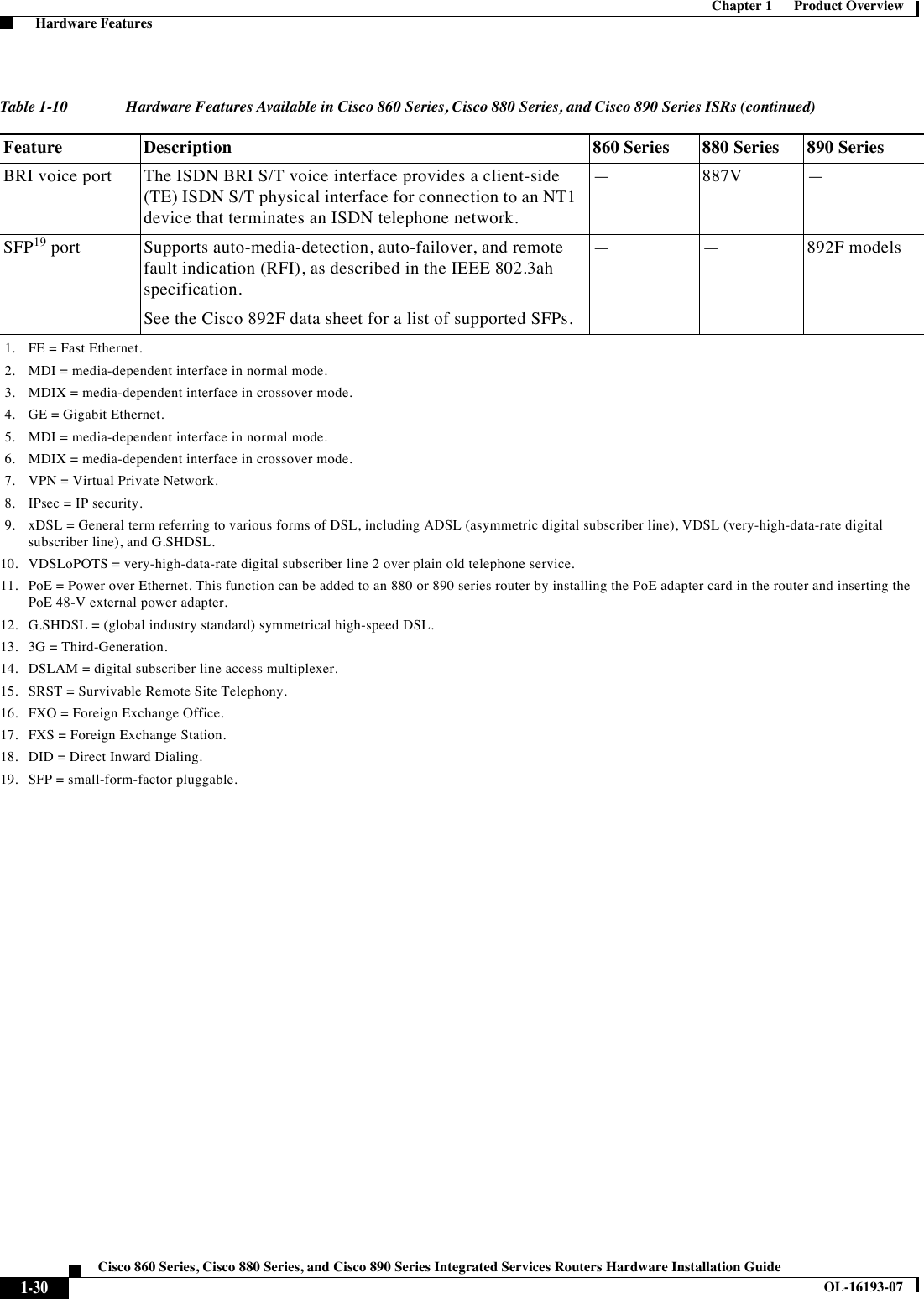
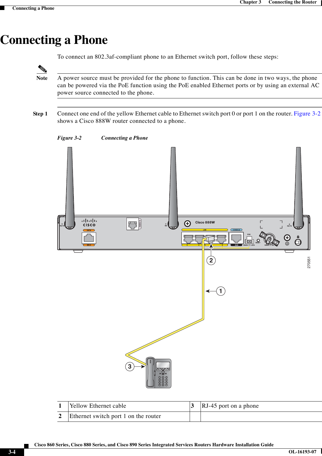
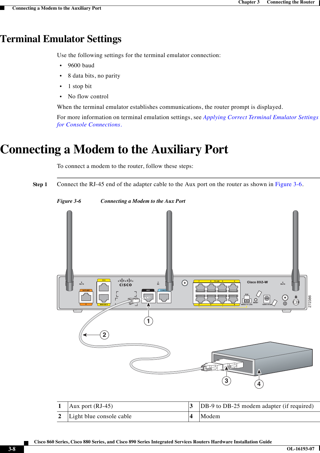
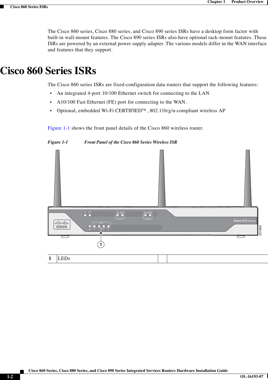
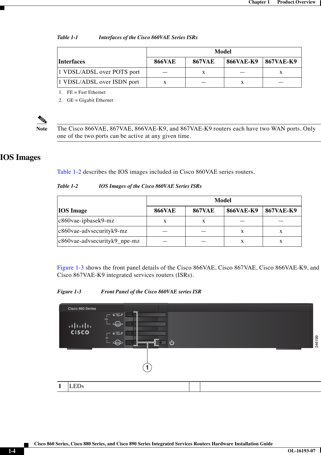
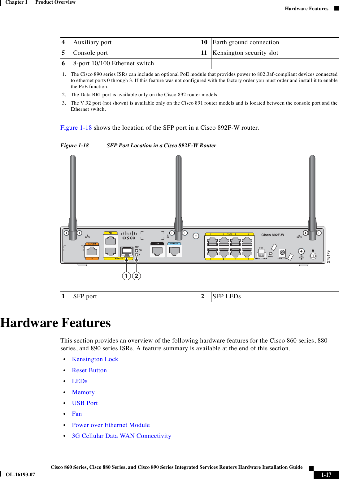
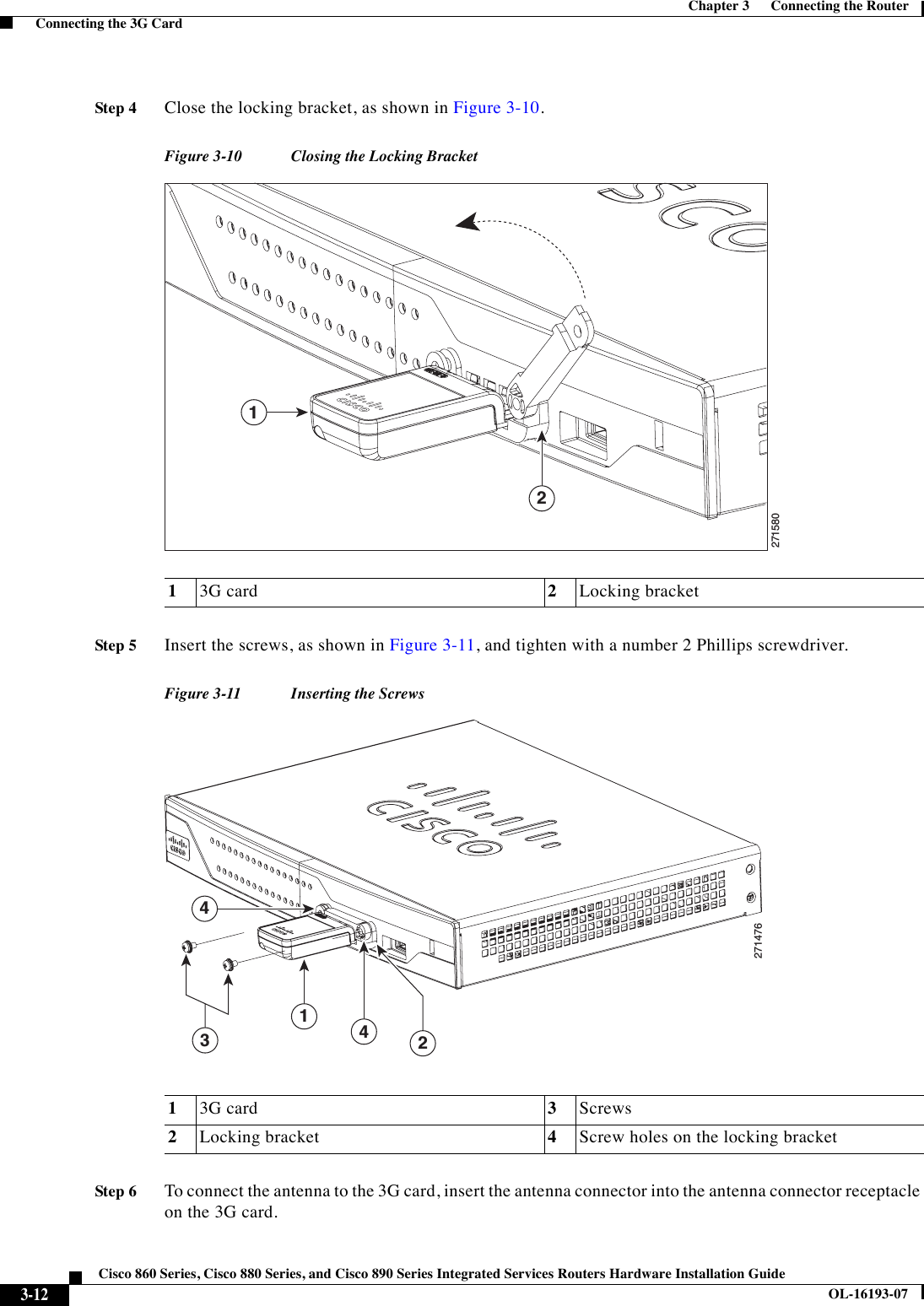
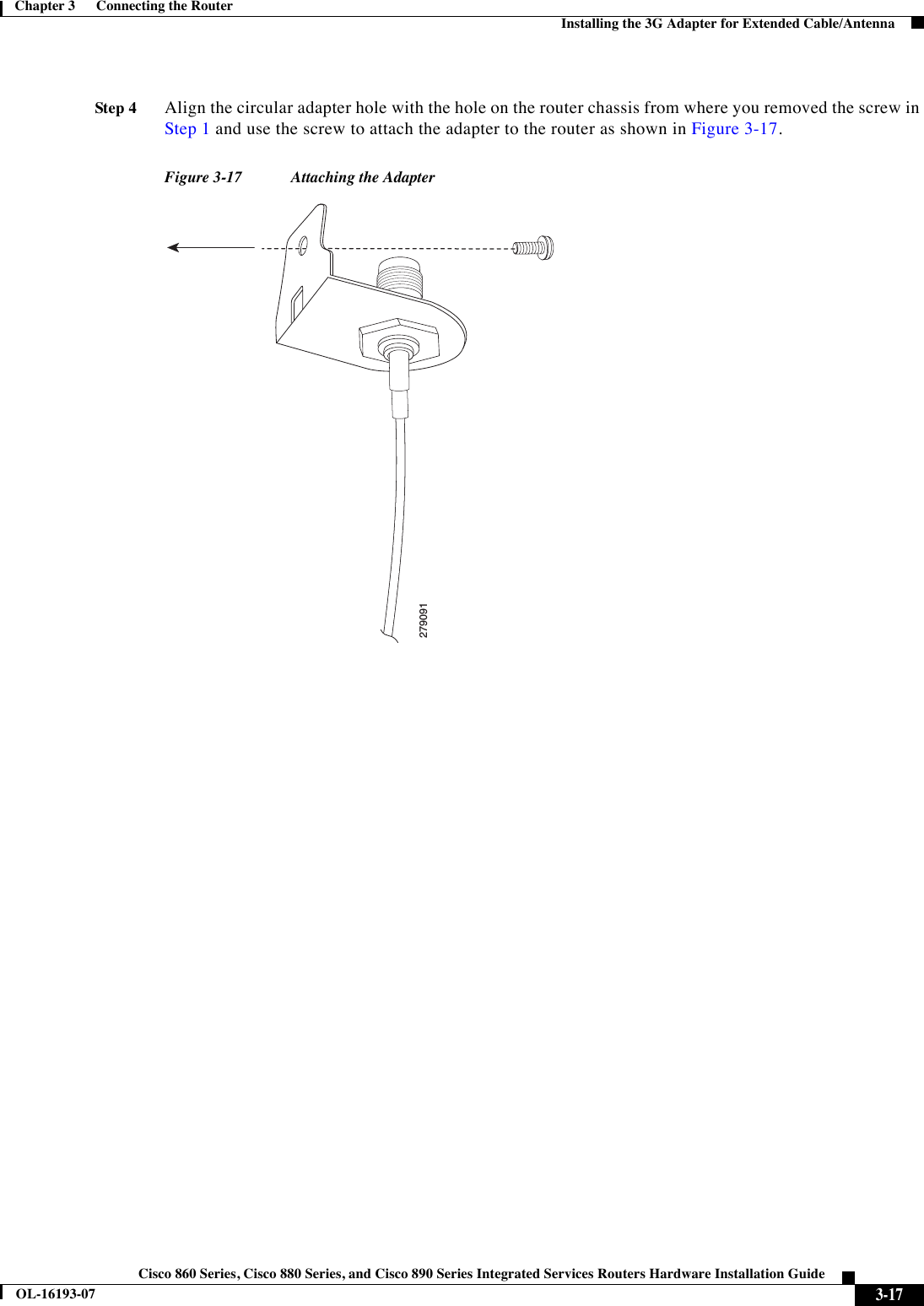
![3-9Cisco 860 Series, Cisco 880 Series, and Cisco 890 Series Integrated Services Routers Hardware Installation GuideOL-16193-07Chapter 3 Connecting the Router Connecting the 3G CardStep 2Connect the DB-9 end of the console cable to the DB-9 end of the modem adapter. Step 3Connect the DB-25 end of the modem adapter to the modem.Step 4Make sure that your modem and the router auxiliary port are configured for the same transmission speed (up to 115200 bits per second [b/s] is supported) and support mode control with data carrier detect (DCD) and data terminal ready (DTR).Connecting the 3G CardNoteThe Cisco 880G router does not support online insertion and removal (OIR) of the third generation (3G)card. You must enter the shutdown command on the cellular interface before you remove the 3G card from the router. To connect and secure the 3G card, follow these steps:Step 1Align the 3G card to the 3G express card slot, as shown in Figure 3-7. Keep the card parallel to the surface and firmly push the card into the slot.TipHolding the 3G card on the flat metal surface makes it easier to align and insert the 3G card.NoteWhen inserting the card into the 3G express card slot, you may hear a metal-on-metal sound as the 3G card rubs against the internal metal cage. The 3G card is designed to fit tightly into the 3G express card slot. Firm pressure may be required to insert the card.NoteGlobal System for Mobile Communications (GSM) customers need to insert a SIM card, provided by their network carrier, into the 3G card.](https://usermanual.wiki/Cisco-Systems/TG2050.Host-system-manual/User-Guide-1779204-Page-65.png)
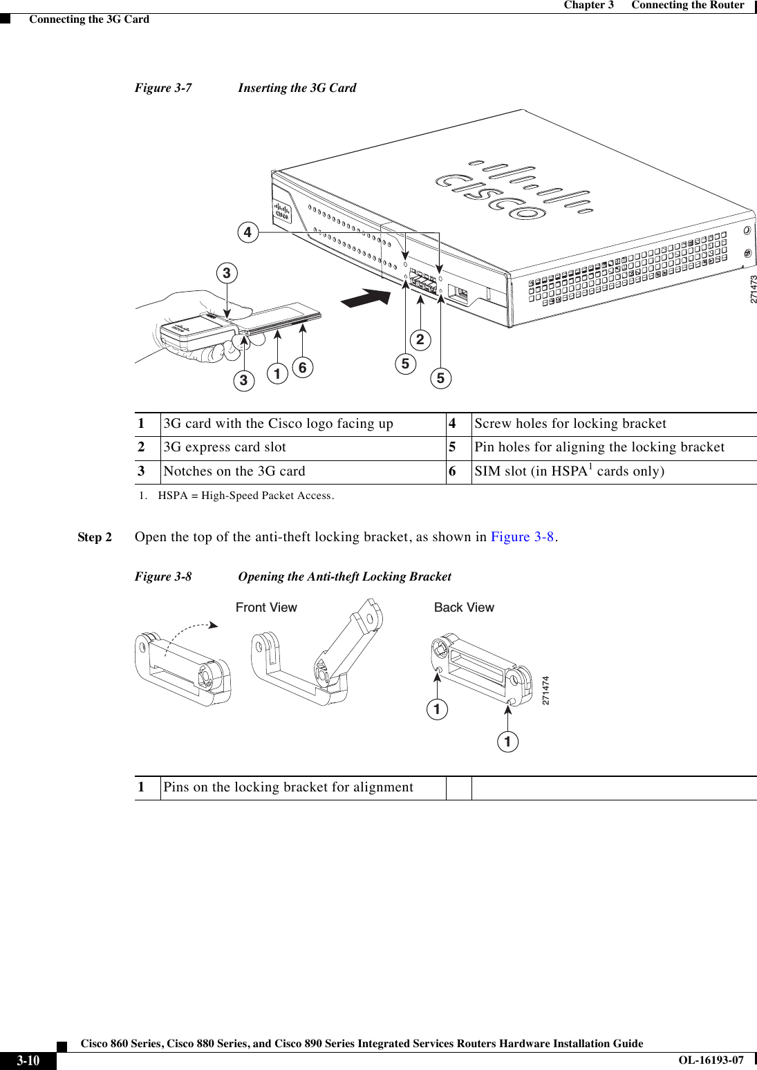
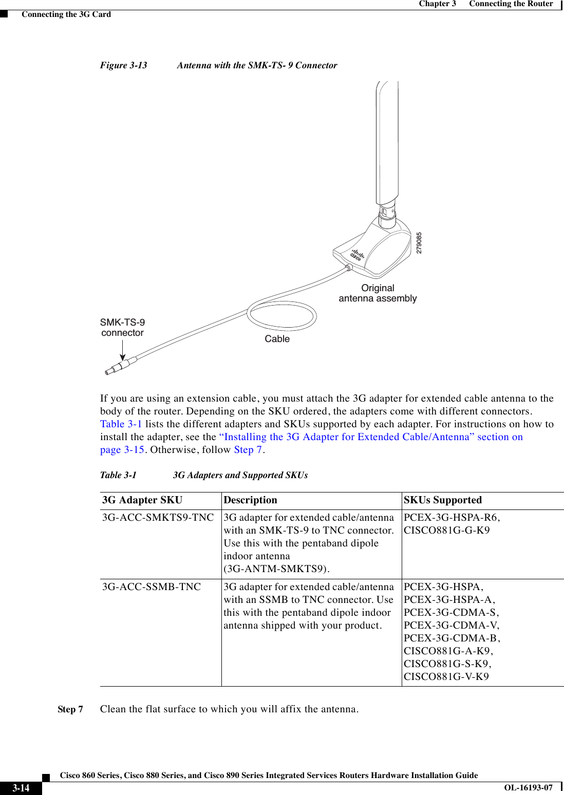
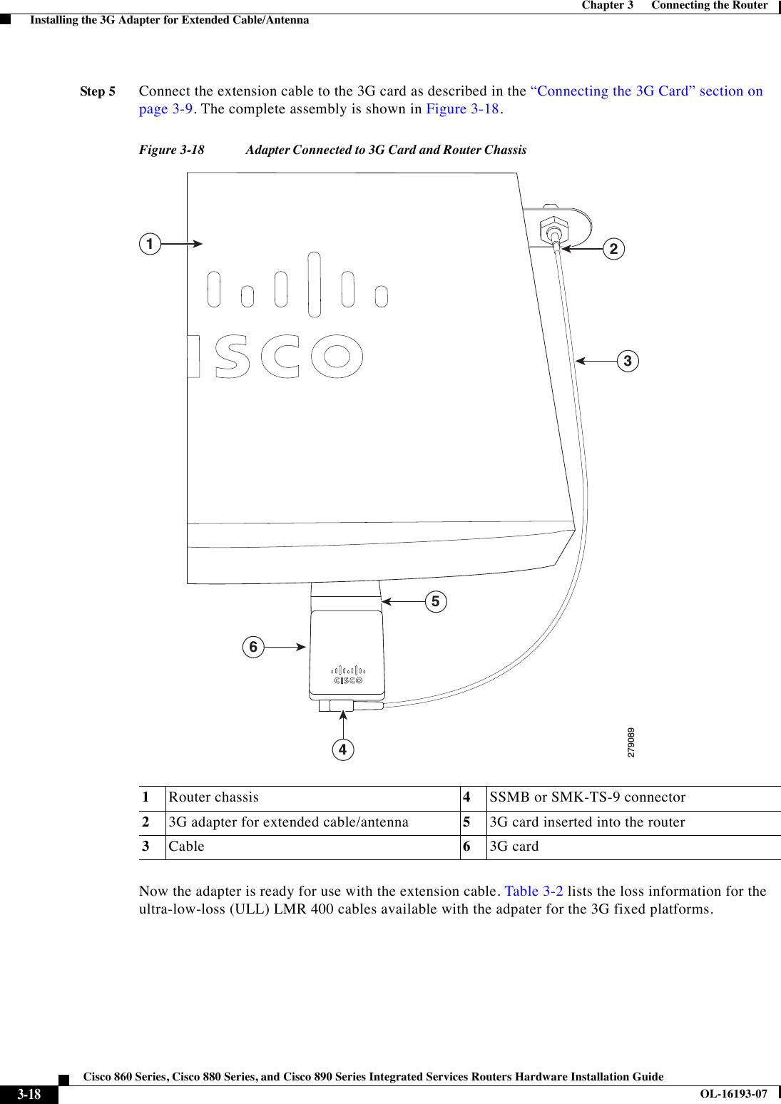
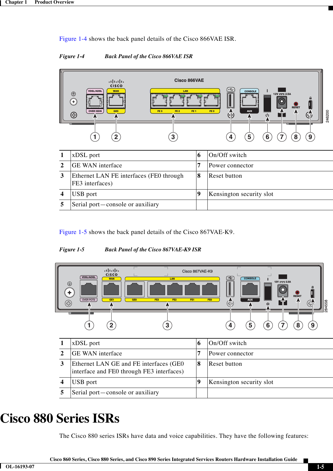
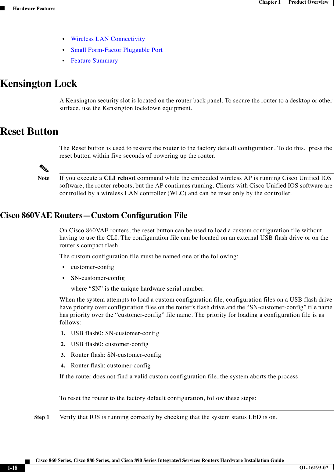
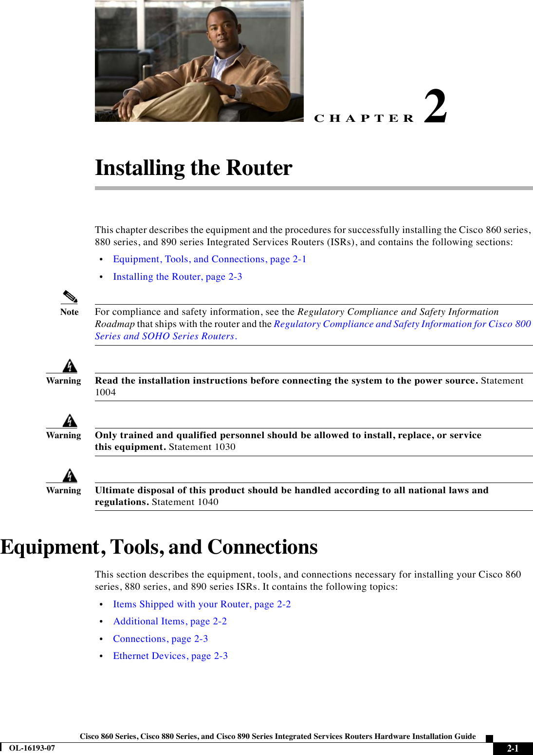
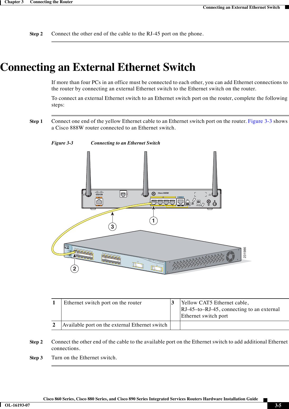
![3-19Cisco 860 Series, Cisco 880 Series, and Cisco 890 Series Integrated Services Routers Hardware Installation GuideOL-16193-07Chapter 3 Connecting the Router Connecting a Data BRI PortFor additional information on all the available cables and antennas available for 3G, go to: http://www.cisco.com/en/US/docs/routers/access/1800/1861/software/feature/guide/mrwlsgsm.html#wp1262730Connecting a Data BRI PortYou can connect the Data BRI port to the ISDN service provider as a backup link to the WAN port in case the primary xDSL (general term referring to various forms of DSL, including global industry standard symmetrical high-speed DSL [G.SHDSL]) WAN service fails. The Data BRI connection is not available on the third-generation (3G) models. The cabling requirements for the ISDN S/T connection are as follows: •You must provide two unshielded Category 5 cables. The first cable connects the NT1 box to the splitter, and the second cable connects the splitter to the wall jack. •There are RJ-45 connectors at both ends of the default orange ISDN S/T cable. However, an RJ-45–to–RJ-11 ISDN S/T cable is available upon request if the wall jack at the site requires an RJ-11 connector. Contact your router reseller for the appropriate cable.CautionBoth LAN and WAN ports use RJ-45 connectors. Use caution when connecting cables to these connectors. To avoid damage to the router, do not connect telephone-network voltage (TNV) circuits (such as ISDN or DSL circuits) to safety extra-low voltage (SELV) circuits (such as LAN circuits). Tabl e 3-2 Cisco Adapter Cables for Use with 3G Fixed Routers Cisco Product NumberAntenna Adapter Length Insertion Loss Frequency (MHz)3G-ACC-SSMB-TNC 14.5 inches 0.66 dB 2100 3G-ACC-TS9-TNC 13.5 inches 0.62 dB 2100](https://usermanual.wiki/Cisco-Systems/TG2050.Host-system-manual/User-Guide-1779204-Page-75.png)

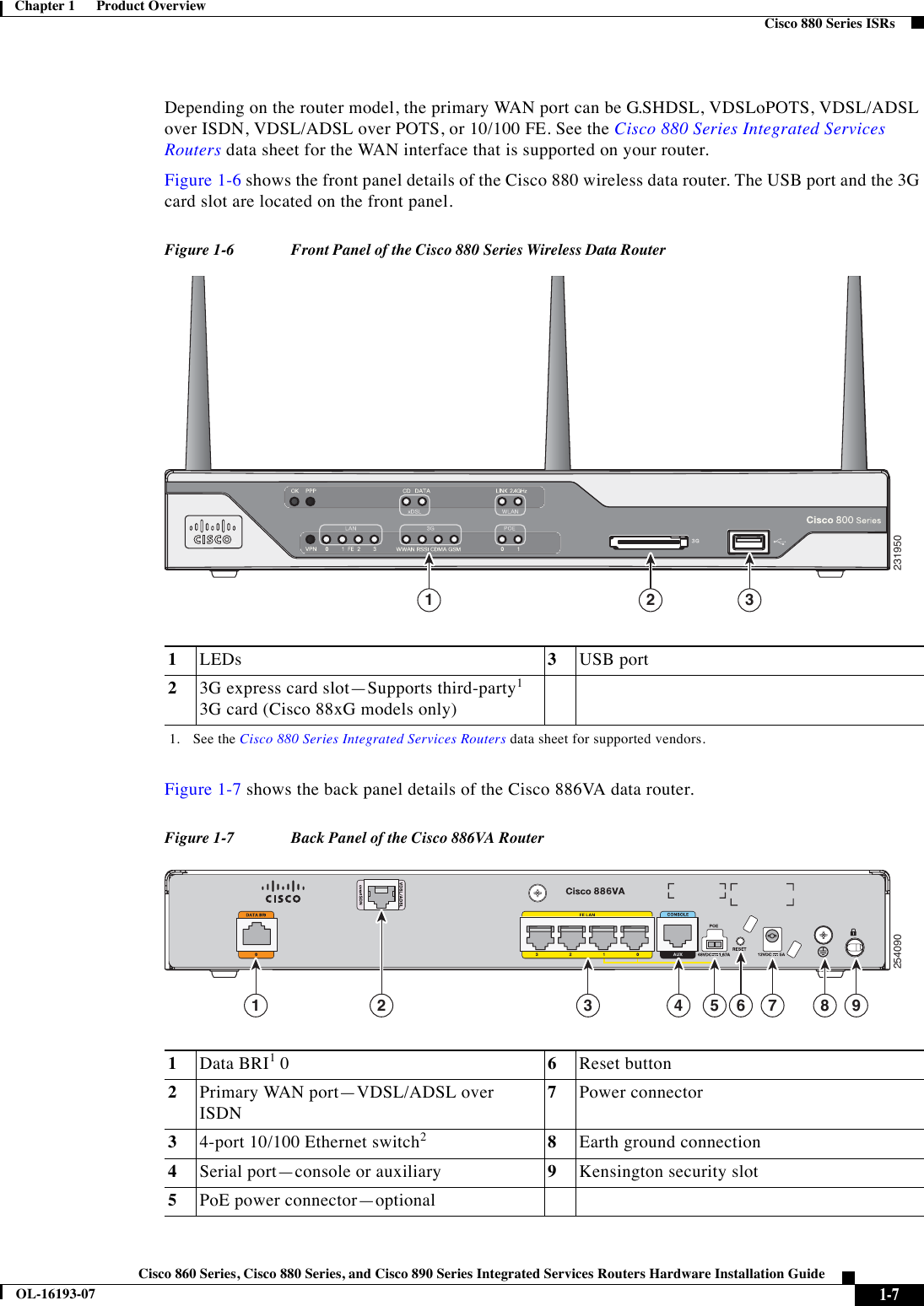
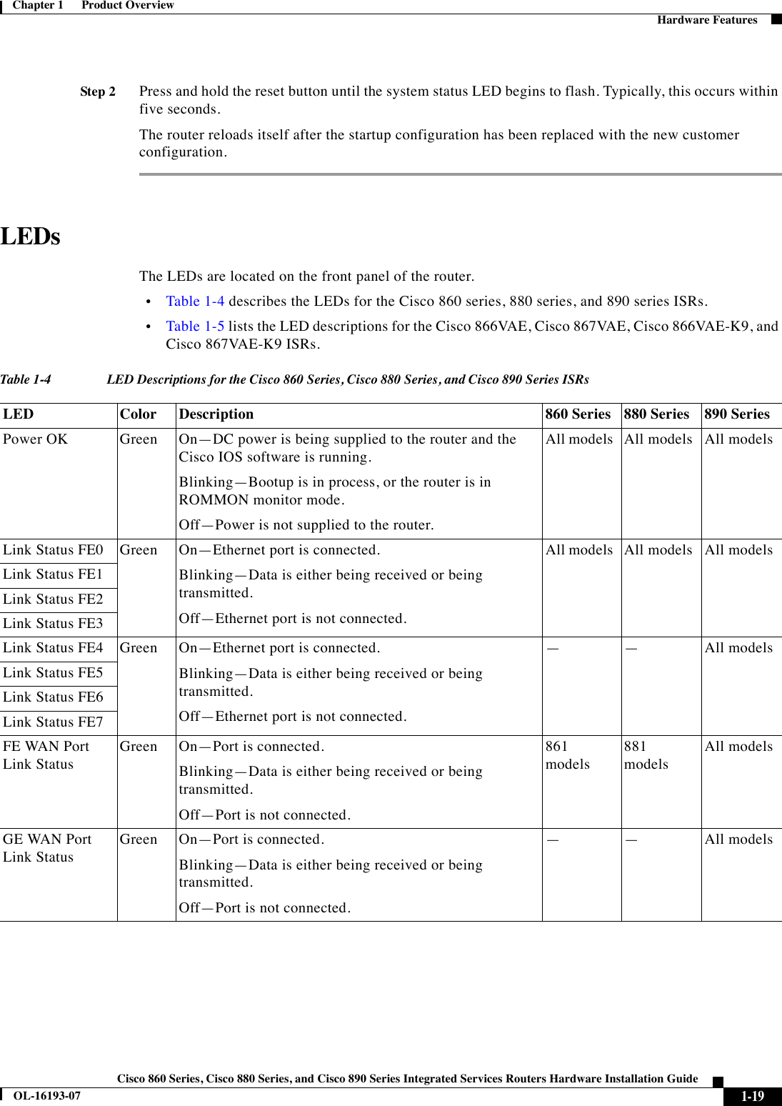
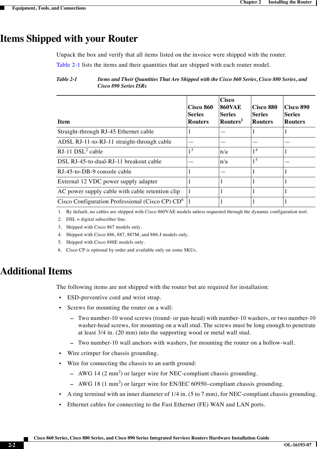
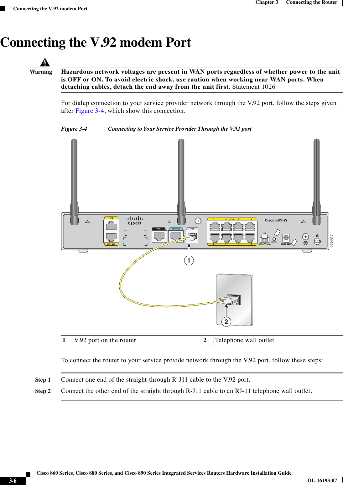
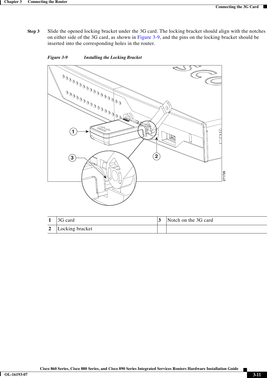
![4-3Cisco 860 Series, Cisco 880 Series, and Cisco 890 Series Integrated Services Routers Hardware Installation GuideOL-16193-07Chapter 4 Initial Configuration Setup Command FacilityNoteSave your configuration changes regularly to avoid losing them during resets, power cycles, or power outages. Use the copy running-config startup-config command at the privileged EXEC mode prompt (Router#) to save the configuration to NVRAM.Step 7Verify the initial configuration. See the “Verifying the Initial Configuration” section on page 4-5.Setup Command FacilityThe setup command facility guides you through the configuration process by prompting you for the specific information that is needed to configure your system. Use the setup command facility to configure a hostname for the router, to set passwords, and to configure an interface for communication with the management network.To use the setup command facility, you must set up a console connection with the router and enter the privileged EXEC mode. NoteFor instructions on how to set up a console connection, see the “Connecting a Terminal or PC to the Console Port” section on page 3-7.To configure the initial router settings by using the setup command facility, follow these steps:Step 1Set up a console connection to your router, and enter privileged EXEC mode. For instructions on how to enter privileged EXEC mode, see Step 1 through Step 4 in the “Cisco IOS CLI” section on page 4-1.Step 2In privileged EXEC mode, at the prompt, enter setup. yourname# setupThe following message is displayed:--- System Configuration Dialog ---Continue with configuration dialog? [yes/no]:You are now in the setup command facility.The prompts in the setup command facility vary, depending on your router model, on the installed interface modules, and on the software image. The following steps and the user entries (in bold) are shown as examples only.NoteIf you make a mistake while using the setup command facility, you can exit and run the setup command facility again. Press Ctrl-C, and enter the setup command at the privileged EXEC mode prompt (Router#). For more information on using the setup command facility, see “The Setup Command” chapter in Cisco IOS Configuration Fundamentals Command Reference, Release 12.2T.Step 3To proceed using the setup command facility, enter yes.Continue with configuration dialog? [yes/no]: yes](https://usermanual.wiki/Cisco-Systems/TG2050.Host-system-manual/User-Guide-1779204-Page-99.png)
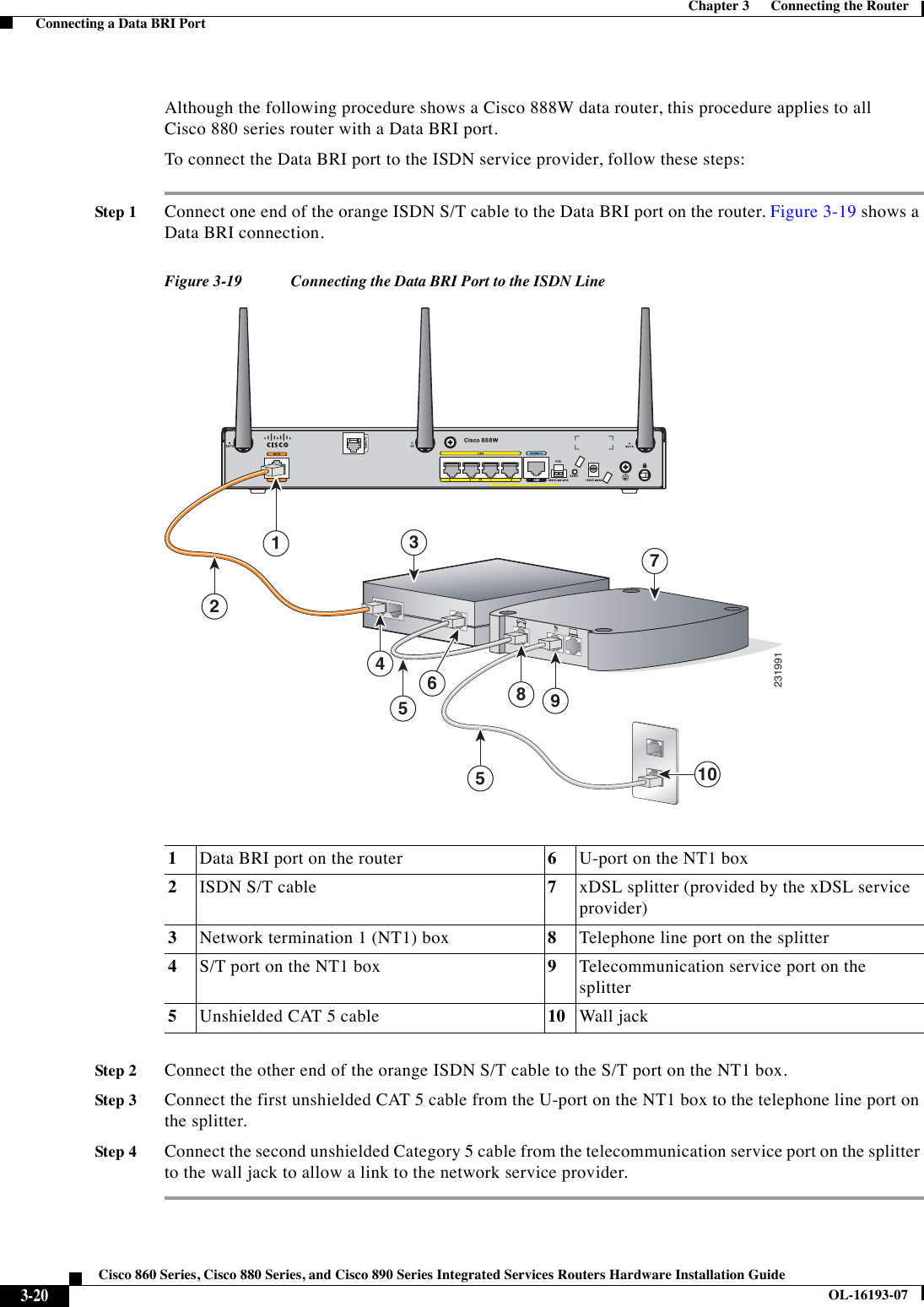
![4-4Cisco 860 Series, Cisco 880 Series, and Cisco 890 Series Integrated Services Routers Hardware Installation GuideOL-16193-07Chapter 4 Initial Configuration Setup Command FacilityStep 4When the following messages appear, enter yes to enter basic management setup.At any point you may enter a question mark '?' for help.Use ctrl-c to abort configuration dialog at any prompt.Default settings are in square brackets '[]'.Basic management setup configures only enough connectivityfor management of the system, extended setup will ask youto configure each interface on the systemWould you like to enter basic management setup? [yes/no]: yesStep 5Enter a hostname for the router (this example uses Router).Configuring global parameters:Enter host name [Router]: RouterStep 6Enter an enable secret password. This password is encrypted (more secure) and cannot be seen when viewing the configuration.The enable secret is a password used to protect access toprivileged EXEC and configuration modes. This password, afterentered, becomes encrypted in the configuration.Enter enable secret: xxxxxxStep 7Enter an enable password that is different from the enable secret password. This password is not encrypted (less secure) and can be seen when viewing the configuration.The enable password is used when you do not specify anenable secret password, with some older software versions, andsome boot images.Enter enable password: xxxxxxStep 8Enter the virtual terminal password, which prevents unauthenticated access to the router through ports other than the console port.The virtual terminal password is used to protectaccess to the router over a network interface.Enter virtual terminal password: xxxxxxStep 9Respond to the following prompts as appropriate for your network.Configure SNMP Network Management? [yes]: Community string [public]:A summary of the available interfaces is displayed.Step 10Choose one of the available interfaces for connecting the router to the management network.Enter interface name used to connect to themanagement network from the above interface summary: fastethernet4Step 11Respond to the following prompts as appropriate for your network.Configuring interface FastEthernet4:Use the 100 Base-TX (RJ-45) connector? [yes]: yesOperate in full-duplex mode? [no]: yesConfigure IP on this interface? [yes]: yes IP address for this interface: 172.1.2.3 Subnet mask for this interface [255.255.0.0] : 255.255.0.0 Class B network is 172.1.0.0, 26 subnet bits; mask is /16The configuration is displayed:The following configuration command script was created:](https://usermanual.wiki/Cisco-Systems/TG2050.Host-system-manual/User-Guide-1779204-Page-100.png)
![4-5Cisco 860 Series, Cisco 880 Series, and Cisco 890 Series Integrated Services Routers Hardware Installation GuideOL-16193-07Chapter 4 Initial Configuration Verifying the Initial Configurationhostname Routerenable secret 5 $1$D5P6$PYx41/lQIASK.HcSbfO5q1enable password xxxxxxline vty 0 4password xxxxxxsnmp-server community public!no ip routing!interface FastEthernet4no shutdownspeed 100duplex autoip address 172.1.2.3 255.255.0.0!Step 12Respond to the following prompts. Enter 2 to save the initial configuration.[0] Go to the IOS command prompt without saving this config.[1] Return back to the setup without saving this config.[2] Save this configuration to nvram and exit.Enter your selection [2]: 2Building configuration...Use the enabled mode 'configure' command to modify this configuration.Press RETURN to get started! RETURNThe user prompt is displayed.Router>Step 13Verify the initial configuration. See the “Verifying the Initial Configuration” section on page 4-5 for verification procedures.After the initial configuration file is created, you can use the Cisco IOS CLI to perform additional configuration. Verifying the Initial ConfigurationTo verify that the new interfaces are operating correctly, perform the following tests: •To verify that the interfaces and line protocol are in the correct state—up or down—enter the show interfaces command. •To display a summary status of the interfaces configured for IP, enter the show ip interface brief command. •To verify that you configured the correct hostname and password, enter the show configuration command.After you complete and verify the initial configuration, you can configure your Cisco router for specific functions.](https://usermanual.wiki/Cisco-Systems/TG2050.Host-system-manual/User-Guide-1779204-Page-101.png)