Cisco Systems TG2050 802.11 a/b/g/n AP Module User Manual Host system manual
Cisco Systems Inc 802.11 a/b/g/n AP Module Host system manual
Contents
Host system manual

Americas Headquarters
Cisco Systems, Inc.
170 West Tasman Drive
San Jose, CA 95134-1706
USA
http://www.cisco.com
Tel: 408 526-4000
800 553-NETS (6387)
Fax: 408 527-0883
Cisco 860 Series, Cisco 880 Series, and Cisco 890
Series Integrated Services Routers Hardware
Installation Guide
Text Part Number: OL-16193-07
THE SPECIFICATIONS AND INFORMATION REGARDING THE PRODUCTS IN THIS MANUAL ARE SUBJECT TO CHANGE WITHOUT NOTICE. ALL
STATEMENTS, INFORMATION, AND RECOMMENDATIONS IN THIS MANUAL ARE BELIEVED TO BE ACCURATE BUT ARE PRESENTED WITHOUT
WARRANTY OF ANY KIND, EXPRESS OR IMPLIED. USERS MUST TAKE FULL RESPONSIBILITY FOR THEIR APPLICATION OF ANY PRODUCTS.
THE SOFTWARE LICENSE AND LIMITED WARRANTY FOR THE ACCOMPANYING PRODUCT ARE SET FORTH IN THE INFORMATION PACKET THAT
SHIPPED WITH THE PRODUCT AND ARE INCORPORATED HEREIN BY THIS REFERENCE. IF YOU ARE UNABLE TO LOCATE THE SOFTWARE LICENSE
OR LIMITED WARRANTY, CONTACT YOUR CISCO REPRESENTATIVE FOR A COPY.
The following information is for FCC compliance of Class A devices: This equipment has been tested and found to comply with the limits for a Class A digital device, pursuant
to part 15 of the FCC rules. These limits are designed to provide reasonable protection against harmful interference when the equipment is operated in a commercial
environment. This equipment generates, uses, and can radiate radio-frequency energy and, if not installed and used in accordance with the instruction manual, may cause
harmful interference to radio communications. Operation of this equipment in a residential area is likely to cause harmful interference, in which case users will be required
to correct the interference at their own expense.
The following information is for FCC compliance of Class B devices: The equipment described in this manual generates and may radiate radio-frequency energy. If it is not
installed in accordance with Cisco’s installation instructions, it may cause interference with radio and television reception. This equipment has been tested and found to
comply with the limits for a Class B digital device in accordance with the specifications in part 15 of the FCC rules. These specifications are designed to provide reasonable
protection against such interference in a residential installation. However, there is no guarantee that interference will not occur in a particular installation.
Modifying the equipment without Cisco’s written authorization may result in the equipment no longer complying with FCC requirements for Class A or Class B digital
devices. In that event, your right to use the equipment may be limited by FCC regulations, and you may be required to correct any interference to radio or television
communications at your own expense.
You can determine whether your equipment is causing interference by turning it off. If the interference stops, it was probably caused by the Cisco equipment or one of its
peripheral devices. If the equipment causes interference to radio or television reception, try to correct the interference by using one or more of the following measures:
• Turn the television or radio antenna until the interference stops.
• Move the equipment to one side or the other of the television or radio.
• Move the equipment farther away from the television or radio.
• Plug the equipment into an outlet that is on a different circuit from the television or radio. (That is, make certain the equipment and the television or radio are on circuits
controlled by different circuit breakers or fuses.)
Modifications to this product not authorized by Cisco Systems, Inc. could void the FCC approval and negate your authority to operate the product.
The Cisco implementation of TCP header compression is an adaptation of a program developed by the University of California, Berkeley (UCB) as part of UCB’s public
domain version of the UNIX operating system. All rights reserved. Copyright © 1981, Regents of the University of California.
NOTWITHSTANDING ANY OTHER WARRANTY HEREIN, ALL DOCUMENT FILES AND SOFTWARE OF THESE SUPPLIERS ARE PROVIDED “AS IS” WITH
ALL FAULTS. CISCO AND THE ABOVE-NAMED SUPPLIERS DISCLAIM ALL WARRANTIES, EXPRESSED OR IMPLIED, INCLUDING, WITHOUT
LIMITATION, THOSE OF MERCHANTABILITY, FITNESS FOR A PARTICULAR PURPOSE AND NONINFRINGEMENT OR ARISING FROM A COURSE OF
DEALING, USAGE, OR TRADE PRACTICE.
IN NO EVENT SHALL CISCO OR ITS SUPPLIERS BE LIABLE FOR ANY INDIRECT, SPECIAL, CONSEQUENTIAL, OR INCIDENTAL DAMAGES, INCLUDING,
WITHOUT LIMITATION, LOST PROFITS OR LOSS OR DAMAGE TO DATA ARISING OUT OF THE USE OR INABILITY TO USE THIS MANUAL, EVEN IF CISCO
OR ITS SUPPLIERS HAVE BEEN ADVISED OF THE POSSIBILITY OF SUCH DAMAGES.
Cisco and the Cisco logo are trademarks or registered trademarks of Cisco and/or its affiliates in the U.S. and other countries. To view a list of Cisco trademarks, go to this
URL: www.cisco.com/go/trademarks. Third-party trademarks mentioned are the property of their respective owners. The use of the word partner does not imply a partnership
relationship between Cisco and any other company. (1110R)
Any Internet Protocol (IP) addresses used in this document are not intended to be actual addresses. Any examples, command display output, and figures included in the
document are shown for illustrative purposes only. Any use of actual IP addresses in illustrative content is unintentional and coincidental.
Cisco 860 Series, Cisco 880 Series, and Cisco 890 Series Integrated Services Routers Hardware Installation Guide
© 2012 Cisco Systems, Inc. All rights reserved.

iii
Cisco 860 Series, Cisco 880 Series, and Cisco 890 Series Integrated Services Routers Hardware Installation Guide
OL-16193-07
Preface
This preface describes the objectives, audience, organization, and conventions of this guide, and
describes related documents that have additional information. It contains the following sections:
•
Objective, page iii
•
Audience, page iii
•
Organization, page iv
•
Conventions, page iv
•
Related Documentation, page xii
•
Obtaining Documentation and Submitting a Service Request, page xii
Objective
This guide provides an overview and explains how to install, connect, and perform initial configuration
for the wireless and nonwireless Cisco 860 series, Cisco 880 series, and Cisco 890 series Integrated
Services Routers (ISRs). Some information may not apply to your particular router model.
For warranty, service, and support information, see the “Cisco One-Year Limited Hardware Warranty
Terms” section in Readme First for the Cisco 800 Series Integrated Services Routers that was shipped
with your router.
Audience
This guide is intended for Cisco equipment providers who are technically knowledgeable and familiar
with Cisco routers and Cisco IOS software and features.
iv
Cisco 860 Series, Cisco 880 Series, and Cisco 890 Series Integrated Services Routers Hardware Installation Guide
OL-16193-07
Preface
Organization
This guide is organized into the following chapters and appendix.
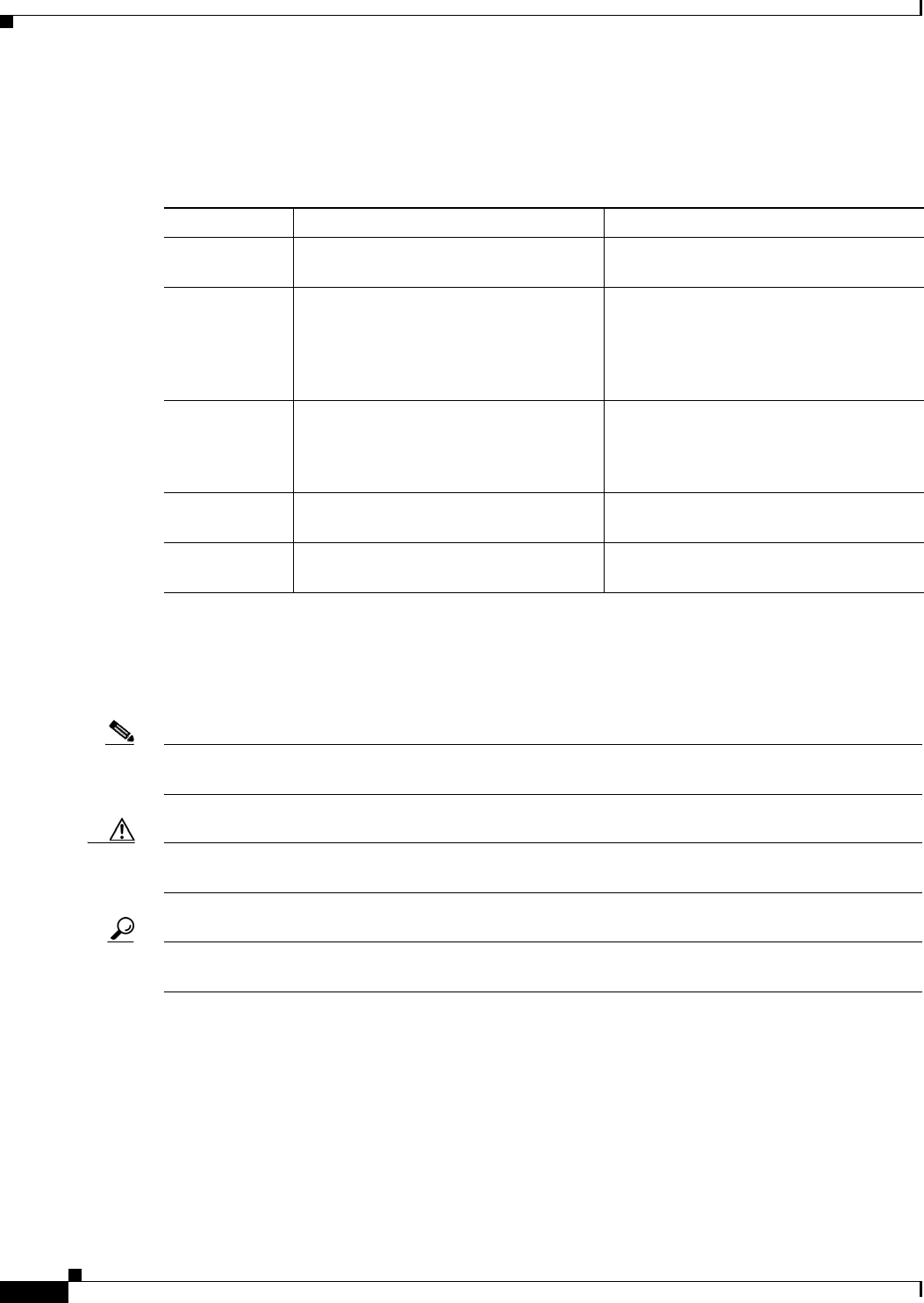
Conventions
This section describes the conventions used in this guide.
Note
Means reader take note. Notes contain helpful suggestions or references to additional information and
material.
Caution
This symbol means reader be careful. In this situation, you might do something that could result in
equipment damage or loss of data.
Tip
Means the following information will help you solve a problem. The tip information might not be
troubleshooting or even an action, but could be useful information.
Chapter Name Description
Chapter 1 Chapter 1, “Product Overview” Describes the router models and the
hardware features available.
Chapter 2 Chapter 2, “Installing the Router” Lists the items shipped with the router, the
equipment and tools necessary for
installing the router, the safety warnings
and guidelines, and the procedures for
installing the router.
Chapter 3 Chapter 3, “Connecting the Router” Describes typical connections for the
router, procedures for connecting the
router to various devices, and how to
verify the connections.
Chapter 4 Chapter 4, “Initial Configuration” Provides the procedures for initially
configuring the router settings.
Appendix A Appendix A, “Technical Specifications” Provides the router, port, and cabling
specifications.

v
Cisco 860 Series, Cisco 880 Series, and Cisco 890 Series Integrated Services Routers Hardware Installation Guide
OL-16193-07
Preface
Warning
IMPORTANT SAFETY INSTRUCTIONS
This warning symbol means danger. You are in a situation that could cause bodily injury. Before
you work on any equipment, be aware of the hazards involved with electrical circuitry and be
familiar with standard practices for preventing accidents. Use the statement number provided
at the end of each warning to locate its translation in the translated safety warnings that
accompanied this device.
Statement 1071
SAVE THESE INSTRUCTIONS
Waarschuwing
BELANGRIJKE VEILIGHEIDSINSTRUCTIES
Dit waarschuwingssymbool betekent gevaar. U verkeert in een situatie die lichamelijk letsel kan
veroorzaken. Voordat u aan enige apparatuur gaat werken, dient u zich bewust te zijn van de
bij elektrische schakelingen betrokken risico's en dient u op de hoogte te zijn van de standaard
praktijken om ongelukken te voorkomen. Gebruik het nummer van de verklaring onderaan de
waarschuwing als u een vertaling van de waarschuwing die bij het apparaat wordt geleverd,
wilt raadplegen.
BEWAAR DEZE INSTRUCTIES
Varoitus
TÄRKEITÄ TURVALLISUUSOHJEITA
Tämä varoitusmerkki merkitsee vaaraa. Tilanne voi aiheuttaa ruumiillisia vammoja. Ennen
kuin käsittelet laitteistoa, huomioi sähköpiirien käsittelemiseen liittyvät riskit ja tutustu
onnettomuuksien yleisiin ehkäisytapoihin. Turvallisuusvaroitusten käännökset löytyvät
laitteen mukana toimitettujen käännettyjen turvallisuusvaroitusten joukosta varoitusten
lopussa näkyvien lausuntonumeroiden avulla.
SÄILYTÄ NÄMÄ OHJEET
Attention
IMPORTANTES INFORMATIONS DE SÉCURITÉ
Ce symbole d'avertissement indique un danger. Vous vous trouvez dans une situation pouvant
entraîner des blessures ou des dommages corporels. Avant de travailler sur un équipement,
soyez conscient des dangers liés aux circuits électriques et familiarisez-vous avec les procédures
couramment utilisées pour éviter les accidents. Pour prendre connaissance des traductions des
avertissements figurant dans les consignes de sécurité traduites qui accompagnent cet appareil,
référez-vous au numéro de l'instruction situé à la fin de chaque avertissement.
CONSERVEZ CES INFORMATIONS
Warnung
WICHTIGE SICHERHEITSHINWEISE
Dieses Warnsymbol bedeutet Gefahr. Sie befinden sich in einer Situation, die zu Verletzungen
führen kann. Machen Sie sich vor der Arbeit mit Geräten mit den Gefahren elektrischer
Schaltungen und den üblichen Verfahren zur Vorbeugung vor Unfällen vertraut. Suchen Sie mit
der am Ende jeder Warnung angegebenen Anweisungsnummer nach der jeweiligen
Übersetzung in den übersetzten Sicherheitshinweisen, die zusammen mit diesem Gerät
ausgeliefert wurden.
BEWAHREN SIE DIESE HINWEISE GUT AUF.

vi
Cisco 860 Series, Cisco 880 Series, and Cisco 890 Series Integrated Services Routers Hardware Installation Guide
OL-16193-07
Preface
Avvertenza
IMPORTANTI ISTRUZIONI SULLA SICUREZZA
Questo simbolo di avvertenza indica un pericolo. La situazione potrebbe causare infortuni alle
persone. Prima di intervenire su qualsiasi apparecchiatura, occorre essere al corrente dei
pericoli relativi ai circuiti elettrici e conoscere le procedure standard per la prevenzione di
incidenti. Utilizzare il numero di istruzione presente alla fine di ciascuna avvertenza per
individuare le traduzioni delle avvertenze riportate in questo documento.
CONSERVARE QUESTE ISTRUZIONI
Advarsel
VIKTIGE SIKKERHETSINSTRUKSJONER
Dette advarselssymbolet betyr fare. Du er i en situasjon som kan føre til skade på person. Før
du begynner å arbeide med noe av utstyret, må du være oppmerksom på farene forbundet med
elektriske kretser, og kjenne til standardprosedyrer for å forhindre ulykker. Bruk nummeret i
slutten av hver advarsel for å finne oversettelsen i de oversatte sikkerhetsadvarslene som fulgte
med denne enheten.
TA VARE PÅ DISSE INSTRUKSJONENE
Aviso
INSTRUÇÕES IMPORTANTES DE SEGURANÇA
Este símbolo de aviso significa perigo. Você está em uma situação que poderá ser causadora de
lesões corporais. Antes de iniciar a utilização de qualquer equipamento, tenha conhecimento
dos perigos envolvidos no manuseio de circuitos elétricos e familiarize-se com as práticas
habituais de prevenção de acidentes. Utilize o número da instrução fornecido ao final de cada
aviso para localizar sua tradução nos avisos de segurança traduzidos que acompanham este
dispositivo.
GUARDE ESTAS INSTRUÇÕES
¡Advertencia!
INSTRUCCIONES IMPORTANTES DE SEGURIDAD
Este símbolo de aviso indica peligro. Existe riesgo para su integridad física. Antes de manipular
cualquier equipo, considere los riesgos de la corriente eléctrica y familiarícese con los
procedimientos estándar de prevención de accidentes. Al final de cada advertencia encontrará
el número que le ayudará a encontrar el texto traducido en el apartado de traducciones que
acompaña a este dispositivo.
GUARDE ESTAS INSTRUCCIONES
Varning!
VIKTIGA SÄKERHETSANVISNINGAR
Denna varningssignal signalerar fara. Du befinner dig i en situation som kan leda till
personskada. Innan du utför arbete på någon utrustning måste du vara medveten om farorna
med elkretsar och känna till vanliga förfaranden för att förebygga olyckor. Använd det nummer
som finns i slutet av varje varning för att hitta dess översättning i de översatta
säkerhetsvarningar som medföljer denna anordning.
SPARA DESSA ANVISNINGAR
vii
Cisco 860 Series, Cisco 880 Series, and Cisco 890 Series Integrated Services Routers Hardware Installation Guide
OL-16193-07
Preface
viii
Cisco 860 Series, Cisco 880 Series, and Cisco 890 Series Integrated Services Routers Hardware Installation Guide
OL-16193-07
Preface
Aviso
INSTRUÇÕES IMPORTANTES DE SEGURANÇA
Este símbolo de aviso significa perigo. Você se encontra em uma situação em que há risco de
lesões corporais. Antes de trabalhar com qualquer equipamento, esteja ciente dos riscos que
envolvem os circuitos elétricos e familiarize-se com as práticas padrão de prevenção de
acidentes. Use o número da declaração fornecido ao final de cada aviso para localizar sua
tradução nos avisos de segurança traduzidos que acompanham o dispositivo.
GUARDE ESTAS INSTRUÇÕES
Advarsel
VIGTIGE SIKKERHEDSANVISNINGER
Dette advarselssymbol betyder fare. Du befinder dig i en situation med risiko for
legemesbeskadigelse. Før du begynder arbejde på udstyr, skal du være opmærksom på de
involverede risici, der er ved elektriske kredsløb, og du skal sætte dig ind i standardprocedurer
til undgåelse af ulykker. Brug erklæringsnummeret efter hver advarsel for at finde
oversættelsen i de oversatte advarsler, der fulgte med denne enhed.
GEM DISSE ANVISNINGER
ix
Cisco 860 Series, Cisco 880 Series, and Cisco 890 Series Integrated Services Routers Hardware Installation Guide
OL-16193-07
Preface
x
Cisco 860 Series, Cisco 880 Series, and Cisco 890 Series Integrated Services Routers Hardware Installation Guide
OL-16193-07
Preface
Warning
When installing the product, please use the provided or designated connection cables/power
cables/AC adaptors. Using any other cables/adaptors could cause a malfunction or a fire.
Electrical Appliance and Material Safety Law prohibits the use of UL-certified cables (that have
the “UL” shown on the code) for any other electrical devices than products designated by CISCO.
The use of cables that are certified by Electrical Appliance and Material Safety Law (that have
“PSE” shown on the code) is not limited to CISCO-designated products.
Statement 371
Warning
There is the danger of explosion if the battery is replaced incorrectly. Replace the battery only
with the same or equivalent type recommended by the manufacturer. Dispose of used batteries
according to the manufacturer’s instructions.
Statement 1015
Warning
Do not use this product near water; for example, near a bath tub, wash bowl, kitchen sink or
laundry tub, in a wet basement, or near a swimming pool.
Statement 1035
Warning
Never install telephone jacks in wet locations unless the jack is specifically designed for
wet locations.
Statement 1036
Warning
Never touch uninsulated telephone wires or terminals unless the telephone line has been
disconnected at the network interface.
Statement 1037
Warning
Avoid using a telephone (other than a cordless type) during an electrical storm. There may be a
remote risk of electric shock from lightning.
Statement 1038

xi
Cisco 860 Series, Cisco 880 Series, and Cisco 890 Series Integrated Services Routers Hardware Installation Guide
OL-16193-07
Preface
Warning
IMPORTANT SAFETY INSTRUCTIONS
This warning symbol means danger. You are in a situation that could cause bodily injury. Before
you work on any equipment, be aware of the hazards involved with electrical circuitry and be
familiar with standard practices for preventing accidents. Use the statement number provided at
the end of each warning to locate its translation in the translated safety warnings that
accompanied this device.
SAVE THESE INSTRUCTIONS.
Statement 1071
Warning
Only trained and qualified personnel should be allowed to install, replace, or service this
equipment.
Statement 1030
Warning
This equipment must be installed and maintained by service personnel as defined by AS/NZS
3260. Incorrectly connecting this equipment to a general-purpose outlet could be hazardous. The
telecommunications lines must be disconnected 1) before unplugging the main power connector
or 2) while the housing is open, or both.
Statement 1043
Warning
Read the installation instructions before connecting the system to the power source.
Statement
1004
Warning
Ultimate disposal of this product should be handled according to all national laws and
regulations.
Statement 1040

xii
Cisco 860 Series, Cisco 880 Series, and Cisco 890 Series Integrated Services Routers Hardware Installation Guide
OL-16193-07
Preface
Related Documentation
In addition to the Cisco 860 series, Cisco 880 series, and Cisco 890 series ISR Hardware Installation
Guide (this document), the Cisco 860 series, Cisco 880 series, and Cisco 890 series ISR documentation
set includes the following documents:
•
Regulatory Compliance and Safety Information for Cisco 800 Series and SOHO Series Routers
•
Cisco 860 Series, Cisco 880 Series, and Cisco 890 Series Integrated Services Routers Software
Configuration Guide
•
Software Activation on Cisco Integrated Services Routers and Cisco Integrated Service Routers G2
•
Cisco IOS Software Activation Configuration Guide
•
Declarations of Conformity and Regulatory Information for Cisco Access Products with 802.11a/b/g
and 802.11b/g Radios
•
Cisco IOS Release Notes
•
Cisco IOS Quality of Service Solutions Command Reference, Release 12.4T
•
Cisco IOS Security Configuration Guide, Release 12.4T
•
Cisco IOS Security Command Reference, Release 12.4T
•
Cisco IOS Command Reference for Cisco Aironet Access Points and Bridges, versions 12.4(10b) JA
and 12.3(8) JEC
•
Wireless LAN Controllers
•
Unified Wireless LAN Access Points
•
Cisco IOS Voice Port Configuration Guide
•
SCCP Controlled Analog (FXS) Ports with Supplementary Features in Cisco IOS Gateways
•
Cisco CP Express User’s Guide
Searching Cisco Documents
To search a HTML document using a web browser, press Ctrl-F (Windows) or Cmd-F (Apple). In most
browsers, the option to search whole words only, invoke case sensitivity, or search forward and
backward is also available.
To search a PDF document in Adobe Reader, use the basic Find toolbar (Ctrl-F) or the Full Reader
Search window (Shift-Ctrl-F). Use the Find toolbar to find words or phrases within a specific document.
Use the Full Reader Search window to search multiple PDF files simultaneously and to change case
sensitivity and other options. Adobe Reader’s online help has more information about how to search
PDF documents.
Obtaining Documentation and Submitting a Service Request
For information on obtaining documentation, submitting a service request, and gathering additional
information, see the monthly What’s New in Cisco Product Documentation, which also lists all new and
revised Cisco technical documentation, at:
http://www.cisco.com/en/US/docs/general/whatsnew/whatsnew.html

xiii
Cisco 860 Series, Cisco 880 Series, and Cisco 890 Series Integrated Services Routers Hardware Installation Guide
OL-16193-07
Preface
Subscribe to the What’s New in Cisco Product Documentation as a Really Simple Syndication (RSS) feed
and set content to be delivered directly to your desktop using a reader application. The RSS feeds are a free
service and Cisco currently supports RSS version 2.0.

xiv
Cisco 860 Series, Cisco 880 Series, and Cisco 890 Series Integrated Services Routers Hardware Installation Guide
OL-16193-07
Preface

CHAPTER
1-1
Cisco 860 Series, Cisco 880 Series, and Cisco 890 Series Integrated Services Routers Hardware Installation Guide
OL-16193-07
1
Product Overview
This chapter provides an overview of the features available for the Cisco 860 series, Cisco 880 series,
and Cisco 890 series Integrated Services Routers (ISRs), and contains the following sections:
•
General Description, page 1-1
•
Cisco 860 Series ISRs, page 1-2
•
Cisco 860VAE Series ISRs, page 1-3
•
Cisco 880 Series ISRs, page 1-5
•
Cisco 890 Series ISRs, page 1-15
•
Hardware Features, page 1-17
Note
For compliance and safety information, see Regulatory Compliance and Safety Information Roadmap
that ships with the router and Regulatory Compliance and Safety Information for Cisco 800 Series and
SOHO Series Routers.
Note
Some illustrations in this document show a wireless router. Both wireless and nonwireless models are
available in the Cisco 860 series, Cisco 880 series, and Cisco 890 series ISRs. Port and feature locations
are similar for both wireless and nonwireless routers.
Note
Throughout this document the term VDSL refers to support for VDSL2 (ITU G.993.2) and ADSL refers
to support for ADSL, ADSL2, & ADSL2+ (ITU G.992.1, G.992.3, & G.992.5).
General Description
The Cisco 860 series, Cisco 880 series, and Cisco 890 series ISRs provide data, voice, Wi-Fi
CERTIFIED™ wireless access point (AP), integrated Virtual Private Network (VPN), and backup
capabilities to corporate teleworkers and to remote and small offices with fewer than 20 users. These
routers are capable of bridging and multiprotocol routing between LAN and WAN ports. The routers
provide advanced features, such as high speed DSL (G.SHDSL, ADSL, or VDSL), 802.11n, quality of
service (QoS), firewall, antivirus protection, and Secure Socket Layer (SSL). The Cisco 860VAE,
886VA and 887VA series routers have the additional capability of DSL Multi-mode (VDSL/ADSL).
1-2
Cisco 860 Series, Cisco 880 Series, and Cisco 890 Series Integrated Services Routers Hardware Installation Guide
OL-16193-07
Chapter 1 Product Overview
Cisco 860 Series ISRs
The Cisco 860 series, Cisco 880 series, and Cisco 890 series ISRs have a desktop form factor with
built-in wall-mount features. The Cisco 890 series ISRs also have optional rack-mount features. These
ISRs are powered by an external power supply adapter. The various models differ in the WAN interface
and features that they support.
Cisco 860 Series ISRs
The Cisco 860 series ISRs are fixed-configuration data routers that support the following features:
•
An integrated 4-port 10/100 Ethernet switch for connecting to the LAN
•
A10/100 Fast Ethernet (FE) port for connecting to the WAN.
•
Optional, embedded Wi-Fi CERTIFIED™, 802.11b/g/n-compliant wireless AP
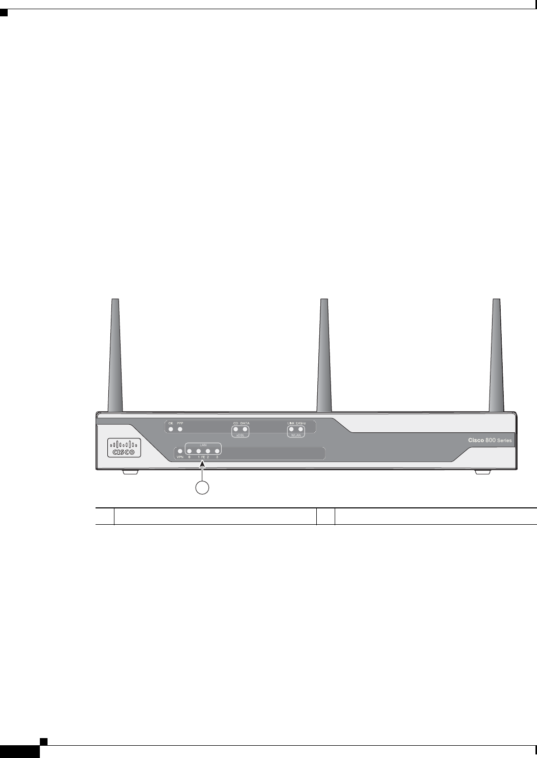
Figure 1-1 shows the front panel details of the Cisco 860 wireless router.
Figure 1-1 Front Panel of the Cisco 860 Series Wireless ISR
1LEDs
231969
1
1-3
Cisco 860 Series, Cisco 880 Series, and Cisco 890 Series Integrated Services Routers Hardware Installation Guide
OL-16193-07
Chapter 1 Product Overview
Cisco 860VAE Series ISRs
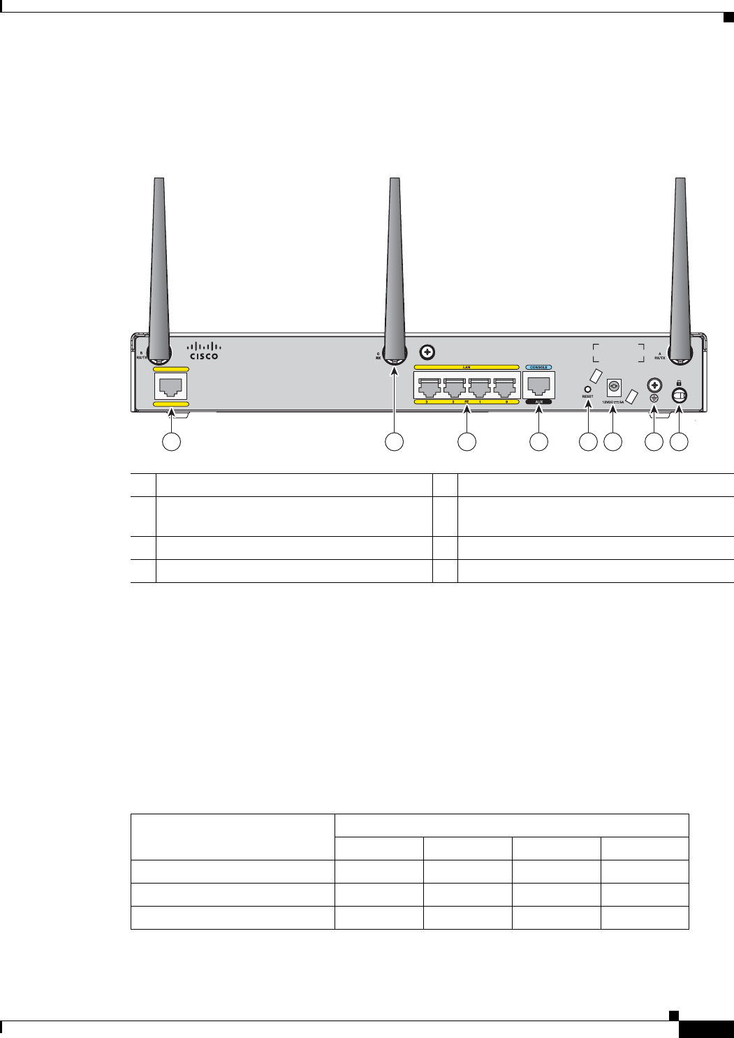
Figure 1-2 shows the back panel details of the Cisco 861 wireless (861W) ISR. Nonwireless routers do
not have antennas on the back panel. However, the feature locations are similar for all Cisco 860 series
routers.
Figure 1-2 Back Panel of the Cisco 861W ISR
Cisco 860VAE Series ISRs
The Cisco 860VAE series ISRs are fixed-configuration data routers. This section describes the features
of the products in this series.
Interfaces
Table 1-1 describes the interfaces of the Cisco 860VAE series routers.
1Primary WAN port—10/100 5Reset button
2Antenna—captive omnidirectional dipole
WLAN antenna (wireless models only)
6Power connector
34-port 10/100 Ethernet switch 7Earth ground connection
4Serial port—console or auxiliary 8Kensington security slot
232181
31 4 6 7 852
WAN
FE 4
Cisco 861W
Tabl e 1-1 Interfaces of the Cisco 860VAE Series ISRs
Interfaces
Model
866VAE 867VAE 866VAE-K9 867VAE-K9
4 FE
1
switch ports xxxx
1 GE
2
switch port — — x x
1 GE WAN port xxxx
1-4
Cisco 860 Series, Cisco 880 Series, and Cisco 890 Series Integrated Services Routers Hardware Installation Guide
OL-16193-07
Chapter 1 Product Overview
Note
The Cisco 866VAE, 867VAE, 866VAE-K9, and 867VAE-K9 routers each have two WAN ports. Only
one of the two ports can be active at any given time.
IOS Images
Table 1-2 describes the IOS images included in Cisco 860VAE series routers.
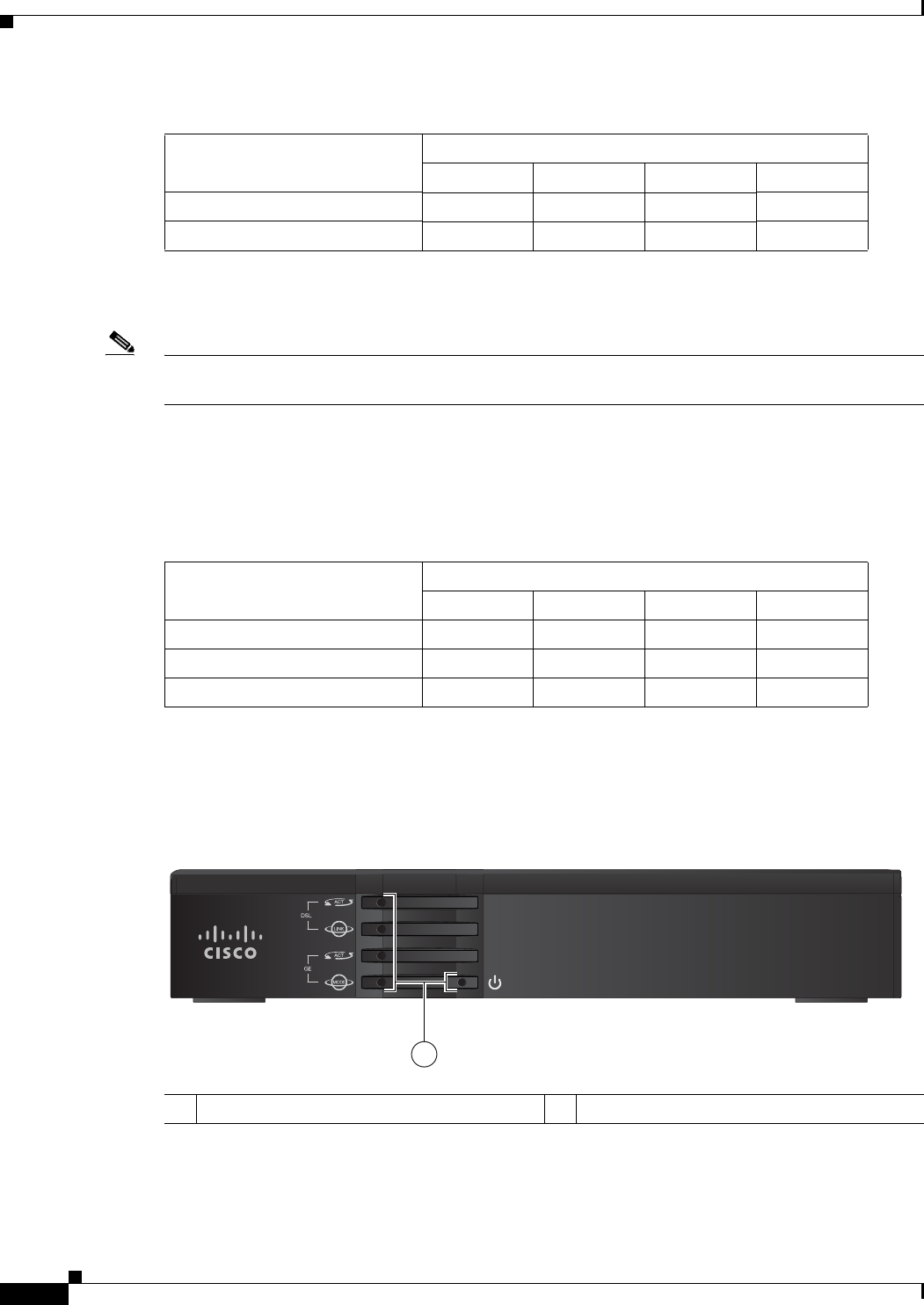
Figure 1-3 shows the front panel details of the Cisco 866VAE, Cisco 867VAE, Cisco 866VAE-K9, and
Cisco 867VAE-K9 integrated services routers (ISRs).
Figure 1-3 Front Panel of the Cisco 860VAE series ISR
1 VDSL/ADSL over POTS port — x — x
1 VDSL/ADSL over ISDN port x — x —
1. FE = Fast Ethernet
2. GE = Gigabit Ethernet
Table 1-1 Interfaces of the Cisco 860VAE Series ISRs
Interfaces
Model
866VAE 867VAE 866VAE-K9 867VAE-K9
Tabl e 1-2 IOS Images of the Cisco 860VAE Series ISRs
IOS Image
Model
866VAE 867VAE 866VAE-K9 867VAE-K9
c860vae-ipbasek9-mz x x — —
c860vae-advsecurityk9-mz — — x x
c860vae-advsecurityk9_npe-mz — — x x
1LEDs
246199
Cisco 860 Series
1
1-5
Cisco 860 Series, Cisco 880 Series, and Cisco 890 Series Integrated Services Routers Hardware Installation Guide
OL-16193-07
Chapter 1 Product Overview
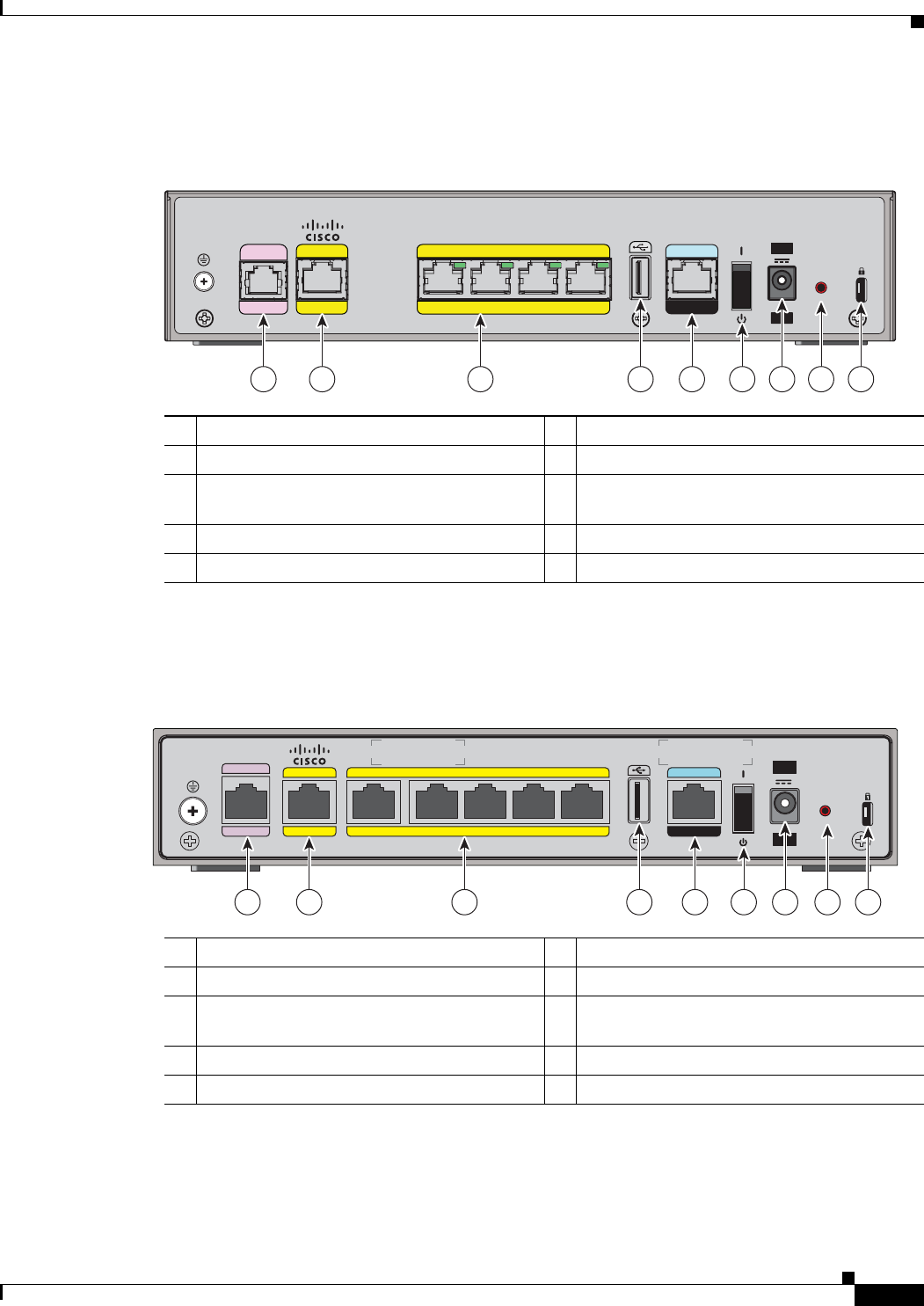
Figure 1-4 shows the back panel details of the Cisco 866VAE ISR.
Figure 1-4 Back Panel of the Cisco 866VAE ISR
Figure 1-5 shows the back panel details of the Cisco 867VAE-K9.
Figure 1-5 Back Panel of the Cisco 867VAE-K9 ISR
Cisco 880 Series ISRs
The Cisco 880 series ISRs have data and voice capabilities. They have the following features:
1xDSL port 6On/Off switch
2GE WAN interface 7Power connector
3Ethernet LAN FE interfaces (FE0 through
FE3 interfaces)
8Reset button
4USB port 9Kensington security slot
5Serial port—console or auxiliary
246200
CONSOLE
AUX
FE 2 FE 1 FE 0FE 3OVER ISDN
LAN
WAN
GE0
VDSL/ADSL
12V 2.5A
RESET
Cisco 866VAE
1 2 3 4 7 8 95 6
1xDSL port 6On/Off switch
2GE WAN interface 7Power connector
3Ethernet LAN GE and FE interfaces (GE0
interface and FE0 through FE3 interfaces)
8Reset button
4USB port 9Kensington security slot
5Serial port—console or auxiliary
284558
CONSOLE
AUX
OVER POTS
WAN LAN
GE1 GE0 FE3 FE2 FE1 FE0
VDSL/ADSL
12V 2.5A
RESET
Cisco 867VAE-K9
1 2 3 4 7 8 95 6

1-6
Cisco 860 Series, Cisco 880 Series, and Cisco 890 Series Integrated Services Routers Hardware Installation Guide
OL-16193-07
Chapter 1 Product Overview
Cisco 880 Series ISRs
•
Integrated 4-port 10/100 Ethernet switch for connecting to the LAN
•
10/100 FE, VDSLoPOTS, ADSL over POTS, ADSL over ISDN, DSL Multi-mode
(VDSL/ADSLoPOTS, VDSL/ADSLoISDN Cisco VA models only), or G.SHDSL port for
connecting to the WAN
•
Optional embedded Wi-Fi CERTIFIED™, 802.11b/g/n-compliant wireless AP
•
Optional 2-port Power over Ethernet (PoE)
Note
The Cisco 880 series ISRs can include an optional PoE module that provides power to
802.3af-compliant devices connected to ethernet ports 0 and 1. If this feature was not
configured with the factory order, you must order and install it to enable the PoE function.
•
DIMM expansion socket that can accept up to 512 MB of additional memory, for a total of 768 MB
system memory
The following features are located on the front panel:
•
Universal serial bus (USB) 1.1 port
•
Express card slot for third-generation (3G) cellular data WAN connectivity, available only on the
Cisco 88xG models
This section contains the following topics:
•
Cisco 880 Series Data Routers, page 1-6
•
Cisco 880 Series Voice and Data Routers, page 1-9
Cisco 880 Series Data Routers
The Cisco 880 series data routers provide integrated VPN, embedded Wi-Fi CERTIFIED™,
802.11b/g/n-compliant wireless AP, 3G, and backup capabilities. Figure 1-6 through Figure 1-9 show the
features available on Cisco 880 series data routers. Some of the features shown may not be available on
your router.
1-7
Cisco 860 Series, Cisco 880 Series, and Cisco 890 Series Integrated Services Routers Hardware Installation Guide
OL-16193-07
Chapter 1 Product Overview
Cisco 880 Series ISRs
Depending on the router model, the primary WAN port can be G.SHDSL, VDSLoPOTS, VDSL/ADSL
over ISDN, VDSL/ADSL over POTS, or 10/100 FE. See the Cisco 880 Series Integrated Services
Routers data sheet for the WAN interface that is supported on your router.
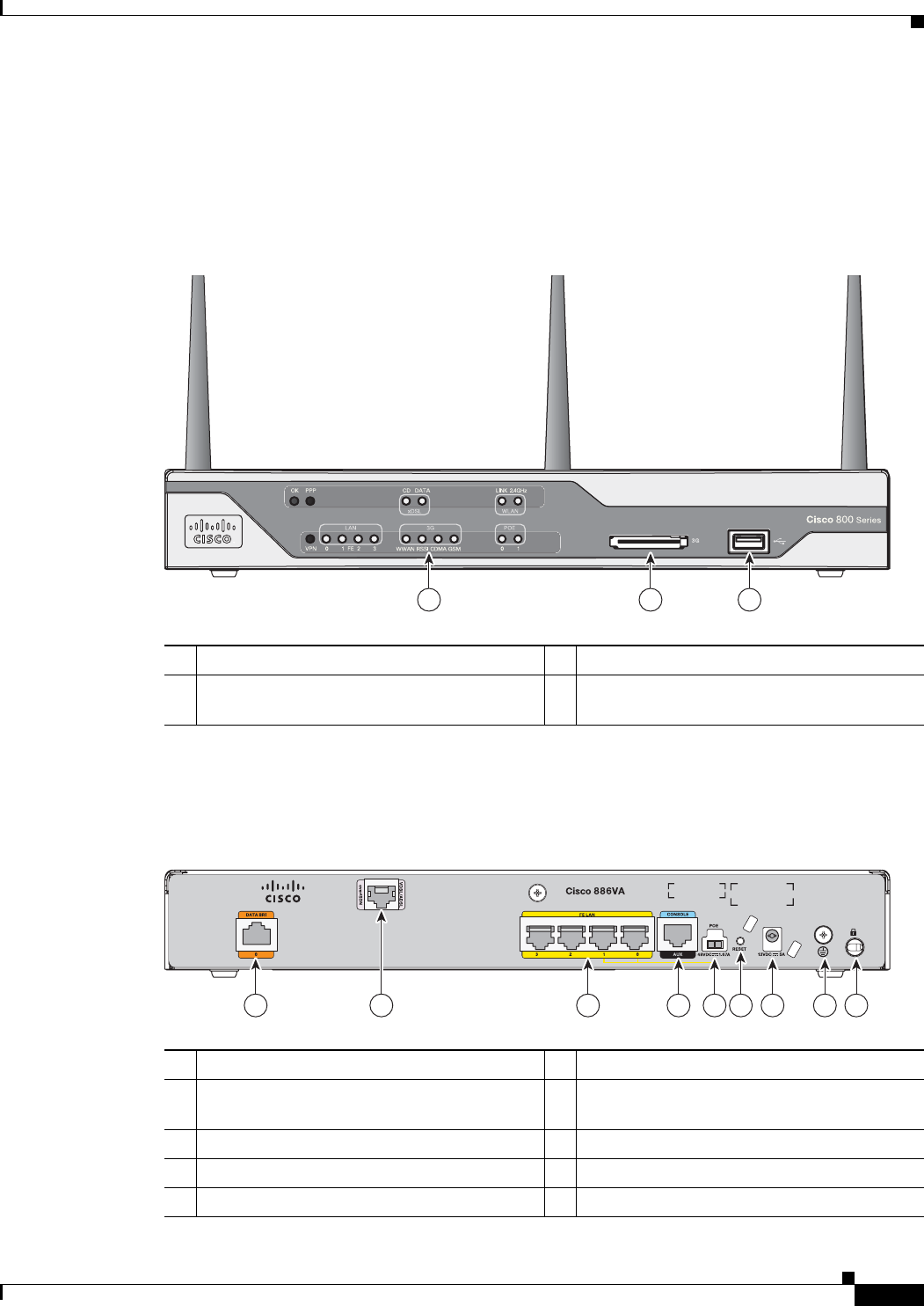
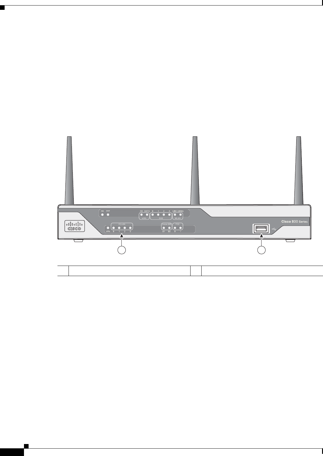
Figure 1-6 shows the front panel details of the Cisco 880 wireless data router. The USB port and the 3G
card slot are located on the front panel.
Figure 1-6 Front Panel of the Cisco 880 Series Wireless Data Router
Figure 1-7 shows the back panel details of the Cisco 886VA data router.
Figure 1-7 Back Panel of the Cisco 886VA Router
1LEDs 3USB port
23G express card slot—Supports third-party
1
3G card (Cisco 88xG models only)
1. See the Cisco 880 Series Integrated Services Routers data sheet for supported vendors.
231950
1 2 3
254090
1 3 4 5 7 8 962
1Data BRI
1
0 6Reset button
2Primary WAN port—VDSL/ADSL over
ISDN
7Power connector
34-port 10/100 Ethernet switch
2
8Earth ground connection
4Serial port—console or auxiliary 9Kensington security slot
5PoE power connector—optional
1-8
Cisco 860 Series, Cisco 880 Series, and Cisco 890 Series Integrated Services Routers Hardware Installation Guide
OL-16193-07
Chapter 1 Product Overview
Cisco 880 Series ISRs
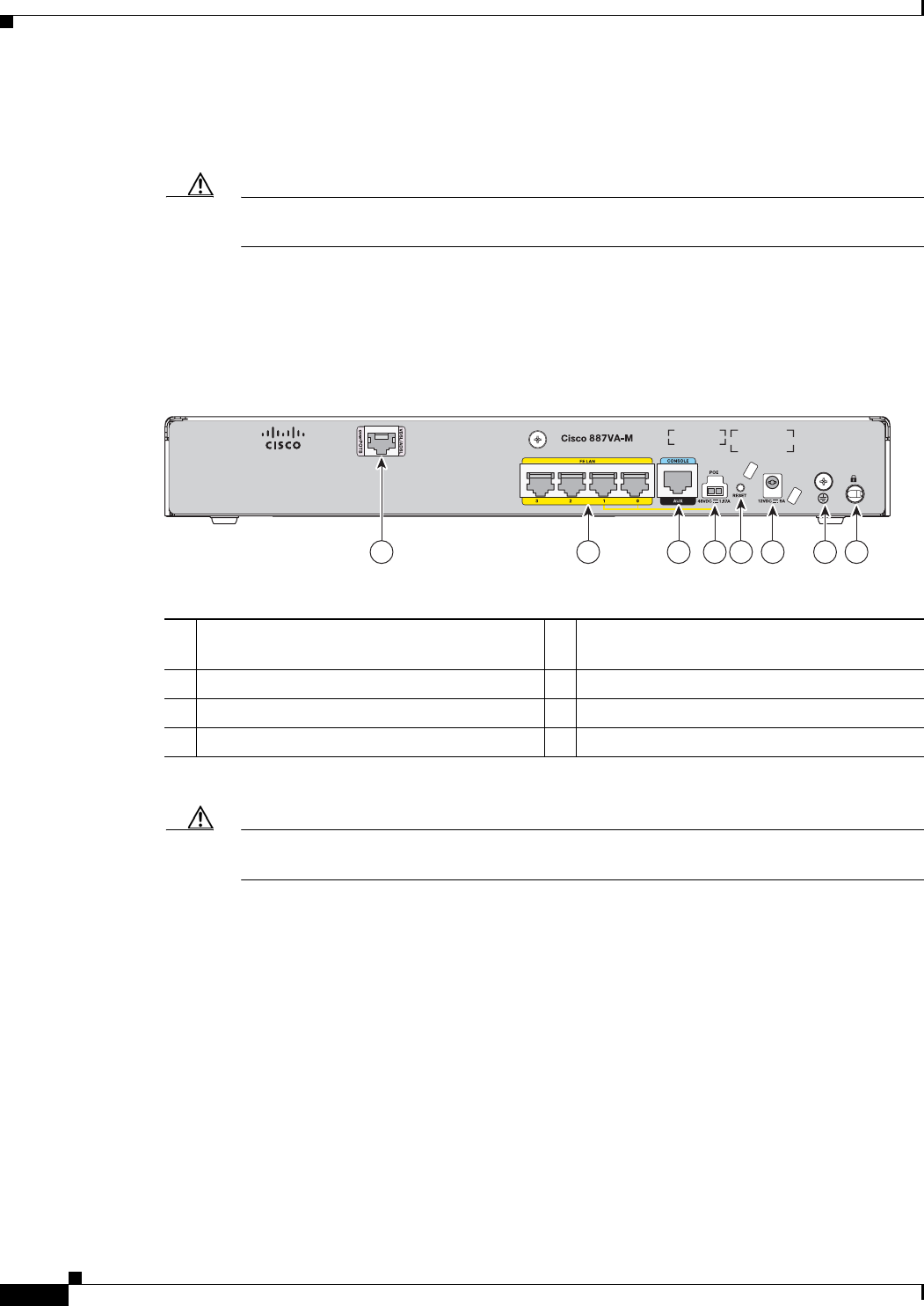
Figure 1-8 shows the back panel details of the Cisco 887VA and 886VA-M data router.
Figure 1-8 Back Panel of the Cisco 887VA and 887VA-M Router
1. BRI = Basic rate interface.
2. Ports 0 and 1 provide PoE with the optional PoE module installed.
Caution
The primary WAN port is designed for an RJ-45 connector only. Damage to the primary WAN
port may occur if a non RJ-45 connector is inserted.
254139
2 3 4 6 7 851
1Primary WAN port—VDSL/ADSL over
POTS
1
5Reset button
24-port 10/100 Ethernet switch
2
6Power connector
3Serial port—console or auxiliary 7Earth ground connection
4PoE power connector—optional 8Kensington security slot
1. 887VA-M has Annex M support.
2. Ports 0 and 1 provide PoE with the optional PoE module installed.
Caution
The primary WAN port is designed for an RJ-45 connector only. Damage to the primary WAN
port may occur if a non RJ-45 connector is inserted.
1-9
Cisco 860 Series, Cisco 880 Series, and Cisco 890 Series Integrated Services Routers Hardware Installation Guide
OL-16193-07
Chapter 1 Product Overview
Cisco 880 Series ISRs
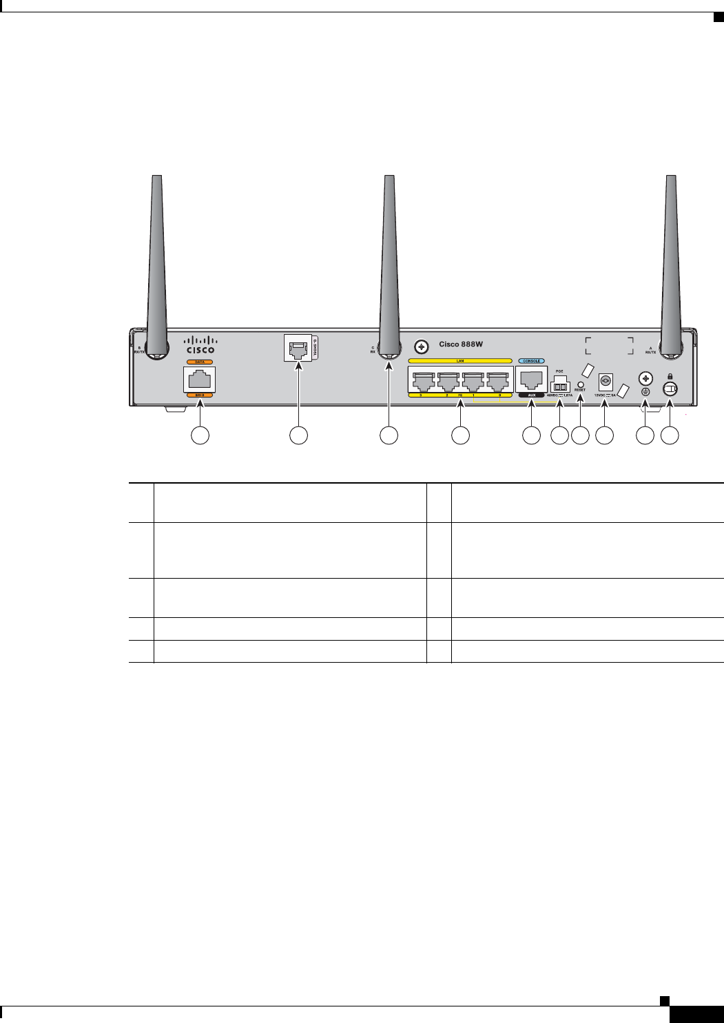
Figure 1-9 shows the back panel details of the Cisco 888W data router. Nonwireless routers do not have
antennas on the back panel. However, the feature locations are similar across all Cisco 880 series data
routers.
Figure 1-9 Back Panel of the Cisco 888W Data Router
Cisco 880 Series Voice and Data Routers
The Cisco 880 series voice and data routers provide both voice and data ports. The voice ports managed
voice services that interface with Foreign Exchange Station (FXS), Foreign Exchange Office (FXO), or
BRI connections.
231951
1 4 5 6 8 9 1072 3
1ISDN port—not available on 3G models 6PoE power connector for optional PoE
module
1
2Primary WAN port
2
—G.SHDSL,
VDSLoPOTS, ADSLoPOTS, ADSLoISDN,
or 10/100 FE
7Reset button
3Antenna—captive omnidirectional dipole
WLAN antenna (wireless models only)
8Power connector
44-port 10/100 Ethernet switch 9Earth ground connection
5Serial port—console or auxiliary 10 Kensington security slot
1. The Cisco 880 series ISRs can include an optional PoE module that provides power to 802.3af-compliant devices connected
to ethernet ports 0 and 1. If this feature was not configured with the factory order, you must order and install it to enable the
PoE function.
2. Depending on the router model, the primary WAN port can be G.SHDSL, VDSLoPOTS, or 10/100 FE. The VDSLoPOTS
port is in the same location as the G.SHDSL port. The 10/100 FE WAN port is located at the bottom left corner. See Figure 1-2
for the location of the 10/100 FE WAN port.
1-10
Cisco 860 Series, Cisco 880 Series, and Cisco 890 Series Integrated Services Routers Hardware Installation Guide
OL-16193-07
Chapter 1 Product Overview
Cisco 880 Series ISRs
Cisco 881 SRST and Cisco 888 SRST
Figure 1-10, Figure 1-11, and Figure 1-12 show the features available on the Cisco 881 SRST and
Cisco 888 SRST routers. The features available vary, depending on the router model. Some features may
not be available on your router.
Depending on the router model, the primary WAN port can be either G.SHDSL or 10/100 FE. See the
Cisco 880 Series Integrated Services Routers data sheet for the WAN interface and voice ports that are
supported on your router.
Figure 1-10 shows the front panel details of the Cisco 881 SRST and Cisco 888 SRST wireless voice
router.
Figure 1-10 Front Panel of the Cisco 881 SRST and Cisco 888 SRST Wireless Voice Router
1LEDs 2USB port
270495
1 2
1-11
Cisco 860 Series, Cisco 880 Series, and Cisco 890 Series Integrated Services Routers Hardware Installation Guide
OL-16193-07
Chapter 1 Product Overview
Cisco 880 Series ISRs
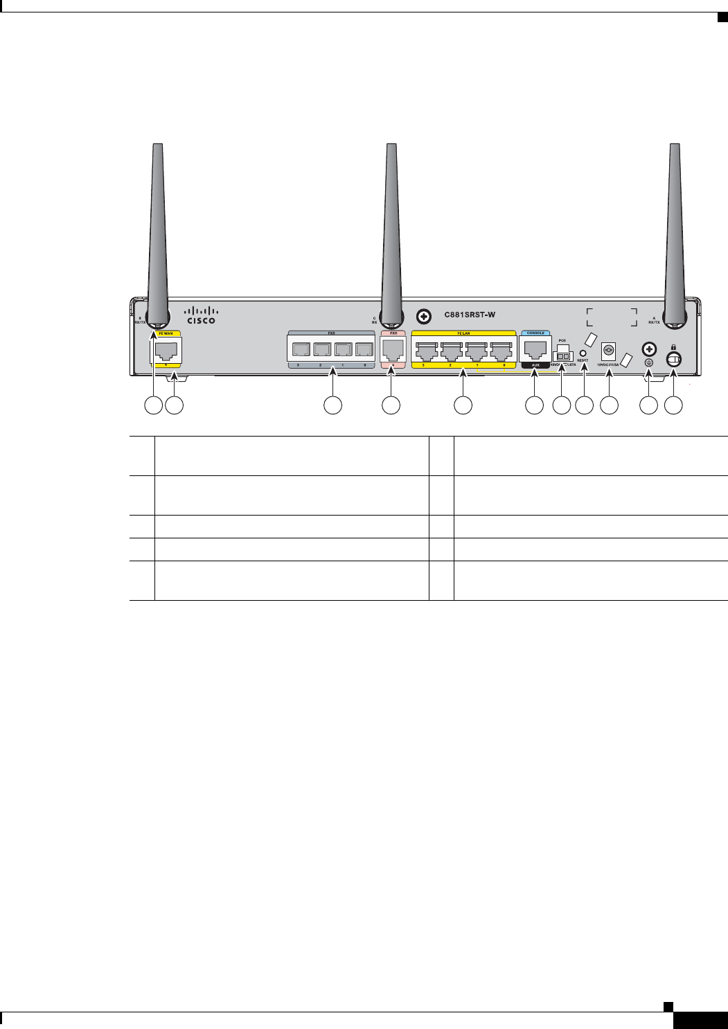
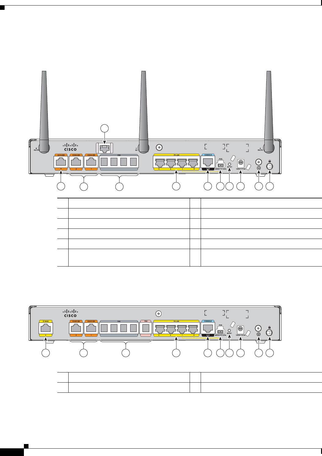
Figure 1-11 shows the back panel details of the Cisco 881SRST-W voice router.
Figure 1-11 Back Panel of the Cisco C881SRST-W Voice Router
1Primary WAN port
1
—10/100 FE
1. Depending on the router model, the primary WAN port can be either G.SHDL or 10/100 FE.
6Antenna—captive wireless omnidirectional
dipole WLAN antenna (wireless models only)
2Voice ports—four FXS
2
/DID
3
ports, one
FXO
4
port with TBP
5
power failover
2. FXS = Foreign Exchange Station.
3. DID = Direct Inward Dialing.
4. FXO = Foreign Exchange Office.
5. TBP = trunk bypass.
7Reset button
34-port 10/100 Ethernet switch
6
6. Ports 0 and 1 provide PoE with the optional PoE module installed.
8Power connector
4Serial port—console or auxiliary 9Earth ground connection
5PoE power connector for optional PoE
module
7
7. The Cisco 880 series ISRs can include an optional PoE module that provides power to 802.3af-compliant devices connected
to ethernet ports 0 and 1. If this feature was not configured with the factory order, SKU 800-IL-PM-2, you must order and
install it to enable the PoE function. The PoE power supply, SKU 800-ILPM-4, is also required.
10 Kensington security slot
241904
31 4 7 98 1022 56
1-12
Cisco 860 Series, Cisco 880 Series, and Cisco 890 Series Integrated Services Routers Hardware Installation Guide
OL-16193-07
Chapter 1 Product Overview
Cisco 880 Series ISRs
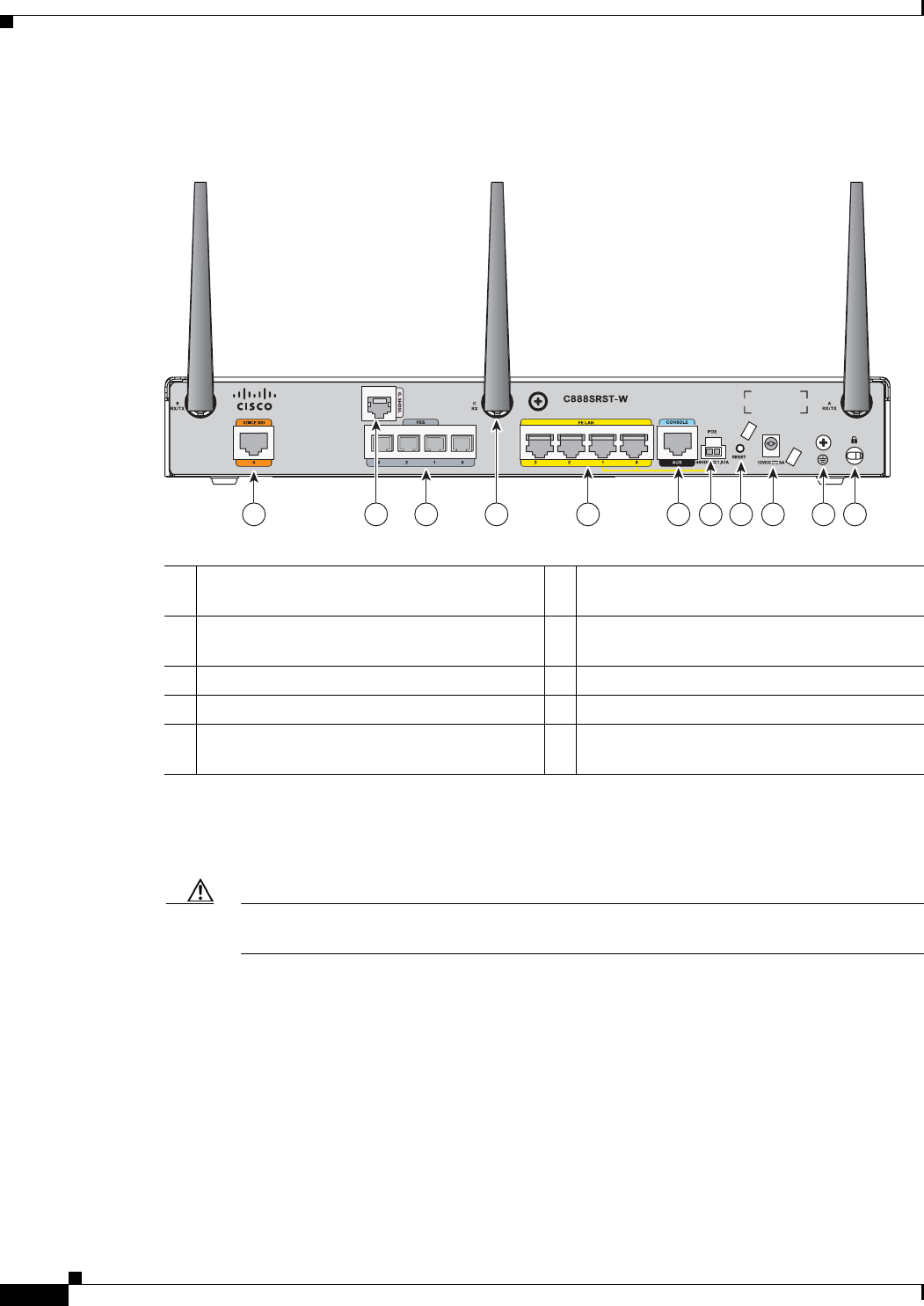
Figure 1-12 shows the back panel details of the Cisco 888SRST-W voice router.
Figure 1-12 Back Panel of the Cisco C888SRST-W Voice
Cisco 881-V, Cisco 887VA-V, and Cisco 887VA-V-W
Figure 1-13, Figure 1-14, and Figure 1-15 show the features available on the Cisco 881-V and
Cisco 887VA-V routers. The features available vary, depending on the router model. Some features may
not be available on your router.
The Cisco 881-V and Cisco 887VA-V voice and data series gives you the flexibility to use either FXS
or BRI voice ports. However, the number of concurrent calls that can be supported by the router is
limited by the codec complexity setting on the router. Table 1-3 lists the maximum number of calls that
is supported when the codec complexity command is configured for Flexible, Medium or High
complexity.
1Primary WAN port
1
—G.SHDSL
1. Depending on the router model, the primary WAN port can be either G.SHDL or 10/100 FE.
6Antenna—captive wireless omnidirectional
dipole WLAN antenna (wireless models only)
2Voice ports—four FXS/DIDports and one
voice BRI port
7Reset button
34-port 10/100 Ethernet switch
2
2. Ports 0 and 1 provide PoE with the optional PoE module installed.
8Power connector
4Serial port—console or auxiliary 9Earth ground connection
5PoE power connector for optional PoE
module
3
3. The Cisco 880 series ISRs can include an optional PoE module that provides power to 802.3af-compliant devices connected
to ethernet ports 0 and 1. If this feature was not configured with the factory order, SKU 800-IL-PM-2, you must order and
install it to enable the PoE function. The PoE power supply, SKU 800-ILPM-4, is also required.
Caution
The primary WAN port on all 888E models is designed for an RJ-45 connector only. Damage
to the primary WAN port may occur if a non RJ-45 connector is inserted.
10 Kensington security slot
241905
32 2 4 7 9 1086 51
1-13
Cisco 860 Series, Cisco 880 Series, and Cisco 890 Series Integrated Services Routers Hardware Installation Guide
OL-16193-07
Chapter 1 Product Overview
Cisco 880 Series ISRs
Note
Configuring the codec complexity setting to support secure calls uses DSP resources, but does not affect
the maximum number of supported calls.
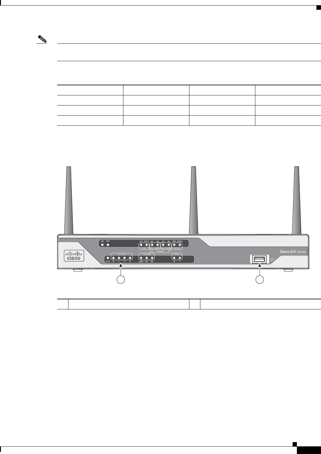
Figure 1-13 shows the front panel details of the Cisco 881-V, Cisco 887VA-V, and Cisco 887VA-V-W.
Figure 1-13 Front Panel of the Cisco 881-V, Cisco 887VA-V, and Cisco 887VA-V-W Routers
Tabl e 1-3 Maximum Number of Supported Calls
Flexible Complexity Medium Complexity High Complexity
C881-V 986
C887VA-V 886
C887VA-V-W 886
246861
1 2
1LEDs 2USB port
1-14
Cisco 860 Series, Cisco 880 Series, and Cisco 890 Series Integrated Services Routers Hardware Installation Guide
OL-16193-07
Chapter 1 Product Overview
Cisco 880 Series ISRs
Figure 1-14 shows the back panel for the Cisco 887VA-V-W router. The Cisco 887VA-V (nowireless)
router does not have the antennas on the back panel.
Figure 1-14 Back Panel of the Cisco 887 VA-V Router
Figure 1-15 shows the back panel for the Cisco 881-V router.
Figure 1-15 Back Panel of the Cisco 881V Router
1Data BRI 6PoE power connector (optional)
2Voice BRI 7Reset Button
3Voice ports—four FXS/DID ports 8Power connector
4Fast Ethernet LAN—four ports 9 Earth ground connection
5Console Port 10 Kensington security slot
11 Primary WAN port—VDSL/ADSL over
POTS
246864
overPO T S
VDSL/ADSL
C887VA-W VO ICE
3
4
56
1 4 5 6 8 9 107
32
11
246866
C881 VO ICE
3
4
56 7
1 4 5 6 8 9 10732
1Fast Ethernet WAN port 6PoE power connector (optional)
2Voice BRI ports 7Reset button

1-15
Cisco 860 Series, Cisco 880 Series, and Cisco 890 Series Integrated Services Routers Hardware Installation Guide
OL-16193-07
Chapter 1 Product Overview
Cisco 890 Series ISRs
Cisco 890 Series ISRs
The Cisco 890 series ISRs have the following features:
•
Integrated 8-port 10/100 Ethernet switch for connecting to the LAN
•
10/100 FE and 10/100/1000 Gigabit Ethernet (GE) port for connecting to the WAN
•
Separate console and auxiliary ports
•
Optional embedded Wi-Fi CERTIFIED™ dual radio 802.11a/b/g/n-compliant wireless AP
•
Optional 4-port PoE
Note
The Cisco 890 series ISRs can include an optional PoE module that provides power to
802.3af-compliant devices connected to ethernet ports 0 through 3. If this feature was not
configured with the factory order you must order and install it to enable the PoE function.
•
Security feature card (SFC) socket
•
DIMM expansion socket that can accept up to 512 MB of additional memory, for a total of 768 MB
system memory in Cisco 891 and 892 series ISRs, and a total of 1 GB system memory in
Cisco 892F series ISRs
•
Three reverse-polarity threaded Neill-Concelman (RP-TNC) connectors on the back panel for
non-captive dual-band WLAN antenna (wireless models only)
•
Supports the AIM2-CUE-K9 and AIM2-APPRE-104-K9
•
Gigabit Ethernet (GE) small-form-factor pluggable (SFP) port (Cisco 892F series ISRs only)
The following feature is located on the front panel:
•
Two USB 1.1 ports
3Voice ports—four FXS/DID ports and one
FXO port.
8Power connector
4Fast Ethernet LAN—four ports 9Earth ground connection
5Console Port 10 Kensington security slot
1-16
Cisco 860 Series, Cisco 880 Series, and Cisco 890 Series Integrated Services Routers Hardware Installation Guide
OL-16193-07
Chapter 1 Product Overview
Cisco 890 Series ISRs
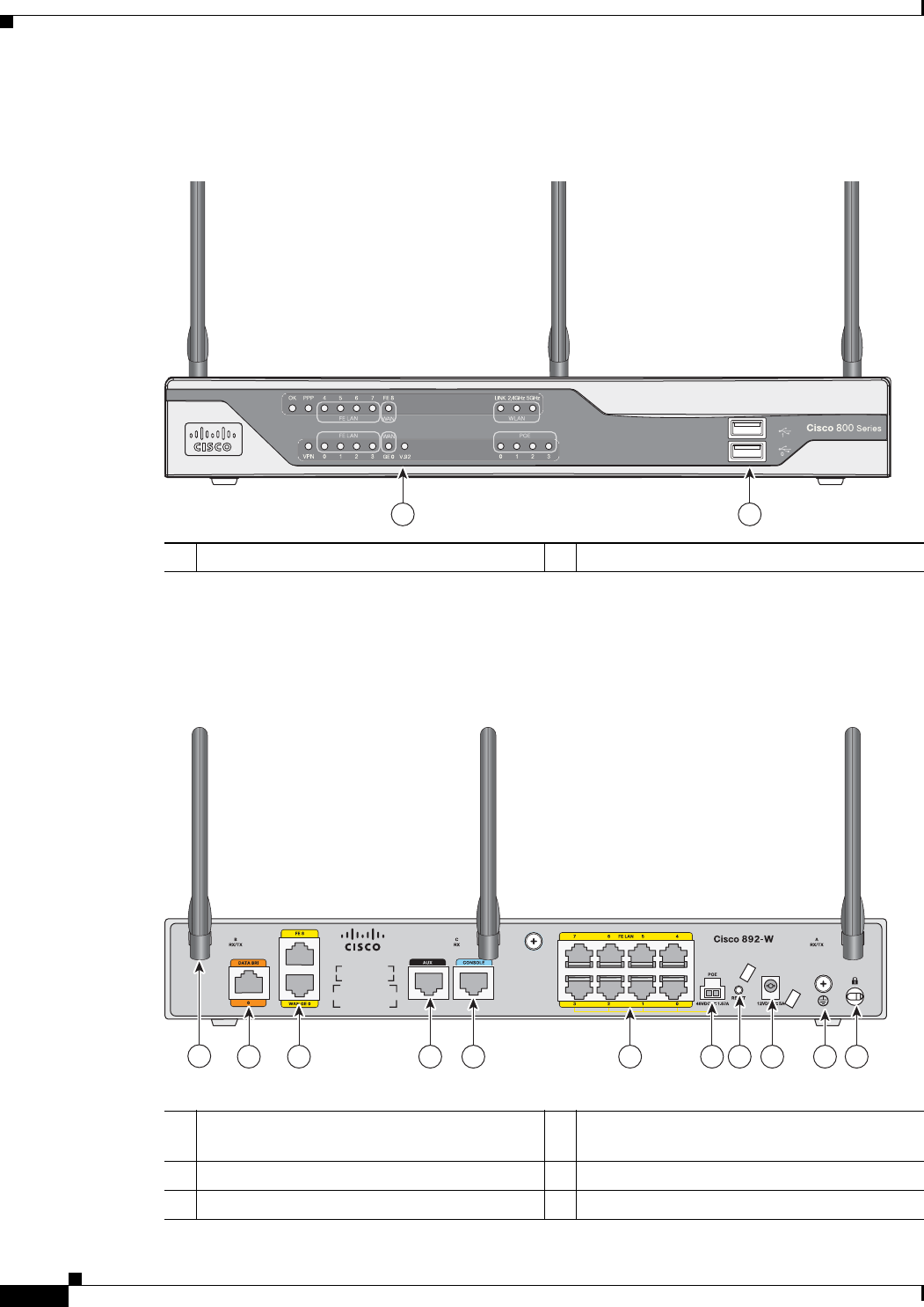
Figure 1-16 shows the front panel details of the Cisco 890 wireless router.
Figure 1-16 Front Panel of the Cisco 890 Series Wireless ISR
Figure 1-17 shows the back panel details of the Cisco 892-W router. Nonwireless routers do not have
RP-TNC antennas or connectors on the back panel. Some of the features that are shown may not be
available on your router. However, the feature locations are similar across all Cisco 890 series routers.
Figure 1-17 Back Panel of the Cisco 892-W Router
1LEDs 2USB ports
272367
1 2
1Antenna—dipole swivel antenna attached to
RP-TNC connectors (wireless models only)
7PoE power connector for optional PoE
module
1
2Backup—Data BRI
2
or V.92
3
port 8Reset button
3Primary WAN port—FE and GE 9Power connector
272369
14 5 6 8 9 10 1172 3
1-17
Cisco 860 Series, Cisco 880 Series, and Cisco 890 Series Integrated Services Routers Hardware Installation Guide
OL-16193-07
Chapter 1 Product Overview
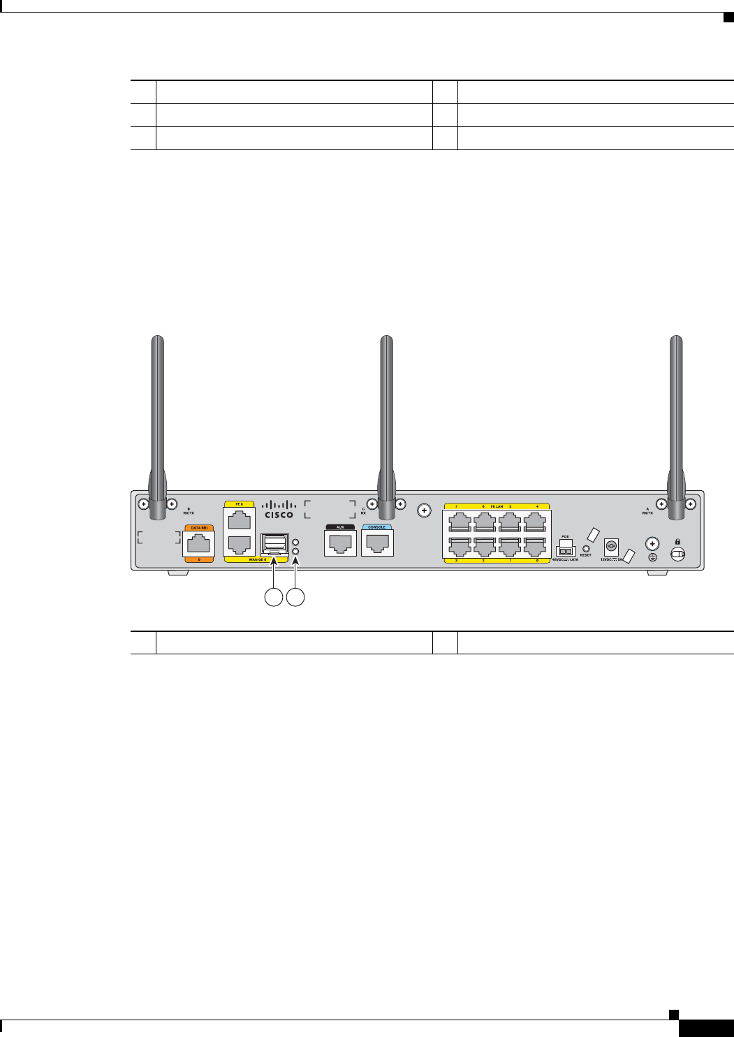
Hardware Features
Figure 1-18 shows the location of the SFP port in a Cisco 892F-W router.
Figure 1-18 SFP Port Location in a Cisco 892F-W Router
Hardware Features
This section provides an overview of the following hardware features for the Cisco 860 series, 880
series, and 890 series ISRs. A feature summary is available at the end of this section.
•
Kensington Lock
•
Reset Button
•
LEDs
•
Memory
•
USB Port
•
Fan
•
Power over Ethernet Module
•
3G Cellular Data WAN Connectivity
4Auxiliary port 10 Earth ground connection
5Console port 11 Kensington security slot
68-port 10/100 Ethernet switch
1. The Cisco 890 series ISRs can include an optional PoE module that provides power to 802.3af-compliant devices connected
to ethernet ports 0 through 3. If this feature was not configured with the factory order you must order and install it to enable
the PoE function.
2. The Data BRI port is available only on the Cisco 892 router models.
3. The V.92 port (not shown) is available only on the Cisco 891 router models and is located between the console port and the
Ethernet switch.
1SFP port 2SFP LEDs
278179
Cisco 892F-W
SFP
EN
S
21

1-18
Cisco 860 Series, Cisco 880 Series, and Cisco 890 Series Integrated Services Routers Hardware Installation Guide
OL-16193-07
Chapter 1 Product Overview
Hardware Features
•
Wireless LAN Connectivity
•
Small Form-Factor Pluggable Port
•
Feature Summary
Kensington Lock
A Kensington security slot is located on the router back panel. To secure the router to a desktop or other
surface, use the Kensington lockdown equipment.
Reset Button
The Reset button is used to restore the router to the factory default configuration. To do this, press the
reset button within five seconds of powering up the router.
Note
If you execute a CLI reboot command while the embedded wireless AP is running Cisco Unified IOS
software, the router reboots, but the AP continues running. Clients with Cisco Unified IOS software are
controlled by a wireless LAN controller (WLC) and can be reset only by the controller.
Cisco 860VAE Routers—Custom Configuration File
On Cisco 860VAE routers, the reset button can be used to load a custom configuration file without
having to use the CLI. The configuration file can be located on an external USB flash drive or on the
router's compact flash.
The custom configuration file must be named one of the following:
•
customer-config
•
SN-customer-config
where “SN” is the unique hardware serial number.
When the system attempts to load a custom configuration file, configuration files on a USB flash drive
have priority over configuration files on the router's flash drive and the “SN-customer-config” file name
has priority over the “customer-config” file name. The priority for loading a configuration file is as
follows:
1.
USB flash0: SN-customer-config
2.
USB flash0: customer-config
3.
Router flash: SN-customer-config
4.
Router flash: customer-config
If the router does not find a valid custom configuration file, the system aborts the process.
To reset the router to the factory default configuration, follow these steps:
Step 1
Verify that IOS is running correctly by checking that the system status LED is on.
1-19
Cisco 860 Series, Cisco 880 Series, and Cisco 890 Series Integrated Services Routers Hardware Installation Guide
OL-16193-07
Chapter 1 Product Overview
Hardware Features
Step 2
Press and hold the reset button until the system status LED begins to flash. Typically, this occurs within
five seconds.
The router reloads itself after the startup configuration has been replaced with the new customer
configuration.
LEDs
The LEDs are located on the front panel of the router.
•
Table 1-4 describes the LEDs for the Cisco 860 series, 880 series, and 890 series ISRs.
•
Table 1-5 lists the LED descriptions for the Cisco 866VAE, Cisco 867VAE, Cisco 866VAE-K9, and
Cisco 867VAE-K9 ISRs.
Tabl e 1-4 LED Descriptions for the Cisco 860 Series, Cisco 880 Series, and Cisco 890 Series ISRs
LED Color Description 860 Series 880 Series 890 Series
Power OK Green On—DC power is being supplied to the router and the
Cisco IOS software is running.
Blinking—Bootup is in process, or the router is in
ROMMON monitor mode.
Off—Power is not supplied to the router.
All models All models All models
Link Status FE0 Green On—Ethernet port is connected.
Blinking—Data is either being received or being
transmitted.
Off—Ethernet port is not connected.
All models All models All models
Link Status FE1
Link Status FE2
Link Status FE3
Link Status FE4 Green On—Ethernet port is connected.
Blinking—Data is either being received or being
transmitted.
Off—Ethernet port is not connected.
— — All models
Link Status FE5
Link Status FE6
Link Status FE7
FE WAN Port
Link Status
Green On—Port is connected.
Blinking—Data is either being received or being
transmitted.
Off—Port is not connected.
861
models
881
models
All models
GE WAN Port
Link Status
Green On—Port is connected.
Blinking—Data is either being received or being
transmitted.
Off—Port is not connected.
— — All models

1-20
Cisco 860 Series, Cisco 880 Series, and Cisco 890 Series Integrated Services Routers Hardware Installation Guide
OL-16193-07
Chapter 1 Product Overview
Hardware Features
WLAN
(2.4 GHz)
Green On—Radio is connected, SSID
1
is configured, and client
is associated, but no data is being received or being
transmitted.
Slow blinking—Radio is connected, SSID is configured,
and beacons are being transmitted.
Fast blinking—Data is either being received or being
transmitted.
Off—Radio is shut down, and no SSID is configured.
Wireless
models
Wireless
models
Wireless
models
WLAN (5 GHz) Green On—Radio is connected, SSID is configured, and client
is associated, but no data is being received or being
transmitted.
Slow blinking—Radio is connected, SSID is configured,
and beacons are being transmitted.
Fast blinking—Data is either being received or being
transmitted.
Off—Radio is shut down, and no SSID is configured.
— — Wireless
models
WLAN LINK
(Autonomous
Mode)
Green On—Wireless link is up.
Blinking—Ethernet link is up, and data is either being
received or being transmitted.
Off—Wireless link is down.
Wireless
models
Wireless
models
Wireless
models
WLAN LINK
(Unified Mode)
Green On—Ethernet link is up, and wireless access point (AP) is
communicating with LWAPP
2
controller.
Blinking—Ethernet link is up, but wireless AP is not
communicating with LWAPP controller.
Off—Ethernet link is down.
—Wireless
models
Wireless
models
PoE Green On—PoE is connected and powered.
Off—PoE is not installed.
—Models
with PoE
Models
with PoE
Amber On—Fault with the PoE.
VPN Green On—VPN is connected. —All models All models
PPP
3
Green On—At least one PPP session is established. —All models All models
xDSL
4
CD Green On—The xDSL interface is connected to the DSLAM
5
.
Blink—Training to the line.
Off—Indicates that a connection has not been established
or the port is shut down.
—887,
887VA,
887VA-M8
888
models
—
xDSL Data Green Blink—The xDSL interface is either receiving or
transmitting data.
Off—No data is being transmitted or being received.
—887,
887VA,
887VA-M8
88 models
—
Data BRI LINK Green On—ISDN D channel is connected. —887, 888
models
892
models
Table 1-4 LED Descriptions for the Cisco 860 Series, Cisco 880 Series, and Cisco 890 Series ISRs (continued)
LED Color Description 860 Series 880 Series 890 Series

1-21
Cisco 860 Series, Cisco 880 Series, and Cisco 890 Series Integrated Services Routers Hardware Installation Guide
OL-16193-07
Chapter 1 Product Overview
Hardware Features
Data BRI B1 Green Blinking—B1 channel is either receiving or sending data,
or data is passing through ISDN channel 1.
—887, 888
models
892
models
Data BRI B2 Green Blinking—B2 channel is receiving or sending data, or
data is passing through ISDN channel 2.
—887, 887V,
888
models
892
models
3G
6
WWAN
7
Green On—Service is established.
Slow Blinking—Searching for service.
Fast Blinking—Data is either being received or being
transmitted.
—3G models —
3G RSSI
8
Green Off—Low signal strength (lower than -100 dBm).
On—High RSSI (-69 dBm or higher).
Slow Blinking—Low or medium RSSI (-99 to -90 dBm).
Fast Blinking—Medium RSSI (-89 to -70 dBm).
—3G models —
Amber On—No service. —3G models —
3G GSM
9
Green On—Service is established.
Off—No service.
—3G models —
3G CDMA
10
Green On—Service is established.
Off—No service.
—3G models —
FXO Voice Green On—FXO port is connected.
Blinking—FXO port is either receiving or transmitting
data.
—881
11
—
BRI Voice LNK Green On—BRI interface is connected. — — —
BRI Voice B1 Green On—BRI B1 channel is connected.
Blinking—BRI B1 channel is either receiving or
transmitting data.
— — —
BRI Voice B2 Green On—BRI B2 channel is connected.
Blinking—BRI B2 channel is either receiving or
transmitting data.
— — —
FXS/DID Voice Green On—FXS/DID port is connected.
Blinking—FXS/DID port is either receiving or
transmitting data.
—SRST
models
—
V. 9 2 Mo d e m Green On—Modem is connected.
Blinking—V.92 port is either receiving or transmitting
data.
— — 891
models
Table 1-4 LED Descriptions for the Cisco 860 Series, Cisco 880 Series, and Cisco 890 Series ISRs (continued)
LED Color Description 860 Series 880 Series 890 Series
1-22
Cisco 860 Series, Cisco 880 Series, and Cisco 890 Series Integrated Services Routers Hardware Installation Guide
OL-16193-07
Chapter 1 Product Overview
Hardware Features
The LEDs are located on the front panel of the router. Table 1-5 describes the LEDs for the Cisco
866VAE, Cisco 867VAE, Cisco 866VAE-K9, and Cisco 867VAE-K9 ISRs.
SFP
12
EN Off Not present. — — 892F
models
Green Present and enabled. — —
Amber Present with failure. — —
SFP S Green Blinking—Blinking frequency indicates port speed. — — 892F
models
1. SSID = service set identifier.
2. LWAPP = Lightweight Access Point Protocol.
3. PPP = Point-to-Point Protocol.
4. xDSL = General term referring to various forms of DSL, including ADSL (asymmetric digital subscriber line) and VDSL (very-high-data-rate digital
subscriber line).
5. DSLAM = digital subscriber line access multiplexer.
6. 3G = Third-Generation.
7. WWAN = wireless WAN.
8. RSSI = Received Signal Strength Indicator.
9. GSM = Global System for Mobile Communication.
10. CDMA = code division multiple access.
11. SRST = Survivable Remote Site Telephony.
12. SFP = small-form-factor pluggable.
Table 1-4 LED Descriptions for the Cisco 860 Series, Cisco 880 Series, and Cisco 890 Series ISRs (continued)
LED Color Description 860 Series 880 Series 890 Series
Tabl e 1-5 LED Descriptions for the Cisco 866VAE, Cisco 867VAE, Cisco 866VAE-K9, and Cisco 867VAE-K9 ISRs
LED Activity Description
Power/System Power/System LED: Solid
GE_MODE LED: Off
DSL_LINK LED: Off
Power is on and system running in the Rommon mode.
Note
During the early booting stage, both Power/System, GE_MODE and
DSL_LINK LED will be turned on temporarily for the power on test.
DSL_LINK and GE_MODE LED will be turned off later after booting
into Rommon.
Power/System LED: Solid
GE_MODE LED: Solid
DSL_LINK LED: Off
IOS functioning in GE WAN mode.
Power/System LED: Solid
GE_MODE LED: Off
DSL_LINK LED: Solid or
flashing
IOS functioning in DSL_WAN mode.
Note
In IOS DSL_WAN mode, DSL_LINK LED will be solid after DSL
training complete or flashing during training.
xDSL
1
ACT Green On—DSL interface is up.
Blinking—DSL WAN activity (traffic in either direction).
Faster blinking—Heavier traffic
Off—Device is powered off or the DSL WAN interface is down.

1-23
Cisco 860 Series, Cisco 880 Series, and Cisco 890 Series Integrated Services Routers Hardware Installation Guide
OL-16193-07
Chapter 1 Product Overview
Hardware Features
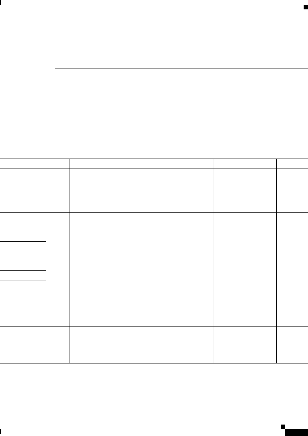
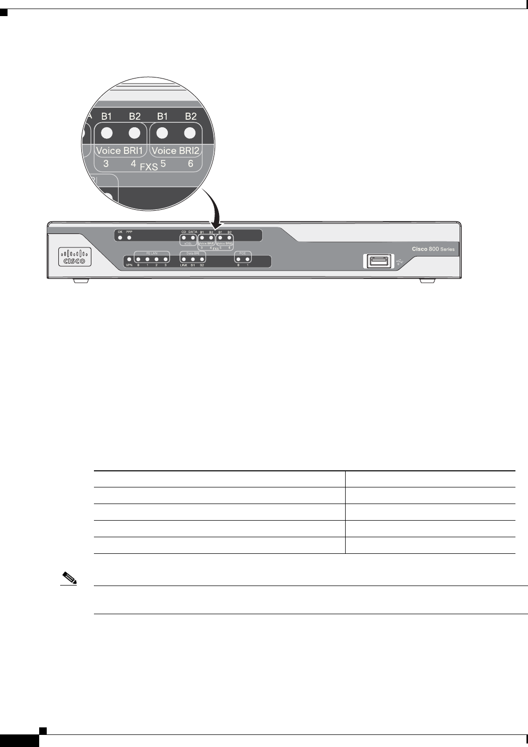
Shared LEDs on the Cisco 881-V and Cisco 887VA-V Voice and Data Routers
On the Cisco 881-V, Cisco 887VA-V, and Cisco 887VA-V-W routers, the BRI1, BRI2 and the FXS ports
share LED indicators. The following ports share an LED indicator:
•
BRI 1B1 channel and FXS 3
•
BRI 1B2 channel and FSX 4
•
BRI 2B1 channel and FXS 5
•
BRI 2 B2 channel and FXS 6
Because the LED indicators are shared, the LED illuminates (green) when either port is active. For
example, the LED indicator labeled BRI 1 B1 illuminates when either the BRI1 B1 channel is active or
when the FXS port is active. You can determine the activity status on each interface by using the
following commands.
•
For activity status on the FXS ports, use the show port summary command.
•
For activity status on the BRI ISDN port, use the show isdn status command.
Figure 1-19 shows a close-up view of the LED indicators.
xDSL Link Green On—DSL WAN Mode is selected and DSL training complete.
Blinking—DSL WAN Mode is selected but incomplete DSL Link Up state,
such as in-training, or controller “OFF,” or no cable attached to DSL connector.
Off—Device is powered off or GE WAN mode is selected.
GE ACT Green On—GE WAN interface is up.
Blinking—GE WAN activity (traffic in either direction).
Off—Device is powered off or GE WAN interface is down.
GE Mode Green On—GE WAN Mode is selected.
Off—Device is powered off or DSL WAN mode is selected.
1. xDSL = General term referring to various forms of DSL, including ADSL (asymmetric digital subscriber line) and VDSL (very-high-data-rate digital
subscriber line).
Table 1-5 LED Descriptions for the Cisco 866VAE, Cisco 867VAE, Cisco 866VAE-K9, and Cisco 867VAE-K9 ISRs (continued)
LED Activity Description
1-24
Cisco 860 Series, Cisco 880 Series, and Cisco 890 Series Integrated Services Routers Hardware Installation Guide
OL-16193-07
Chapter 1 Product Overview
Hardware Features
Figure 1-19 Close-up of the BRI and FXS LED Indicators
Memory
The Cisco 860 series, 880 series, and 890 series routers contain flash memory and main memory.
Flash Memory
The Cisco 860 series, 880 series, and 890 series ISRs use non-upgradable flash memory storage. The
onboard flash memory contains the Cisco IOS software image, the boot flash contains the ROMMON
boot code, and a separate non-volatile flash contains the cookie configuration.
Table 1-6 describes the default flash memory storage.
Note
Flash memory is not upgradable. An external USB flash memory module may be used if additional flash
memory is needed.
Main Memory
Table 1-7 describes the main onboard memory storage for different router models.
300149
Tabl e 1-6 Flash memory storage
Models Flash Memory Storage
Cisco 860 series and 880 series routers 128 MB
Cisco 880 series voice routers and Cisco 890 series routers 256 MB
Cisco 860VAE routers 8 MB boot flash, 128 MB for IOS
Cisco 860VAE-K9 64 MB boot flash and IOS

1-25
Cisco 860 Series, Cisco 880 Series, and Cisco 890 Series Integrated Services Routers Hardware Installation Guide
OL-16193-07
Chapter 1 Product Overview
Hardware Features
USB Port
The Cisco 880 series routers have a single Universal Serial Bus (USB 1.1-compliant) port located on the
front panel. The USB port provides connection for USB devices such as security tokens and flash
memory.
The Cisco 890 series routers have two USB 1.1-compliant ports located on the front panel.
The Cisco 860VAE series routers have one USB 2.0-compliant port located on the back panel. The Cisco
860VAE series router USB port does not support eToken.
Fan
Some router models do not have a fan, while other models have either one or two fans.
The fans spin at full speed, as a diagnostic aid, immediately after the router is powered up. After the
router has booted, the fans spin as fast as necessary to minimize fan noise while maintaining a safe
internal operating temperature.
Power over Ethernet Module
The Cisco 880 series ISRs can include an optional Power over Ethernet (PoE) module that provides
power to 802.3af-compliant devices connected to FE ports 0 and 1.
The Cisco 890 series ISRs can include an optional PoE module that provides power to 802.3af-compliant
devices connected to FE ports 0, 1, 2, and 3.
The PoE module is an option available only for the Cisco 880 series and 890 series ISRs and requires a
48-V external power adapter.
This function can be added to an 880 or 890 series router by installing the PoE adapter card in the router
and inserting the PoE 48-V external power adapter.
3G Cellular Data WAN Connectivity
The 3G (Evolution Data Only [EVDO], Universal Mobile Telecommunications Systems [UMTS])
cellular interface is intended for use as a backup data link, but it can also be used as a primary WAN data
link. The 3G technology is third-generation wide-area cellular technology that is used in voice telephony
and broadband wireless data in a mobile environment.
Tabl e 1-7 Main onboard memory storage
Models Onboard Memory Storage Expandibility
Cisco 860 series routers 256 MB Not expandable
Cisco 860VAE series routers 256 MB Not expandable
Cisco 880 series routers 256 MB
(expandable to 768 MB)
A memory expansion slot accommodates
a PC2-4200, 256-MB or 512-MB double
data rate 2 (DDR2) SODIMM, for a
maximum of 768 MB.
1-26
Cisco 860 Series, Cisco 880 Series, and Cisco 890 Series Integrated Services Routers Hardware Installation Guide
OL-16193-07
Chapter 1 Product Overview
Hardware Features
The Cisco 88xG models come with a 34-mm express card slot ready for use with a commercial 3G card
radio. The 3G express card slot is located on the front panel. For a list of supported 3G cards, see the
Cisco 880 Series Integrated Services Routers data sheet.
Wireless LAN Connectivity
The embedded Wi-Fi CERTIFIED™, 802.11a/b/g/n-compliant wireless AP is preinstalled in the router
as an optional feature. The Cisco 860 series routers support autonomous features and network
configurations. The Cisco 880 series and 890 series routers support both autonomous and unified
features and network configurations.
The wireless AP does not have an external console port. Use the router’s console port as described in
Chapter 3, “Connecting a Terminal or PC to the Console Port.” To configure the wireless device, use the
Cisco IOS command-line interface (CLI).
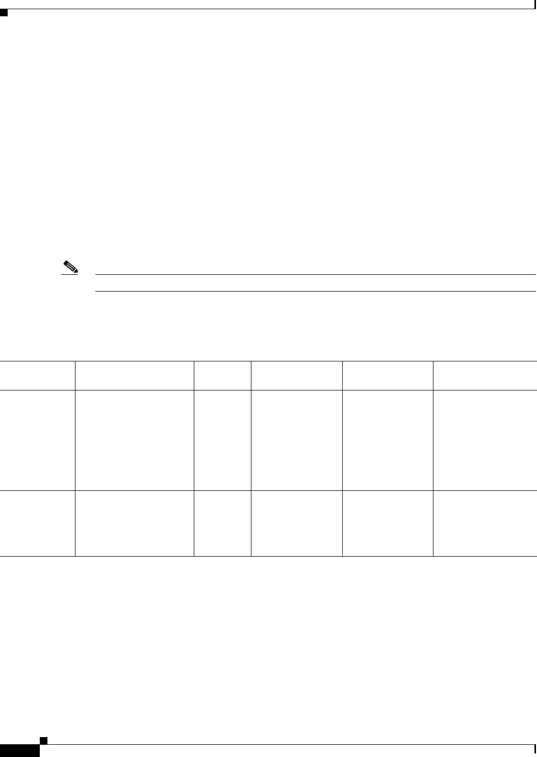
Table 1-8 describes the radios and antennas for the Cisco 860 series, 880 series, and 890 series routers.
Note
Cisco 860VAE ISRs do not support wireless LAN connectivity.
The 5-GHz radio operates in the Unlicensed National Information Infrastructure (UNII) 1, 2, 3, 5-GHz
frequency bands.
Tabl e 1-8 Wireless Device Radios and Antennas
Radio Module Platform
Radio
Band
Maximum Data
Throughput
1
1. Actual data rate is highly dependent on your wireless environment.
Mode Antenna
Single-band
802.11b/g/n
draft 2.0 radio
module
Cisco 860 and 880 series
routers
Note
Cisco 860VAE
ISRs do not
support wireless
LAN connectivity.
2.4 GHz Up to 100 Mb/s Cisco 860 series:
autonomous only
Cisco 880 series:
autonomous and
unified
Three captive 2-dBi
omnidirectional dipole
antennas
Dual-band
simultaneous
802.11a/n and
802.11b/g/n
radio module
Cisco 890 2.4 GHz
and 5 GHz
100 Mb/s per radio,
up to 200 Mb/s
total
Autonomous and
unified
Three dual-band,
removable,
2.4-GHz/5-GHz
omnidirectional dipole
RP-TNC antenna
2
2. The antennas require some minor installation. They must be screwed onto the RP-TNC antenna connectors on the I/O side of the chassis. See the following
document on Cisco.com for feature information:
.http://www.cisco.com/en/US/docs/routers/access/wireless/hardware/notes/antdip.html
1-27
Cisco 860 Series, Cisco 880 Series, and Cisco 890 Series Integrated Services Routers Hardware Installation Guide
OL-16193-07
Chapter 1 Product Overview
Hardware Features
Supported Cisco Radio Antennas
The Cisco 890 series ISRs come with three removable dipole antennas that can be replaced using the
Cisco approved antenna extenders listed in Table 1-9.
Note
Cisco supports only the antennas listed in Table 1-9 with the Cisco 890 series dual-band radio module.
Small Form-Factor Pluggable Port
The SFP port supports auto-media-detection, auto-failover, and remote fault indication (RFI), as
described in the IEEE 802.3ah specification.
See the Cisco 892F data sheet for a list of supported SFPs.
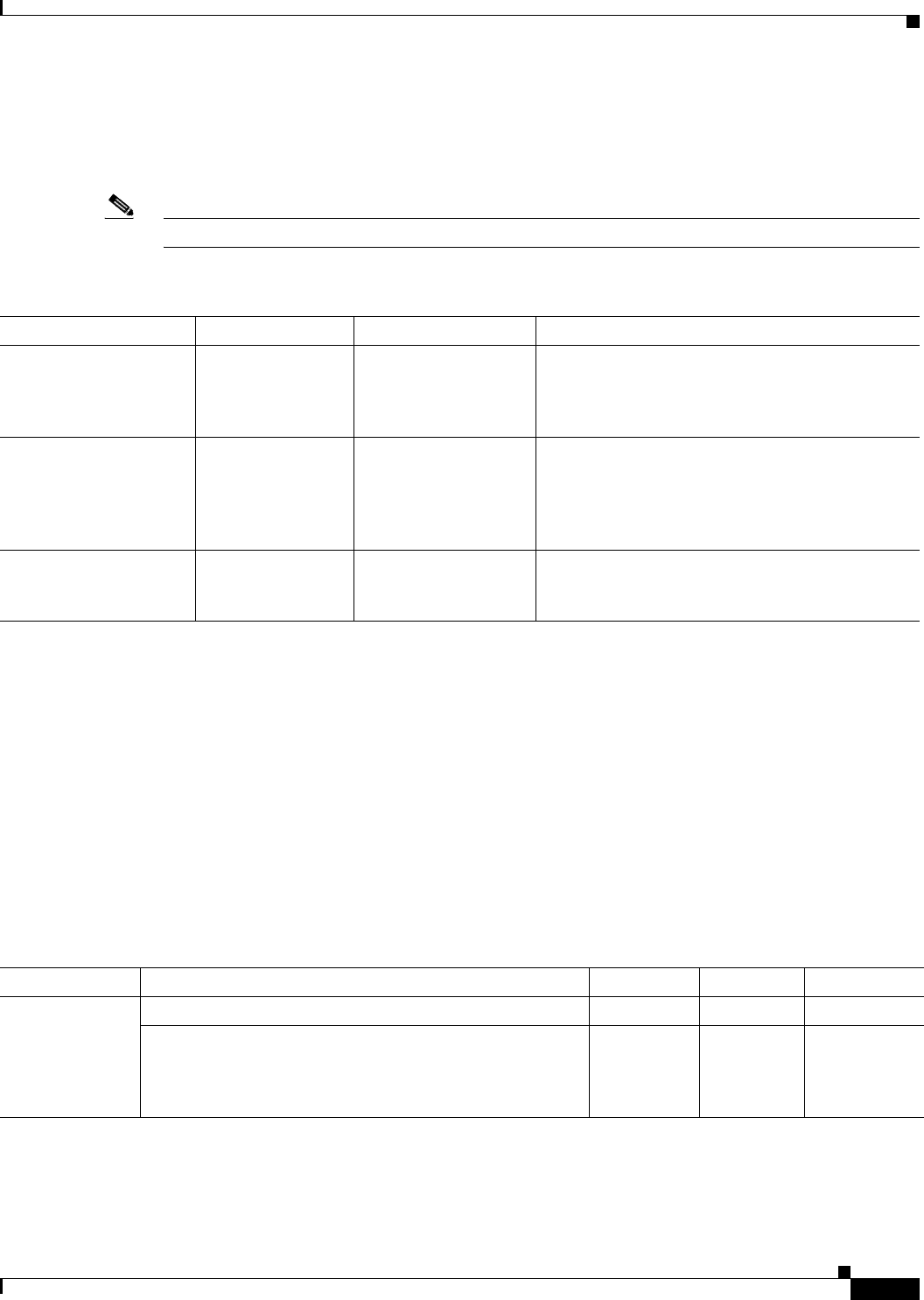
Feature Summary
Table 1-10 summarizes the hardware features available in the Cisco 860 series, Cisco 880 series, and
Cisco 890 series ISRs.
Tabl e 1-9 Cisco Antennas Supported on the Cisco 890 Series ISRs
Cisco Part Number Antenna Type Maximum Gain Description
AIR-ANTM2050D-R Omnidirectional 2.0 dBi at 2.4 GHz
5.0 dBi at 5 GHz
This is the default antenna. It is a swivel-mount
dipole dual-band blade antenna. For more
information, see Cisco Multiband Swivel-Mount
Dipole Antenna (AIR-ANTM2050D-R).
AIR-ANTM4050V-R Omnidirectional 4.0 dBi at 2.4 GHz
5.0 dBi at 5 GHz
Ceiling-mount dual-band antenna. This antenna
has a clip that allows it to be mounted on a
drop-ceiling cross member. For more information,
see Cisco Multiband Diversity Omnidirectional
Ceiling-Mount Antenna.
AIR_ANTM5560P-R Patch 5.5 dBi at 2.4 GHz
6.0 dBi at 5 GHz
Wall-mount dual-band antenna. For more
information, see Cisco Multiband Wall-Mount,
Corner-Mount, or Mast-Mount Antenna.
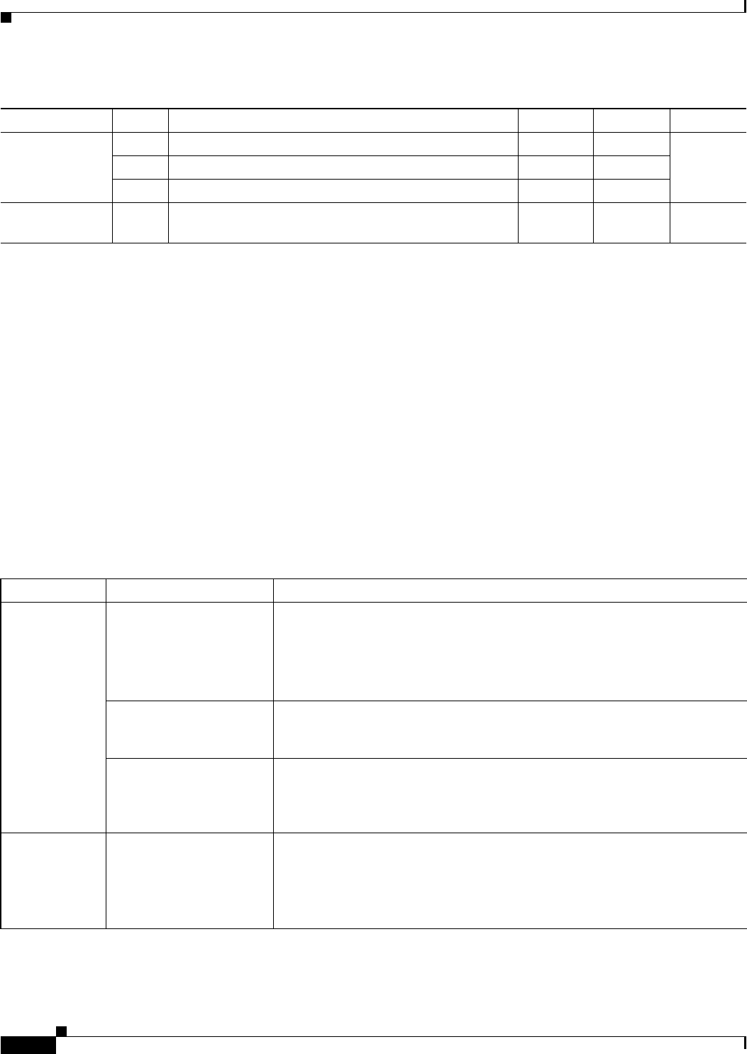
Tabl e 1-10 Hardware Features Available in Cisco 860 Series, Cisco 880 Series, and Cisco 890 Series ISRs
Feature Description 860 Series 880 Series 890 Series
Reset button Resets the router configuration to the factory default. All models All models All models
Resets the router configuration to customer configuration. 866VAE,
867VAE,
866VAE-K9,
867VAE-K9
— —

1-28
Cisco 860 Series, Cisco 880 Series, and Cisco 890 Series Integrated Services Routers Hardware Installation Guide
OL-16193-07
Chapter 1 Product Overview
Hardware Features
FE
1
built-in
switch ports
Provides connection to 10/100BASE-T (10/100-Mbps)
Fast Ethernet networks. The autosensing function in these
routers eliminates the need for a crossover cable and enables
the router to detect MDI
2
or MDIX
3
in any other PC or hub
with a straight-through cable or a crossover cable.
All models All models All models
GE
4
built-in
switch port
Provides connection to 10/100/1000BASE-T
(10/100/1000-Mbps) Gigabit Ethernet networks. The
autosensing function in these routers eliminates the need for
a crossover cable and enables the router to detect MDI
5
or
MDIX
6
in any other PC or hub with a straight-through cable
or a crossover cable.
866VAE-K9,
867VAE-K9
— —
Console or AUX
port
Provides a connection to the terminal or PC for software
configuration or troubleshooting. The console port may be
configured as a virtual auxiliary port for dial backup and
remote management. The Cisco 890 series routers have
separate console and auxiliary ports.
All models All models All models
Security features Provides support for VPNs
7
, Cisco IOS Firewall, and
IPSec
8
. The Cisco 880 series routers also provide URL
filtering.
861, 867,
866VAE-K9,
867VAE-K9
All models All models
Embedded
wireless AP
The wireless AP is Wi-Fi CERTIFIED™
802.11a/b/g/n-compliant. The Cisco 860 series and
880 series routers contain a single 802.11b/g/n radio. The
Cisco 890 series routers contain dual 802.11b/g/n and
802.11a/n radios.
Wireless
models
802.11b/g/n
Wireless
models
802.11b/g/n
Wireless
models
802.11b/g/n
and 802.11a/n
FE WAN port Provides connection to 10/100BASE-T. Can be connected to
other network devices, such as a cable modem, an xDSL
9
modem, or router. The router is capable of bridging and
multiprotocol routing between the LAN and WAN ports.
861 881 All models
GE WAN port 10/100/1000 GE WAN Port. 866VAE,
867VAE,
866VAE-K9,
867VAE-K9
—All models
VDSLoPOTS
10
port
Provides connection to a VDSL network. —887V —
ADSLoPOTS Provides ADSL connection over basic telephone service
with Annex A and Annex B ITU G. 992.1 (ADSL), G.992.3
(ADSL2), and G.992.5 (ADSL).
— — —
ADSLoISDN Provides ADSL connection over ISDN. — — —
DSL Multi-mode
(VDSL and
ADSL2/2+)
Provides ADSL2/2+ or VDSL connection over POTS or
ISDN (ISDN on 886VA only).
866VAE,
867VAE,
866VAE-K9,
867VAE-K9
886VA,
887VA,887
VA - M
—
Table 1-10 Hardware Features Available in Cisco 860 Series, Cisco 880 Series, and Cisco 890 Series ISRs (continued)
Feature Description 860 Series 880 Series 890 Series

1-29
Cisco 860 Series, Cisco 880 Series, and Cisco 890 Series Integrated Services Routers Hardware Installation Guide
OL-16193-07
Chapter 1 Product Overview
Hardware Features
Real-time clock
(RTC)
RTC provides nonvolatile date and time when the router is
powered on. The RTC is used for verifying the validity of
the Certification Authority stored on the router. It is backed
up by a nonreplaceable lithium battery.
866VAE,
867VAE,
866VAE-K9,
867VAE-K9
All models All models
USB port Supports USB 1.1. Provides connection for USB devices
such as security tokens and flash memory.
The Cisco 880 series routers have a single USB port; the
Cisco 890 series routers have two USB ports.
Cisco 860VAE series routers have one USB 2.0 port on the
rear panel for temporary installation of a Cisco-approved
USB memory device for maintenance purposes only. The
port supports only USB 2.0. Refer to the product datasheet
for the list of supported USB flash memory devices.
Note
The Cisco 860VAE series router USB port does not
support eToken.
866VAE,
867VAE,
866VAE-K9,
867VAE-K9
All models All models
PoE
11
(Optional) Provides power for 802.3af-compliant devices
(such as phones) that are connected to the router.
The Cisco 880 series routers support a 2-port PoE module;
the Cisco 890 series routers support a 4-port PoE module.
—Models with
PoE
Models with
PoE
G. S H D S L
12
port Provides 2-wire or 4-wire connection to a G.SHDSL
network.
—888 —
3G
13
card slot Provides backup data link. —3G models —
Dying gasp Detects when the router is losing power, and sends a
power-fail signal to warn the DSLAM
14
about the
impending line drop.
866VAE,
867VAE,
866VAE-K9,
867VAE-K9
xDSL
models
—
Data BRI port Provides backup and remote management functions by
connecting to the ISDN service provider if the main VDSL
or G.SHDSL link fails.
—xDSL
models,
except for
the 3G and
SRST
15
models
892
V. 9 2 mo d em Provides dial backup and remote management functions if
the main WAN link fails.
— — 891
FXO
16
port An FXO interface connects local calls to a central office or
PBX. This is the interface a standard telephone provides.
—881 SRST —
FXS
17
/DID
18
port
An FXS interface connects directly to a standard telephone,
fax machine, or similar device. This interface supplies
ringing voltage and dial tone to the station.
—SRST
models
—
Table 1-10 Hardware Features Available in Cisco 860 Series, Cisco 880 Series, and Cisco 890 Series ISRs (continued)
Feature Description 860 Series 880 Series 890 Series

1-30
Cisco 860 Series, Cisco 880 Series, and Cisco 890 Series Integrated Services Routers Hardware Installation Guide
OL-16193-07
Chapter 1 Product Overview
Hardware Features
BRI voice port The ISDN BRI S/T voice interface provides a client-side
(TE) ISDN S/T physical interface for connection to an NT1
device that terminates an ISDN telephone network.
—887V —
SFP
19
port Supports auto-media-detection, auto-failover, and remote
fault indication (RFI), as described in the IEEE 802.3ah
specification.
See the Cisco 892F data sheet for a list of supported SFPs.
— — 892F models
1. FE = Fast Ethernet.
2. MDI = media-dependent interface in normal mode.
3. MDIX = media-dependent interface in crossover mode.
4. GE = Gigabit Ethernet.
5. MDI = media-dependent interface in normal mode.
6. MDIX = media-dependent interface in crossover mode.
7. VPN = Virtual Private Network.
8. IPsec = IP security.
9. xDSL = General term referring to various forms of DSL, including ADSL (asymmetric digital subscriber line), VDSL (very-high-data-rate digital
subscriber line), and G.SHDSL.
10. VDSLoPOTS = very-high-data-rate digital subscriber line 2 over plain old telephone service.
11. PoE = Power over Ethernet. This function can be added to an 880 or 890 series router by installing the PoE adapter card in the router and inserting the
PoE 48-V external power adapter.
12. G.SHDSL = (global industry standard) symmetrical high-speed DSL.
13. 3G = Third-Generation.
14. DSLAM = digital subscriber line access multiplexer.
15. SRST = Survivable Remote Site Telephony.
16. FXO = Foreign Exchange Office.
17. FXS = Foreign Exchange Station.
18. DID = Direct Inward Dialing.
19. SFP = small-form-factor pluggable.
Table 1-10 Hardware Features Available in Cisco 860 Series, Cisco 880 Series, and Cisco 890 Series ISRs (continued)
Feature Description 860 Series 880 Series 890 Series

CHAPTER
2-1
Cisco 860 Series, Cisco 880 Series, and Cisco 890 Series Integrated Services Routers Hardware Installation Guide
OL-16193-07
2
Installing the Router
This chapter describes the equipment and the procedures for successfully installing the Cisco 860 series,
880 series, and 890 series Integrated Services Routers (ISRs), and contains the following sections:
•
Equipment, Tools, and Connections, page 2-1
•
Installing the Router, page 2-3
Note
For compliance and safety information, see the Regulatory Compliance and Safety Information
Roadmap that ships with the router and the Regulatory Compliance and Safety Information for Cisco 800
Series and SOHO Series Routers.
Warning
Read the installation instructions before connecting the system to the power source.
Statement
1004
Warning
Only trained and qualified personnel should be allowed to install, replace, or service
this equipment.
Statement 1030
Warning
Ultimate disposal of this product should be handled according to all national laws and
regulations.
Statement 1040
Equipment, Tools, and Connections
This section describes the equipment, tools, and connections necessary for installing your Cisco 860
series, 880 series, and 890 series ISRs. It contains the following topics:
•
Items Shipped with your Router, page 2-2
•
Additional Items, page 2-2
•
Connections, page 2-3
•
Ethernet Devices, page 2-3
2-2
Cisco 860 Series, Cisco 880 Series, and Cisco 890 Series Integrated Services Routers Hardware Installation Guide
OL-16193-07
Chapter 2 Installing the Router
Equipment, Tools, and Connections
Items Shipped with your Router
Unpack the box and verify that all items listed on the invoice were shipped with the router.
Table 2-1 lists the items and their quantities that are shipped with each router model.
Additional Items
The following items are not shipped with the router but are required for installation:
•
ESD-preventive cord and wrist strap.
•
Screws for mounting the router on a wall:
–
Two number-10 wood screws (round- or pan-head) with number-10 washers, or two number-10
washer-head screws, for mounting on a wall stud. The screws must be long enough to penetrate
at least 3/4 in. (20 mm) into the supporting wood or metal wall stud.
–
Two number-10 wall anchors with washers, for mounting the router on a hollow-wall.
•
Wire crimper for chassis grounding.
•
Wire for connecting the chassis to an earth ground:
–
AWG 14 (2 mm
2
) or larger wire for NEC-compliant chassis grounding.
–
AWG 18 (1 mm
2
) or larger wire for EN/IEC 60950–compliant chassis grounding.
•
A ring terminal with an inner diameter of 1/4 in. (5 to 7 mm), for NEC-compliant chassis grounding.
•
Ethernet cables for connecting to the Fast Ethernet (FE) WAN and LAN ports.
Tabl e 2-1 Items and Their Quantities That Are Shipped with the Cisco 860 Series, Cisco 880 Series, and
Cisco 890 Series ISRs
Item
Cisco 860
Series
Routers
Cisco
860VAE
Series
Routers
1
1. By default, no cables are shipped with Cisco 860VAE models unless requested through the dynamic configuration tool.
Cisco 880
Series
Routers
Cisco 890
Series
Routers
Straight-through RJ-45 Ethernet cable 1 — 1 1
ADSL RJ-11-to-RJ-11 straight-through cable ————
RJ-11 DSL
2
cable
2. DSL = digital subscriber line.
1
3
3. Shipped with Cisco 867 models only.
n/a 1
4
4. Shipped with Cisco 886, 887, 887M, and 886-J models only.
1
DSL RJ-45-to-dual-RJ-11 breakout cable —n/a 1
5
5. Shipped with Cisco 888E models only.
—
RJ-45-to-DB-9 console cable 1 — 1 1
External 12 VDC power supply adapter 1111
AC power supply cable with cable retention clip 1111
Cisco Configuration Professional (Cisco CP) CD
6
6. Cisco CP is optional by order and available only on some SKUs.
1111

2-3
Cisco 860 Series, Cisco 880 Series, and Cisco 890 Series Integrated Services Routers Hardware Installation Guide
OL-16193-07
Chapter 2 Installing the Router
Installing the Router
Connections
Obtain a broadband or Ethernet connection from your service provider.
Ethernet Devices
Identify the Ethernet devices that you will connect to the router: hub, servers, and workstations or PCs.
Ensure that each device has a network interface card (NIC) for connecting to Ethernet ports.
•
If you plan to configure the software using Cisco IOS commands through the console port, provide
an ASCII terminal or a PC that is running terminal emulation software to connect to the console port.
•
If you plan to connect a modem, provide the modem and modem cable.
•
If you plan to use the Data BRI port, provide an NT1 device and an ISDN S/T cable.
•
If you plan to use the cable-lock feature, provide a Kensington or equivalent locking cable.
Installing the Router
This section describes how to install the Cisco 860 series, 880 series, and 890 series ISRs. These routers
can either be installed on a table top or other flat horizontal surface or be mounted on a wall. The
Cisco 890 series ISRs may be mounted in a rack. This section also describes how to attach WLAN
antennas to the Cisco 890 series routers. This section contains the following topics:
•
Warnings, page 2-3
•
Installing Antennas, page 2-4
•
Installing on a Table, page 2-7
•
Mounting on a Wall, page 2-7
•
Installing in a Rack, page 2-10
•
Installing the Router Ground Connection, page 2-11
Warnings
Warning
This equipment needs to be grounded. Use a green and yellow 12 to 14 AWG ground wire to
connect the host to earth ground during normal use.
Statement 242
Warning
This equipment must be grounded. Never defeat the ground conductor or operate the equipment
in the absence of a suitably installed ground conductor. Contact the appropriate electrical
inspection authority or an electrician if you are uncertain that suitable grounding is available.
Statement 1024
2-4
Cisco 860 Series, Cisco 880 Series, and Cisco 890 Series Integrated Services Routers Hardware Installation Guide
OL-16193-07
Chapter 2 Installing the Router
Installing the Router
Warning
This unit is intended to be mounted on a wall. Please read the wall mounting instructions
carefully before beginning installation. Failure to use the correct hardware or to follow the
correct procedures could result in a hazardous situation to people and damage to the system.
Statement 248
Note •
Do not stack anything on top of the router.
•
Do not cover or obstruct the router vents located on both sides and top of the routers; otherwise,
overheating could occur and cause damage to the router.
•
Place router in ventilated area to avoid local air heating.
Caution
Do not cover or obstruct the router vents located on both sides of the router; otherwise, overheating could
occur and cause damage to the router.
Caution
Do not place anything on top of the router that weighs more than 10 pounds (4.5 kilograms), and do not
stack routers on a desktop. Excessive weight on top of the router could damage the chassis.
Caution
Do not install the router or power supplies next to a heat source of any kind, including heating vents.
Caution
The top surface of the router is hot since heat is dissipated through the top. Do not keep any object in
direct contact with the surface for a prolonged period.
Installing Antennas
The Cisco 890 series wireless routers have three reverse-polarity threaded Neill-Concelman (RP-TNC)
connectors on the back panel. The antennas that are shipped with the router are dual-band 2.4-GHz to
5-GHz omnidirectional dipole antennas.
Warning
All wireless LAN products in the 5.2/5.3GHz band cannot be used outdoors. Use the product only
indoors.
Statement 372
Note
Before you install the Cisco 890 series wireless router on a table, wall, or rack, connect the antennas to
the back panel. It is difficult to attach the antennas after the router is installed.

2-5
Cisco 860 Series, Cisco 880 Series, and Cisco 890 Series Integrated Services Routers Hardware Installation Guide
OL-16193-07
Chapter 2 Installing the Router
Installing the Router
To attach the radio antennas to your wireless router, follow these steps:
Step 1
Manually screw the antennas tight to the RP-TNC connectors on the back of the router.
Figure 2-1 Attaching Antennas to the Router
Step 2
Orient the antennas. For optimum wireless performance, the antennas should be perpendicular with
respect to the floor.
a.
If the router is being mounted on a desk, orient the antennas straight up.
b.
If the router is being mounted on a wall, orient the antennas perpendicular to the floor as shown in
Figure 2-2 and Figure 2-3.
272486
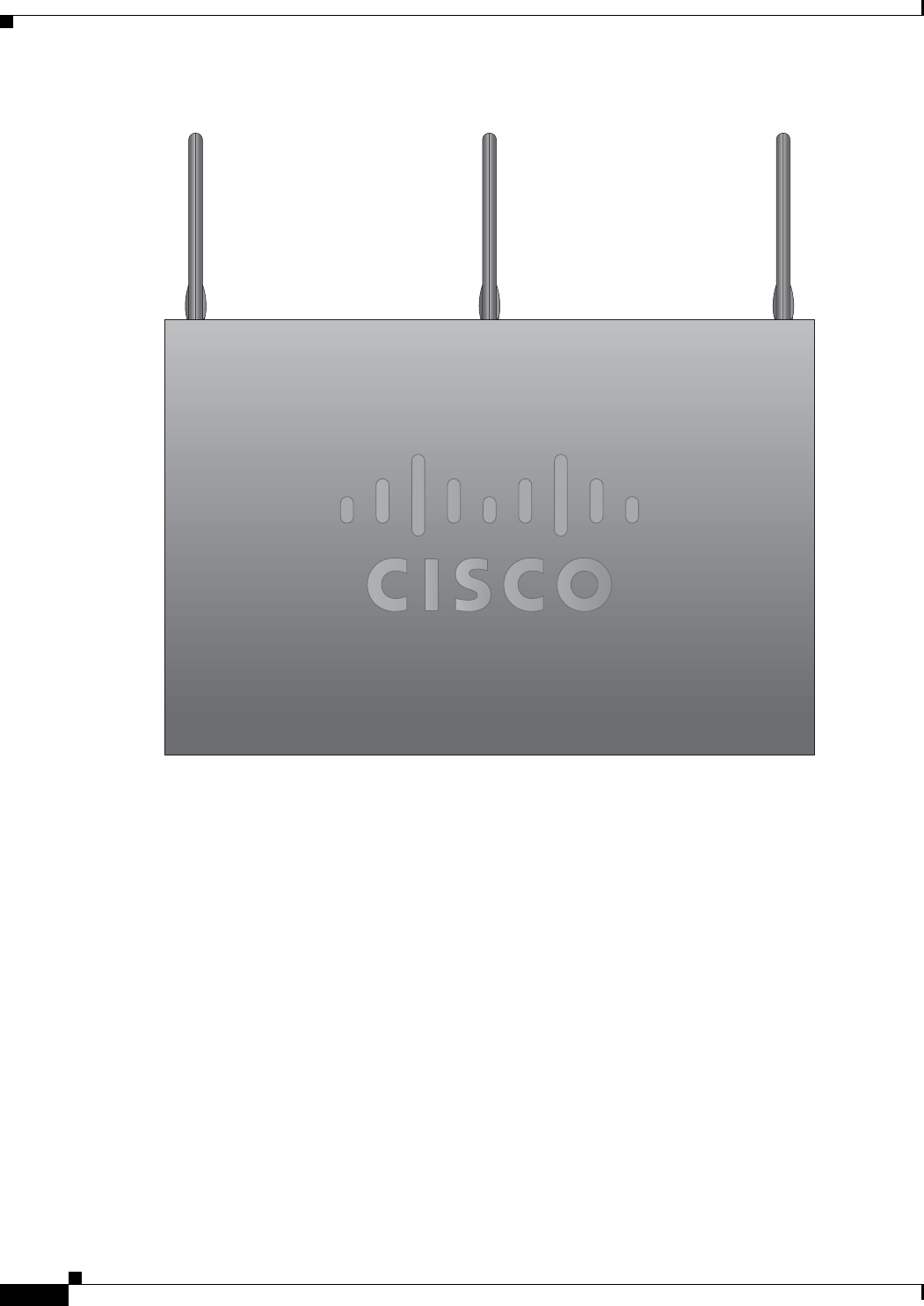
2-6
Cisco 860 Series, Cisco 880 Series, and Cisco 890 Series Integrated Services Routers Hardware Installation Guide
OL-16193-07
Chapter 2 Installing the Router
Installing the Router
Figure 2-2 Antennas Oriented Vertically Up
2
74774
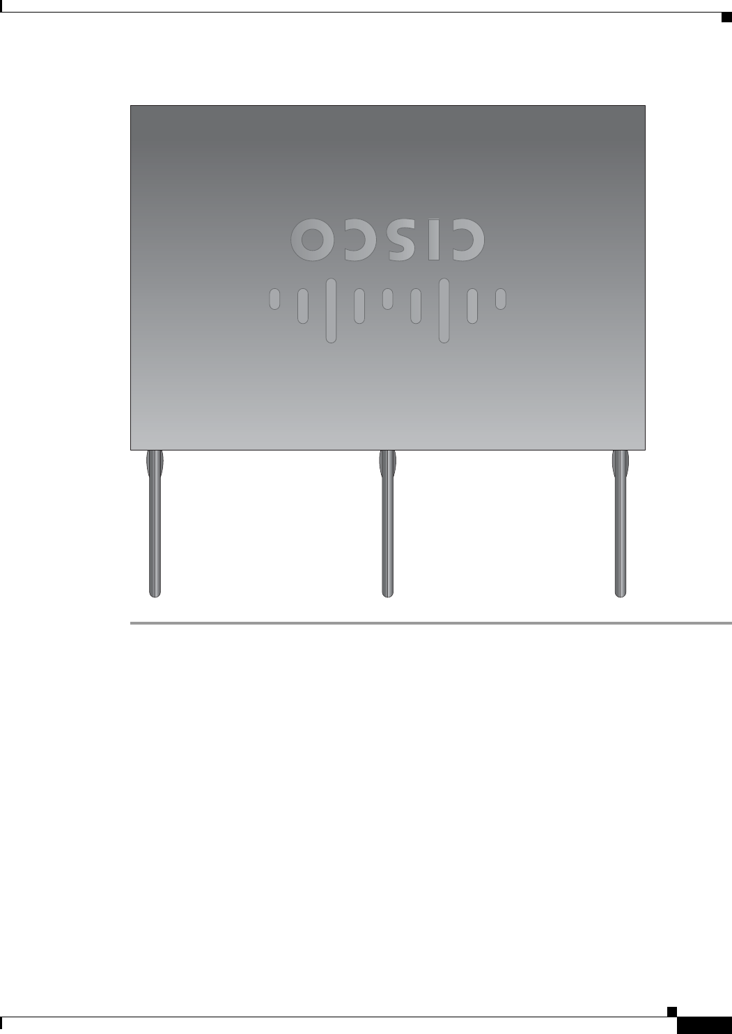
2-7
Cisco 860 Series, Cisco 880 Series, and Cisco 890 Series Integrated Services Routers Hardware Installation Guide
OL-16193-07
Chapter 2 Installing the Router
Installing the Router
Figure 2-3 Antennas Oriented Vertically Down
Installing on a Table
To install the router on a table or other flat horizontal surface, firmly place the router on a table or other
horizontal surface. Keep at least 1 inch (2.5 centimeters) of clear space beside the cooling inlet and
exhaust vents.
Connect the chassis to a reliable earth ground. For the chassis ground connection procedures, see the
“Installing the Router Ground Connection” section on page 2-11.
Mounting on a Wall
The Cisco 860 series, 880 series, and 890 series ISRs have mounting holes on the bottom of the chassis
for mounting the unit on a wall or other vertical surface.
The mounting holes are bidirectional. You can hang the router with the front bezel facing upward or
downward.
2
74775
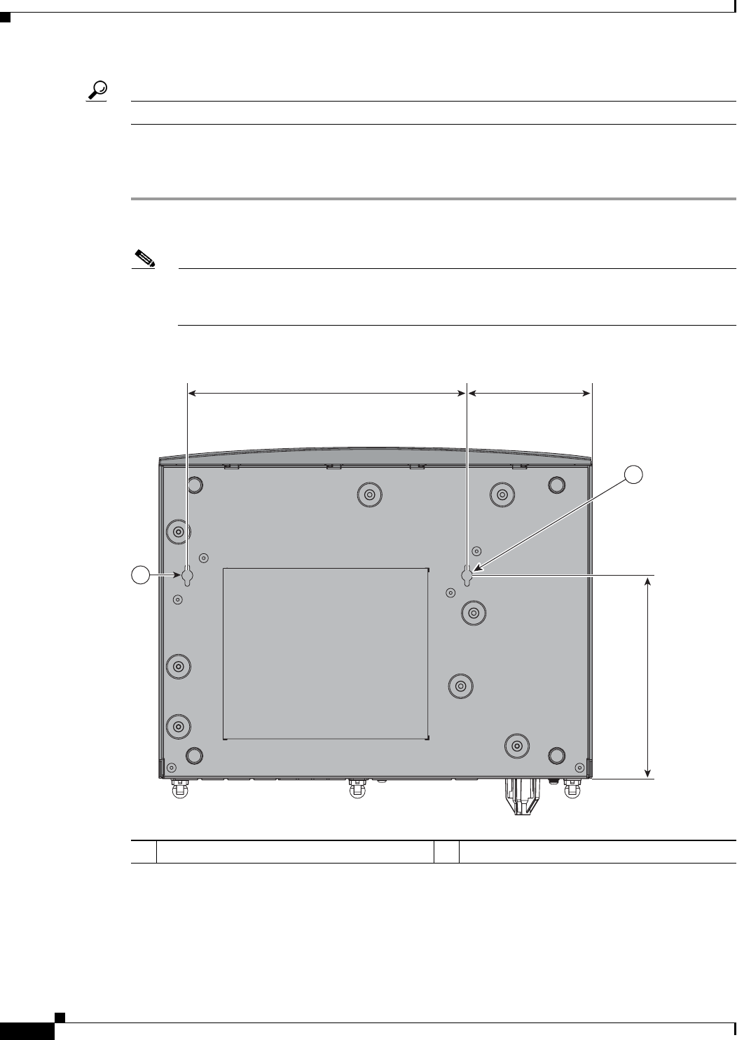
2-8
Cisco 860 Series, Cisco 880 Series, and Cisco 890 Series Integrated Services Routers Hardware Installation Guide
OL-16193-07
Chapter 2 Installing the Router
Installing the Router
Tip
When choosing a location for wall-mounting the router, consider cable limitations and wall structure.
To mount the router on a wall, follow these steps:
Step 1
Determine the required distance between mounting holes on the router. Figure 2-4 shows the wall-mount
holes located on the underside of the router.
Note
For most router models, the distance between mounting holes is 8.2 inches (208 mm), as shown
in Figure 2-4. For the Cisco 866 and Cisco 867 models, the distance is 7.85 inches (199 mm).
Ver i f y t h e re q u i re d d i st a n c e before drilling the holes.
Figure 2-4 Wall-mount Holes on the Underside of the Router
Step 2
Insert the screws, with anchors, into the wall. Leave 1/8 inch (0.32 cm) between the screw head and the
wall. See Figure 2-5.
Step 3
Hang the router on the screws, and place the power adapter on a nearby horizontal surface. See
Figure 2-5.
1Wall-mount holes
2
31987
1
3.673 in.8.200 in.
5.961 in.
1
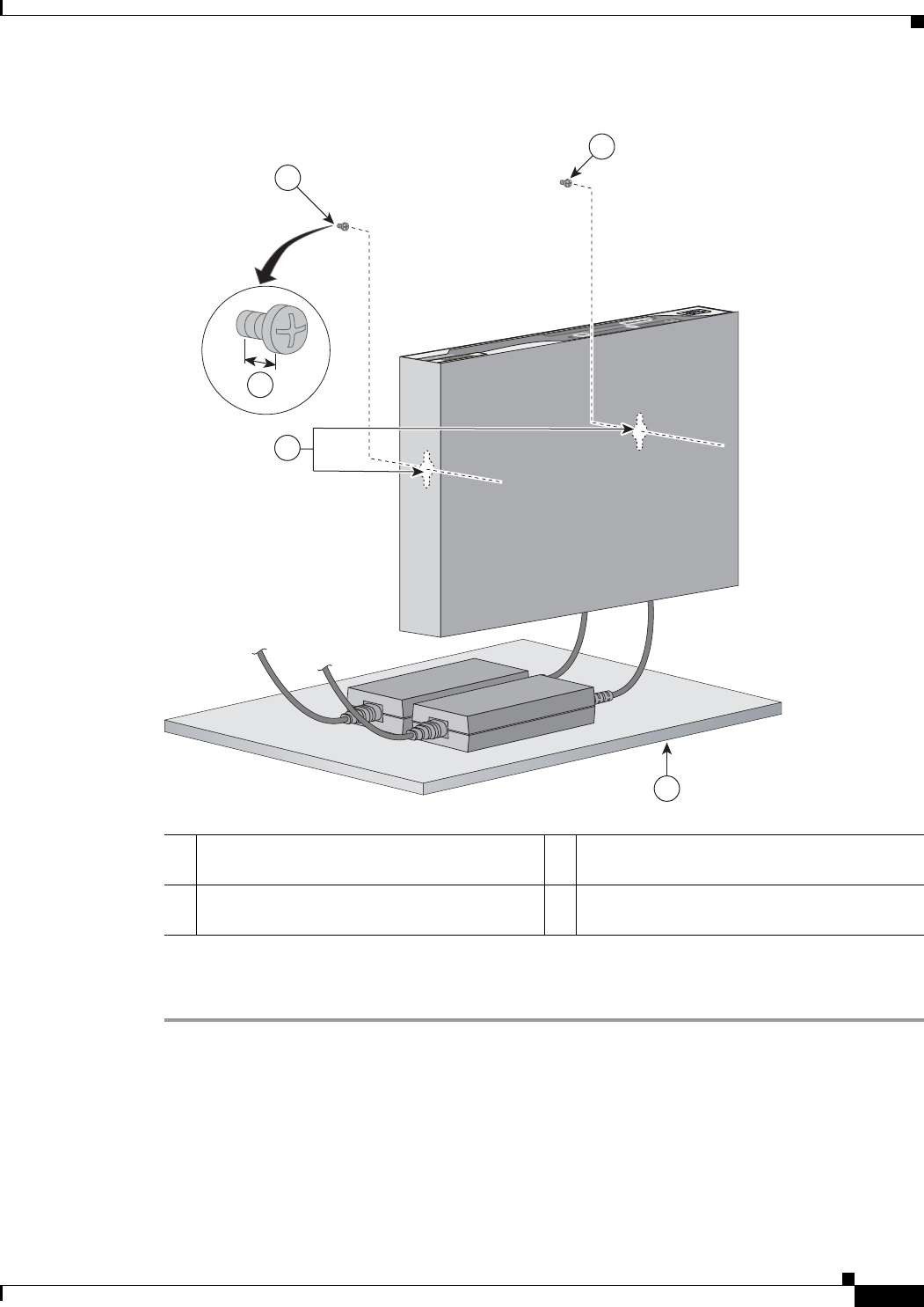
2-9
Cisco 860 Series, Cisco 880 Series, and Cisco 890 Series Integrated Services Routers Hardware Installation Guide
OL-16193-07
Chapter 2 Installing the Router
Installing the Router
Figure 2-5 Router Mounted on the Wall
Step 4
Connect the chassis to a reliable earth ground. For the chassis ground connection procedures, see the
“Installing the Router Ground Connection” section on page 2-11.
1Two number-10 wood screws mounted on the
wall
3Horizontal surface on which to place the
power adapter
2Wall-mount holes 4Distance between the screw head and the wall,
1/8 in. (0.32 cm)
231982
4
2
1
1
3
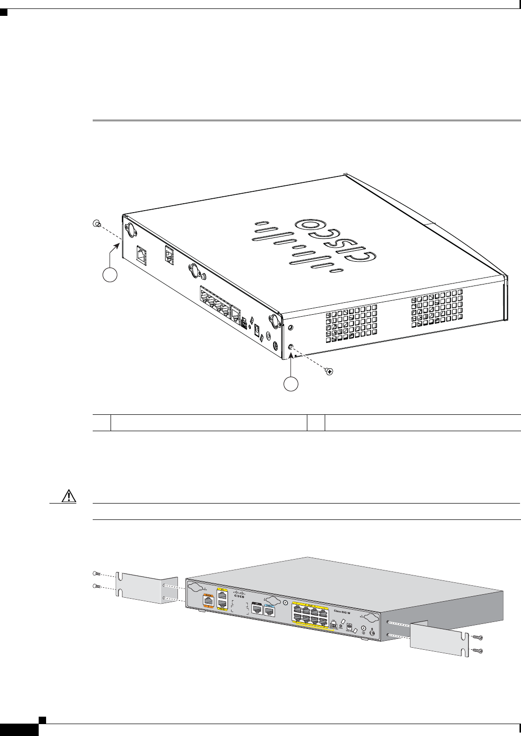
2-10
Cisco 860 Series, Cisco 880 Series, and Cisco 890 Series Integrated Services Routers Hardware Installation Guide
OL-16193-07
Chapter 2 Installing the Router
Installing the Router
Installing in a Rack
The Cisco 890 series ISRs can be mounted in a rack. To install a Cisco 890 series ISR in a rack, follow
these steps:
Step 1
Remove the screws shown in Figure 2-6.
Figure 2-6 Screw Location
Step 2
Using the screws provided, attach the rack-mount brackets to the Cisco 890 series ISR chassis as shown
in Figure 2-7. Use two screws on each side. Use a number 2 Phillips screwdriver to install the bracket
screws on both sides of the chassis.
Caution
Do not over torque the screws. The recommended torque is 6 to 8 in-lb (0.7 to 0.9 N-m).
Figure 2-7 Attaching the Rack-mount Brackets to the Cisco 890 Series ISR
1Screws
278159
1
1
272484

2-11
Cisco 860 Series, Cisco 880 Series, and Cisco 890 Series Integrated Services Routers Hardware Installation Guide
OL-16193-07
Chapter 2 Installing the Router
Installing the Router
Warning
To prevent bodily injury when mounting or servicing this unit in a rack, you must take special
precautions to ensure that the system remains stable. The following guidelines are provided to
ensure your safety:
--
This unit should be mounted at the bottom of the rack if it is the only unit in the rack.
--
When mounting this unit in a partially filled rack, load the rack from the bottom to the top with the heaviest
component at the bottom of the rack.
--
If the rack is provided with stabilizing devices, install the stabilizers before mounting or servicing the unit in
the rack.
Statement 1006
Caution
Chassis installation must allow unrestricted airflow for chassis cooling.
Step 3
Using two screws for each side (supplied with the rack), attach the Cisco 890 series ISR with rack-mount
brackets to a 19-inch rack. Start with the lower pair of screws first, resting the brackets on the lower
screws while you insert the upper pair of screws.
Note
Be sure to leave space above and below each unit in a rack to allow for cooling air circulation.
Tip
The screw slots in the brackets are spaced to line up with every second pair of screw holes in the
rack. When the correct screw holes are used, the small threaded holes in the brackets line up with
unused screw holes in the rack. If the small holes do not line up with the rack holes, you must
raise or lower the brackets to the next rack hole.
Step 4
Place the power adapter on a nearby horizontal surface.
Step 5
Connect the chassis to a reliable earth ground. For the chassis ground connection procedures, see the
“Installing the Router Ground Connection” section on page 2-11.
Installing the Router Ground Connection
The router must be connected to a reliable earth ground. Install the ground wire in accordance with local
electrical safety standards.
•
For NEC-compliant grounding, use size 14 AWG (2 mm
2
) or larger copper wire and a ring terminal
with an inner diameter of 1/4 in. (5 to 7 mm).
•
For EN/IEC 60950–compliant grounding, use size 18 AWG (1 mm
2
) or larger copper wire.
To install the ground connection, follow these steps:
Step 1
Strip one end of the ground wire to the length required for the ground lug or terminal.
Step 2
Crimp the ground wire to the ground lug or ring terminal, using the wire crimper.
Step 3
Attach the ground lug or ring terminal to the chassis as shown in Figure 2-8. For a ground lug, use the
two provided screws with captive locking washers. For a ring terminal, use one of the screws provided.
Tighten the screws to a torque of 8 to 10 in-lb (0.9 to 1.1 N-m).
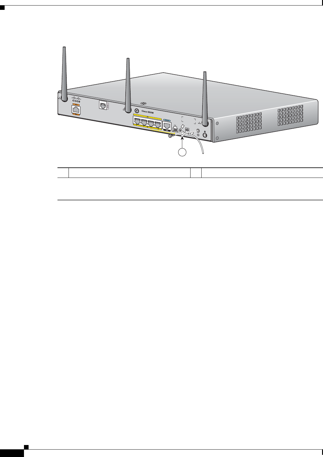
2-12
Cisco 860 Series, Cisco 880 Series, and Cisco 890 Series Integrated Services Routers Hardware Installation Guide
OL-16193-07
Chapter 2 Installing the Router
Installing the Router
Figure 2-8 Chassis Ground Connection Using Ring Terminal
Step 4
Connect the other end of the ground wire to a known reliable earth ground point at your site.
After you install and properly ground the router, you can connect the power wiring, the WAN and LAN
cables, and the cables for administrative access as required for your installation.
1Ring terminal
231981
1

CHAPTER
3-1
Cisco 860 Series, Cisco 880 Series, and Cisco 890 Series Integrated Services Routers Hardware Installation Guide
OL-16193-07
3
Connecting the Router
This chapter describes how to connect Cisco 860 series, Cisco 880 series, and Cisco 890 series
Integrated Services Routers (ISRs) to Ethernet devices, Power over Ethernet (PoE), and a network. The
chapter contains the following sections:
•
Preparing to Connect the Router, page 3-2
•
Connecting a PC, Server, or Workstation, page 3-3
•
Connecting a Phone, page 3-4
•
Connecting an External Ethernet Switch, page 3-5
•
Connecting the V.92 modem Port, page 3-6
•
Connecting a Terminal or PC to the Console Port, page 3-7
•
Connecting a Modem to the Auxiliary Port, page 3-8
•
Connecting the 3G Card, page 3-9
•
Installing the 3G Adapter for Extended Cable/Antenna, page 3-15
•
Connecting an FE Line to an FE WAN Port, page 3-21
•
Connecting an GE Line to an GE WAN Port, page 3-22
•
Connecting an xDSL Line, page 3-23
•
Connecting Power over Ethernet, page 3-25
•
Connecting the AC Adapter, page 3-26
•
Connecting an FXS Line, page 3-29
•
Connecting an FXO Line, page 3-31
•
Connecting a Voice ISDN BRI Line, page 3-32
•
Connecting a Small-form-factor Pluggable Module, page 3-33
•
Verifying Connections, page 3-37
Note
For compliance and safety information, see Regulatory Compliance and Safety Information Roadmap
that ships with the router and Regulatory Compliance and Safety Information for Cisco 800 Series and
SOHO Series Routers.

3-2
Cisco 860 Series, Cisco 880 Series, and Cisco 890 Series Integrated Services Routers Hardware Installation Guide
OL-16193-07
Chapter 3 Connecting the Router
Preparing to Connect the Router
Note
The illustrations in this chapter show a wireless router with antennas attached. Nonwireless routers do
not have antennas or antenna connectors on the back panel. However, the procedures for connecting
devices to the router are the same for both wireless and nonwireless routers.
Note
Depending on the features available for your router, some content in this chapter may not apply to your
router.
Preparing to Connect the Router
Before you connect the router to the devices, install the router according to the instructions in Chapter 2,
“Installing the Router.”
Preventing Damage to the Router
To prevent damage to your router, follow these guidelines when connecting devices to your router:
•
Turn off power to the devices and to the router until all connections are completed.
Caution
Do not turn on the devices until after you have completed all connections to the router.
•
Connect the color-coded cables supplied by Cisco to the color-coded ports on the back panel.
•
If you must supply your own cable, see Appendix A, “Technical Specifications,” for cabling
specifications. If this appendix does not provide specifications for a particular cable, we strongly
recommend ordering the cable from Cisco.
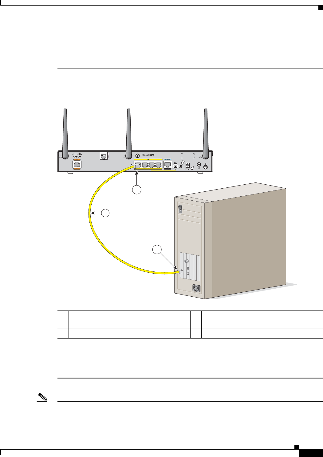
3-3
Cisco 860 Series, Cisco 880 Series, and Cisco 890 Series Integrated Services Routers Hardware Installation Guide
OL-16193-07
Chapter 3 Connecting the Router
Connecting a PC, Server, or Workstation
Connecting a PC, Server, or Workstation
To connect a PC (or other Ethernet devices) to an Ethernet switch port, follow these steps:
Step 1
Connect one end of the yellow Ethernet cable to an Ethernet switch port on the router. Figure 3-1 shows
a Cisco 888W router connected to a PC.
Figure 3-1 Connecting a Server, PC, or Workstation
Step 2
Connect the other end of the cable to the RJ-45 port on the network interface card (NIC) that is installed
in the PC, server, or workstation.
Step 3
(Optional) Connect additional servers, PCs, or workstations to the other Ethernet switch ports.
Note
Use the Cisco Configuration Express to configure the Internet connection settings. See
Cisco Configuration Professional Quick Start Guide for more information.
1Yellow Ethernet cable supplied with the
router
3RJ-45 port on the network interface card
2Ethernet switch port on the router
3
2
231989
1
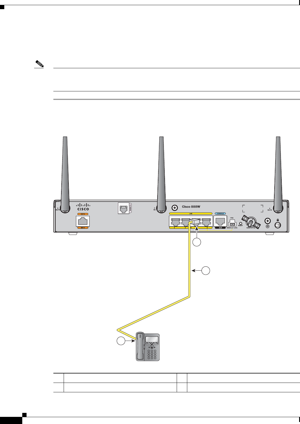
3-4
Cisco 860 Series, Cisco 880 Series, and Cisco 890 Series Integrated Services Routers Hardware Installation Guide
OL-16193-07
Chapter 3 Connecting the Router
Connecting a Phone
Connecting a Phone
To connect an 802.3af-compliant phone to an Ethernet switch port, follow these steps:
Note
A power source must be provided for the phone to function. This can be done in two ways, the phone
can be powered via the PoE function using the PoE enabled Ethernet ports or by using an external AC
power source connected to the phone.
Step 1
Connect one end of the yellow Ethernet cable to Ethernet switch port 0 or port 1 on the router. Figure 3-2
shows a Cisco 888W router connected to a phone.
Figure 3-2 Connecting a Phone
1Yellow Ethernet cable 3RJ-45 port on a phone
2Ethernet switch port 1 on the router
3
2
270551
1
12
ABC
3
DEF
45
JKLGHI
6
MNO
78
TUVPQRS
9
WXYZ
*0
OPER
#
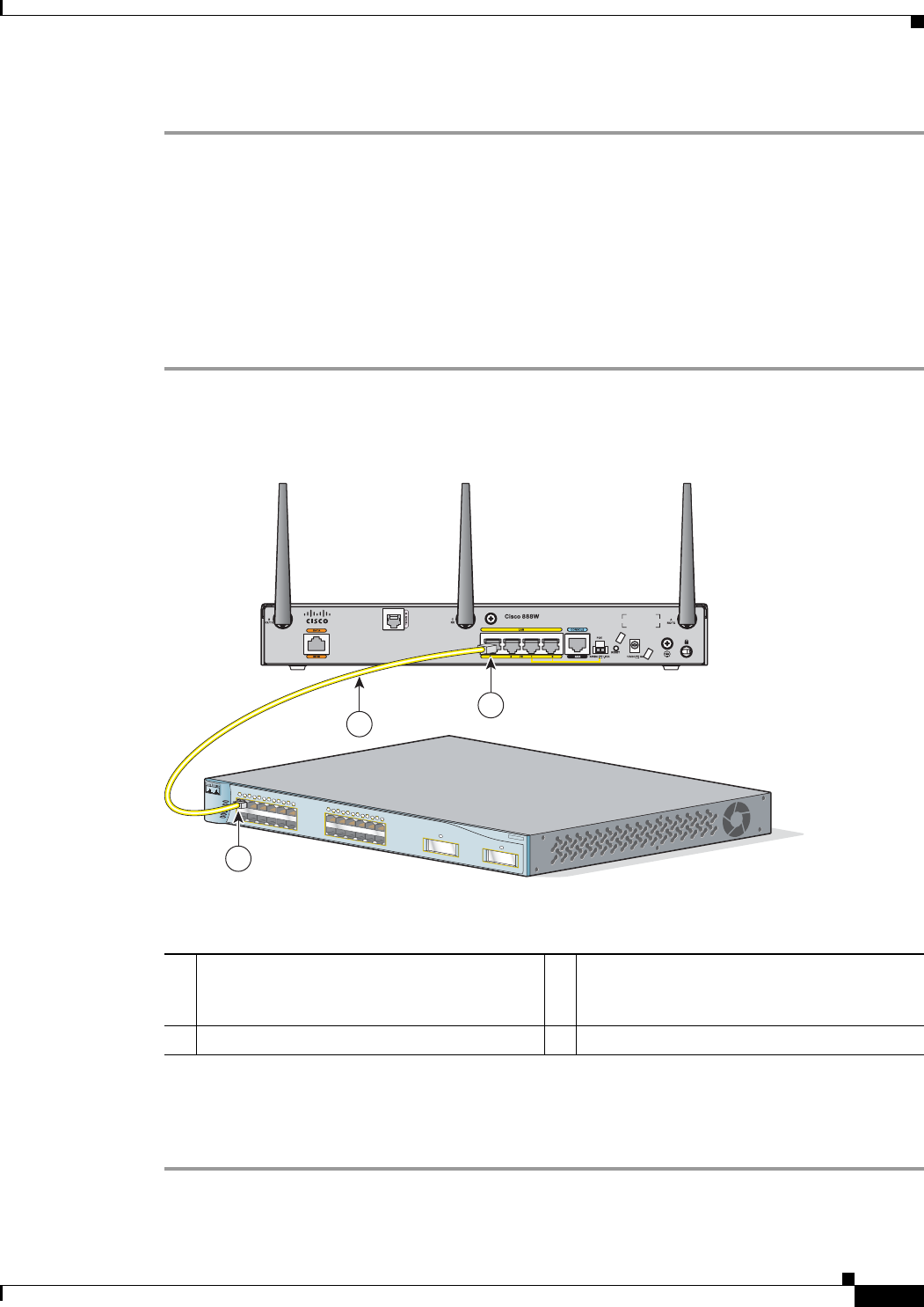
3-5
Cisco 860 Series, Cisco 880 Series, and Cisco 890 Series Integrated Services Routers Hardware Installation Guide
OL-16193-07
Chapter 3 Connecting the Router
Connecting an External Ethernet Switch
Step 2
Connect the other end of the cable to the RJ-45 port on the phone.
Connecting an External Ethernet Switch
If more than four PCs in an office must be connected to each other, you can add Ethernet connections to
the router by connecting an external Ethernet switch to the Ethernet switch on the router.
To connect an external Ethernet switch to an Ethernet switch port on the router, complete the following
steps:
Step 1
Connect one end of the yellow Ethernet cable to an Ethernet switch port on the router. Figure 3-3 shows
a Cisco 888W router connected to an Ethernet switch.
Figure 3-3 Connecting to an Ethernet Switch
Step 2
Connect the other end of the cable to the available port on the Ethernet switch to add additional Ethernet
connections.
Step 3
Turn on the Ethernet switch.
1 Ethernet switch port on the router 3Yellow CAT5 Ethernet cable,
RJ-45–to–RJ-45, connecting to an external
Ethernet switch port
2Available port on the external Ethernet switch
MODE
Catalyst 3500
SERIES
XL
INLINE POWER
SYSTEM
1X
2X
15X
16X
RPS
STATUS
UTIL
DUPLX
SPEED
12345678910 11 12
1
1X
2X
15X
16X
12345678910 11 12
2
231986
1
3
2
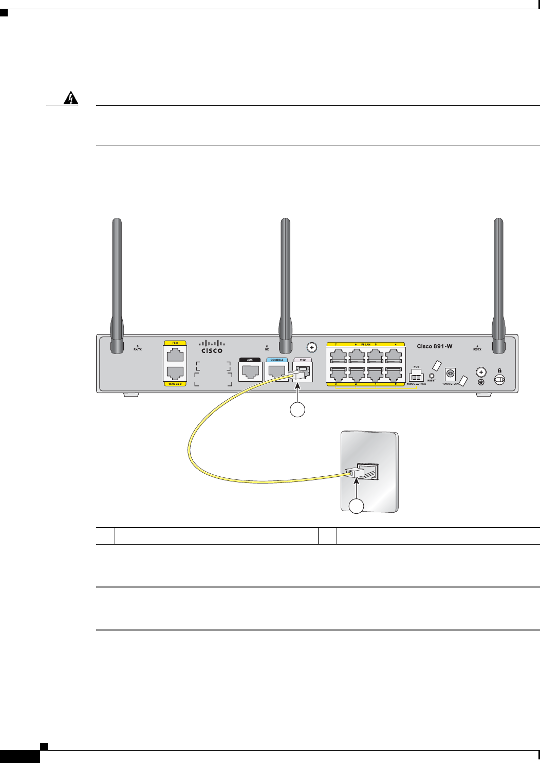
3-6
Cisco 860 Series, Cisco 880 Series, and Cisco 890 Series Integrated Services Routers Hardware Installation Guide
OL-16193-07
Chapter 3 Connecting the Router
Connecting the V.92 modem Port
Connecting the V.92 modem Port
Warning
Hazardous network voltages are present in WAN ports regardless of whether power to the unit
is OFF or ON. To avoid electric shock, use caution when working near WAN ports. When
detaching cables, detach the end away from the unit first.
Statement 1026
For dialup connection to your service provider network through the V.92 port, follow the steps given
after Figure 3-4, which show this connection.
Figure 3-4 Connecting to Your Service Provider Through the V.92 port
To connect the router to your service provide network through the V.92 port, follow these steps:
Step 1
Connect one end of the straight-through R-J11 cable to the V.92 port.
Step 2
Connect the other end of the straight through R-J11 cable to an RJ-11 telephone wall outlet.
1V.92 port on the router 2Telephone wall outlet
272387
1
2
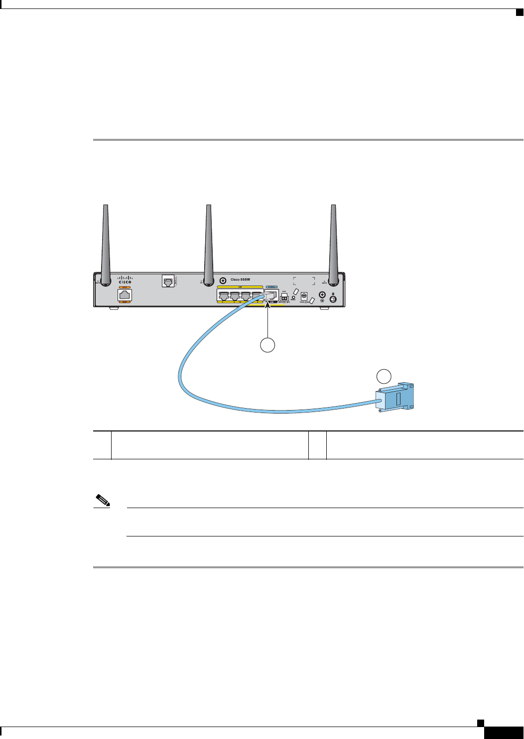
3-7
Cisco 860 Series, Cisco 880 Series, and Cisco 890 Series Integrated Services Routers Hardware Installation Guide
OL-16193-07
Chapter 3 Connecting the Router
Connecting a Terminal or PC to the Console Port
Connecting a Terminal or PC to the Console Port
Connect a terminal or PC to the Console Auxiliary (Aux) port either to configure the software by using
the CLI or to troubleshoot problems with the router.
To connect a terminal or PC to the console port on the router and access the CLI, follow these steps:
Step 1
Connect the RJ-45 end of a DB-9–to–RJ-45 serial cable to the RJ-45 Console Aux port on the router.
Figure 3-5 shows the RJ-45 end of the serial cable connected to the Console Aux port on the router.
Figure 3-5 Connecting a Terminal or PC to the Console Port
Step 2
Connect the DB-9 end of the DB-9–to–RJ-45 serial cable to the to the COM port on your laptop or PC.
Note
Some laptops and PCs do not come with DB-9 serial port connectors and may require a
USB-to-serial port adapter.
Step 3
To communicate with the router, start a terminal emulator application.
1 RJ-45 connector to the Console Aux port on
the router
2DB-9 connector
2
1
231990
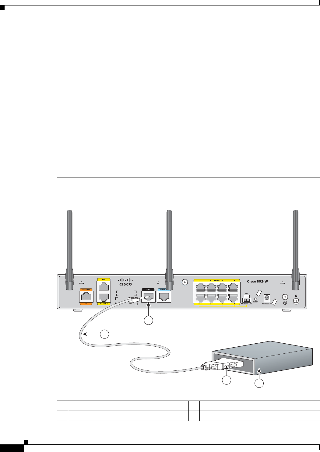
3-8
Cisco 860 Series, Cisco 880 Series, and Cisco 890 Series Integrated Services Routers Hardware Installation Guide
OL-16193-07
Chapter 3 Connecting the Router
Connecting a Modem to the Auxiliary Port
Terminal Emulator Settings
Use the following settings for the terminal emulator connection:
•
9600 baud
•
8 data bits, no parity
•
1 stop bit
•
No flow control
When the terminal emulator establishes communications, the router prompt is displayed.
For more information on terminal emulation settings, see Applying Correct Terminal Emulator Settings
for Console Connections.
Connecting a Modem to the Auxiliary Port
To connect a modem to the router, follow these steps:
Step 1
Connect the RJ-45 end of the adapter cable to the Aux port on the router as shown in Figure 3-6.
Figure 3-6 Connecting a Modem to the Aux Port
1Aux port (RJ-45) 3DB-9 to DB-25 modem adapter (if required)
2Light blue console cable 4Modem
272386
1
2
34

3-9
Cisco 860 Series, Cisco 880 Series, and Cisco 890 Series Integrated Services Routers Hardware Installation Guide
OL-16193-07
Chapter 3 Connecting the Router
Connecting the 3G Card
Step 2
Connect the DB-9 end of the console cable to the DB-9 end of the modem adapter.
Step 3
Connect the DB-25 end of the modem adapter to the modem.
Step 4
Make sure that your modem and the router auxiliary port are configured for the same transmission speed
(up to 115200 bits per second [b/s] is supported) and support mode control with data carrier detect
(DCD) and data terminal ready (DTR).
Connecting the 3G Card
Note
The Cisco 880G router does not support online insertion and removal (OIR) of the third generation
(3G)card. You must enter the shutdown command on the cellular interface before you remove the 3G
card from the router.
To connect and secure the 3G card, follow these steps:
Step 1
Align the 3G card to the 3G express card slot, as shown in Figure 3-7. Keep the card parallel to the
surface and firmly push the card into the slot.
Tip
Holding the 3G card on the flat metal surface makes it easier to align and insert the 3G card.
Note
When inserting the card into the 3G express card slot, you may hear a metal-on-metal sound as
the 3G card rubs against the internal metal cage. The 3G card is designed to fit tightly into the
3G express card slot. Firm pressure may be required to insert the card.
Note
Global System for Mobile Communications (GSM) customers need to insert a SIM card,
provided by their network carrier, into the 3G card.
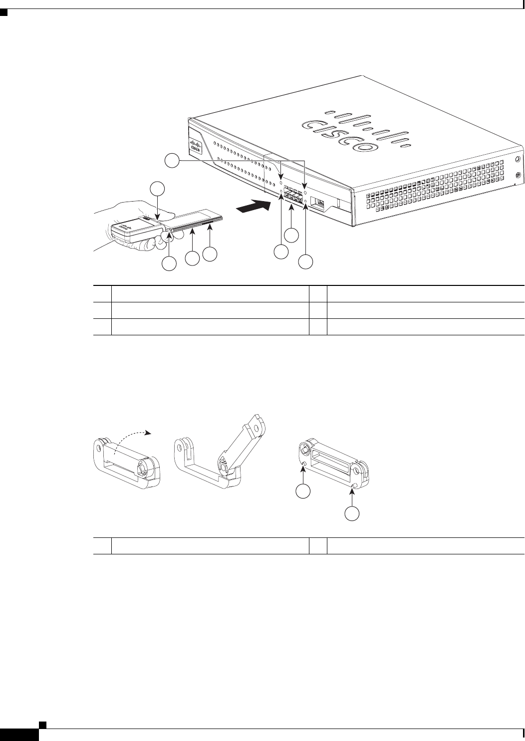
3-10
Cisco 860 Series, Cisco 880 Series, and Cisco 890 Series Integrated Services Routers Hardware Installation Guide
OL-16193-07
Chapter 3 Connecting the Router
Connecting the 3G Card
Figure 3-7 Inserting the 3G Card
Step 2
Open the top of the anti-theft locking bracket, as shown in Figure 3-8.
Figure 3-8 Opening the Anti-theft Locking Bracket
13G card with the Cisco logo facing up 4Screw holes for locking bracket
23G express card slot 5Pin holes for aligning the locking bracket
3Notches on the 3G card 6SIM slot (in HSPA
1
cards only)
1. HSPA = High-Speed Packet Access.
271473
16
2
5
4
5
3
3
1Pins on the locking bracket for alignment
271474
Front View Back View
1
1
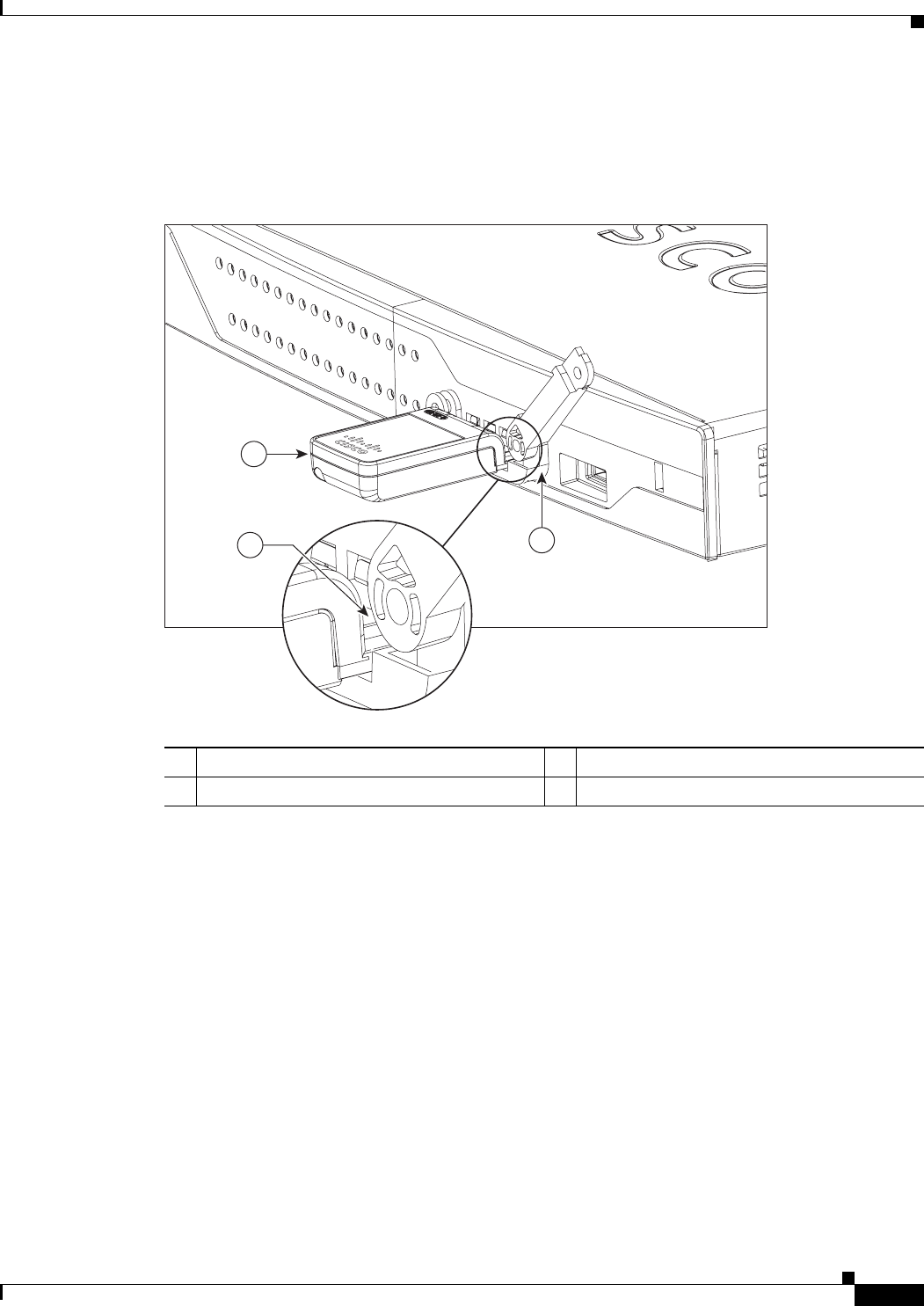
3-11
Cisco 860 Series, Cisco 880 Series, and Cisco 890 Series Integrated Services Routers Hardware Installation Guide
OL-16193-07
Chapter 3 Connecting the Router
Connecting the 3G Card
Step 3
Slide the opened locking bracket under the 3G card. The locking bracket should align with the notches
on either side of the 3G card, as shown in Figure 3-9, and the pins on the locking bracket should be
inserted into the corresponding holes in the router.
Figure 3-9 Installing the Locking Bracket
13G card 3Notch on the 3G card
2Locking bracket
1
2
3
271726
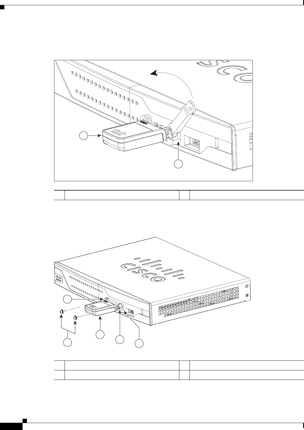
3-12
Cisco 860 Series, Cisco 880 Series, and Cisco 890 Series Integrated Services Routers Hardware Installation Guide
OL-16193-07
Chapter 3 Connecting the Router
Connecting the 3G Card
Step 4
Close the locking bracket, as shown in Figure 3-10.
Figure 3-10 Closing the Locking Bracket
Step 5
Insert the screws, as shown in Figure 3-11, and tighten with a number 2 Phillips screwdriver.
Figure 3-11 Inserting the Screws
Step 6
To connect the antenna to the 3G card, insert the antenna connector into the antenna connector receptacle
on the 3G card.
13G card 2Locking bracket
1
2
271580
13G card 3Screws
2Locking bracket 4Screw holes on the locking bracket
271476
342
1
4
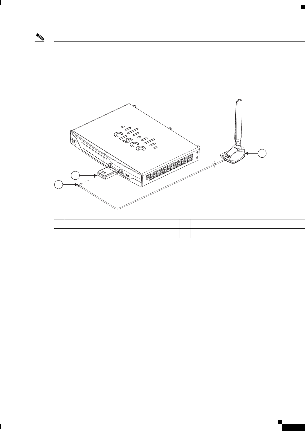
3-13
Cisco 860 Series, Cisco 880 Series, and Cisco 890 Series Integrated Services Routers Hardware Installation Guide
OL-16193-07
Chapter 3 Connecting the Router
Connecting the 3G Card
Note
The antenna connector receptacle may be located on the left, right, or front of the 3G card, depending
on your card.
Figure 3-12 shows the antenna connected to the 3G card with an SSMB type plug, and Figure 3-13 shows
the antenna with the SMK-TS-9 connector.
Figure 3-12 Antenna connected to the 3G Card with SSMB connector
1Antenna on a cradle 3Antenna connector receptacle
1
1. The antenna connector receptacle is located on either the left, right or front of the card for different SKUs. Please locate the
receptacle of your card before plugging in the cable.
2Antenna SSMB connector
272653
1
2
3
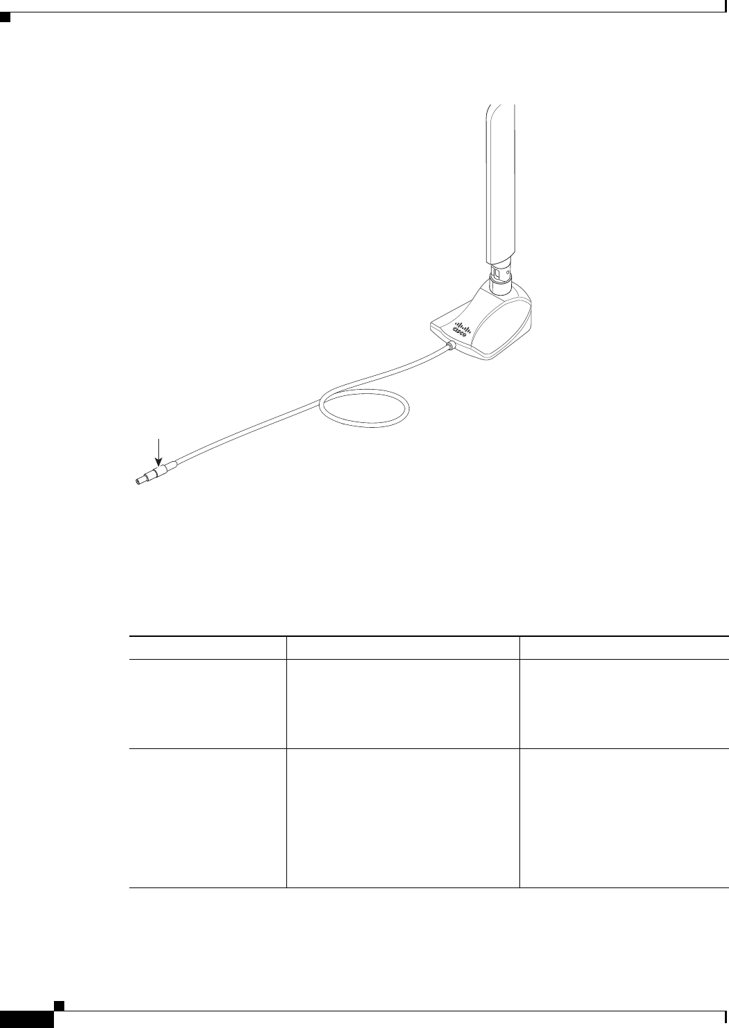
3-14
Cisco 860 Series, Cisco 880 Series, and Cisco 890 Series Integrated Services Routers Hardware Installation Guide
OL-16193-07
Chapter 3 Connecting the Router
Connecting the 3G Card
Figure 3-13 Antenna with the SMK-TS- 9 Connector
If you are using an extension cable, you must attach the 3G adapter for extended cable antenna to the
body of the router. Depending on the SKU ordered, the adapters come with different connectors.
Table 3-1 lists the different adapters and SKUs supported by each adapter. For instructions on how to
install the adapter, see the “Installing the 3G Adapter for Extended Cable/Antenna” section on
page 3-15. Otherwise, follow Step 7.
Step 7
Clean the flat surface to which you will affix the antenna.
279085
Original
antenna assembly
SMK-TS-9
connector Cable
Tabl e 3-1 3G Adapters and Supported SKUs
3G Adapter SKU Description SKUs Supported
3G-ACC-SMKTS9-TNC 3G adapter for extended cable/antenna
with an SMK-TS-9 to TNC connector.
Use this with the pentaband dipole
indoor antenna
(3G-ANTM-SMKTS9).
PCEX-3G-HSPA-R6,
CISCO881G-G-K9
3G-ACC-SSMB-TNC 3G adapter for extended cable/antenna
with an SSMB to TNC connector. Use
this with the pentaband dipole indoor
antenna shipped with your product.
PCEX-3G-HSPA,
PCEX-3G-HSPA-A,
PCEX-3G-CDMA-S,
PCEX-3G-CDMA-V,
PCEX-3G-CDMA-B,
CISCO881G-A-K9,
CISCO881G-S-K9,
CISCO881G-V-K9
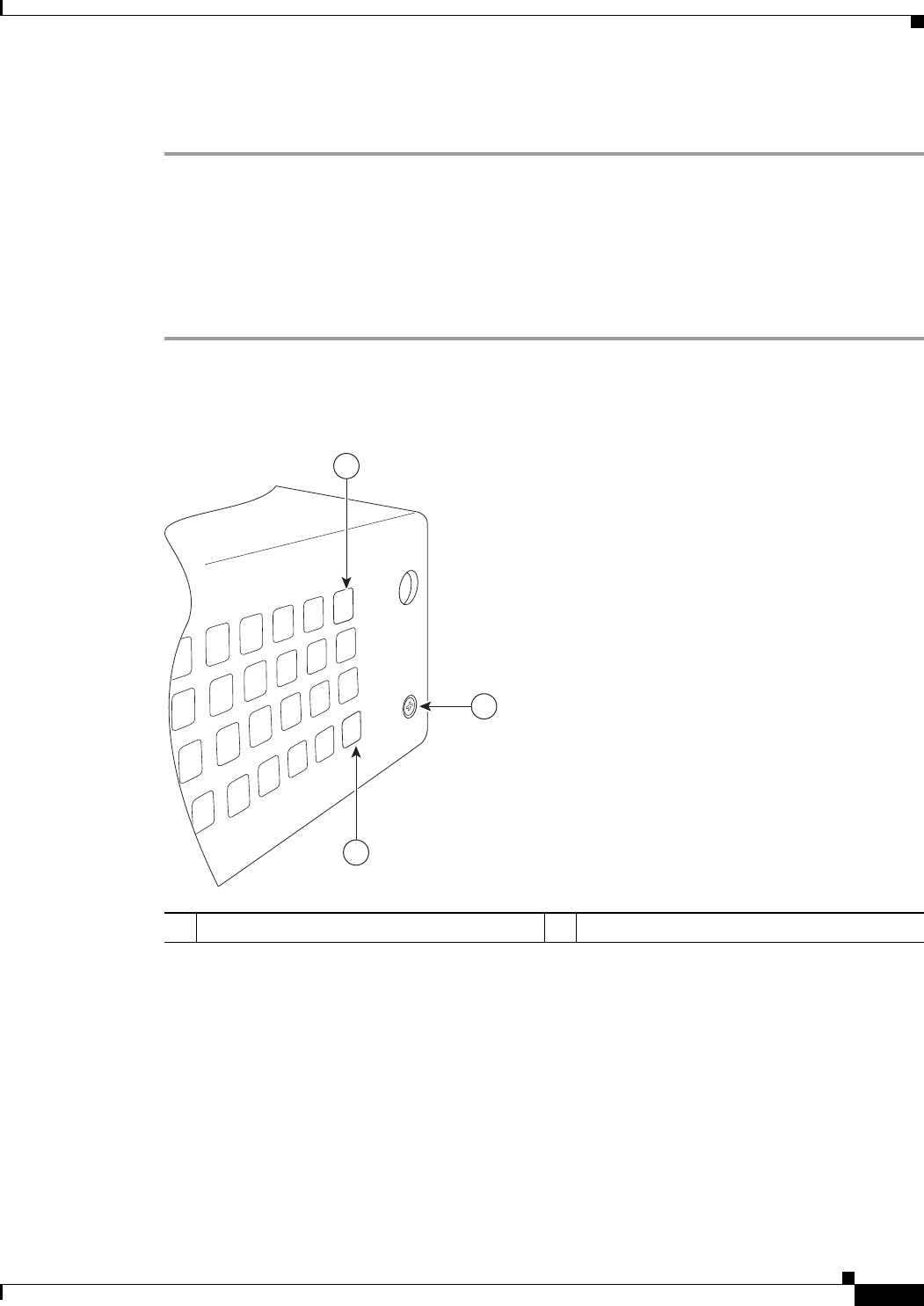
3-15
Cisco 860 Series, Cisco 880 Series, and Cisco 890 Series Integrated Services Routers Hardware Installation Guide
OL-16193-07
Chapter 3 Connecting the Router
Installing the 3G Adapter for Extended Cable/Antenna
Step 8
Remove the protective tape from the adhesive on the bottom of the antenna cradle, then firmly press the
cradle to the flat surface.
Installing the 3G Adapter for Extended Cable/Antenna
For better signal and reception, if you are using the Cisco 3G Adapter for Extended Cable/Antenna,
3G-ACC-SMKTS9-TNC, follow these steps to install it:
Step 1
Locate and remove the Phillips screw on the left side of the router as shown in Figure 3-14. Keep the
screw aside for Step 4.
Figure 3-14 Locating the Phillips Screw
1Phillips screw on the left side of router 2Air vent holes to be aligned with adapter
279124
2
2
1
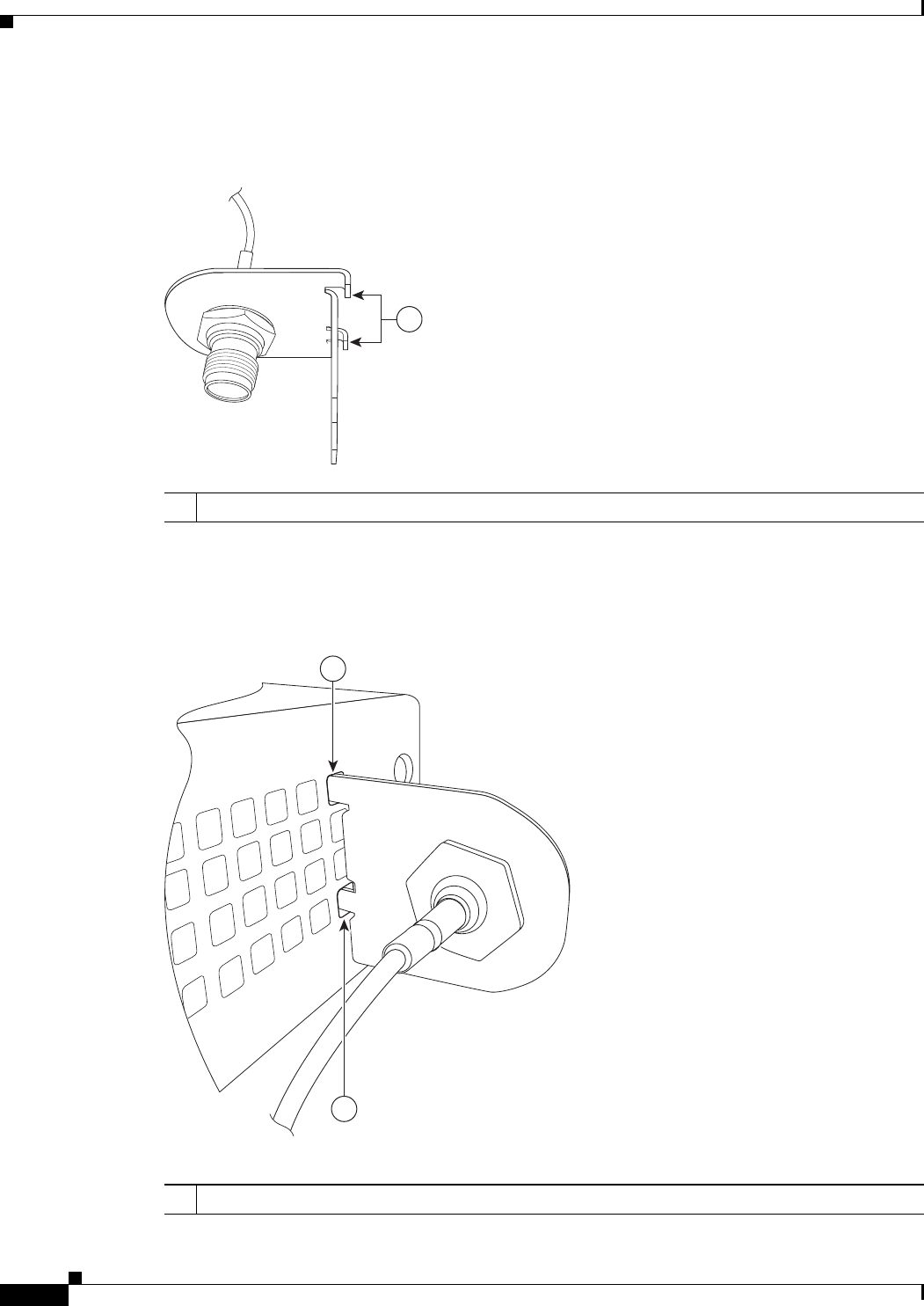
3-16
Cisco 860 Series, Cisco 880 Series, and Cisco 890 Series Integrated Services Routers Hardware Installation Guide
OL-16193-07
Chapter 3 Connecting the Router
Installing the 3G Adapter for Extended Cable/Antenna
Step 2
Locate the hooks on the adapter as shown in Figure 3-15.
Figure 3-15 Locating the Hooks on the Adapter
Step 3
Align and insert the hooks of the adapter into the air vent holes on the left side router body as shown in
Figure 3-16.
Figure 3-16 Inserting the Hooks
279122
1
1Hooks on the adapter
279123
1
1
1Hooks aligned and inserted into the router.

3-17
Cisco 860 Series, Cisco 880 Series, and Cisco 890 Series Integrated Services Routers Hardware Installation Guide
OL-16193-07
Chapter 3 Connecting the Router
Installing the 3G Adapter for Extended Cable/Antenna
Step 4
Align the circular adapter hole with the hole on the router chassis from where you removed the screw in
Step 1 and use the screw to attach the adapter to the router as shown in Figure 3-17.
Figure 3-17 Attaching the Adapter
279091
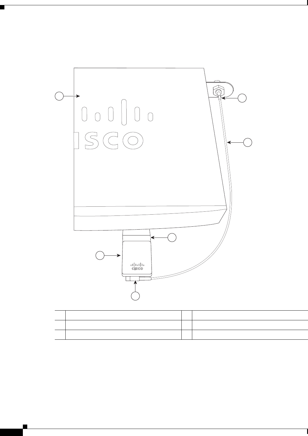
3-18
Cisco 860 Series, Cisco 880 Series, and Cisco 890 Series Integrated Services Routers Hardware Installation Guide
OL-16193-07
Chapter 3 Connecting the Router
Installing the 3G Adapter for Extended Cable/Antenna
Step 5
Connect the extension cable to the 3G card as described in the “Connecting the 3G Card” section on
page 3-9. The complete assembly is shown in Figure 3-18.
Figure 3-18 Adapter Connected to 3G Card and Router Chassis
Now the adapter is ready for use with the extension cable. Table 3-2 lists the loss information for the
ultra-low-loss (ULL) LMR 400 cables available with the adpater for the 3G fixed platforms.
1Router chassis 4SSMB or SMK-TS-9 connector
23G adapter for extended cable/antenna 53G card inserted into the router
3Cable 63G card
279089
3
2
1
6
5
4

3-19
Cisco 860 Series, Cisco 880 Series, and Cisco 890 Series Integrated Services Routers Hardware Installation Guide
OL-16193-07
Chapter 3 Connecting the Router
Connecting a Data BRI Port
For additional information on all the available cables and antennas available for 3G, go to:
http://www.cisco.com/en/US/docs/routers/access/1800/1861/software/feature/guide/mrwlsgsm.html#w
p1262730
Connecting a Data BRI Port
You can connect the Data BRI port to the ISDN service provider as a backup link to the WAN port in
case the primary xDSL (general term referring to various forms of DSL, including global industry
standard symmetrical high-speed DSL [G.SHDSL]) WAN service fails. The Data BRI connection is not
available on the third-generation (3G) models.
The cabling requirements for the ISDN S/T connection are as follows:
•
You must provide two unshielded Category 5 cables. The first cable connects the NT1 box to the
splitter, and the second cable connects the splitter to the wall jack.
•
There are RJ-45 connectors at both ends of the default orange ISDN S/T cable. However, an
RJ-45–to–RJ-11 ISDN S/T cable is available upon request if the wall jack at the site requires an
RJ-11 connector. Contact your router reseller for the appropriate cable.
Caution
Both LAN and WAN ports use RJ-45 connectors. Use caution when connecting cables to these
connectors. To avoid damage to the router, do not connect telephone-network voltage (TNV) circuits
(such as ISDN or DSL circuits) to safety extra-low voltage (SELV) circuits (such as LAN circuits).
Tabl e 3-2 Cisco Adapter Cables for Use with 3G Fixed Routers
Cisco Product Number
Antenna Adapter
Length Insertion Loss Frequency (MHz)
3G-ACC-SSMB-TNC 14.5 inches 0.66 dB 2100
3G-ACC-TS9-TNC 13.5 inches 0.62 dB 2100
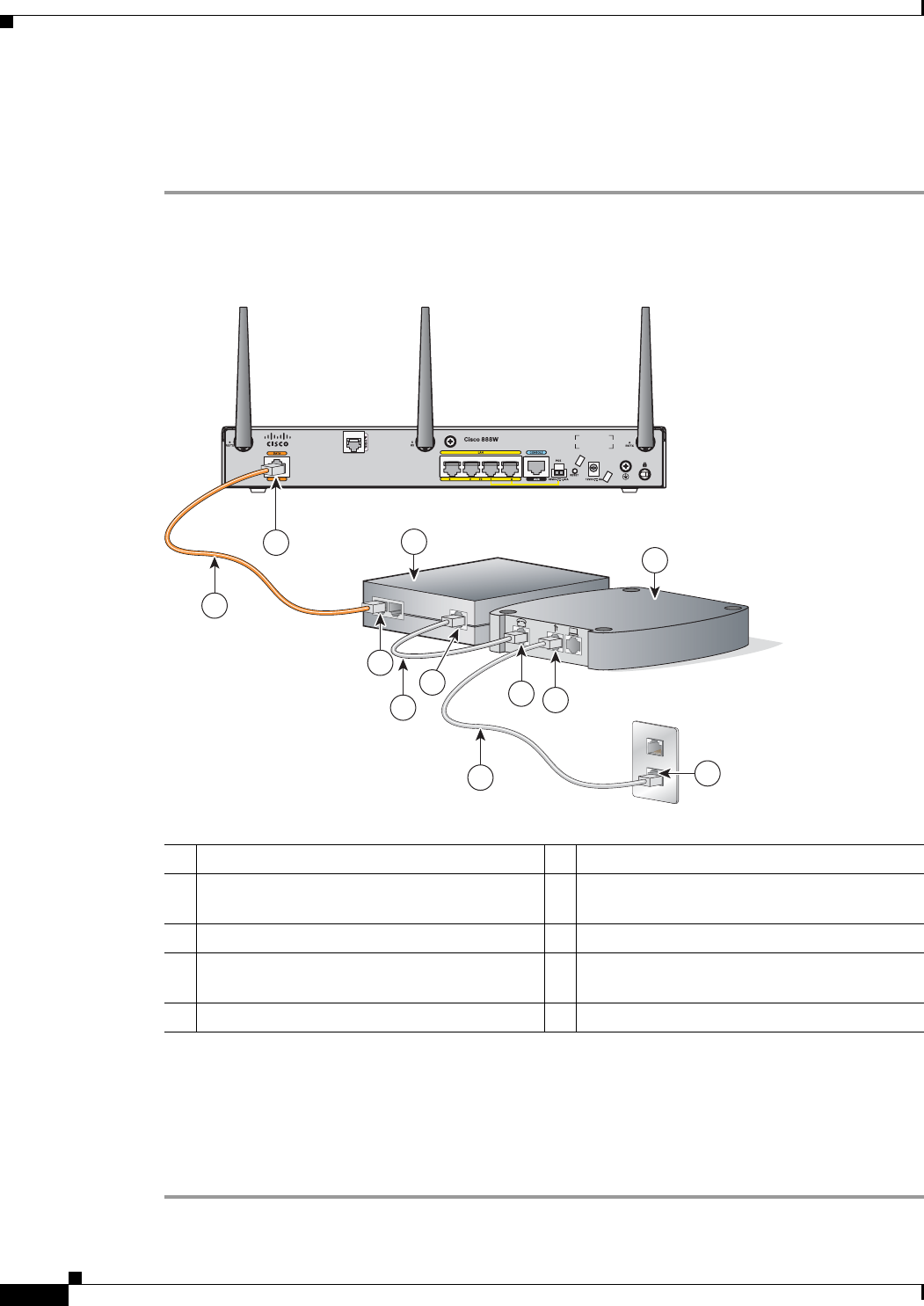
3-20
Cisco 860 Series, Cisco 880 Series, and Cisco 890 Series Integrated Services Routers Hardware Installation Guide
OL-16193-07
Chapter 3 Connecting the Router
Connecting a Data BRI Port
Although the following procedure shows a Cisco 888W data router, this procedure applies to all
Cisco 880 series router with a Data BRI port.
To connect the Data BRI port to the ISDN service provider, follow these steps:
Step 1
Connect one end of the orange ISDN S/T cable to the Data BRI port on the router. Figure 3-19 shows a
Data BRI connection.
Figure 3-19 Connecting the Data BRI Port to the ISDN Line
Step 2
Connect the other end of the orange ISDN S/T cable to the S/T port on the NT1 box.
Step 3
Connect the first unshielded CAT 5 cable from the U-port on the NT1 box to the telephone line port on
the splitter.
Step 4
Connect the second unshielded Category 5 cable from the telecommunication service port on the splitter
to the wall jack to allow a link to the network service provider.
1Data BRI port on the router 6U-port on the NT1 box
2ISDN S/T cable 7xDSL splitter (provided by the xDSL service
provider)
3Network termination 1 (NT1) box 8Telephone line port on the splitter
4S/T port on the NT1 box 9Telecommunication service port on the
splitter
5Unshielded CAT 5 cable 10 Wall jack
231991
3
1
4
2
10
6
9
8
7
5
5
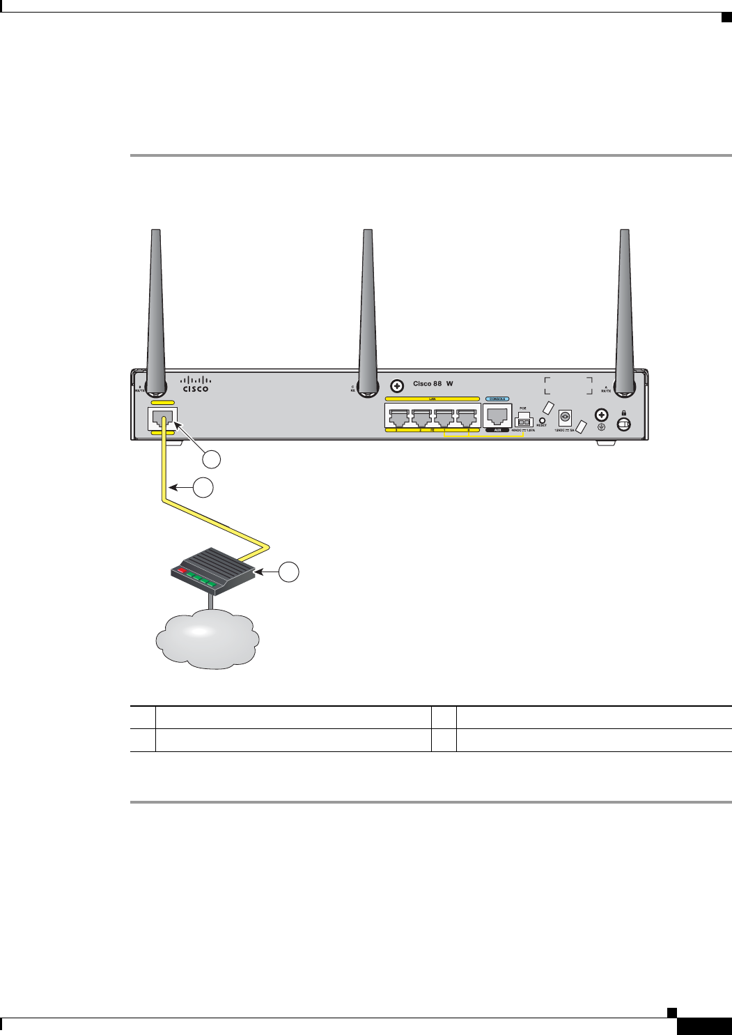
3-21
Cisco 860 Series, Cisco 880 Series, and Cisco 890 Series Integrated Services Routers Hardware Installation Guide
OL-16193-07
Chapter 3 Connecting the Router
Connecting an FE Line to an FE WAN Port
Connecting an FE Line to an FE WAN Port
To connect the Fast Ethernet (FE) WAN port on the router, follow these steps:
Step 1
Connect one end of the yellow cable to the FE WAN port as shown in Figure 3-20.
Figure 3-20 Connecting the FE WAN Port
Step 2
Connect the other end of cable to an available port on the modem.
1FE WAN port 3Modem connected to the Internet
2CAT 5 cable
WAN
FE 4
1
Internet
Internet
Internet
2
3
231992
1
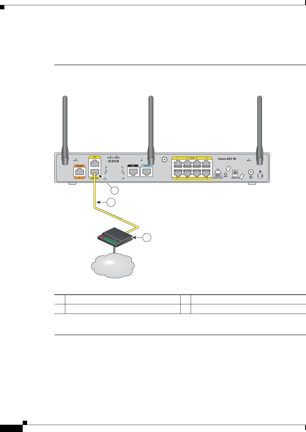
3-22
Cisco 860 Series, Cisco 880 Series, and Cisco 890 Series Integrated Services Routers Hardware Installation Guide
OL-16193-07
Chapter 3 Connecting the Router
Connecting an GE Line to an GE WAN Port
Connecting an GE Line to an GE WAN Port
To connect the Gigabit Ethernet (GE) WAN port on the router, follow these steps:
Step 1
Connect one end of the yellow cable to the GE WAN port as shown in Figure 3-21.
Figure 3-21 Connecting the GE WAN Port
Step 2
Connect the other end of cable to an available port on the modem.
1GE WAN port 3Modem connected to the Internet
2CAT 5 cable
Internet
Internet
Internet
2
3
274493
1
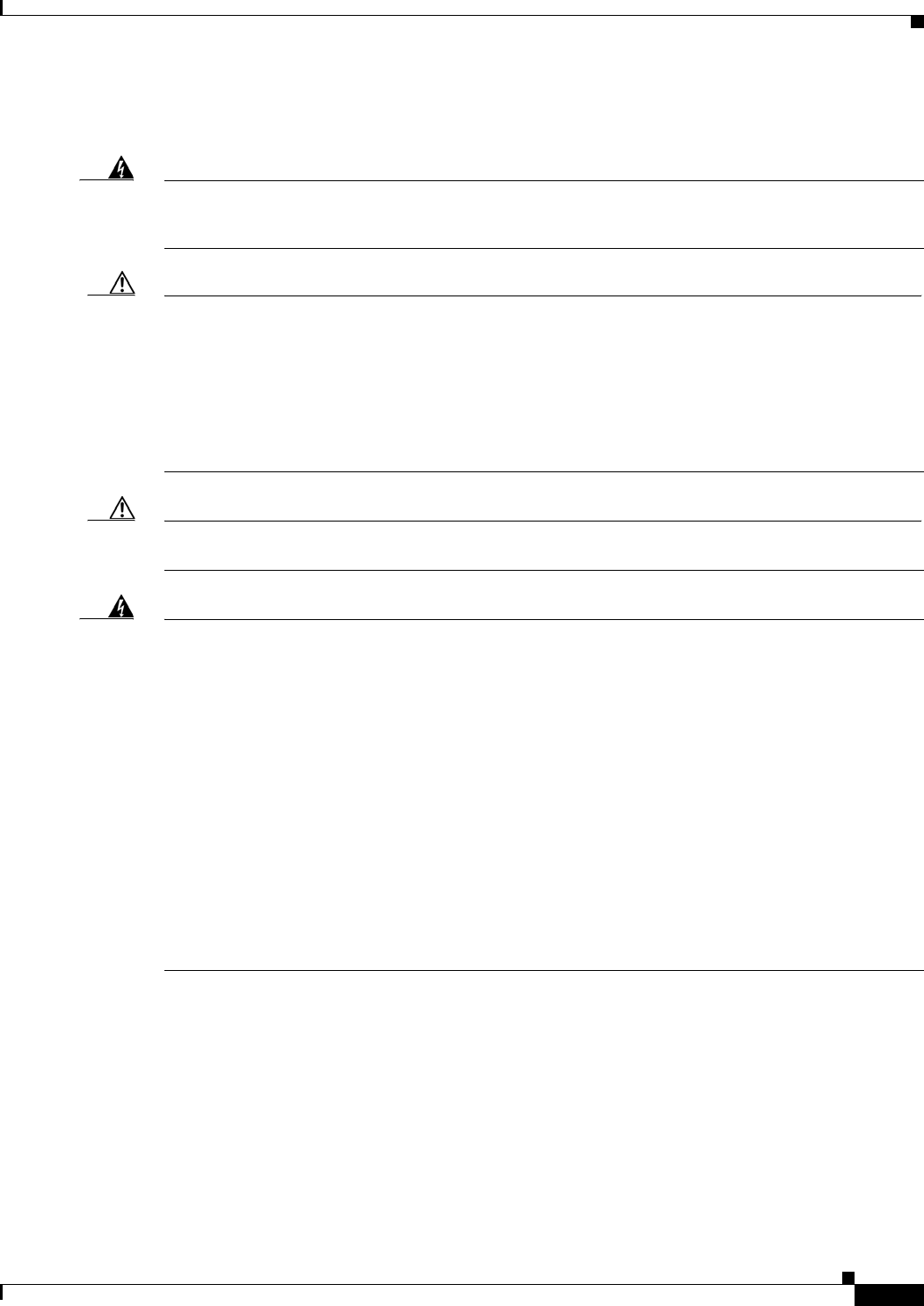
3-23
Cisco 860 Series, Cisco 880 Series, and Cisco 890 Series Integrated Services Routers Hardware Installation Guide
OL-16193-07
Chapter 3 Connecting the Router
Connecting an xDSL Line
Connecting an xDSL Line
Warning
Hazardous network voltages are present in WAN ports regardless of whether power to the unit
is OFF or ON. To avoid electric shock, use caution when working near WAN ports. When
detaching cables, detach the end away from the unit first.
Statement 1026
Caution
Cisco Systems DSL WAN Interfaces are tested for compliance with regulatory standards such as FCC
Part 68, ITU-T K.21, IEC 61000-4-5, and CSA/EN/IEC/UL 60950-1. These standards assume Primary
Protection devices protect the Customer Premise Equipment (CPE). These devices are normally
installed by the service provider, local exchange carrier or qualified service person and are located at the
telecom service provider entrance, network interface box, or demarcation point. See Figure 3-22 for the
likely location of the primary protection device. The primary protection device must be suitable for the
xDSL interface employed. Please contact your sales team or qualified service person for further
information and installation.
Caution
To reduce the risk of fire, use only No. 26 AWG or larger (e.g., 24 AWG) UL Listed or CSA Certified
Telecommunication Line Cord.
Warning
IMPORTANT SAFETY INSTRUCTIONS
When using your telephone equipment, basic safety precautions should always be followed to
reduce the risk of fire, electric shock and injury to persons, including the following:
- Do not use this product near water - for example, near a bathtub, washbowl, kitchen sink or
laundry tub, in a wet basement or near a swimming pool.
- Avoid using a telephone (other than a cordless type) during an electrical storm. There may be
a remote risk of electric shock from lightning.
- Do not use the telephone to report a gas leak in the vicinity of the leak.
- Use only the power cord and batteries indicated in this manual. Do not dispose of batteries in a
fire. They may explode. Check with local codes for possible special disposal instructions.
SAVE THESE INSTRUCTIONS
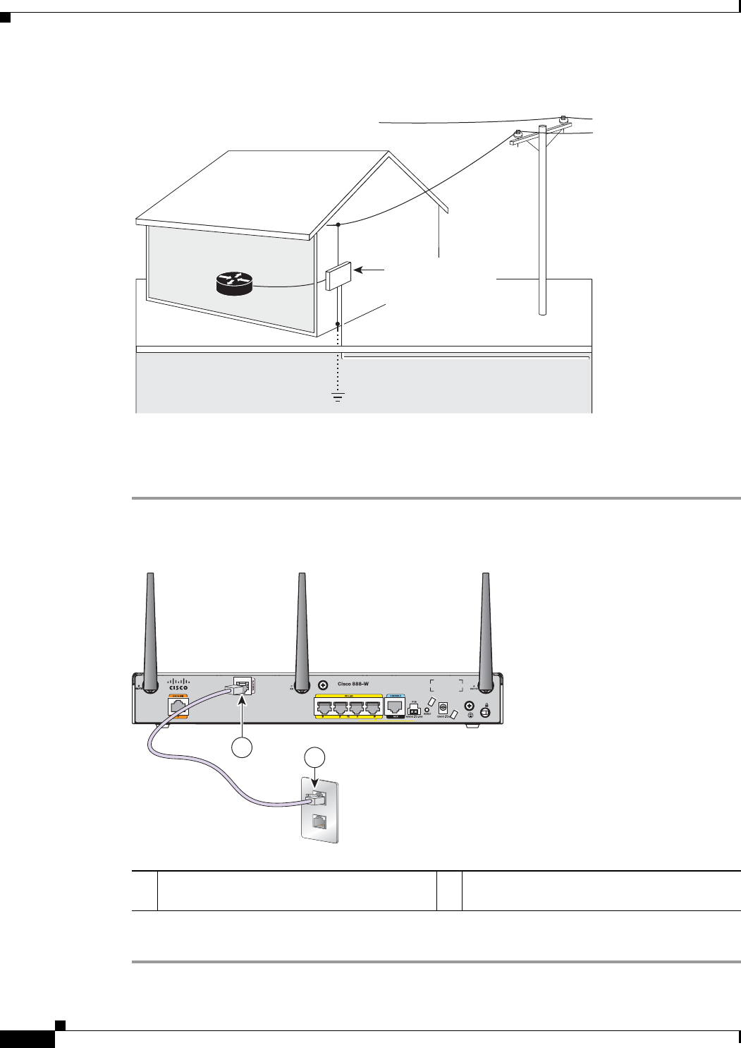
3-24
Cisco 860 Series, Cisco 880 Series, and Cisco 890 Series Integrated Services Routers Hardware Installation Guide
OL-16193-07
Chapter 3 Connecting the Router
Connecting an xDSL Line
Figure 3-22 Primary Protection Device Location
To connect the router to a global industry standard symmetrical high-speed DSL (G.SHDSL) line,
very-high-speed digital subscriber line 2 (VDSL2) port, or an ADSL2+ line, follow these steps:
Step 1
Connect one end of an RJ-11 (RJ-45 on 880 E models) cable to the port on the router. See Figure 3-23.
Figure 3-23 Connecting the xDSL Line
Step 2
Connect the other end of the cable to the DSL wall jack.
Router
Home or Business
Service Utilities Entrance
or Demarcation Point
Network Interface Box/
Network Interface Device/
Station Protector
Building Ground Rod connected to
Service entrance and Primary Protection
* Alternative Underground Service Entrance
Note: Primary Protection
may be located Outside
or Inside of Premise
Telecom Service
Overhead Service
Entrance
281392
1G.SHDSL port, VDSL2oPOTs port, or
ADSL2+ port
2DSL wall jack
2
32175
2
1

3-25
Cisco 860 Series, Cisco 880 Series, and Cisco 890 Series Integrated Services Routers Hardware Installation Guide
OL-16193-07
Chapter 3 Connecting the Router
Connecting Power over Ethernet
Caution
The primary WAN port is designed for an RJ-45 connector only. Damage to the primary WAN port may
occur if a non RJ-45 connector is inserted
Note
The DSL line must be provisioned by your service provider and correctly configured so that the LED
shows the carrier detect (CD) status. On Cisco 860VAE routers, check the DSL Link LED.
Connecting Power over Ethernet
Warning
This unit might have more than one power supply connection. All connections must be removed
to de-energize the unit.
Statement 1028
Warning
This product must be connected to a power-over-ethernet (PoE) IEEE 802.3af compliant power
source or an IEC60950 compliant limited power source.
Statement 353
Figure 3-24 shows how to connect the 48-VDC Power over Ethernet (PoE) power adapter to your router.
The PoE adapter provides power to ports 0 and 1 of the 4-port 10/100 FE switch on the Cisco 880 series
routers and ports 0,1, 2, and 3 of the 8-port 10/100 FE switch on the Cisco 890 series routers.
Note
The router must also be connected to an AC power outlet through a 12-VDC adapter. To connect the
router to an AC outlet, see “Connecting the AC Adapter” section on page 3-26.
Note
Be sure that the internal PoE is enabled for this connection procedure to work.
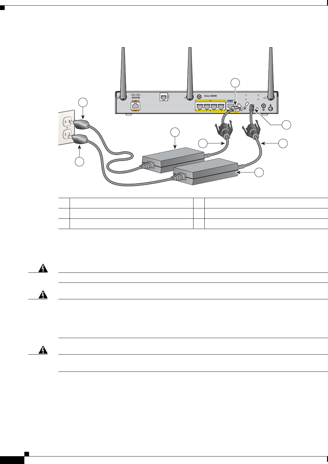
3-26
Cisco 860 Series, Cisco 880 Series, and Cisco 890 Series Integrated Services Routers Hardware Installation Guide
OL-16193-07
Chapter 3 Connecting the Router
Connecting the AC Adapter
Figure 3-24 Connecting PoE
Connecting the AC Adapter
Warning
The device is designed to work with TN power systems.
Statement 19
Warning
This product relies on the building’s installation for short-circuit (overcurrent) protection.
Ensure that a fuse or circuit breaker no larger than 120VAC, 20A U.S. (240VAC, 16 to 20A
international) is used on the phase conductors (all current-carrying conductors). The fuse or
circuit breaker must have adequate safety approvals recognized by the country of usage.
Statement 119
Warning
This unit might have more than one power supply connection. All connections must be removed
to de-energize the unit.
Statement 1028
148-VDC PoE input jack 4AC plug
2Power cord 512-VDC input power-jack plug
3Power adapter—48 VDC 6Power adapter—12 VDC
231995
5
22
6
4
4
3
1
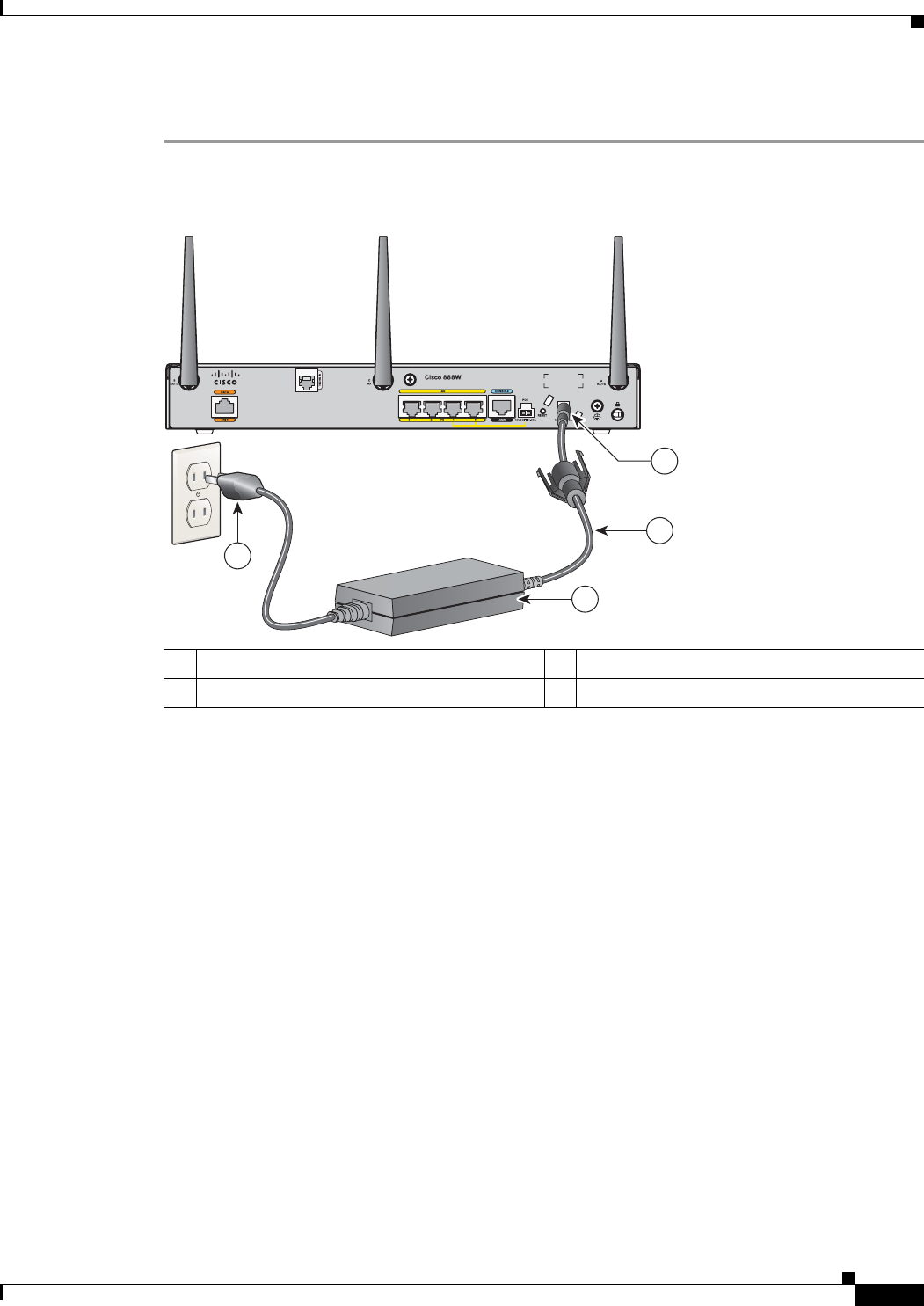
3-27
Cisco 860 Series, Cisco 880 Series, and Cisco 890 Series Integrated Services Routers Hardware Installation Guide
OL-16193-07
Chapter 3 Connecting the Router
Connecting the AC Adapter
To connect your Cisco 860 series or Cisco 880 series ISR to an AC power outlet, follow these steps:
Step 1
Connect the router to an AC power outlet as shown in Figure 3-25.
Figure 3-25 Connecting the AC Adapter
112-VDC plug 3Power adapter—12 VDC
2Power cord 4AC plug
231996
1
2
4
3
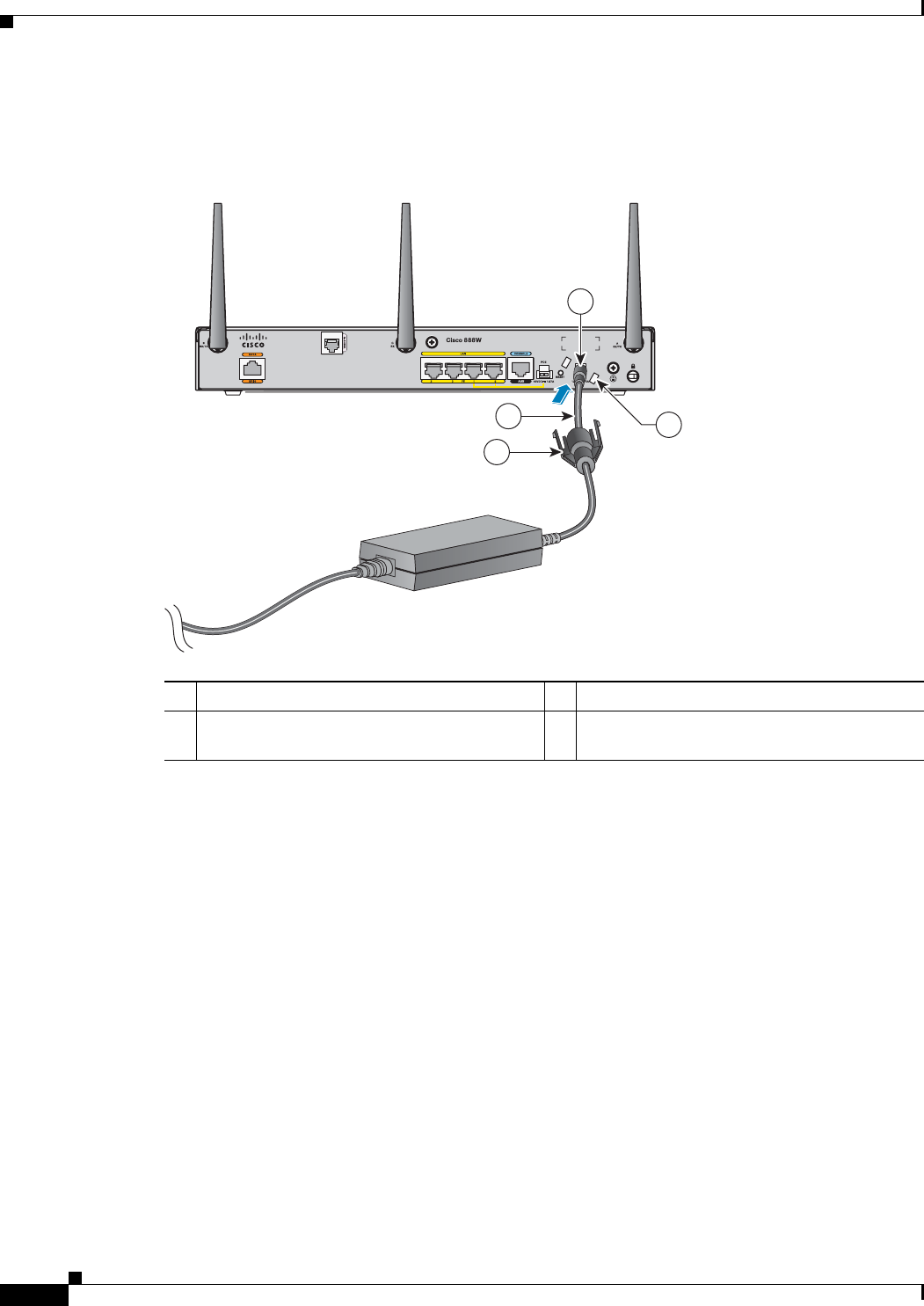
3-28
Cisco 860 Series, Cisco 880 Series, and Cisco 890 Series Integrated Services Routers Hardware Installation Guide
OL-16193-07
Chapter 3 Connecting the Router
Connecting the AC Adapter
Step 2
To secure the power cord to the router, attach the power lock clip to the power cord, slide the clip to the
end of the DC plug, and secure the retaining clip into the router chassis. See Figure 3-26.
Figure 3-26 Securing the Power Cord
1Power lock clip 3DC plug
2Power cord 4Lock holes on either side of the power
connector
270659
4
2
1
3
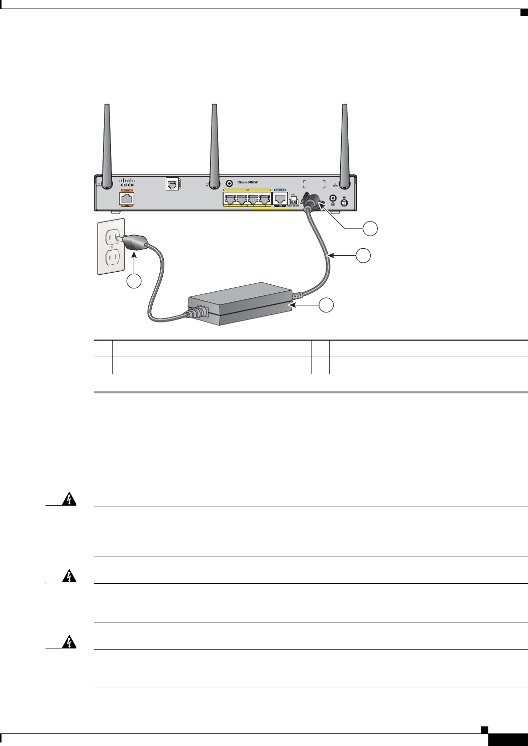
3-29
Cisco 860 Series, Cisco 880 Series, and Cisco 890 Series Integrated Services Routers Hardware Installation Guide
OL-16193-07
Chapter 3 Connecting the Router
Connecting an FXS Line
Step 3
Snap the latches into the holes on either side of the power connector. See Figure 3-27.
Figure 3-27 Power Lock Clip Latched Into the Holes on Either Side of the Power Connector
Connecting an FXS Line
Use a standard straight-through RJ-11 modular telephone cable to connect a Foreign Exchange Service
(FXS) port to a telephone or fax machine.
Warning
This equipment contains a ring signal generator (ringer), which is a source of hazardous voltage.
Do not touch the RJ-11 (phone) port wires (conductors), the conductors of a cable connected to
the RJ-11 port, or the associated circuit-board when the ringer is active. The ringer is activated
by an incoming call.
Warning
Hazardous network voltages are present in WAN ports regardless of whether power to the unit
is OFF or ON. To avoid electric shock, use caution when working near WAN ports. When
detaching cables, detach the end away from the unit first.
Statement 1026
Warning
For connections outside the building where the equipment is installed, the following ports must
be connected through an approved network termination unit with integral circuit protection:
FXS.
1Power lock clip 3Power adapter
2Power cord 4AC plug
270800
1
2
4
3
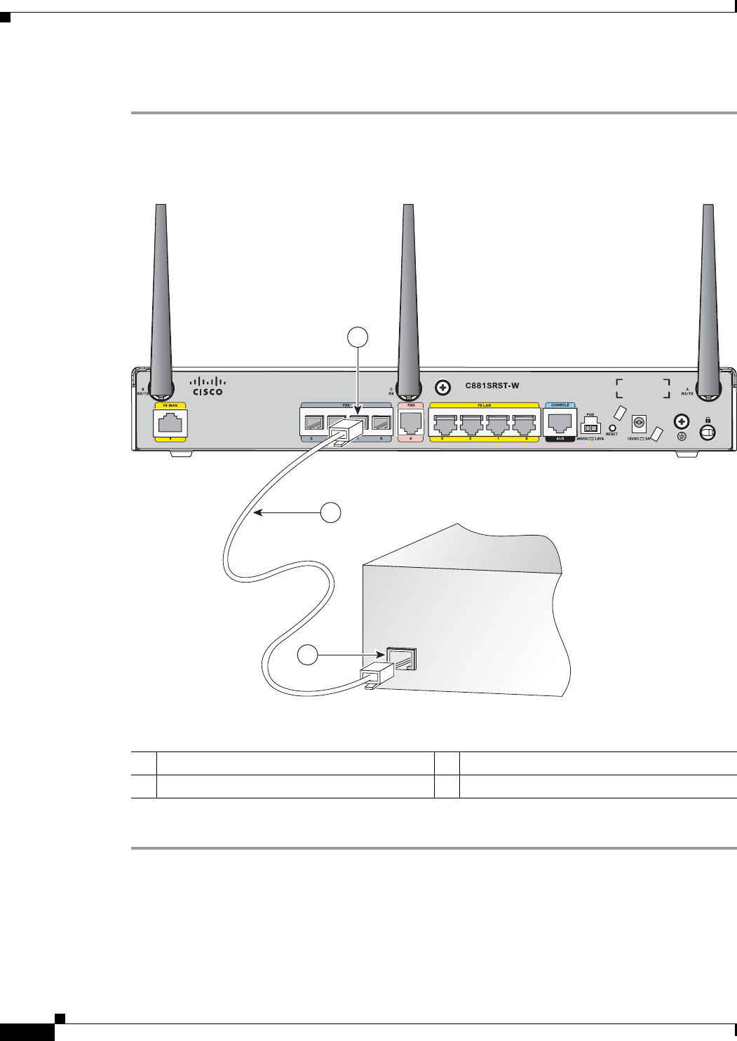
3-30
Cisco 860 Series, Cisco 880 Series, and Cisco 890 Series Integrated Services Routers Hardware Installation Guide
OL-16193-07
Chapter 3 Connecting the Router
Connecting an FXS Line
To connect the FXS line, follow these steps:
Step 1
Connect one end of the straight-through RJ-11 cable to the FXS port. Figure 3-28 shows an FXS line
connection.
Figure 3-28 Connecting an FXS Line
Step 2
Connect the other end of the cable to the RJ-11 port on the fax machine or telephone.
1FXS port 3RJ-11 port
2RJ-11 cable
Fax machine
or telephone
241907
1
2
3
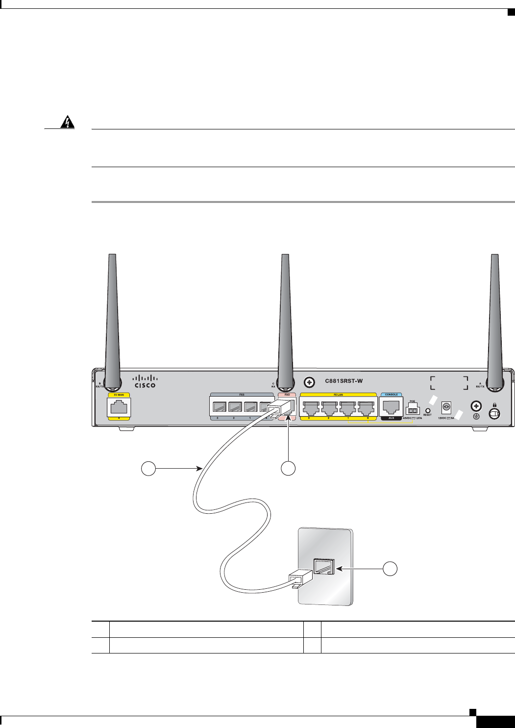
3-31
Cisco 860 Series, Cisco 880 Series, and Cisco 890 Series Integrated Services Routers Hardware Installation Guide
OL-16193-07
Chapter 3 Connecting the Router
Connecting an FXO Line
Connecting an FXO Line
Use a straight-through RJ-11 cable to connect the FXO voice port to the PSTN or PBX through a
telephone wall outlet.
Warning
Hazardous network voltages are present in WAN ports regardless of whether power to the unit
is OFF or ON. To avoid electric shock, use caution when working near WAN ports. When
detaching cables, detach the end away from the unit first.
Statement 1026
To connect the FXO line, follow these steps:
Step 1
Connect one end of the straight-through RJ-11 cable to the FXO port. See Figure 3-29.
Figure 3-29 Connecting an FXO Line
Step 2
Connect the other end of the RJ-11 cable to a telephone wall outlet.
1FXO port 3Telephone outlet
2RJ-11 cable
270542
21
3
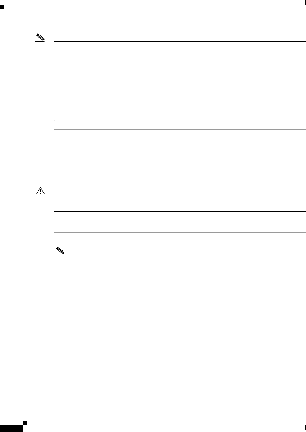
3-32
Cisco 860 Series, Cisco 880 Series, and Cisco 890 Series Integrated Services Routers Hardware Installation Guide
OL-16193-07
Chapter 3 Connecting the Router
Connecting a Voice ISDN BRI Line
Note
If you have specified the use of a private line automatic ringdown (PLAR) off-premises extension (OPX)
connection mode for an FXO voice port (with loop resistance less than 8000 Ohm), you must ensure that
the soft-offhook option is enabled on the port.
This option allows a stepped offhook resistance during seizure, which avoids overloading the circuit
during offhook in the event that ringing voltage is present on the circuit at the same time as the trunk
seizure. The stepped offhook resistance is initially set to 800 Ohms, then adjusts to 50 Ohms when
ringing voltage is not present.
To enable the soft-offhook command on the port, and to access the connection command with plar opx
syntax, see the Cisco Command Lookup Tool.
Connecting a Voice ISDN BRI Line
Use a straight-through RJ-45 cable to connect the voice BRI port to the ISDN network through a
telephone outlet or other device.
Caution
To prevent damage to the router, be sure to connect the BRI cable to the BRI connector only, and not to
any other RJ-45 connector.
To connect the voice BRI line, follow these steps:
Step 1
Connect one end of a straight-through RJ-45–to–RJ-45 cable to the Voice BRI port.
Note
When the interface is configured as NT and is connecting to a TE device, use a crossover cable.
See Table A-13.
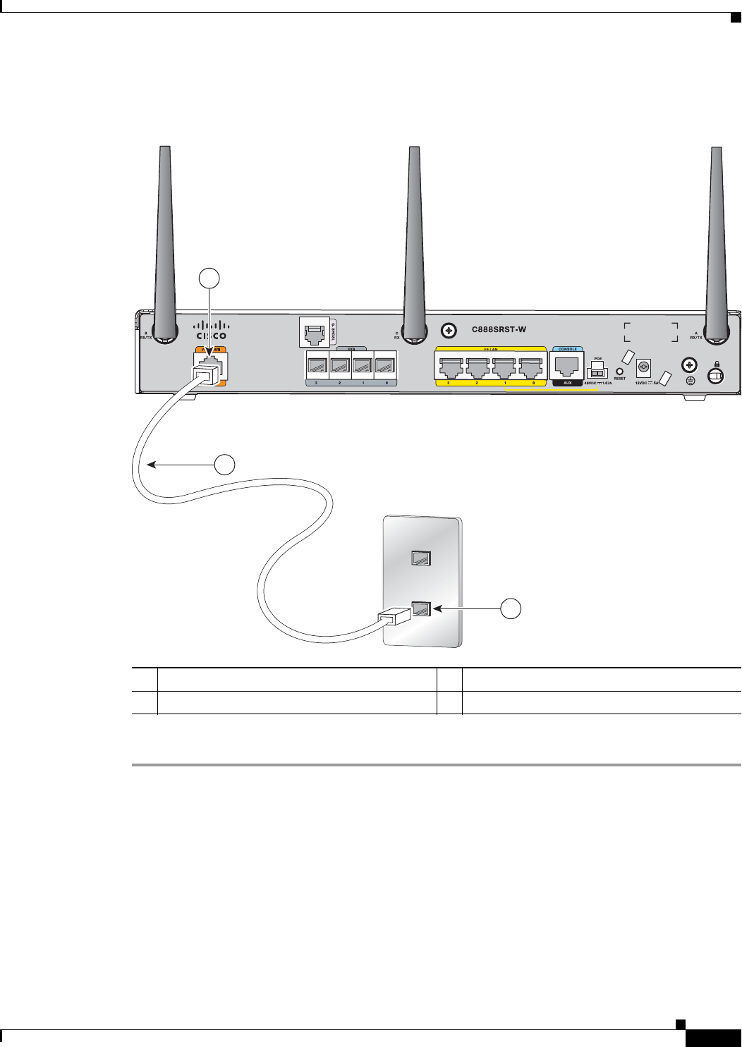
3-33
Cisco 860 Series, Cisco 880 Series, and Cisco 890 Series Integrated Services Routers Hardware Installation Guide
OL-16193-07
Chapter 3 Connecting the Router
Connecting a Small-form-factor Pluggable Module
Figure 3-30 shows a voice BRI line connection.
Figure 3-30 Connecting a Voice BRI Line
Step 2
Connect the other end of the cable to the RJ-45 telephone outlet or other device.
Connecting a Small-form-factor Pluggable Module
This section describes how to connect and remove an SFP module and contains the following
information:
•
Safety Warnings, page 3-34
•
Installing an SFP Module, page 3-34
1Voice BRI port 3Telephone outlet
2RJ-45 cable
2
41906
1
3
2

3-34
Cisco 860 Series, Cisco 880 Series, and Cisco 890 Series Integrated Services Routers Hardware Installation Guide
OL-16193-07
Chapter 3 Connecting the Router
Connecting a Small-form-factor Pluggable Module
•
Removing an SFP Module, page 3-35
•
Online Insertion and Removal, page 3-36
Safety Warnings
Laser Safety Warnings
Optical SFPs use a small laser to generate the fiber-optic signal. Keep the optical transmit and receive
ports covered whenever a cable is not connected to the port.
Warning
Because invisible laser radiation may be emitted from the aperture of the port when no fiber
cable is connected, avoid exposure to laser radiation and do not stare into open apertures.
Statement 70
Warning
Class 1 laser product.
Statement 1008
Warning
Do not stare into the laser beam.
Statement 1010
Warning
Invisible laser radiation present.
Statement 1016
Warning
Ultimate disposal of this product should be handled according to all national laws and
regulations.
Statement 1040
Warning
Invisible laser radiation may be emitted from the end of the unterminated fiber cable or
connector. Do not view directly with optical instruments. Viewing the laser output with certain
optical instruments (for example, eye loupes, magnifiers, and microscopes) within a distance of
100 mm may pose an eye hazard.
Statement 1056
Warning
Use of controls, adjustments, or performing procedures other than those specified may result in
hazardous radiation exposure.
Statement 1057
Installing an SFP Module
To connect and secure the SFP module, follow these steps:
Step 1
Slide the SFP into the SFP port connector until it locks into position (see Figure 3-31).
Tip
If the SFP uses a bale-clasp latch (see Figure 3-31), the handle should be on top of the SFP module.
3-35
Cisco 860 Series, Cisco 880 Series, and Cisco 890 Series Integrated Services Routers Hardware Installation Guide
OL-16193-07
Chapter 3 Connecting the Router
Connecting a Small-form-factor Pluggable Module
Figure 3-31 Installing an SFP Module
Caution
Caution Do not remove the optical port plugs from the SFP until you are ready to connect cabling.
Step 2
Connect the network cable to the SFP module.
Removing an SFP Module
Follow these steps to remove the SFP module from a Cisco 892F series router:
Step 1
Disconnect all cables from the SFP.
Warning
Because invisible laser radiation may be emitted from the aperture of the port when no fiber
cable is connected, avoid exposure to laser radiation and do not stare into open apertures.
Statement 70
Caution
The latching mechanism used on many SFPs locks the SFP into place when cables are connected. Do
not pull on the cabling in an attempt to remove the SFP.
Step 2
Disconnect the SFP latch. See Figure 3-32.
Note
SFP modules use various latch designs to secure the module in the SFP port. Latch designs are not linked
to SFP model or technology type. For information on the SFP technology type and model, see the label
on the side of the SFP.
94126
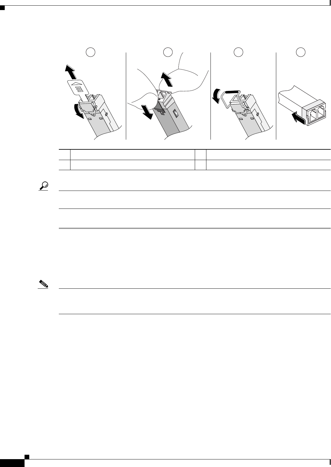
3-36
Cisco 860 Series, Cisco 880 Series, and Cisco 890 Series Integrated Services Routers Hardware Installation Guide
OL-16193-07
Chapter 3 Connecting the Router
Connecting a Small-form-factor Pluggable Module
Figure 3-32 Figure 5-42 Disconnecting SFP Latch Mechanisms
Tip
Use a pen, screwdriver, or other small straight tool to gently release a bale-clasp handle if you cannot
reach it with your fingers.
Step 3
Grasp the SFP on both sides and remove it from the router.
Online Insertion and Removal
Online insertion and removal (OIR) of the SFP module is supported on the Cisco 892F ISRs.
Note
If an SFP module is inserted with auto-failover or SFP media-type already configured, the port is forced
to the speed and duplex capability of the SFP. For a 100 base SFP, the speed is set to 100 and duplex can
be configured to either half or full. For a 1000 base SFP, the speed is set to 1000 and duplex is set to full.
1Sliding latch 3Bale-clasp latch
2Swing and slide latch 4Plastic collar latch
117722
1 2 3 4
A
B

3-37
Cisco 860 Series, Cisco 880 Series, and Cisco 890 Series Integrated Services Routers Hardware Installation Guide
OL-16193-07
Chapter 3 Connecting the Router
Verifying Connections
Verifying Connections
To verify that all devices are properly connected to the router, first turn on all the connected devices,
then check the LEDs. To verify router operation, refer to Table 3-3.
For full LED description, see Table 1-4 and Table 1-2.
Tabl e 3-3 Verifying the Router Operation
Power and Link LEDs to Check Normal Patterns
Power OK On when power is supplied to the router.
To servers, PCs,
workstations, or an
external Ethernet
switch connected to
the LAN ports
(FE0
1
, FE1, FE2, or
FE3)
LAN 0, LAN 1,
LAN 2, or LAN 3
On when the FE LAN port is physically connected to a
server, PC, workstation, or external Ethernet switch.
To FE WAN line WAN FE 4 On when the WAN Ethernet carrier has detected status.
Blinks when receiving or transmitting data.
To xDSL
2
line xDSL CD Green when the line is connected to the xDSL DSLAM
3
.
xDSL Data Green when receiving or sending data.
To ISDN line Data BRI LNK Green when the ISDN line is connected.
Data BRI B1 and
B2
Green when the channel is connected.
3G
4
WWAN
5
Green when service is established.
Slow blinking when searching for service.
RSSI
6
Amber when service is not established.
Green when signal strength is high.
Off or slow blinking when signal strength is low.
Fast blinking when signal strength is medium.
CDMA
7
Green when service is established.
GSM
8
Green when service is established.
To PPP
9
clients PPP Green when either a PPPoE
10
or PPPoA
11
client is running.
To VPN
12
tunnel VPN Green when a crypto session is running.

3-38
Cisco 860 Series, Cisco 880 Series, and Cisco 890 Series Integrated Services Routers Hardware Installation Guide
OL-16193-07
Chapter 3 Connecting the Router
Verifying Connections
To wireless LAN WLAN LINK Wireless LAN link status:
•
Green if at least one client is associated.
•
Off if no client is associated.
WLAN 2.4 GHz Wireless LAN 2.4-GHz status:
•
Green when radio is connected, SSID
13
is configured,
signal is being transmitted, and client is associated.
•
Slow blinking when radio is connected, SSID is
configured, and signal is being transmitted.
WLAN 5.0 GHz Wireless LAN 5.0-GHz status:
•
Green when radio is connected, SSID is configured,
signal is being transmitted, and client is associated.
•
Slow blinking when radio is connected, SSID is
configured, and signal is being transmitted.
PoE
14
PoE 0 (880 and
890 series only)
PoE power status:
•
Green when connected and powered.
•
Amber when there is a fault with the inline power
supply.
PoE 1 (880 and
890 series only)
PoE 2 (890 series
only)
PoE 3 (890 series
only)
SFP
15
EN Green when the interface is up.
SBlinking green indicates port speed. Slow blinking for
100Base SFPs and fast blinking for 1000Base SFPs.
To LAN GE/FE line
(860VAE models
only)
LAN Blinking when there is LAN activity (traffic in either
direction).
Off when the link is down.
Table 3-3 Verifying the Router Operation (continued)
Power and Link LEDs to Check Normal Patterns

3-39
Cisco 860 Series, Cisco 880 Series, and Cisco 890 Series Integrated Services Routers Hardware Installation Guide
OL-16193-07
Chapter 3 Connecting the Router
Verifying Connections
To DSL line
(860VAE models
only)
DSL LINK On when DSL WAN Mode is selected and DSL training
complete.
Blinking when DSL WAN Mode is selected but incomplete
DSL LinkUp state such as in-training (slow initially, fast
when almost be connected), or controller "OFF", or no cable
attached to DSL connector.
Off when the device is powered off; or GE_WAN_Mode is
selected.
DSL ACT On when the DSL interface is up.
Blinking when there is DSL WAN activity (traffic in either
direction).
Faster blinking when there is heavier traffic.
Off when the device is powered off or the DSL WAN
interface is down.
To WAN GE line
(860VAE models
only)
GE Mode On when GE WAN Mode is selected.
Off when the device is powered off or when
DSL_WAN_Mode is selected.
GE ACT On when the GE WAN interface is up.
Blinking when there is GE WAN activity (traffic in either
direction).
Off when the device is powered off or when the GE WAN
interface is down.
1. FE = Fast Ethernet.
2. xDSL = General term referring to various forms of DSL, including ADSL (asymmetric digital subscriber line), VDSL
(very-high-data-rate digital subscriber line), and G.SHDSL.
3. DSLAM = digital subscriber line access multiplexer.
4. 3G = Third-Generation.
5. WWAN = wireless WAN.
6. RSSI = Received Signal Strength Indicator.
7. CDMA = code division multiple access.
8. GSM = Global System for Mobile Communications.
9. PPP = Point-to-Point Protocol.
10. PPPoE = PPP over Ethernet.
11. PPPoA = PPP over ATM.
12. VPN = Virtual Private Network.
13. SSID = service set identifier.
14. PoE = Power over Ethernet.
15. SFP = small-form-factor pluggable.
Table 3-3 Verifying the Router Operation (continued)
Power and Link LEDs to Check Normal Patterns

3-40
Cisco 860 Series, Cisco 880 Series, and Cisco 890 Series Integrated Services Routers Hardware Installation Guide
OL-16193-07
Chapter 3 Connecting the Router
Verifying Connections

CHAPTER
4-1
Cisco 860 Series, Cisco 880 Series, and Cisco 890 Series Integrated Services Routers Hardware Installation Guide
OL-16193-07
4
Initial Configuration
This chapter provides instructions for initial configuration of the Cisco 860 series, 880 series, and 890
series Integrated Services Routers (ISRs). For the initial configuration, we recommend using
Cisco Configuration Professional (CP) Express. Cisco CP Express is a web-based graphical user
interface that guides you through initial configuration.
You may also initially configure your router by using the Cisco IOS command-line interface (CLI) or by
using the setup command facility. To create the initial configuration, the setup command facility prompts
you for basic information about your router and network.
This chapter contains the following sections:
•
Cisco Configuration Professional Express, page 4-1
•
Cisco IOS CLI, page 4-1
•
Setup Command Facility, page 4-3
•
Verifying the Initial Configuration, page 4-5
•
Initial Configuration of the Wireless Access Point, page 4-6
Note
Some SKUs may not include a default configuration file. If your router does not have a default
configuration file, go to the “Setup Command Facility” section on page 3 to configure the initial router
settings.
Cisco Configuration Professional Express
After you connect the cables and power up the router, we recommend that you use the Cisco CP Express
web-based application to configure the initial router settings.
For instructions on how to use Cisco CP Express to configure the router see Cisco CP Express User’s
Guide.
Cisco IOS CLI
To configure the initial router settings by using the Cisco IOS CLI, you must set up a console connection.
For instructions on how to set up a console connection, see the “Connecting a Terminal or PC to the
Console Port” section on page 3-7.

4-2
Cisco 860 Series, Cisco 880 Series, and Cisco 890 Series Integrated Services Routers Hardware Installation Guide
OL-16193-07
Chapter 4 Initial Configuration
Cisco IOS CLI
To configure the initial router settings using the Cisco IOS CLI, follow these steps:
Step 1
Set up a console connection to your router. The following message is displayed:
...
router con0 is now available
Step 2
Press Return. The following message is displayed:
Cisco Configuration Professional Express (Cisco CP Express) is installed on this device.
This feature requires the one-time use of the username "username1"
with the password "password1." The default username and password have a privilege level of
15.
Please change these publicly known initial credentials using Cisco CP Express or the Cisco
IOS CLI.
Here are the Cisco IOS commands.
username <myuser> privilege 15 secret 0 <mypassword>
no username username1
Replace <myuser> and <mypassword> with the username and password you want to use.
For more information about Cisco CP please follow the instructions in the QUICK START
GUIDE for your router...
...
User Access Verification
Username:
Step 3
Enter the username username1, and press Return or Enter. The following prompt is displayed:
Password:
Step 4
Enter the password password1, and press Return or Enter. The following prompt is displayed:
Router#
A message is displayed that is similar to the first warning message. The message directs you to change
the username and password.
You are now in privileged EXEC mode.
Note
You m ust chang e the usern a me an d pas s word befo r e you log off the rout er. You c annot use the
username username1 or password password1 after you log off from this session.
Step 5
Enter configuration mode using the following commands.
Router#
Router#config t
Router(config)#
Router(config)#username username privilege 15 secret 0 password
Step 6
To change the username and password, enter the following at the prompt:
username username privilege 15 secret 0 password
The username and password are the username and password that you determine.
To continue using the Cisco IOS CLI for initial configuration, see the applicable configuration
procedures in Cisco 860 Series, Cisco 880 Series, and Cisco 890 Series Integrated Services Routers
Software Configuration Guide.

4-3
Cisco 860 Series, Cisco 880 Series, and Cisco 890 Series Integrated Services Routers Hardware Installation Guide
OL-16193-07
Chapter 4 Initial Configuration
Setup Command Facility
Note
Save your configuration changes regularly to avoid losing them during resets, power cycles, or
power outages. Use the copy running-config startup-config command at the privileged EXEC
mode prompt (Router#) to save the configuration to NVRAM.
Step 7
Verify the initial configuration. See the “Verifying the Initial Configuration” section on page 4-5.
Setup Command Facility
The setup command facility guides you through the configuration process by prompting you for the
specific information that is needed to configure your system. Use the setup command facility to
configure a hostname for the router, to set passwords, and to configure an interface for communication
with the management network.
To use the setup command facility, you must set up a console connection with the router and enter the
privileged EXEC mode.
Note
For instructions on how to set up a console connection, see the “Connecting a Terminal or PC to
the Console Port” section on page 3-7.
To configure the initial router settings by using the setup command facility, follow these steps:
Step 1
Set up a console connection to your router, and enter privileged EXEC mode. For instructions on how
to enter privileged EXEC mode, see Step 1 through Step 4 in the “Cisco IOS CLI” section on page 4-1.
Step 2
In privileged EXEC mode, at the prompt, enter setup.
yourname# setup
The following message is displayed:
--- System Configuration Dialog ---
Continue with configuration dialog? [yes/no]:
You are now in the setup command facility.
The prompts in the setup command facility vary, depending on your router model, on the installed
interface modules, and on the software image. The following steps and the user entries (in bold) are
shown as examples only.
Note
If you make a mistake while using the setup command facility, you can exit and run the setup
command facility again. Press Ctrl-C, and enter the setup command at the privileged EXEC
mode prompt (Router#). For more information on using the setup command facility, see “The
Setup Command” chapter in Cisco IOS Configuration Fundamentals Command Reference,
Release 12.2T.
Step 3
To proceed using the setup command facility, enter yes.
Continue with configuration dialog? [yes/no]: yes

4-4
Cisco 860 Series, Cisco 880 Series, and Cisco 890 Series Integrated Services Routers Hardware Installation Guide
OL-16193-07
Chapter 4 Initial Configuration
Setup Command Facility
Step 4
When the following messages appear, enter yes to enter basic management setup.
At any point you may enter a question mark '?' for help.
Use ctrl-c to abort configuration dialog at any prompt.
Default settings are in square brackets '[]'.
Basic management setup configures only enough connectivity
for management of the system, extended setup will ask you
to configure each interface on the system
Would you like to enter basic management setup? [yes/no]: yes
Step 5
Enter a hostname for the router (this example uses Router).
Configuring global parameters:
Enter host name [Router]: Router
Step 6
Enter an enable secret password. This password is encrypted (more secure) and cannot be seen when
viewing the configuration.
The enable secret is a password used to protect access to
privileged EXEC and configuration modes. This password, after
entered, becomes encrypted in the configuration.
Enter enable secret: xxxxxx
Step 7
Enter an enable password that is different from the enable secret password. This password is not
encrypted (less secure) and can be seen when viewing the configuration.
The enable password is used when you do not specify an
enable secret password, with some older software versions, and
some boot images.
Enter enable password: xxxxxx
Step 8
Enter the virtual terminal password, which prevents unauthenticated access to the router through ports
other than the console port.
The virtual terminal password is used to protect
access to the router over a network interface.
Enter virtual terminal password: xxxxxx
Step 9
Respond to the following prompts as appropriate for your network.
Configure SNMP Network Management? [yes]:
Community string [public]:
A summary of the available interfaces is displayed.
Step 10
Choose one of the available interfaces for connecting the router to the management network.
Enter interface name used to connect to the
management network from the above interface summary: fastethernet4
Step 11
Respond to the following prompts as appropriate for your network.
Configuring interface FastEthernet4:
Use the 100 Base-TX (RJ-45) connector? [yes]: yes
Operate in full-duplex mode? [no]: yes
Configure IP on this interface? [yes]: yes
IP address for this interface: 172.1.2.3
Subnet mask for this interface [255.255.0.0] : 255.255.0.0
Class B network is 172.1.0.0, 26 subnet bits; mask is /16
The configuration is displayed:
The following configuration command script was created:

4-5
Cisco 860 Series, Cisco 880 Series, and Cisco 890 Series Integrated Services Routers Hardware Installation Guide
OL-16193-07
Chapter 4 Initial Configuration
Verifying the Initial Configuration
hostname Router
enable secret 5 $1$D5P6$PYx41/lQIASK.HcSbfO5q1
enable password xxxxxx
line vty 0 4
password xxxxxx
snmp-server community public
!
no ip routing
!
interface FastEthernet4
no shutdown
speed 100
duplex auto
ip address 172.1.2.3 255.255.0.0
!
Step 12
Respond to the following prompts. Enter 2 to save the initial configuration.
[0] Go to the IOS command prompt without saving this config.
[1] Return back to the setup without saving this config.
[2] Save this configuration to nvram and exit.
Enter your selection [2]: 2
Building configuration...
Use the enabled mode 'configure' command to modify this configuration.
Press RETURN to get started! RETURN
The user prompt is displayed.
Router>
Step 13
Verify the initial configuration. See the “Verifying the Initial Configuration” section on page 4-5 for
verification procedures.
After the initial configuration file is created, you can use the Cisco IOS CLI to perform additional
configuration.
Verifying the Initial Configuration
To verify that the new interfaces are operating correctly, perform the following tests:
•
To verify that the interfaces and line protocol are in the correct state—up or down—enter the show
interfaces command.
•
To display a summary status of the interfaces configured for IP, enter the show ip interface brief
command.
•
To verify that you configured the correct hostname and password, enter the show configuration
command.
After you complete and verify the initial configuration, you can configure your Cisco router for specific
functions.

4-6
Cisco 860 Series, Cisco 880 Series, and Cisco 890 Series Integrated Services Routers Hardware Installation Guide
OL-16193-07
Chapter 4 Initial Configuration
Initial Configuration of the Wireless Access Point
Initial Configuration of the Wireless Access Point
The embedded wireless access point (AP) runs its own IOS. You can initially configure the embedded
wireless AP by using one of the following methods:
•
Cisco Configuration Professional (CP) Express
•
Setup command facility on the embedded wireless device
For information on how to do basic wireless configuration on your router see the “Basic Wireless
Device” chapter of the Cisco 860 Series, Cisco 880, and Cisco 890 Series Integrated Services Routers
Software Configuration Guide.

A-1
Cisco 860 Series, Cisco 880 Series, and Cisco 890 Series Integrated Services Routers Hardware Installation Guide
OL-16193-07
APPENDIX
A
Technical Specifications
This appendix provides router, port, and cabling specifications for the Cisco 860 series, Cisco 880
series, and Cisco 890 series Integrated Services Routers (ISRs). It contains the following sections:
•
Router Specifications, page A-2
•
Wireless Access Point, page A-3
•
FE and GE Port Pinouts, page A-3
•
Console and Auxiliary Port Connector Pinouts, page A-4
•
FXS and FXO Port Connector Pinouts, page A-5
•
VDSL2 Port Connector Pinouts, page A-5
•
ADSL2+ Port Connector Pinouts, page A-5
•
V.92 Port Connector Pinouts, page A-6
•
G.SHDSL Port Connector Pinouts, page A-6
•
Data BRI Port Connector Pinouts, page A-7
•
Voice ISDN BRI Interface Pin Numbers and Functions, page A-7
•
SFP Port Connector Pinouts, page A-8
•
Cable Specifications, page A-8
Warning
Ultimate disposal of this product should be handled according to all national laws and
regulations.
Statement 1040
Note
For compliance and safety information, see Regulatory Compliance and Safety Information Roadmap
that was shipped with the router and Regulatory Compliance and Safety Information for Cisco 800
Series and SOHO Series Routers.
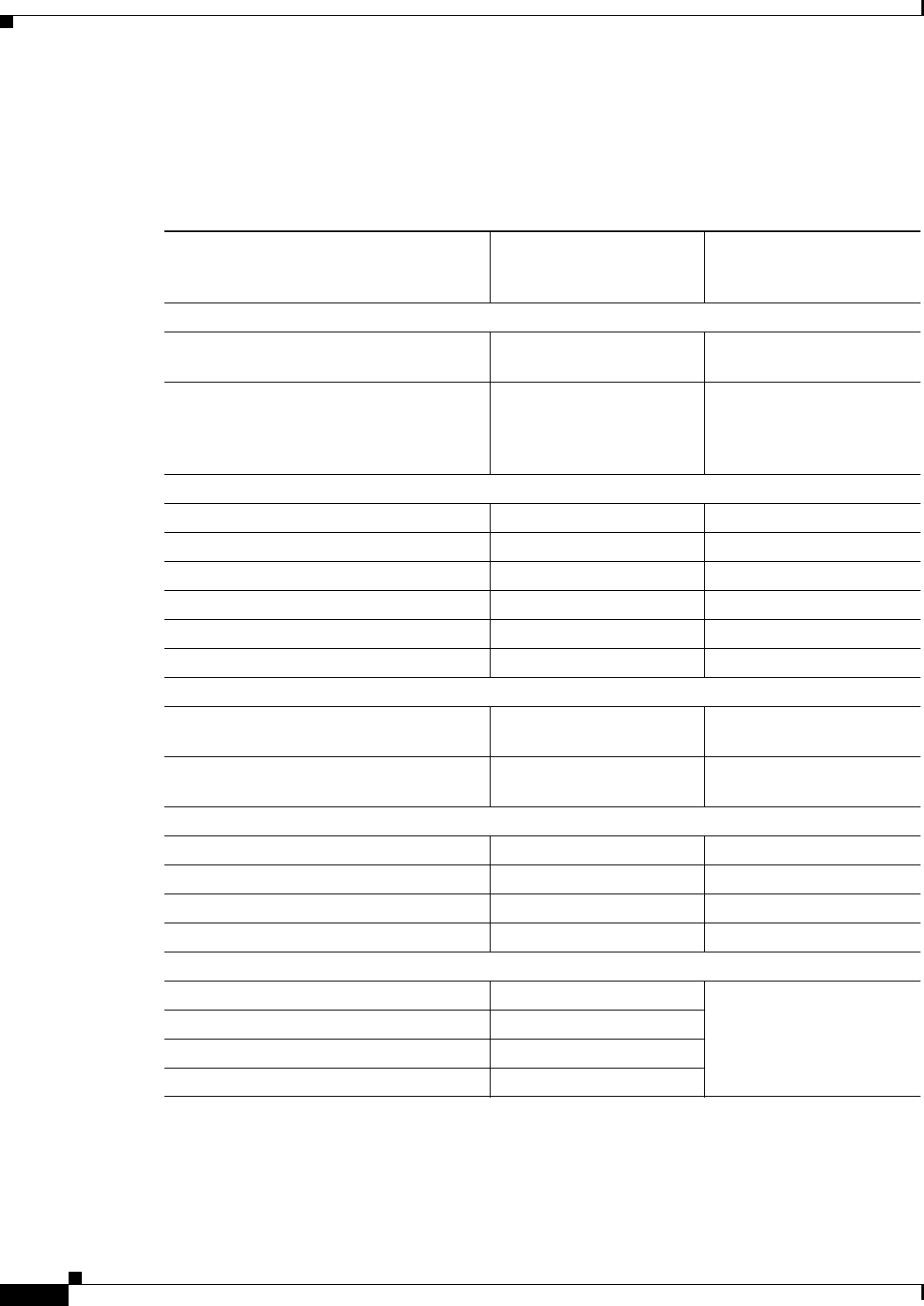
A-2
Cisco 860 Series, Cisco 880 Series, and Cisco 890 Series Integrated Services Routers Hardware Installation Guide
OL-16193-07
Appendix A Technical Specifications
Router Specifications
Router Specifications
Table A-1 lists the system specifications for the routers.
Tabl e A-1 Router Specifications
Description
Design Specification
(all models except
Cisco 860VAE series)
Design Specification
Cisco 860VAE series
Physical Dimensions
Dimensions with antenna and rubber
feet (H x W x D)
1.9 x 12.8 x 10.4 in. 1.75 x 9.5 x 9 in.
Weight (not including desktop power
supply)
5.5 lb (2.5 kg), maximum 3 lb (1.4 kg)
The total weight depends
on customer-selected
options.
Environmental Operating Ranges
Nonoperating temperature –4 to 149°F (–20 to 65°C) –4 to 149°F (–20 to 65°C)
Nonoperating humidity 5 to 95% relative humidity 5 to 95% relative humidity
Nonoperating altitude 0 to 15,000 ft (4570 m) 0 to 15,000 ft (4570 m)
Operating temperature 32 to 104°F (0 to 40°C) 32 to 104°F (0 to 40°C)
Operating humidity 10 to 85% relative humidity 10 to 85% relative humidity
Operating altitude 0 to 10,000 ft (3000 m) 0 to 10,000 ft (3000 m)
Acoustic
Acoustic: Sound Pressure
(Typical/Maximum)
Low speed 31.4 dBa
High speed 44.1 dBa
N/A, no fan
Acoustic: Sound Power
(Typical/Maximum)
Low speed 38.9 dBA
High speed 51.7 dBa
N/A, no fan
Router Power Adapter
Input voltage 85 to 264 VAC 85 to 264 VAC
Input frequency 47 to 63 Hz 47 to 63 Hz
Power output 60 W, maximum 30 W, maximum
Output voltages +12 VDC +12 VDC
Inline Power-over-Ethernet Adapter
Input voltage 85 to 264 VAC not supported
Input frequency 47 to 63 Hz
Power output 80 W, maximum
Output voltage –48 VDC

A-3
Cisco 860 Series, Cisco 880 Series, and Cisco 890 Series Integrated Services Routers Hardware Installation Guide
OL-16193-07
Appendix A Technical Specifications
Wireless Access Point
Wireless Access Point
Table A-2 lists the specifications for the wireless access point (AP).
FE and GE Port Pinouts
Table A-3 describes the RJ-45 connector pinouts for Fast Ethernet (FE) ports with Power over Ethernet
(PoE). Some models support PoE using an optional module, and some models do not support PoE. For
ports that do not support PoE, pins 4, 5, 7, and 8 are not connected.
•
Cisco 860VAE and 860VAE-K9 ISRs do not support PoE.
•
Cisco 880 series ISRs can include an optional PoE module that provides power to 802.3af-compliant
devices connected to FE ports 0 and 1.
•
Cisco 890 series ISRs can include an optional PoE module that provides power to 802.3af-compliant
devices connected to FE ports 0, 1, 2, and 3.
Tabl e A-2 Wireless Access Point Specifications
Description Design Specification
Radio technology IEEE 802.11n draft 2.0 standard compliant. 2x3
MIMO
1
radio. Backward compatible with
802.11b/g and 802.11a (Cisco 890 series routers).
1. MIMO = Multiple Input/Multiple Output.
Operating frequency
Cisco 860 series and 880 series ISRs
2.4-GHz radio band
Cisco 890 series ISRs
2.4 and 5-GH radio bands
Channels Country-specific 20 and 40 MHz
PHY Data rate 802.11b up to 11 Mb/s
802.11g up to 54 Mb/s
802.11n up to 300 Mb/s
Tabl e A-3 Ethernet FE LAN Port Pinouts
Pin Function
1RX+
1
2RX–
3TX+
2
4PoE—optional
5PoE—optional
6TX–
7PoE—optional
8PoE—optional

A-4
Cisco 860 Series, Cisco 880 Series, and Cisco 890 Series Integrated Services Routers Hardware Installation Guide
OL-16193-07
Appendix A Technical Specifications
Console and Auxiliary Port Connector Pinouts
Table A-4 describes the RJ-45 connector pinouts for the Gigabit Ethernet (GE) ports of the Cisco
860VAE and 860VAE-K9 ISRs.
Console and Auxiliary Port Connector Pinouts
Table A-5 lists the pinouts for the console and auxiliary port connectors.
1. RX = Receive
2. TX = Transmit
Tabl e A-4 Ethernet GE Port Pinouts
Pin
GE Signal
(LAN and WAN)
1Tx A+
1
1. TX = Transmit
2Tx A-
3Rx B+
2
2. RX = Receive
4Tx C+
5Tx C-
6Rx B-
7Rx D+
8Rx D-
Tabl e A-5 Console and Auxiliary Port Connector Pinouts
RJ-45 Pin Function
1RTS
2DTR
3TXD
4GND
5GND
6RXD
7DSR
8CTS

A-5
Cisco 860 Series, Cisco 880 Series, and Cisco 890 Series Integrated Services Routers Hardware Installation Guide
OL-16193-07
Appendix A Technical Specifications
FXS and FXO Port Connector Pinouts
FXS and FXO Port Connector Pinouts
Table A-7 lists the FXS and FXO connector pinouts.
VDSL2 Port Connector Pinouts
Table A-7 lists the VDSL2 connector pinouts.
ADSL2+ Port Connector Pinouts
Table A-7 lists the ADSL2+ connector pinouts.
Tabl e A-6 FXS and FXO Connector Pinouts (RJ-11-to-RJ-45)
Pin Signal
1NC
2NC
3TIP
4RING
5NC
6NC
Tabl e A-7 VDSL2 Connector Pinouts (RJ-11-to-RJ-45)
RJ-11 Pin Function
1Unused
2Unused
3TIP
4RING
5Unused
6Unused
Tabl e A-8 ADSL2+ Connector Pinouts (RJ-11)
RJ-11 Pin Function
1Unused
2Unused
3TIP
4RING
5Unused
6Unused

A-6
Cisco 860 Series, Cisco 880 Series, and Cisco 890 Series Integrated Services Routers Hardware Installation Guide
OL-16193-07
Appendix A Technical Specifications
V.92 Port Connector Pinouts
V.92 Port Connector Pinouts
Table A-9 lists the V.92 connector pinouts.
G.SHDSL Port Connector Pinouts
Table A-10 lists the pinouts for the symmetrical high-speed DSL (G.SHDSL) WAN port for two-pair
products, including the following router model(s):
•
C888
Table A-11 lists the pinouts for the symmetrical high-speed DSL (G..SHDSL) WAN port for four-pair
products, including the following router models:
•
C888E
•
C888EW
•
C888EA
Tabl e A-9 V.92 Connector Pinouts (RJ-11-to-RJ-45)
RJ-11 Pin Function
1Unused
2Unused
3TIP
4RING
5Unused
6Unused
Tabl e A-10 G.SHDSL WAN Port Pinouts for Two-Pair Products
Pin Function
1Unused
2TIP (Port1)
3TIP (Port0)
4RING (Port0)
5RING (Port1)
6Unused
Tabl e A-11 G.SHDSL WAN Port Pinouts for Four-Pair Products
Pin Function
1TIP (Port1)
2RING (Port1)
3TIP (Port2)
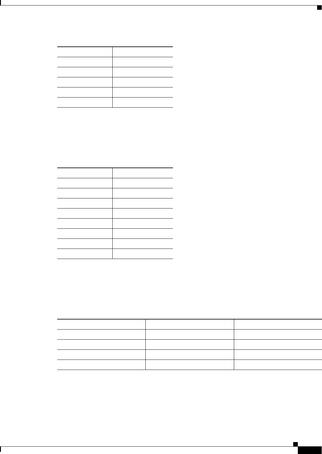
A-7
Cisco 860 Series, Cisco 880 Series, and Cisco 890 Series Integrated Services Routers Hardware Installation Guide
OL-16193-07
Appendix A Technical Specifications
Data BRI Port Connector Pinouts
Data BRI Port Connector Pinouts
Table A-12 lists the pinouts for the Data BRI port.
Voice ISDN BRI Interface Pin Numbers and Functions
Table A-13 lists the interface pin numbers and functions for the voice ISDN BRI port.
4TIP (Port0)
5RING (Port0)
6RING (Port2)
7TIP (Port3)
8RING (Port3)
Table A-11 G.SHDSL WAN Port Pinouts (continued)for Four-Pair Products
Pin Function
Tabl e A-12 Data BRI Port Pinouts
Pin Function
1Unused
2Unused
3TXP
4RXP
5TXN
6TXN
7Unused
8Unused
Tabl e A-13 Interface Pin Numbers and Functions
ISDN BRI NT/TE Card NT Interface
1
1. Use a straight-through cable for NT interfaces.
TE Interface
2
2. Use a crossover cable for TE interfaces.
Pin 3/T+ Pin 3/R+ Pin 3/T+
Pin 4/R+ Pin 4/T+ Pin 4/R+
Pin 5/R- Pin 5/T- Pin 5/R-
Pin 6/T- Pin 6/R- Pin 6/T-

A-8
Cisco 860 Series, Cisco 880 Series, and Cisco 890 Series Integrated Services Routers Hardware Installation Guide
OL-16193-07
Appendix A Technical Specifications
SFP Port Connector Pinouts
SFP Port Connector Pinouts
Table A-14 lists the pinouts for the SFP port.
Cable Specifications
This section provides specifications for the following Ethernet cables:
•
Straight-through cable
•
Crossover cable
Because of the autocrossover (autosensing) function, both straight-through and crossover cables can be
used for the Ethernet LAN port.
Tabl e A-14 SFP Port Pinouts
Pin Function
1TX Ground
2TX Fault
3TX disable
4Module definition 2
5Module definition 1
6Module definition 0
7Rate Select
8Loss of signal
9Receiver ground
10 Receiver ground
11 Receiver ground
12 Inverted received data out
13 Received data out
14 Receiver ground
15 Receiver power
16 Transmitter power
17 Transmitter ground
18 Transmit data in
19 Inverted transmit data in
20 Transmitter ground

A-9
Cisco 860 Series, Cisco 880 Series, and Cisco 890 Series Integrated Services Routers Hardware Installation Guide
OL-16193-07
Appendix A Technical Specifications
Cable Specifications
Ethernet Cable Specifications
Table A-15 lists the specifications that apply to both straight-through and crossover Ethernet cables.
Maximum Cable Length
The maximum length for the Ethernet cables that connect equipment to the router is 328 feet
(100 meters). This length is also the maximum distance between the router and the equipment connected
to it.
Tabl e A-15 Ethernet Cable Specifications
Type Category
10BASE-T Category 3 or 5
100BASE-T Category 5 or higher
1000BASE-T Category 5 or higher

A-10
Cisco 860 Series, Cisco 880 Series, and Cisco 890 Series Integrated Services Routers Hardware Installation Guide
OL-16193-07
Appendix A Technical Specifications
Cable Specifications