Cisco Systems VP1900XX PCS GSM Base Station User Manual
Cisco Systems Inc PCS GSM Base Station
UserManual.wiki
>
Cisco Systems
>
VP1900XX User Manual
>
Install Manual
Contents
1.
User Manual
2.
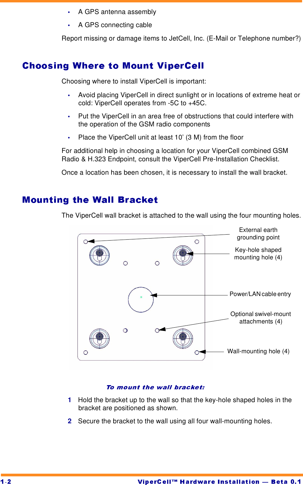
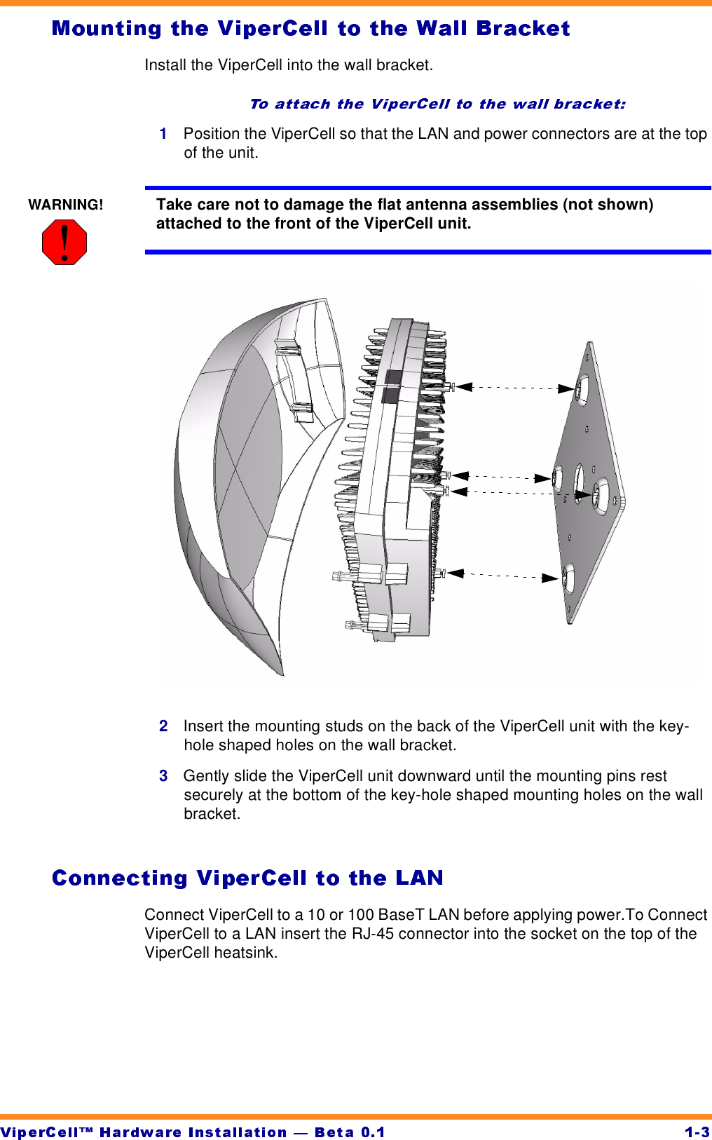
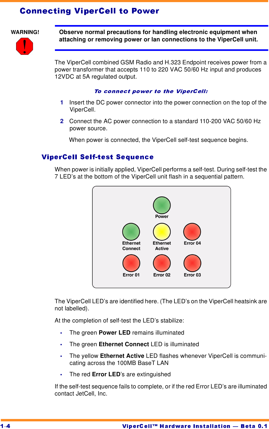
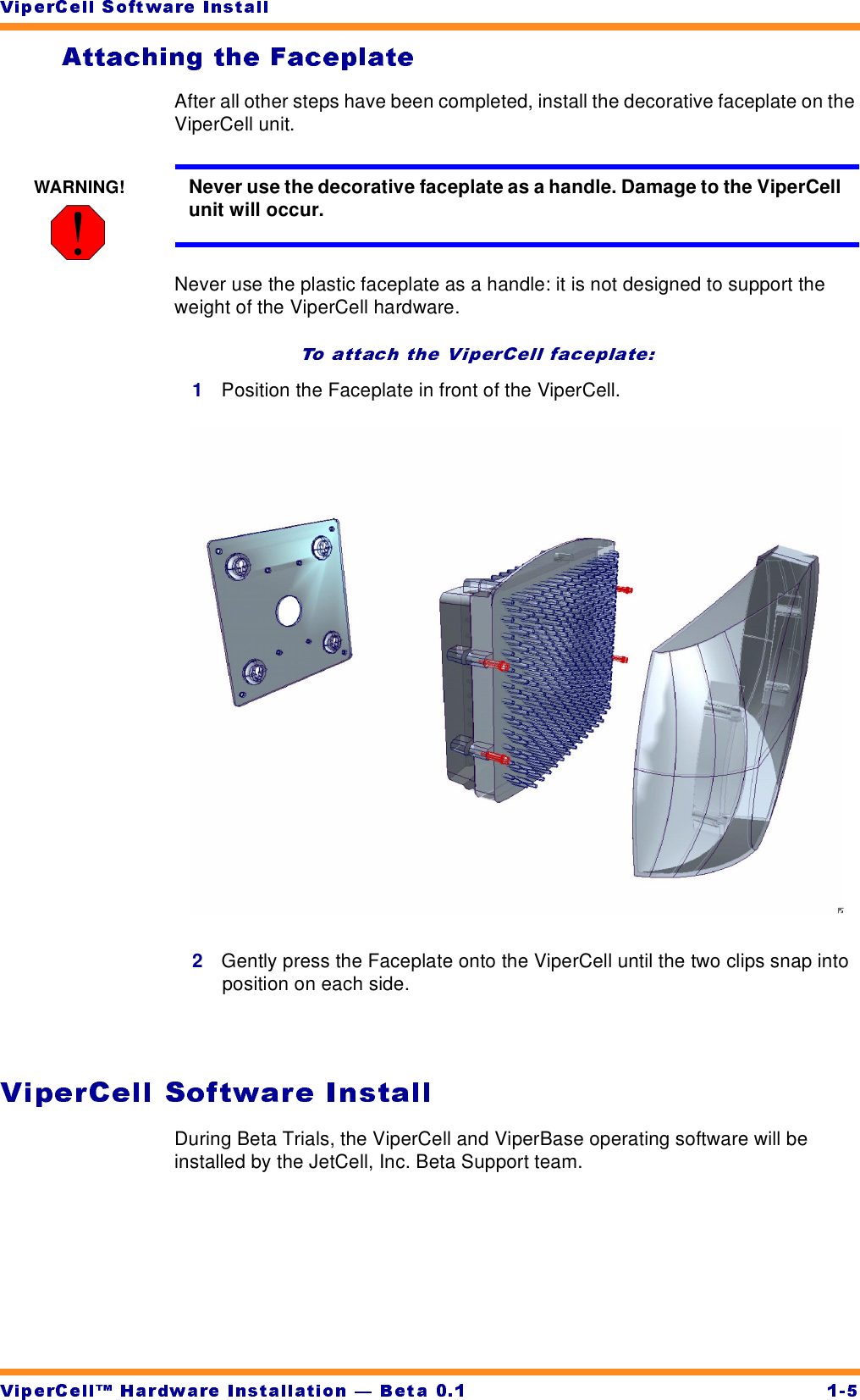
Install Manual
Install Manual
Navigation menu
Upload a User Manual
Namespaces
Wiki Guide
HTML
PDF
Info
Views
User Manual
Discussion / Help
Navigation