Cisco Systems VP1900XX PCS GSM Base Station User Manual
Cisco Systems Inc PCS GSM Base Station
Contents
- 1. User Manual
- 2. Install Manual
Install Manual

JetCell, Inc.
+DUGZDUH
,QVWDOODWLRQ
%HWD
9LSHU&HOO

ViperCell™ I&C Guide - Beta 1.0
JetCell Confidential
The information contained in this document is the property of JetCell, Inc. Except as
specifically authorized in writing by JetCell, the holder of this document shall keep the
information contained herein confidential and protect it from disclosure and dissemina-
tion to third parties in whole or in part and use same for evaluation purposes only. Cert-
tain inventions described herein may be the subject of pending U.S. and international
patent applications.
This document, whether published or unpublished, is protected as a copyrighted work
and may not be copied, adapted, displayed or modified without written consent of Jet-
Cell, Inc. Report infringements to
infringement@jetcell.com
.
The contents of this document are provided for information purposes only and are sub-
ject to modification by JetCell, Inc. without notice. No representation or warranty is
made as to the completeness or accuracy of the information contained herein, including
but not limited to information concerning the suitability or performance of the product or
application, merchantability or fitness for any particular purpose.
The following are trademarks of JetCell, Inc.: GoIP, RAP, SmartCell, SureTrack, V7M,
V7X, ViperBase, ViperCell, ViperWatch.
ViperCell Hardware Installation
Beta Release 0.1
© Copyright 1999 JetCell Incorporated. All rights reserved.
-HW&HOO,QF
7DEOHRI&RQWHQWV
ViperCell Hardware Installation
Installing ViperCell Hardware ............................................................. 1-1
Unpacking ViperCell .......................................................................... 1-1
Choosing Where to Mount ViperCell ................................................... 1-2
Mounting the Wall Bracket ................................................................. 1-2
Mounting the ViperCell to the Wall Bracket ......................................... 1-3
Connecting ViperCell to the LAN ........................................................ 1-3
Connecting ViperCell to Power ........................................................... 1-4
ViperCell Self-test Sequence .............................................................. 1-4
Attaching the Faceplate ..................................................................... 1-5
ViperCell Software Install........................................................................... 1-5

-HW&HOO,QF
9LSHU&HOO+DUGZDUH,QVWDOODWLRQ
A complete ViperNet Installation requires the installation of four major compo-
nents:
•The ViperCell combined GSM Radio and H.323 Endpoint hardware
•The ViperWatch Operations, Administration, and Maintenance (OA&M)
software
•The ViperBase GSM-Enhanced H.323 Gatekeeper software
•The V7M Interworking software
This Installation and Commissioning (I&C) Guide describes how to install the
ViperCell combined GSM Radio and H.323 Endpoint hardware. Installation of
ViperWatch, ViperBase, and V7M software are each described in their own Instal-
lation and Commissioning Guide.
Before beginning the procedures described in this document please consult the
ViperCell Pre-Installation Checklist to determine whether your site is ready to
receive ViperCell hardware.
Installing ViperCell hardware involves the following major steps:
•Mount the ViperCell bracket to the wall
•Attach the ViperCell hardware to the bracket
•Connect the ViperCell hardware to a 10 or 100 BaseT LAN
•Connect the ViperCell hardware to power and verify the self-test sequence
•Attach the decorative faceplate
Completion of Hardware Installation is followed by installation of the ViperWatch
OA&M Software.
Each ViperCell is shipped with the following:
•A ViperCell combined GSM Radio and H.323 Endpoint assembly
•An AC/DC power transformer that accepts a 110-220 VAC input, and pro-
duces a 12 VDC 5A output
•A country-specific power cord
•A bracket for mounting the ViperCell to a wall
•A decorative faceplate
•A package of screws used to attach the bracket and faceplate
If you have ordered the GPS option, this list is supplemented by the following two
items:
-
•A GPS antenna assembly
•A GPS connecting cable
Report missing or damage items to JetCell, Inc. (E-Mail or Telephone number?)
Choosing where to install ViperCell is important:
•Avoid placing ViperCell in direct sunlight or in locations of extreme heat or
cold: ViperCell operates from -5C to +45C.
•Put the ViperCell in an area free of obstructions that could interfere with
the operation of the GSM radio components
•Place the ViperCell unit at least 10’ (3 M) from the floor
For additional help in choosing a location for your ViperCell combined GSM
Radio & H.323 Endpoint, consult the ViperCell Pre-Installation Checklist.
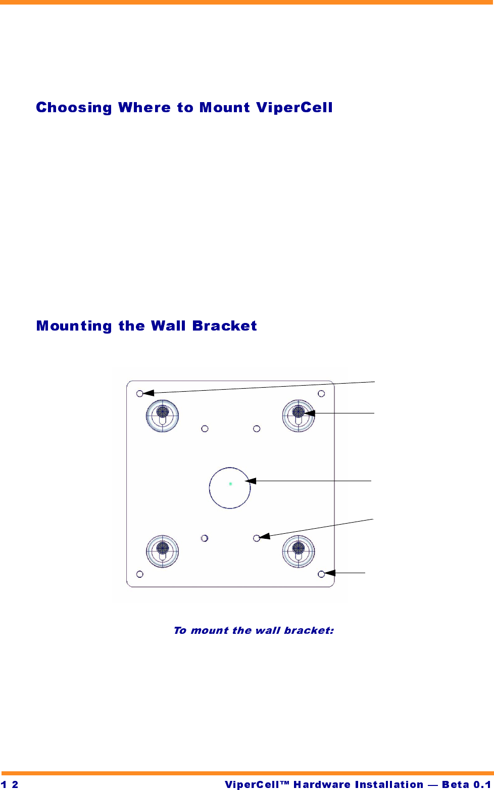
Once a location has been chosen, it is necessary to install the wall bracket.
The ViperCell wall bracket is attached to the wall using the four mounting holes.
1Hold the bracket up to the wall so that the key-hole shaped holes in the
bracket are positioned as shown.
2Secure the bracket to the wall using all four wall-mounting holes.
Wall-mounting hole (4)
External earth
grounding point
Key-hole shaped
mounting hole (4)
Optional swivel-mount
attachments (4)
Power/LAN cable entry
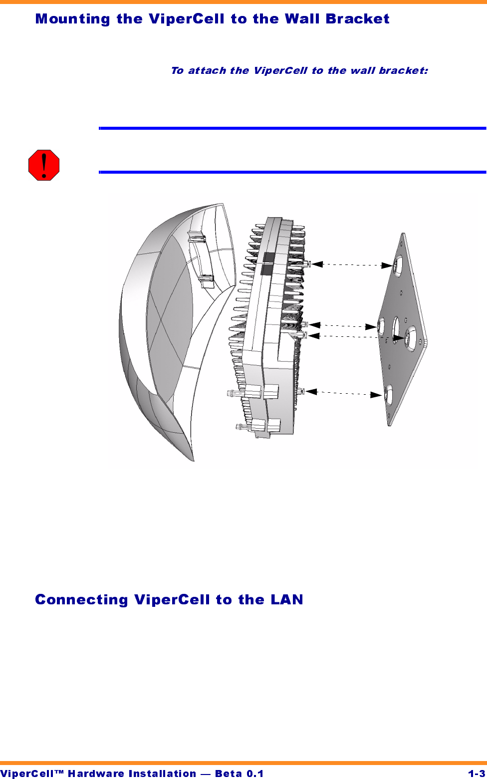
Install the ViperCell into the wall bracket.
1Position the ViperCell so that the LAN and power connectors are at the top
of the unit.
WARNING! Take care not to damage the flat antenna assemblies (not shown)
attached to the front of the ViperCell unit.
2Insert the mounting studs on the back of the ViperCell unit with the key-
hole shaped holes on the wall bracket.
3Gently slide the ViperCell unit downward until the mounting pins rest
securely at the bottom of the key-hole shaped mounting holes on the wall
bracket.
Connect ViperCell to a 10 or 100 BaseT LAN before applying power.To Connect
ViperCell to a LAN insert the RJ-45 connector into the socket on the top of the
ViperCell heatsink.
-
WARNING! Observe normal precautions for handling electronic equipment when
attaching or removing power or lan connections to the ViperCell unit.
The ViperCell combined GSM Radio and H.323 Endpoint receives power from a
power transformer that accepts 110 to 220 VAC 50/60 Hz input and produces
12VDC at 5A regulated output.
1Insert the DC power connector into the power connection on the top of the
ViperCell.
2Connect the AC power connection to a standard 110-200 VAC 50/60 Hz
power source.
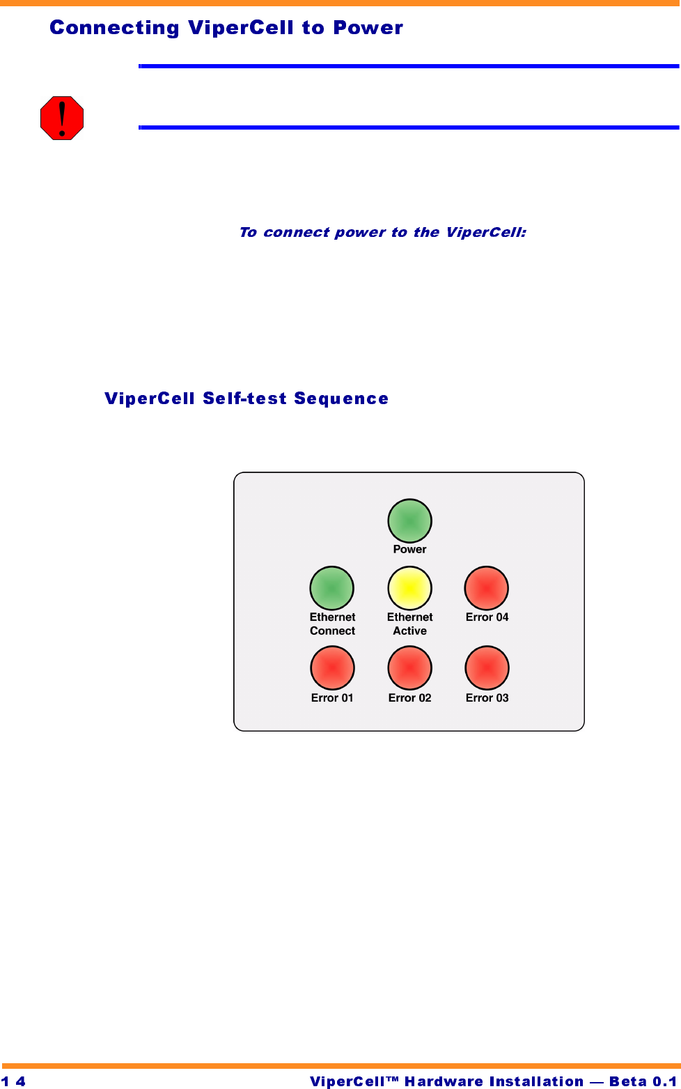
When power is connected, the ViperCell self-test sequence begins.
When power is initially applied, ViperCell performs a self-test. During self-test the
7 LED’s at the bottom of the ViperCell unit flash in a sequential pattern.
The ViperCell LED’s are identified here. (The LED’s on the ViperCell heatsink are
not labelled).
At the completion of self-test the LED’s stabilize:
•The green Power LED remains illuminated
•The green Ethernet Connect LED is illuminated
•The yellow Ethernet Active LED flashes whenever ViperCell is communi-
cating across the 100MB BaseT LAN
•The red Error LED’s are extinguished
If the self-test sequence fails to complete, or if the red Error LED’s are illuminated
contact JetCell, Inc.
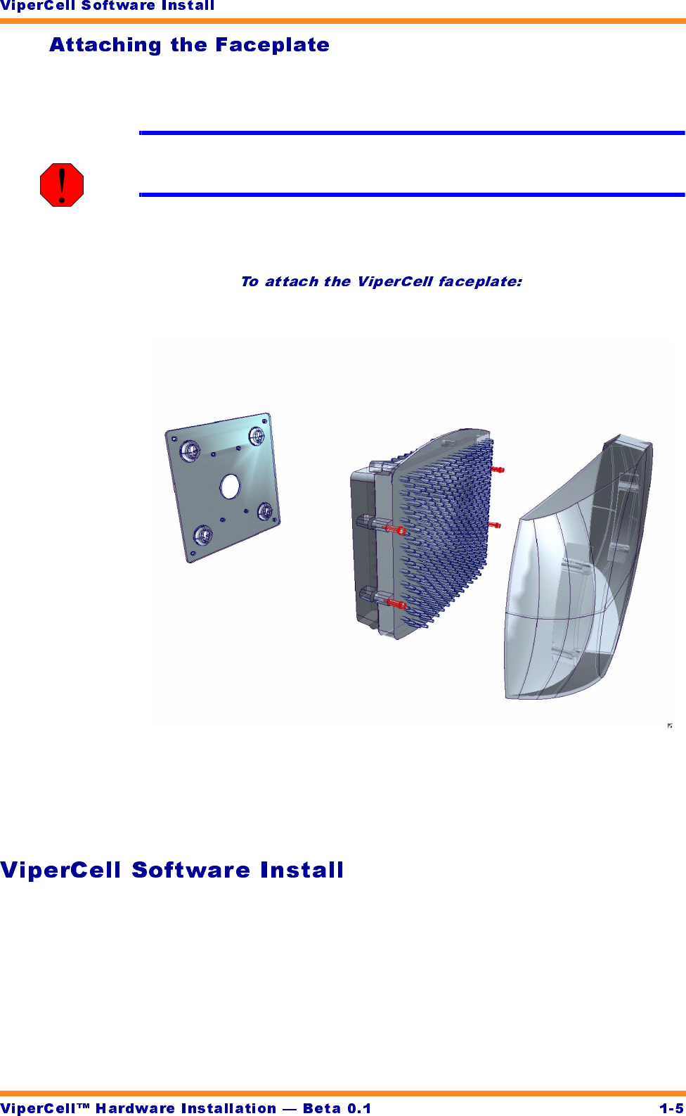
After all other steps have been completed, install the decorative faceplate on the
ViperCell unit.
WARNING! Never use the decorative faceplate as a handle. Damage to the ViperCell
unit will occur.
Never use the plastic faceplate as a handle: it is not designed to support the
weight of the ViperCell hardware.
1Position the Faceplate in front of the ViperCell.
2Gently press the Faceplate onto the ViperCell until the two clips snap into
position on each side.
During Beta Trials, the ViperCell and ViperBase operating software will be
installed by the JetCell, Inc. Beta Support team.
-