Cisco Systems WCS-BTS1 Ripwave Base Station User Manual Appendix L Antenna Power Cable Selection
Cisco Systems, Inc Ripwave Base Station Appendix L Antenna Power Cable Selection
UserManual.wiki
>
Cisco Systems
>
WCS-BTS1 User Manual
>
Manual 2
Contents
1.
Manual 1
2.
Manual 2
Manual 2
Navigation menu
Upload a User Manual
Namespaces
Wiki Guide
HTML
PDF
Info
Views
User Manual
Discussion / Help
Navigation
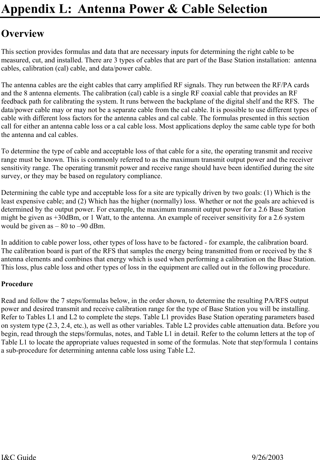
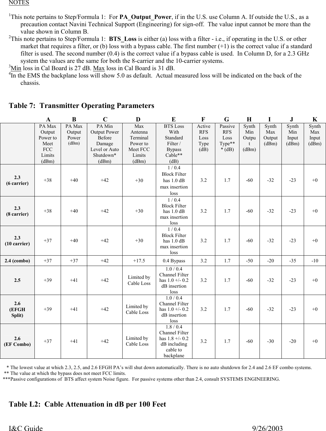
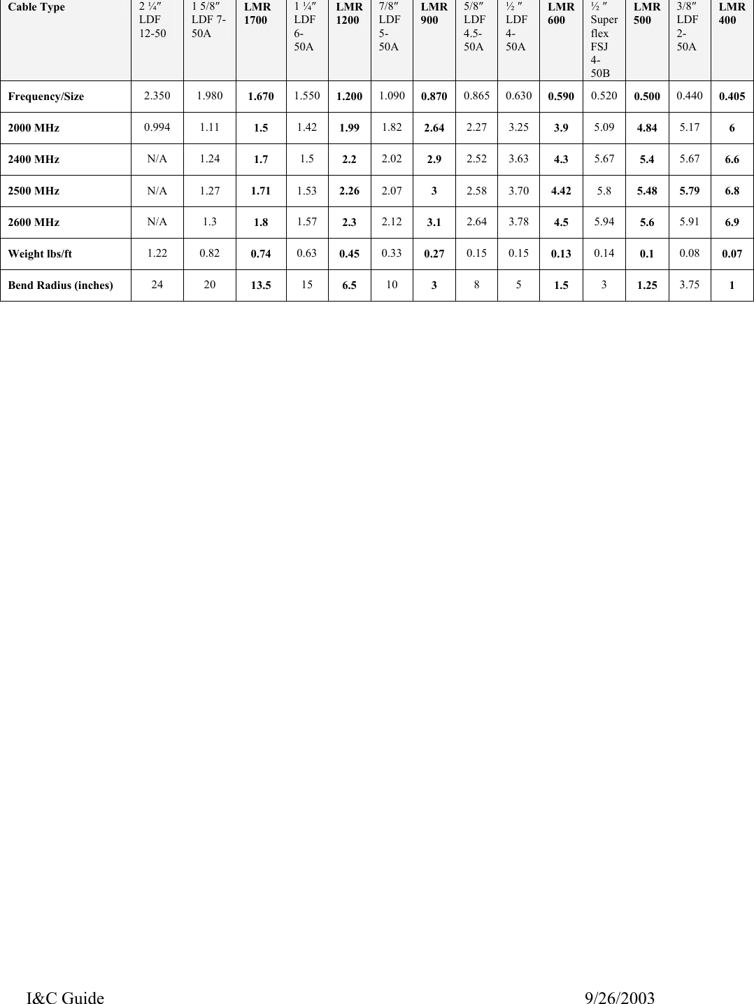
![I&C Guide 9/26/2003 Determine the maximum capable BTS output power to the antenna. = [(PA Output to Meet FCC) or (to Meet SNR)] – BTS Loss – RFS Loss – BTS Antenna Cable Loss* [Column A or B]1 – [Column E]2 – [Column F or G] – [Calculated* or Measured] • BTS Antenna Cable loss < 18 dB for ACTIVE RFS configurations • BTS Antenna Cable loss < 8 dB for PASSIVE RFS configurations Change the EMS settings accordingly. *Sub-procedure: Calculate BTS antenna cable loss, referring to Table 8. = [[Distance (length in ft) 100 ft] x Attenuation value/cable type] + 0.6 for 6 connectors/3 cables .. Determine the maximum BTS output power that can be calibrated. = Max Synth Input + Cal Cable Loss + Min Cal Board Loss3 + Backplane Loss4 [Column K] + [Calculated or Measured] + [Note 3] + [Default of 5.0 in EMS or Measured] Determine the actual** max BTS output power available to the antenna. = The lesser of the two values of Step/Formula 1 and Step/Formula 2 (aka, the “floor”) ** Actual is what you can calibrate the BTS at. Determine the minimum BTS output power that can be calibrated . = Min Synth Input + Cal Cable Loss + Max Cal Board Loss3 + Backplane Loss4 [Column J] + [Calculated or Measured] + [Note 3] + [Default of 5.0 in EMS or Measured] Determine the actual** maximum EIRP. = Step/Formula 3 + Antenna Gain. The antenna gain is affected by the type of antenna (omni, panel, 2.3, 2.4, etc.) and refers to the values in the RFS Configuration Script that accompanied the antenna from Manufacturing. **Actual is what you can calibrate the BTS at. Determine the minimum BTS RX input power that can be calibrated. = Min Synth Output - Cal Cable Loss - Min Cal Board Loss3 - Backplane Loss4 [Column H] - [Calculated or Measured] - [Note 3] - [Default of 5.0 in EMS or Measured] Determine the maximum BTS RX input power that can be calibrated. = Max Synth Output - Cal Cable Loss -Max Cal Board Loss3 - Backplane Loss4 [Column I] - [Calculated or Measured] - [Note 3] - [Default of 5.0 in EMS or Measured] AntennaCable SelectionStep/Formula 2 Step/Formula 4 Step/Formula 3 Step/Formula 5 Step/Formula 6 Step/Formula 7 Cal Cable SelectionStep/Formula 1 ..](https://usermanual.wiki/Cisco-Systems/WCS-BTS1.Manual-2/User-Guide-360666-Page-2.png)