Cisco Systems WCS-BTS1 Ripwave Base Station User Manual Appendix L Antenna Power Cable Selection
Cisco Systems, Inc Ripwave Base Station Appendix L Antenna Power Cable Selection
Contents
- 1. Manual 1
- 2. Manual 2
Manual 2

I&C Guide 9/26/2003
Appendix L: Antenna Power & Cable Selection
Overview
This section provides formulas and data that are necessary inputs for determining the right cable to be
measured, cut, and installed. There are 3 types of cables that are part of the Base Station installation: antenna
cables, calibration (cal) cable, and data/power cable.
The antenna cables are the eight cables that carry amplified RF signals. They run between the RF/PA cards
and the 8 antenna elements. The calibration (cal) cable is a single RF coaxial cable that provides an RF
feedback path for calibrating the system. It runs between the backplane of the digital shelf and the RFS. The
data/power cable may or may not be a separate cable from the cal cable. It is possible to use different types of
cable with different loss factors for the antenna cables and cal cable. The formulas presented in this section
call for either an antenna cable loss or a cal cable loss. Most applications deploy the same cable type for both
the antenna and cal cables.
To determine the type of cable and acceptable loss of that cable for a site, the operating transmit and receive
range must be known. This is commonly referred to as the maximum transmit output power and the receiver
sensitivity range. The operating transmit power and receive range should have been identified during the site
survey, or they may be based on regulatory compliance.
Determining the cable type and acceptable loss for a site are typically driven by two goals: (1) Which is the
least expensive cable; and (2) Which has the higher (normally) loss. Whether or not the goals are achieved is
determined by the output power. For example, the maximum transmit output power for a 2.6 Base Station
might be given as +30dBm, or 1 Watt, to the antenna. An example of receiver sensitivity for a 2.6 system
would be given as – 80 to –90 dBm.
In addition to cable power loss, other types of loss have to be factored - for example, the calibration board.
The calibration board is part of the RFS that samples the energy being transmitted from or received by the 8
antenna elements and combines that energy which is used when performing a calibration on the Base Station.
This loss, plus cable loss and other types of loss in the equipment are called out in the following procedure.
Procedure
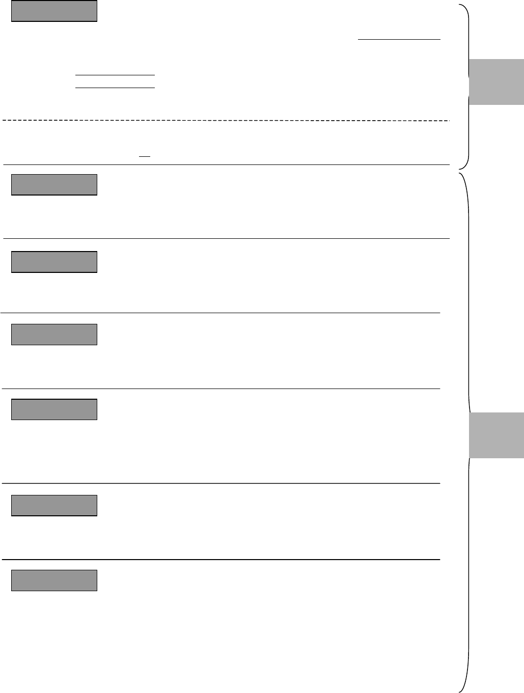
Read and follow the 7 steps/formulas below, in the order shown, to determine the resulting PA/RFS output
power and desired transmit and receive calibration range for the type of Base Station you will be installing.
Refer to Tables L1 and L2 to complete the steps. Table L1 provides Base Station operating parameters based
on system type (2.3, 2.4, etc.), as well as other variables. Table L2 provides cable attenuation data. Before you
begin, read through the steps/formulas, notes, and Table L1 in detail. Refer to the column letters at the top of
Table L1 to locate the appropriate values requested in some of the formulas. Note that step/formula 1 contains
a sub-procedure for determining antenna cable loss using Table L2.

I&C Guide 9/26/2003
Determine the maximum capable BTS output power to the antenna.
= [(PA Output to Meet FCC) or (to Meet SNR)] – BTS Loss – RFS Loss – BTS Antenna Cable Loss*
[Column A or B]1 – [Column E]2 – [Column F or G] – [Calculated* or Measured]
• BTS Antenna Cable loss < 18 dB for ACTIVE RFS configurations
• BTS Antenna Cable loss < 8 dB for PASSIVE RFS configurations
Change the EMS settings accordingly.
*Sub-procedure: Calculate BTS antenna cable loss, referring to Table 8.
= [[Distance (length in ft) 100 ft] x Attenuation value/cable type] + 0.6 for 6 connectors/3 cables
..
Determine the maximum BTS output power that can be calibrated.
= Max Synth Input + Cal Cable Loss + Min Cal Board Loss3 + Backplane Loss4
[Column K] + [Calculated or Measured] + [Note 3] + [Default of 5.0 in EMS or Measured]
Determine the actual** max BTS output power available to the antenna.
= The lesser of the two values of Step/Formula 1 and Step/Formula 2 (aka, the “floor”)
** Actual is what you can calibrate the BTS at.
Determine the minimum BTS output power that can be calibrated .
= Min Synth Input + Cal Cable Loss + Max Cal Board Loss3 + Backplane Loss4
[Column J] + [Calculated or Measured] + [Note 3] + [Default of 5.0 in EMS or Measured]
Determine the actual** maximum EIRP.
= Step/Formula 3 + Antenna Gain. The antenna gain is affected by the type of antenna (omni, panel, 2.3,
2.4, etc.) and refers to the values in the RFS Configuration Script that accompanied the antenna from
Manufacturing.
**Actual is what you can calibrate the BTS at.
Determine the minimum BTS RX input power that can be calibrated.
= Min Synth Output - Cal Cable Loss - Min Cal Board Loss3 - Backplane Loss4
[Column H] - [Calculated or Measured] - [Note 3] - [Default of 5.0 in EMS or Measured]
Determine the maximum BTS RX input power that can be calibrated.
= Max Synth Output - Cal Cable Loss -Max Cal Board Loss3 - Backplane Loss4
[Column I] - [Calculated or Measured] - [Note 3] - [Default of 5.0 in EMS or Measured]
Antenna
Cable
Selection
S
te
p
/Formula 2
S
te
p
/Formula 4
S
te
p
/Formula 3
S
te
p
/Formula 5
S
te
p
/Formula 6
S
te
p
/Formula 7
Cal
Cable
Selection
S
te
p
/Formula 1
..

I&C Guide 9/26/2003
NOTES
1This note pertains to Step/Formula 1: For PA_Output_Power, if in the U.S. use Column A. If outside the U.S., as a
precaution contact Navini Technical Support (Engineering) for sign-off. The value input cannot be more than the
value shown in Column B.
2This note pertains to Step/Formula 1: BTS_Loss is either (a) loss with a filter - i.e., if operating in the U.S. or other
market that requires a filter, or (b) loss with a bypass cable. The first number (+1) is the correct value if a standard
filter is used. The second number (0.4) is the correct value if a bypass cable is used. In Column D, for a 2.3 GHz
system the values are the same for both the 8-carrier and the 10-carrier systems.
3Min loss in Cal Board is 27 dB. Max loss in Cal Board is 31 dB.
4In the EMS the backplane loss will show 5.0 as default. Actual measured loss will be indicated on the back of the
chassis.
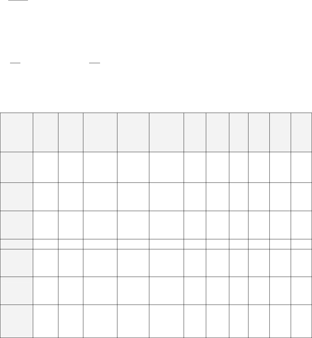
Table 7: Transmitter Operating Parameters
A B C D E F G H I J K
PA Max
Output
Power to
Meet
FCC
Limits
(dBm)
PA Max
Output
Power
(dBm)
PA Min
Output Power
Before
Damage
Level or Auto
Shutdown*
(dBm)
Max
Antenna
Terminal
Power to
Meet FCC
Limits
(dBm)
BTS Loss
With
Standard
Filter /
Bypass
Cable**
(dB)
Active
RFS
Loss
Type
(dB)
Passive
RFS
Loss
Type**
* (dB)
Synth
Min
Outpu
t
(dBm)
Synth
Max
Output
(dBm)
Synth
Min
Input
(dBm)
Synth
Max
Input
(dBm)
2.3
(6 carrier) +38 +40 +42 +30
1 / 0.4
Block Filter
has 1.0 dB
max insertion
loss
3.2 1.7 -60 -32 -23 +0
2.3
(8 carrier) +38 +40 +42 +30
1 / 0.4
Block Filter
has 1.0 dB
max insertion
loss
3.2 1.7 -60 -32 -23 +0
2.3
(10 carrier) +37 +40 +42 +30
1 / 0.4
Block Filter
has 1.0 dB
max insertion
loss
3.2 1.7 -60 -32 -23 +0
2.4 (combo) +37 +37 +42 +17.5 0.4 Bypass 3.2 1.7 -50 -20 -35 -10
2.5 +39 +41 +42 Limited by
Cable Loss
1.0 / 0.4
Channel Filter
has 1.0 +/- 0.2
dB insertion
loss
3.2 1.7 -60 -32 -23 +0
2.6
(EFGH
Split)
+39 +41 +42
Limited by
Cable Loss
1.0 / 0.4
Channel Filter
has 1.0 +/- 0.2
dB insertion
loss
3.2 1.7 -60 -32 -23 +0
2.6
(EF Combo) +37 +41 +42
Limited by
Cable Loss
1.8 / 0.4
Channel Filter
has 1.8 +/- 0.2
dB including
cable to
backplane
3.2 1.7 -60 -30 -20 +0
* The lowest value at which 2.3, 2.5, and 2.6 EFGH PA’s will shut down automatically. There is no auto shutdown for 2.4 and 2.6 EF combo systems.
** The value at which the bypass does not meet FCC limits.
***Passive configurations of BTS affect system Noise figure. For passive systems other than 2.4, consult SYSTEMS ENGINEERING.
Table L2: Cable Attenuation in dB per 100 Feet

I&C Guide 9/26/2003
Cable Type 2 ¼″
LDF
12-50
1 5/8″
LDF 7-
50A
LMR
1700
1 ¼″
LDF
6-
50A
LMR
1200
7/8″
LDF
5-
50A
LMR
900
5/8″
LDF
4.5-
50A
½ ″
LDF
4-
50A
LMR
600
½ ″
Super
flex
FSJ
4-
50B
LMR
500
3/8″
LDF
2-
50A
LMR
400
Frequency/Size 2.350 1.980 1.670 1.550 1.200 1.090 0.870 0.865 0.630 0.590 0.520 0.500 0.440 0.405
2000 MHz 0.994 1.11 1.5 1.42 1.99 1.82 2.64 2.27 3.25 3.9 5.09 4.84 5.17 6
2400 MHz N/A 1.24 1.7 1.5 2.2 2.02 2.9 2.52 3.63 4.3 5.67 5.4 5.67 6.6
2500 MHz N/A 1.27
1.71 1.53 2.26 2.07 3 2.58 3.70 4.42 5.8 5.48 5.79 6.8
2600 MHz N/A 1.3 1.8 1.57 2.3 2.12 3.1 2.64 3.78 4.5 5.94 5.6 5.91 6.9
Weight lbs/ft 1.22 0.82 0.74 0.63 0.45 0.33 0.27 0.15 0.15 0.13 0.14 0.1 0.08 0.07
Bend Radius (inches) 24 20
13.5 15 6.5 10 3 8 5
1.5 3 1.25 3.75 1