Cisco Systems XSCLCR15 4.9 GHz WMIC Mini PCI Module User Manual MRhBookb
Cisco Systems Inc 4.9 GHz WMIC Mini PCI Module MRhBookb
Contents
OEM User Manual 1

Final Draft - Cisco Confidential
Corporate Headquarters
Cisco Systems, Inc.
170 West Tasman Drive
San Jose, CA 95134-1706
USA
http://www.cisco.com
Tel: 408 526-4000
800 553-NETS (6387)
Fax: 408 526-4100
Cisco 3200 Series Mobile Access Router
Hardware Reference
July 14, 2005
Customer Order Number: 85-4201-06
Text Part Number: OL-5816-04

Final Draft - Cisco Confidential
THE SPECIFICATIONS AND INFORMATION REGARDING THE PRODUCTS IN THIS MANUAL ARE SUBJECT TO CHANGE WITHOUT NOTICE. ALL
STATEMENTS, INFORMATION, AND RECOMMENDATIONS IN THIS MANUAL ARE BELIEVED TO BE ACCURATE BUT ARE PRESENTED WITHOUT
WARRANTY OF ANY KIND, EXPRESS OR IMPLIED. USERS MUST TAKE FULL RESPONSIBILITY FOR THEIR APPLICATION OF ANY PRODUCTS.
THE SOFTWARE LICENSE AND LIMITED WARRANTY FOR THE ACCOMPANYING PRODUCT ARE SET FORTH IN THE INFORMATION PACKET THAT
SHIPPED WITH THE PRODUCT AND ARE INCORPORATED HEREIN BY THIS REFERENCE. IF YOU ARE UNABLE TO LOCATE THE SOFTWARE LICENSE
OR LIMITED WARRANTY, CONTACT YOUR CISCO REPRESENTATIVE FOR A COPY.
The Cisco implementation of TCP header compression is an adaptation of a program developed by the University of California, Berkeley (UCB) as part of UCB’s public
domain version of the UNIX operating system. All rights reserved. Copyright © 1981, Regents of the University of California.
NOTWITHSTANDING ANY OTHER WARRANTY HEREIN, ALL DOCUMENT FILES AND SOFTWARE OF THESE SUPPLIERS ARE PROVIDED “AS IS” WITH
ALL FAULTS. CISCO AND THE ABOVE-NAMED SUPPLIERS DISCLAIM ALL WARRANTIES, EXPRESSED OR IMPLIED, INCLUDING, WITHOUT
LIMITATION, THOSE OF MERCHANTABILITY, FITNESS FOR A PARTICULAR PURPOSE AND NONINFRINGEMENT OR ARISING FROM A COURSE OF
DEALING, USAGE, OR TRADE PRACTICE.
IN NO EVENT SHALL CISCO OR ITS SUPPLIERS BE LIABLE FOR ANY INDIRECT, SPECIAL, CONSEQUENTIAL, OR INCIDENTAL DAMAGES, INCLUDING,
WITHOUT LIMITATION, LOST PROFITS OR LOSS OR DAMAGE TO DATA ARISING OUT OF THE USE OR INABILITY TO USE THIS MANUAL, EVEN IF CISCO
OR ITS SUPPLIERS HAVE BEEN ADVISED OF THE POSSIBILITY OF SUCH DAMAGES.
Cisco 3200 Series Mobile Access Router Hardware Reference
Copyright © 2005, Cisco Systems, Inc.
All rights reserved.
C
CIP, CCSP, the Cisco Arrow logo, the Cisco Powered Network mark, Cisco Unity, Follow Me Browsing, FormShare, and StackWise are trademarks of Cisco Systems, Inc.;
C
hanging the Way We Work, Live, Play, and Learn, and iQuick Study are service marks of Cisco Systems, Inc.; and Aironet, ASIST, BPX, Catalyst, CCDA, CCDP, CCIE, CCNA,
C
CNP, Cisco, the Cisco Certified Internetwork Expert logo, Cisco IOS, the Cisco IOS logo, Cisco Press, Cisco Systems, Cisco Systems Capital, the Cisco Systems logo,
E
mpowering the Internet Generation, Enterprise/Solver, EtherChannel, EtherSwitch, Fast Step, GigaStack, Internet Quotient, IOS, IP/TV, iQ Expertise, the iQ logo, iQ Net
R
eadiness Scorecard, LightStream, MGX, MICA, the Networkers logo, Networking Academy, Network Registrar, Packet, PIX, Post-Routing, Pre-Routing, RateMUX, Registrar,
S
criptShare, SlideCast, SMARTnet, StrataView Plus, Stratm, SwitchProbe, TeleRouter, The Fastest Way to Increase Your Internet Quotient, TransPath, and VCO are registered
t
rademarks of Cisco Systems, Inc. and/or its affiliates in the United States and certain other countries.
A
ll other trademarks mentioned in this document or Website are the property of their respective owners. The use of the word partner does not imply a partnership relationship
b
etween Cisco and any other company. (0401R)

iii
Cisco 3200 Series Mobile Access Router Hardware Reference
OL-5816-04
CONTENTS
Introduction to the Cisco 3200 Series Mobile Access Router Cards i
Audience and Scope ii
Related Documentation ii
Obtaining Documentation iv
Cisco.com iv
Ordering Documentation iv
Documentation Feedback v
Tools and Web Sites v
Obtaining Additional Publications and Information vi
Cisco 3200 Documentation CD vii
System Requirements for the CD vii
Printing Documents from the CD viii
Conventions viii
Obtaining Technical Assistance xii
Cisco Technical Support Website xii
Submitting a Service Request xiii
Definitions of Service Request Severity xiii
CHAPTER
1Mobile Access Router Card (MARC) 1-1
MARC Component Systems 1-2
MARC Router Signals 1-2
10/100 Fast Ethernet Signals on the MARC 1-3
Console, Auxiliary, LED Signals, and Power 1-4
MARC Power Requirements 1-6
CHAPTER
2Fast Ethernet Switch Mobile Interface Card (FESMIC) 2-1
Auto-Negotiation and Auto-MDI/MDIX 2-2
MAC Address Allocation 2-2
FESMIC Component Systems 2-3
Signals for the FESMIC 2-4
10/100 Fast Ethernet Signals on the FESMIC 2-4
FESMIC LED Signals 2-5
FESMIC Rotary Switch Positions 2-7

Contents
iv
Cisco 3200 Series Mobile Access Router Hardware Reference
OL-5816-04
CHAPTER
3Serial Mobile Interface Card (SMIC) 3-1
SMIC Component Systems 3-2
Signals for the SMIC 3-3
Serial Cable Length 3-3
SMIC LED Signals 3-4
4-Port SMIC Rotary Switch Positions 3-4
CHAPTER
4Wireless Mobile Interface Card (WMIC) 4-1
WMIC Component Systems 4-1
Signals for the WMIC 4-2
10/100 Fast Ethernet Signals on the WMIC 4-3
WMIC Multifunction Header Signals 4-4
LED Behavior 4-5
Antenna Connector 4-6
Key Features 4-6
2.4-GHz (802.11b/g) Features 4-6
4.9-GHz (US Only, Public Safety) Features 4-7
Throughput 4-8
Modulation 4-8
Receive Sensitivity 4-8
2.4-GHz (802.11b/g) WMIC and the 4.9-GHz (US Only, Public Safety) Features 4-9
MAC Address Allocation 4-10
Power Requirements 4-10
Related Documentation 4-10

i
Cisco 3200 Series Mobile Access Router Hardware Guide
OL-5816-04
Introduction to the Cisco 3200 Series
Mobile Access Router Cards
The Cisco 3200 Series Mobile Access Routers include a combination of mobile
interface cards. The following cards are available from Cisco:
•Mobile Access Router Card (MARC)
•Fast Ethernet Switch Mobile Interface Cards (FESMICs)
•Serial Mobile Interface Cards (SMICs)
•Wireless Mobile Interface Cards (WMICs)
A completed router includes a third-party power source, cables, and an enclosure,
that are assembled and installed by your system integrator. This document
describes the cards provided by Cisco Systems, Inc. used to assemble
Cisco 3200 Series Mobile Access Routers. For information regarding the specific
hardware configuration of your router, contact your vendor.
The following chapters provide the information that you need to understand the
physical components of a completed Cisco 3200 Series Mobile Access Router. It
is not intended as assembly or repair instructions.
Chapter 1, “Mobile Access Router Card (MARC),” describes the Mobile Access
Router Card (MARC) layout, ports, and buses.
Chapter 2, “Fast Ethernet Switch Mobile Interface Card (FESMIC),” describes
the Fast Ethernet Switch Mobile Interface Cards (FESMICs) layout, ports, and
buses.

ii
Cisco 3200 Series Mobile Access Router Hardware Guide
OL-5816-04
Chapter 3, “Serial Mobile Interface Card (SMIC),” describes the Serial Mobile
Interface Cards (SMICs) layout, ports, and buses.
Chapter 4, “Wireless Mobile Interface Card (WMIC),” describes the Wireless
Mobile Interface Cards (WMICs) layout, ports, and buses.
Audience and Scope
The audience for this document is the system administrator (SA), system
integrator (SI), and system engineer (SE). They are experts, with networking
industry training and experience. We assume that users are familiar with the
terminology and concepts of the PC-104, IOS, and Mobile IP networking.
The SA, SI, or SE uses this document to understand how the router hardware is
connected to peripheral devices and to perform minor troubleshooting on the
cards. Although they might not be specifically identified as SAs, SIs, or SEs, all
users of this documentation are assumed to have comparable skills and
knowledge.
Related Documentation
You can access these documents on the Documentation page on Cisco Connection
Online (CCO) at www.cisco.com. The following documentation is available at the
http://www.cisco.com/en/US/products/hw/routers/ps272/tsd_products_support_s
eries_home.html
URL:
•Release Notes for the Cisco 3200 Series Mobile Access Routers
(78-13975)—Provides information on accessing documentation and
technical assistance for the Cisco 3200 Series Mobile Access Router.
•Cisco 3200 Series Wireless MIC Software Configuration Guide1
(OL-7734)—This document. It provides example procedures for using the
IOS commands to configure Wireless Mobile Interface Cards (WMICs).
•Configuration Guide for the Cisco 3200 Series Mobile Access
Router1—Example procedures for using the IOS commands to configure the
Mobile Access Router Card (MARC) in Cisco 3200 Series routers.

iii
Cisco 3200 Series Mobile Access Router Hardware Guide
OL-5816-04
•Cisco 3200 Series Mobile Access Router Hardware Reference1
(OL-5816)—descriptions of the Cisco MIC I/O cards found in Cisco 3200
Series routers.
•Cisco 3200 Series Mobile Access Router Reference Sell Document1
(OL-3880)—An overview of the reference sell program and components for
the Cisco 3200 Series router.
•Regulatory Compliance and Safety Information for the Cisco 3200 Mobile
Access Router (78-16930)—Regulatory compliance and safety information.
1. Also available on the platform-specific CD-ROM.
The Release Notes for the Cisco 3250 Mobile Router lists the enhancements to
and caveats for Cisco IOS releases as they relate to the Cisco 3200 Series router
can be found at:
http://www.cisco.com/en/US/products/sw/iosswrel/products_ios_cisco_ios_soft
ware_releases.html or
http://www.cisco.com/en/US/products/sw/iosswrel/ps5012/ps4629/index.html
For information about using Cisco IOS software to configure SNMP, refer to the
following documents:
•The “Configuring SNMP Support” chapter of the Cisco IOS Configuration
Fundamentals Configuration Guide, Release 12.2
•The “SNMP Commands” chapter of the Cisco IOS Configuration
Fundamentals Command Reference, Release 12.2
For information about using Cisco IOS software to configure SNMP MIB
features, refer to the appropriate documentation for your network management
system.
For information on configuring Mobile IP using Cisco IOS software, refer to the
following documents:
•The “Configuring Mobile IP” chapter of the Cisco IOS IP Configuration
Guide, Release 12.2
•The “Mobile IP Commands” chapter of the Cisco IOS IP Command
Reference, Volume 1 of 3: Addressing and Services, Release 12.2
Related documents from the Cisco TAC Web pages include:
•Antenna Cabling
http://www.cisco.com/warp/public/102/wlan/antcable.html

iv
Cisco 3200 Series Mobile Access Router Hardware Guide
OL-5816-04
Obtaining Documentation
Cisco documentation and additional literature are available on Cisco.com. Cisco
also provides several ways to obtain technical assistance and other technical
resources. These sections explain how to obtain technical information from Cisco
Systems.
Cisco.com
You can access the Cisco website at this URL:
http://www.cisco.com
You can access international Cisco websites at this URL:
http://www.cisco.com/public/countries_languages.shtml
Ordering Documentation
You can order Cisco documentation in these ways:
•Registered Cisco.com users (Cisco direct customers) can order Cisco product
documentation from the Ordering tool:
http://www.cisco.com/en/US/partner/ordering/index.shtml
•Nonregistered Cisco.com users can order documentation through a local
account representative by calling Cisco Systems Corporate Headquarters
(California, USA) at 408 526-7208 or, elsewhere in North America, by
calling 1 800 553-NETS (6387).

v
Cisco 3200 Series Mobile Access Router Hardware Guide
OL-5816-04
Documentation Feedback
You can send comments about technical documentation to bug-doc@cisco.com.
You can submit comments by using the response card (if present) behind the front
cover of your document or by writing to the following address:
Cisco Systems
Attn: Customer Document Ordering
170 West Tasman Drive
San Jose, CA 95134-9883
We appreciate your comments.
Tools and Web Sites
If you are registered Cisco Direct Customer, you can access the following web
sites:
IOS Command Lookup—A search engine dedicated to finding information on
Cisco IOS commands in the Cisco IOS Command Reference, Cisco IOS
Configuration Guide, Catalyst Command Reference, and PIX Firewall Command
Reference.
http://www.cisco.com/cgi-bin/Support/Cmdlookup/home.pl
Bug Toolkit—Searches for known bugs based on software version, feature set and
keywords. The resulting matrix shows when each bug was integrated, or fixed if
applicable.
http://www.cisco.com/cgi-bin/Support/Bugtool/launch_bugtool.pl
Feature Navigator—Locates the Cisco IOS Software release based on the features
you want to run on your network.
http://tools.cisco.com/ITDIT/CFN/jsp/index.jsp
Obtain information on compatibility between hardware products and software
releases at the following public URL:
http://tools.cisco.com/Support/Fusion/FusionHome.do

vi
Cisco 3200 Series Mobile Access Router Hardware Guide
OL-5816-04
Obtaining Additional Publications and Information
Information about Cisco products, technologies, and network solutions is
available from various online and printed sources.
•Cisco Marketplace provides a variety of Cisco books, reference guides, and
logo merchandise. Visit Cisco Marketplace, the company store, at this URL:
http://www.cisco.com/go/marketplace/
•The Cisco Product Catalog describes the networking products offered by
Cisco Systems, as well as ordering and customer support services. Access the
Cisco Product Catalog at this URL:
http://cisco.com/univercd/cc/td/doc/pcat/
•Cisco Press publishes a wide range of general networking, training and
certification titles. Both new and experienced users will benefit from these
publications. For current Cisco Press titles and other information, go to Cisco
Press at this URL:
http://www.ciscopress.com
•Packet magazine is the Cisco Systems technical user magazine for
maximizing Internet and networking investments. Each quarter, Packet
delivers coverage of the latest industry trends, technology breakthroughs, and
Cisco products and solutions, as well as network deployment and
troubleshooting tips, configuration examples, customer case studies,
certification and training information, and links to scores of in-depth online
resources. You can access Packet magazine at this URL:
http://www.cisco.com/packet
•iQ Magazine is the quarterly publication from Cisco Systems designed to
help growing companies learn how they can use technology to increase
revenue, streamline their business, and expand services. The publication
identifies the challenges facing these companies and the technologies to help
solve them, using real-world case studies and business strategies to help
readers make sound technology investment decisions. You can access iQ
Magazine at this URL:
http://www.cisco.com/go/iqmagazine

vii
Cisco 3200 Series Mobile Access Router Hardware Guide
OL-5816-04
•Internet Protocol Journal is a quarterly journal published by Cisco Systems
for engineering professionals involved in designing, developing, and
operating public and private internets and intranets. You can access the
Internet Protocol Journal at this URL:
http://www.cisco.com/ipj
•World-class networking training is available from Cisco. You can view
current offerings at this URL:
http://www.cisco.com/en/US/learning/index.html
Cisco 3200 Documentation CD
The Cisco 3200 Series Router Documentation CD contains the technical
publications for the Cisco 3200 Series Mobile Access Router. To view the
documentation requires Acrobat Reader 4.0 or higher.
After the CD is inserted in the CD ROM drive and recognized by your PC, do the
following:
Step 1 Access the root directory CD drive.
Step 2 Double click the StartHere.htm file.
System Requirements for the CD
Processor Pentium 150 MHz or faster recommended
PC Operating System Microsoft Windows 95
Microsoft Windows 98
Microsoft Windows ME
Microsoft Windows XP
Microsoft Windows NT 4.0
Microsoft Windows 2000
Memory 64-MB DRAM

viii
Cisco 3200 Series Mobile Access Router Hardware Guide
OL-5816-04
Printing Documents from the CD
To print a document:
Step 1 Display the document in Acrobat.
Step 2 Click the Printer icon on the Acrobat toolbar.
The Windows Print Dialog box appears.
Step 3 Select your default printer, and click OK.
Conventions
This publication uses these conventions to convey instructions and information:
Command descriptions use these conventions:
•Commands and keywords are in boldface text.
•Arguments for which you supply values are in italic.
•Square brackets ([ ]) mean optional elements.
•Braces ({ }) group required choices, and vertical bars ( | ) separate the
alternative elements.
•Braces and vertical bars within square brackets ([{ | }]) mean a required
choice within an optional element.
Drives 4x CD-ROM drive
Monitor Color monitor capable of 800 x 600 pixel
resolution
Software Adobe Acrobat Reader 4.0 or later
Processor Pentium 150 MHz or faster recommended

ix
Cisco 3200 Series Mobile Access Router Hardware Guide
OL-5816-04
Interactive examples use these conventions:
•Terminal sessions and system displays are in screen font.
•Information you enter is in boldface screen font.
•Nonprinting characters, such as passwords or tabs, are in angle brackets (< >).
Notes, cautions, and timesavers use these conventions and symbols:
Tip Means the following will help you solve a problem. The tips information might
not be troubleshooting or even an action, but could be useful information.
Note Means reader take note. Notes contain helpful suggestions or references to
materials not contained in this manual.
Caution Means reader be careful. In this situation, you might do something that could
result equipment damage or loss of data.
Warning
This warning symbol means danger. You are in a situation that could cause
bodily injury. Before you work on any equipment, be aware of the hazards
involved with electrical circuitry and be familiar with standard practices for
preventing accidents. (To see translations of the warnings that appear in this
publication, refer to the appendix “Translated Safety Warnings.”)
Waarschuwing
Dit waarschuwingssymbool betekent gevaar. U verkeert in een situatie die
lichamelijk letsel kan veroorzaken. Voordat u aan enige apparatuur gaat
werken, dient u zich bewust te zijn van de bij elektrische schakelingen
betrokken risico’s en dient u op de hoogte te zijn van standaard maatregelen
om ongelukken te voorkomen. (Voor vertalingen van de waarschuwingen die
in deze publicatie verschijnen, kunt u het aanhangsel “Translated Safety
Warnings” (Vertalingen van veiligheidsvoorschriften) raadplegen.)

x
Cisco 3200 Series Mobile Access Router Hardware Guide
OL-5816-04
Varoitus
Tämä varoitusmerkki merkitsee vaaraa. Olet tilanteessa, joka voi johtaa
ruumiinvammaan. Ennen kuin työskentelet minkään laitteiston parissa, ota
selvää sähkökytkentöihin liittyvistä vaaroista ja tavanomaisista
onnettomuuksien ehkäisykeinoista. (Tässä julkaisussa esiintyvien
varoitusten käännökset löydät liitteestä "Translated Safety Warnings"
(käännetyt turvallisuutta koskevat varoitukset).)
Attention
Ce symbole d’avertissement indique un danger. Vous vous trouvez dans une
situation pouvant entraîner des blessures. Avant d’accéder à cet équipement,
soyez conscient des dangers posés par les circuits électriques et
familiarisez-vous avec les procédures courantes de prévention des accidents.
Pour obtenir les traductions des mises en garde figurant dans cette
publication, veuillez consulter l’annexe intitulée « Translated Safety
Warnings » (Traduction des avis de sécurité).
Warnung
Dieses Warnsymbol bedeutet Gefahr. Sie befinden sich in einer Situation, die
zu einer Körperverletzung führen könnte. Bevor Sie mit der Arbeit an
irgendeinem Gerät beginnen, seien Sie sich der mit elektrischen
Stromkreisen verbundenen Gefahren und der Standardpraktiken zur
Vermeidung von Unfällen bewußt. (Übersetzungen der in dieser
Veröffentlichung enthaltenen Warnhinweise finden Sie im Anhang mit dem
Titel “Translated Safety Warnings” (Übersetzung der Warnhinweise).)
Avvertenza
Questo simbolo di avvertenza indica un pericolo. Si è in una situazione che
può causare infortuni. Prima di lavorare su qualsiasi apparecchiatura,
occorre conoscere i pericoli relativi ai circuiti elettrici ed essere al corrente
delle pratiche standard per la prevenzione di incidenti. La traduzione delle
avvertenze riportate in questa pubblicazione si trova nell’appendice,
“Translated Safety Warnings” (Traduzione delle avvertenze di sicurezza).
Advarsel
Dette varselsymbolet betyr fare. Du befinner deg i en situasjon som kan føre
til personskade. Før du utfører arbeid på utstyr, må du være oppmerksom på de
faremomentene som elektriske kretser innebærer, samt gjøre deg kjent med
vanlig praksis når det gjelder å unngå ulykker. (Hvis du vil se oversettelser av
de advarslene som finnes i denne publikasjonen, kan du se i vedlegget
"Translated Safety Warnings" [Oversatte sikkerhetsadvarsler].)

xi
Cisco 3200 Series Mobile Access Router Hardware Guide
OL-5816-04
Aviso
Este símbolo de aviso indica perigo. Encontra-se numa situação que lhe
poderá causar danos fisicos. Antes de começar a trabalhar com qualquer
equipamento, familiarize-se com os perigos relacionados com circuitos
eléctricos, e com quaisquer práticas comuns que possam prevenir possíveis
acidentes. (Para ver as traduções dos avisos que constam desta publicação,
consulte o apêndice “Translated Safety Warnings” - “Traduções dos Avisos de
Segurança”).
¡Advertencia!
Este símbolo de aviso significa peligro. Existe riesgo para su integridad física.
Antes de manipular cualquier equipo, considerar los riesgos que entraña la
corriente eléctrica y familiarizarse con los procedimientos estándar de
prevención de accidentes. (Para ver traducciones de las advertencias que
aparecen en esta publicación, consultar el apéndice titulado “Translated
Safety Warnings.”)
Varning!
Denna varningssymbol signalerar fara. Du befinner dig i en situation som kan
leda till personskada. Innan du utför arbete på någon utrustning måste du vara
medveten om farorna med elkretsar och känna till vanligt förfarande för att
förebygga skador. (Se förklaringar av de varningar som förekommer i denna
publikation i appendix "Translated Safety Warnings" [Översatta
säkerhetsvarningar].)

xii
Cisco 3200 Series Mobile Access Router Hardware Guide
OL-5816-04
Obtaining Technical Assistance
For all customers, partners, resellers, and distributors who hold valid Cisco
service contracts, Cisco Technical Support provides 24-hour-a-day,
award-winning technical assistance.
The Cisco Technical Support Website on Cisco.com features extensive online
support resources. In addition, Cisco Technical Assistance Center (TAC)
engineers provide telephone support. If you do not hold a valid Cisco service
contract, contact your reseller.
Cisco Technical Support Website
The Cisco Technical Support Website provides online documents and tools for
troubleshooting and resolving technical issues with Cisco products and
technologies. The website is available 24 hours a day, 365 days a year, at this
URL:
http://www.cisco.com/techsupport
Access to all tools on the Cisco Technical Support Website requires a Cisco.com
user ID and password. If you have a valid service contract but do not have a user
ID or password, you can register at this URL:
http://tools.cisco.com/RPF/register/register.do
Note Use the Cisco Product Identification (CPI) tool to locate your product serial
number before submitting a web or phone request for service. You can access the
CPI tool from the Cisco Technical Support Website by clicking the To ols &
Resources link under Documentation & Tools. Choose Cisco Product
Identification Tool from the Alphabetical Index drop-down list, or click the
Cisco Product Identification Tool link under Alerts & RMAs. The CPI tool
offers three search options: by product ID or model name; by tree view; or for
certain products, by copying and pasting show command output. Search results
show an illustration of your product with the serial number label location
highlighted. Locate the serial number label on your product and record the
information before placing a service call.

xiii
Cisco 3200 Series Mobile Access Router Hardware Guide
OL-5816-04
Submitting a Service Request
Using the online TAC Service Request Tool is the fastest way to open S3 and S4
service requests. (S3 and S4 service requests are those in which your network is
minimally impaired or for which you require product information.) After you
describe your situation, the TAC Service Request Tool provides recommended
solutions. If your issue is not resolved using the recommended resources, your
service request is assigned to a Cisco TAC engineer. The TAC Service Request
Tool is located at this URL:
http://www.cisco.com/techsupport/servicerequest
For S1 or S2 service requests or if you do not have Internet access, contact the
Cisco TAC by telephone. (S1 or S2 service requests are those in which your
production network is down or severely degraded.) Cisco TAC engineers are
assigned immediately to S1 and S2 service requests to help keep your business
operations running smoothly.
To open a service request by telephone, use one of the following numbers:
Asia-Pacific: +61 2 8446 7411 (Australia: 1 800 805 227)
EMEA: +32 2 704 55 55
USA: 1 800 553-2447
For a complete list of Cisco TAC contacts, go to this URL:
http://www.cisco.com/techsupport/contacts
Definitions of Service Request Severity
To ensure that all service requests are reported in a standard format, Cisco has
established severity definitions.
Severity 1 (S1)—Your network is “down,” or there is a critical impact to your
business operations. You and Cisco will commit all necessary resources around
the clock to resolve the situation.
Severity 2 (S2)—Operation of an existing network is severely degraded, or
significant aspects of your business operation are negatively affected by
inadequate performance of Cisco products. You and Cisco will commit full-time
resources during normal business hours to resolve the situation.

xiv
Cisco 3200 Series Mobile Access Router Hardware Guide
OL-5816-04
Severity 3 (S3)—Operational performance of your network is impaired, but most
business operations remain functional. You and Cisco will commit resources
during normal business hours to restore service to satisfactory levels.
Severity 4 (S4)—You require information or assistance with Cisco product
capabilities, installation, or configuration. There is little or no effect on your
business operations.

CHAPTER
1-1
Cisco 3200 Series Mobile Access Router Hardware Guide
OL-5816-04
1
Mobile Access Router Card (MARC)
The Mobile Access Router Card (MARC) is one component of the Cisco 3200 Series Mobile Access
Router. It includes the host processor, memory, and headers for the 10/100 Fast Ethernet, console, and
auxiliary signals for the router. Additional components provide power and link interfaces to the MARC.
For example, the 4-port Serial Mobile Interface Card provides up to 4 smart serial interfaces. The exact
configuration of your router will vary, depending on how it was configured by your vendor.
Note This section provides basic information regarding the MARC hardware for the purpose of performing
simple troubleshooting, such as reconnecting a loose cable. To solve more difficult problems, please
contact your vendor.
The key features of the MARC include the following:
•MPC8250 processor running 210-MHz at the CPU core, 150-MHz at the CPM core, and 60-MHz
on the Motorola 60x bus
•32 MB of Flash memory
•128 MB synchronous DRAM
•10/100 Fast Ethernet, full-duplex connection with auto negotiation
•Console connection with hardware/software flow control
•Asynchronous, RS-232 serial connection with a 5 V auxiliary power supply for Global Positioning
System (GPS) and auxiliary (AUX) devices
•A 32-bit PCI bus, version 2.1 running at 25-MHz
•Supports zeroization when this featured is configured on the router.
Caution Zeroization is a feature that erases all potentially sensitive information from the router. Zeroization is
configured through the CLI and activated through an actuator that must be attached to the AUX port,
such as a push button. Zeroization is disabled by default on the Cisco 3200 Series router.
When Zeroization is not configured on the router, the AUX port functions as a modem port or a terminal
port. When declassification is enabled through the CLI, we recommend that you do not use the AUX port
for any other function than declassification. This is because there is no way for the router to reliably
determine if a device attached to the AUX port is an actuator; therefore, any device attached to the AUX
port could potentially trigger declassification.
1-2
Cisco 3200 Series Mobile Access Router Hardware Guide
OL-5816-04
Chapter 1 Mobile Access Router Card (MARC)
MARC Component Systems
MARC Component Systems
The industry-standard architecture (ISA) buses and peripheral component interconnect (PCI) buses on
the Cisco 3200 Series Mobile Access Router cards provide power to the components on the cards. Both
buses comply with the PC/104-Plus standard. The ISA bus allows PC/104-Plus ISA signals to pass
through the card bus, but the Cisco cards do not use any of the signals.
The PCI bus signals allow the Cisco cards to communicate. Non-Cisco cards cannot communicate with
the Cisco 3200 Series Mobile Access Router cards over the PCI bus.
Caution If you add non-Cisco cards that generates signals on the PCI bus, the router might shut down. Please do
not add non-Cisco cards that generate signals on the PCI bus.
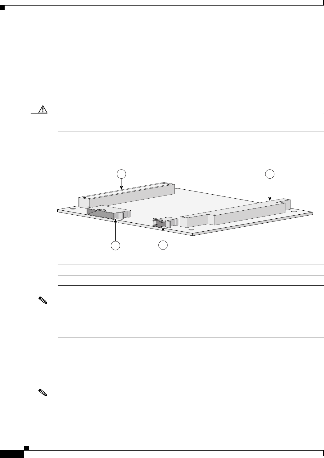
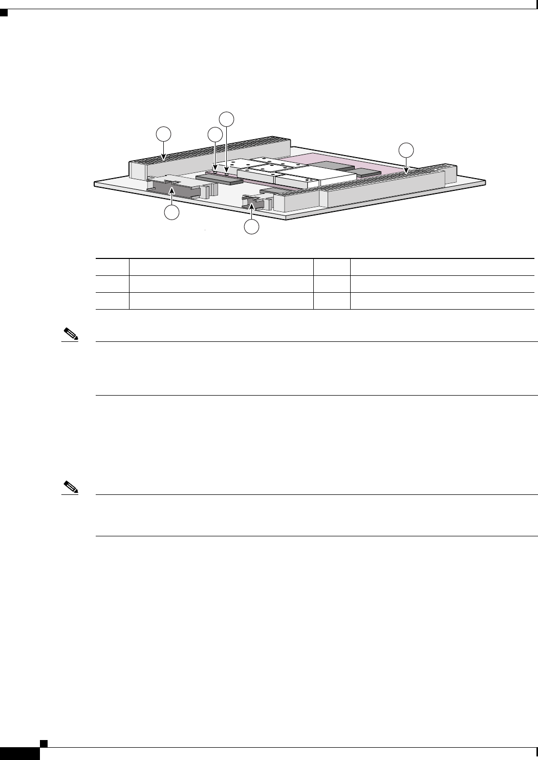
Figure 1-1 shows the MARC header and bus locations.
Figure 1-1 MARC Header and Bus Locations
Note The PC/104-Plus standard requires that the PCI Bus and the ISA bus utilize keying features in the
standard stacking headers to guarantee proper module installation. On the PCI bus, pin D30 is removed
and the D30 opening plugged. On the ISA bus, pin C19 and B10 are removed, and the C19 and B10
openings are plugged.
MARC Router Signals
Cisco 3200 Series router cards do not support any ISA bus signals. The PCI bus connector supports
communication between Cisco 3200 Series Mobile Access Router cards.
Note Non-Cisco MIC cards cannot use PCI signals. The use of PCI signals by non-Cisco cards causes
unpredictable results. You cannot add 3rd-party devices that might attempt to communicate with the
SMIC through the ISA or PCI bus.
1PCI Bus 2ISA Bus
3Ethernet Header 4Multifunction Header
74518
1 2
43
1-3
Cisco 3200 Series Mobile Access Router Hardware Guide
OL-5816-04
Chapter 1 Mobile Access Router Card (MARC)
MARC Component Systems
The signals are delivered through the shared, 34-pin multifunction header and the 10-pin Ethernet
header. LED signals and 5 V of power are also provided through the shared, 34-pin multifunction header.
10/100 Fast Ethernet Signals on the MARC
There is one fixed 10/100 Fast Ethernet port on the MARC. A Cisco router identifies a 10/100 Fast
Ethernet interface address by its slot number and port number, in the format slot/port. The slot/port
address of a Fast Ethernet interface on the MARC is 0/0.
The 10/100 Fast Ethernet port signals are in compliance with IEEE 802.3. They are provided through the
10-pin Ethernet header, which supports the following:
•Auto-negotiation and parallel detection MII interface with extended register capability for
10/100BASE-TX connection
•Full-duplex and half-duplex modes
•3.3V operation low power consumption (300 mW typical)
•Low-power sleep mode
•10BASE-T and 100BASE-TX using a single Ethernet connection
•Robust baseline wander correction performance
•100BASE-FX fiber optic capabilities
•Standard carrier signal multiple access collision detect (CSMA/CD) or full-duplex operation
•Integrated, programmable LED drivers
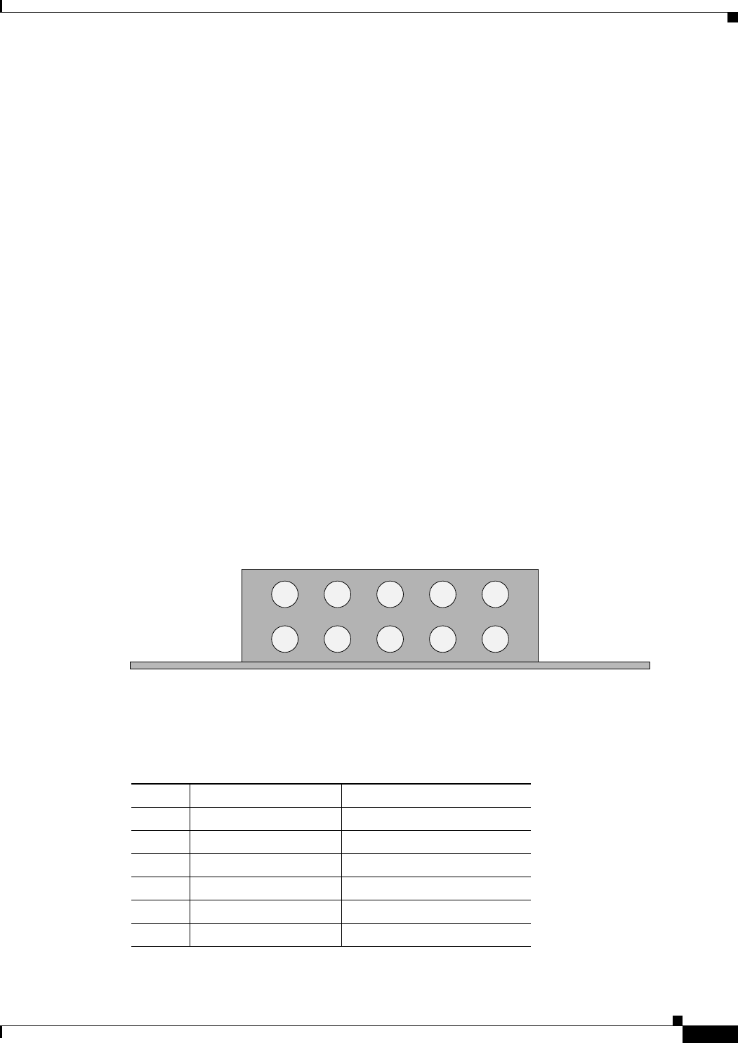
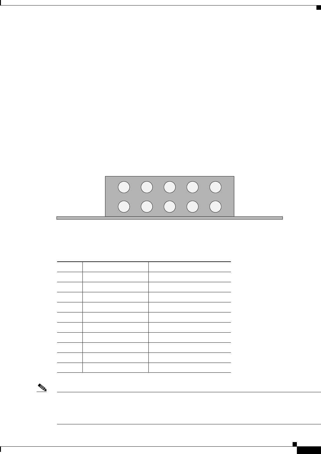
Figure 1-2 shows the 10-pin 10/100 Fast Ethernet header pin locations.
Figure 1-2 MARC Ethernet Header Pin Locations
Table 1-1 describes the pin assignments shown in Figure 1-2.
74521
1
6
2
7
3
8
4
9
5
10
Board edge Board edge
Table 1-1 MARC Ethernet Header Pin Assignments
Pin Signal Description
1 TX+ Transmit Positive
6 TX- Transmit Negative
2 RX+ Receiving Positive
7 Unused Terminated
3 Unused Terminated
8 RX- Receiving Negative
1-4
Cisco 3200 Series Mobile Access Router Hardware Guide
OL-5816-04
Chapter 1 Mobile Access Router Card (MARC)
MARC Component Systems
The FastEthernet 0/0 port on the MARC is a 10/100 Fast Ethernet router port. The FastEthernet ports on
the 4-port FESMIC and the 2-port FESMIC are 10/100 Fast Ethernet switch ports. The routing features
supported on the MARC cannot be configured on the FESMIC ports.
Console, Auxiliary, LED Signals, and Power
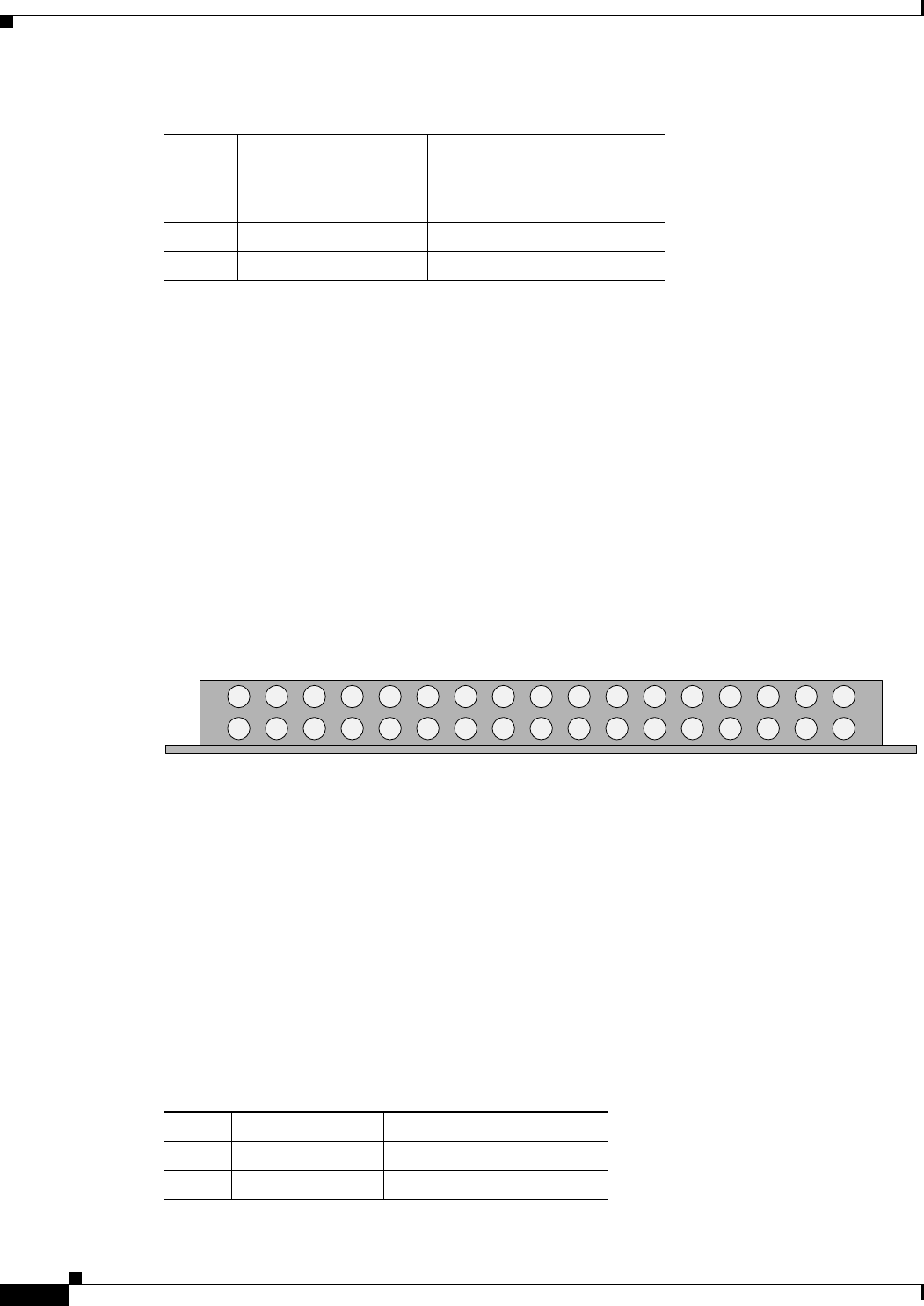
Figure 1-3 shows the 34-pin multifunction header that provides console, AUX and GPS connectivity.
A small footprint +3.3V/+12V dual RS-232 transceiver drives the RS-232 lines. It supports full
modem control signals DTR, CD, RTS, and CTS. The transceiver is connected directly to SMC-1 on
the MPC8250. The serial baud rates can be between 9,600 to 115,000bps.
The same +3.3V/+12V dual RS232 transceiver—Maxim’s MAX3209E—drives the RS-232 lines. It
supports full modem control signals DTR, CD, RTS, and CTS. The transceiver is connected directly to
SCC-1 on the MPC8250. The serial baud rates can be between 9,600 and 115,000bps.
Figure 1-3 MARC Multifunction Header Pin Locations
Console Connections
You can configure the console interface by using IOS command line interface (CLI) commands. The
console interface and the AUX port can be accessed simultaneously. For example, you can connect a
terminal to the console interface and an external modem or a GPS to the AUX port.
The console port signals are provided through the multifunction header:
•Asynchronous serial DCE
•1.2 Kbps, 2.4 Kbps, 4.8 Kbps, 9.6 Kbps, 19.2 Kbps, 38.4 Kbps, 57.6 Kbps, and 115.2 Kbps baud
rates
•Support full modem control DTR, DSR, RTS, and CTS signals
4 Unused Terminated
9 Unused Terminated
5 Reserved Do not use
10 Reserved Do not use
Table 1-1 MARC Ethernet Header Pin Assignments (continued)
Pin Signal Description
74522
Board edge Board edge
17 16 15 14 13 12 11 10 9 8 7 6 5 4 3 2 1
34 33 32 31 30 29 28 27 26 25 24 23 22 21 20 19 18
Table 1-2 MARC Multifunction Header Console Interface Pin Assignments
Pin Signal Description
1 CON_RTS_OUT Request To Send
18 CON_DTR_OUT Data Terminal Ready

1-5
Cisco 3200 Series Mobile Access Router Hardware Guide
OL-5816-04
Chapter 1 Mobile Access Router Card (MARC)
MARC Component Systems
AUX Connections
The AUX port is a serial asynchronous port that works at speeds of 1.2 Kbps, 2.4 Kbps, 4.8 Kbps,
9.6 Kbps, 19.2 Kbps, 38.4 Kbps, 57.6 Kbps, and 115.2 Kbps. The console port and AUX port can be
accessed simultaneously. For example, you can connect a terminal to the console interface and an
external modem or a GPS modem to the AUX port.
The AUX port supports the following:
•Asynchronous serial DTE
•Baud rates range from 1,200 to 115,000
•5 to 8 data bits
•1, 1.5, or 2 stop bits
•Odd, even, or no parity
•Flow control by using RTS, CTS, DTR, and CDC signals
2 CON_TXD_OUT Transmit Data
19 GND Ground
3 GND Ground
20 CON_RXD_IN Receive Data
4 CON_DSR_IN Data Set Ready
21 CON_CTS_IN Clear To Send
Table 1-2 MARC Multifunction Header Console Interface Pin Assignments (continued)
Pin Signal Description
Table 1-3 MARC Multifunction Header AUX Pin Assignments
Pin Signal Description
5 AUX_RTS_OUT Request To Send
22 AUX_DTR_OUT Data Terminal Ready
6 AUX_TXD_OUT Transmit Data
23 GND Ground
7 AUX_DSR_IN Data Set Ready
24 AUX_RXD_IN Receive Data
8 AUX_CD_IN Carrier Detect
25 AUX_CTS_IN Clear To Send
1-6
Cisco 3200 Series Mobile Access Router Hardware Guide
OL-5816-04
Chapter 1 Mobile Access Router Card (MARC)
MARC Component Systems
LED Connections
Table 1-4 shows the MARC LEDs supported through the multifunction header that indicate system and
LAN status.
Power Connections (AUX)
A +5V power supply is provided for device connected to AUX port. A GPS modem is used as an example
in this section. Typically the +5V power supply current to GPS modems should be limited to less than
200 mA.
Table 1-5 shows the pin assignments for power.
MARC Power Requirements
The MARC uses +3.3 V, +5 V, and +12 V power sources. Internal on-board DC-to-DC conversion
circuitry generates 1.8 V/1.5 amps from the +3.3V power source.
Table 1-4 MARC LEDs Multifunction Header Pin Assignments
Pin Signal Description Function Indicates
10 LED_PWR Power–up status LED - (1) Indicates the router operating status. The LED blinks
during IOS bootup and is continuously on after the router
completes its self-test and begins operating. If the
ROMMON self–tests fail, this LED will be off.
27 +3.3V LED power supply LED + (1)
11 LED_LAN_ACT LAN activity status LED - (2) Blinks when a packet is either transmitted or received on
10/100 Fast Ethernet port.
28 +3.3V LED power supply LED + (2)
12 LED_LAN_LINK LAN link indicator LED - (3) Indicates the status of the 10/100 Fast Ethernet port. The
LED is on while the Ethernet link is up and connected to
another device.
29 +3.3V LED power supply LED + (3)
Table 1-5 MARC Multifunction Header Pin Assignments for Power
Pin Signal Description Function
9 GND Ground GND
26 +5V +5V DC Power Supply Power
Table 1-6 MARC Voltages
Voltage Current Power
+5.0 V 0.3 amps 1.5 W
+12.0 V 0.1 amps 1.2 W
+3.3 V 2.0 amps 6.6 W

CHAPTER
2-1
Cisco 3200 Series Mobile Access Router Hardware Guide
OL-5816-04
2
Fast Ethernet Switch Mobile Interface Card
(FESMIC)
The Fast Ethernet Switch Mobile Interface Card (FESMIC) is a mobile interface card (MIC) in a
standard PC/104-Plus form factor. FESMICs are components of the Cisco 3200 Series Mobile Access
Router. The 4-port FESMIC provides 4 sets of switched 10/100 Fast Ethernet signals. The
2-port FESMIC provides 2 sets of switched 10/100 Fast Ethernet signals.
The key features of the FESMIC include the following:
•Auto-sensing switched 10/100 Fast Ethernet interfaces.
•Auto-MDIX (medium-dependent interface crossover). Auto-MDIX automatically detects and
corrects crossed Ethernet cabling.
•Support for 802.1D standard bridging, 802.1Q trunking, and 802.1P class of service (CoS).
•Layer 3 routing support between VLANs.
Additional cards and components provide power and link interfaces to the FESMIC. The exact
configuration of your router will vary, depending on how it was configured by your vendor.
Note This section provides basic information about the FESMIC hardware for the purpose of performing
simple troubleshooting, such as reconnecting a loose cable. To solve more difficult problems, please
contact your vendor.
The FESMIC draws power from the PCI and the ISA connectors. Table 2-1 shows the estimated power
consumption. Note that these are theoretical maximum wattages.
Table 2-1 FESMIC Estimated Power Consumption
Voltage Current Draw Power Source
+5.0 V 0.2 amps 1.0 W ISA and PCI connectors
+3.3 V 2.3 amps 7.7 W PCI connectors

2-2
Cisco 3200 Series Mobile Access Router Hardware Guide
OL-5816-04
Chapter 2 Fast Ethernet Switch Mobile Interface Card (FESMIC)
Auto-Negotiation and Auto-MDI/MDIX
Auto-Negotiation and Auto-MDI/MDIX
All of the 10/100 Fast Ethernet interfaces support Ethernet auto-negotiation for the line transmission
speed. Both sides of the connection are automatically set to either 10BASE-TX or 100BASE-TX.
Auto-negotiation is widely used on most Ethernet interfaces, and it is the default mode.
When a 10/100 Fast Ethernet interface is enabled, one end of the link must perform media dependent
interface (MDI) crossover (MDIX), so that the transmitter on one end of the data link is connected to the
receiver on the other end of the data link (a crossover cable is typically used). The Auto-MDIX feature
eliminates the need for crossover cabling by performing an internal crossover when a straight cable is
detected during the auto-negotiation phase.
If auto-negotiation is disabled, Auto-MDI/MDIX cannot work because there is no signal transmission at
initialization to sample the cabling with. Therefore, as in all systems not supporting the HP Auto-MDIX
feature, cabling must be correct for the devices being connected. The Auto-MDIX feature is disabled if
you explicitly set the line speed rather than leaving the default mode of auto-negotiation. Although it is
possible to disable HP Auto-MDIX with auto-negotiation enabled, the current software does not
implement an explicit CLI command to allow you to disable Auto-MDIX during auto-negotiation.
Auto-negotiation Enable
To enable auto-negotiation, do the following:
Router#(config) FastEthernet m/n
Router#(config-if) speed auto
where m is the slot and n is the port number.
Auto-negotiation Disable
To disable auto-negotiation and auto-MDIX by forcing the line speed through a manual setting, do the
following:
Router#(config) FastEthernet m/n
Router#(config-if) speed 10
or
Router#(config) FastEthernet m/n
Router#(config-if) speed 100
MAC Address Allocation
The 4-port FESMIC stores 4 unique MAC addresses for the 10/100 Ethernet interfaces. The
2-port FESMIC stores 2 unique MAC addresses for the 10/100 Ethernet interfaces. In addition, 33
unique MAC addresses are burned into the Mobile Access Router Card (MARC) to support the FESMIC
per-VLAN spanning tree (PVST) and inter-VLAN routing features.
To provide support for up to 32 VLANs, and the 32 Spanning Tree Protocol (STP) sessions that might
be running, 32 unique MAC addresses required for the bridge packet data unit (BPDU) IDs. In addition,
one MAC address is needed by the FESMIC for VLAN routing., bringing the total of number of MAC
addresses on the wired router to 34. The MAC addresses are burned in the MARC, instead of the
FESMIC to support future development.
2-3
Cisco 3200 Series Mobile Access Router Hardware Guide
OL-5816-04
Chapter 2 Fast Ethernet Switch Mobile Interface Card (FESMIC)
FESMIC Component Systems
FESMIC Component Systems
The ISA buses and PCI buses on the Cisco 3200 Series Mobile Access Router cards provide power to
the components on the cards. Both buses comply with the PC/104-Plus standard. The ISA bus allows
PC/104-Plus ISA signals to pass through the card bus, but the Cisco cards do not use any of the signals.
The PCI bus signals allow the Cisco cards to communicate. Non-Cisco cards cannot communicate with
the Cisco 3200 Series Mobile Access Router cards over the PCI bus.
Caution If you add non-Cisco cards that generates signals on the PCI bus, the router might shut down. Please do
not add non-Cisco cards that generate signals on the PCI bus.
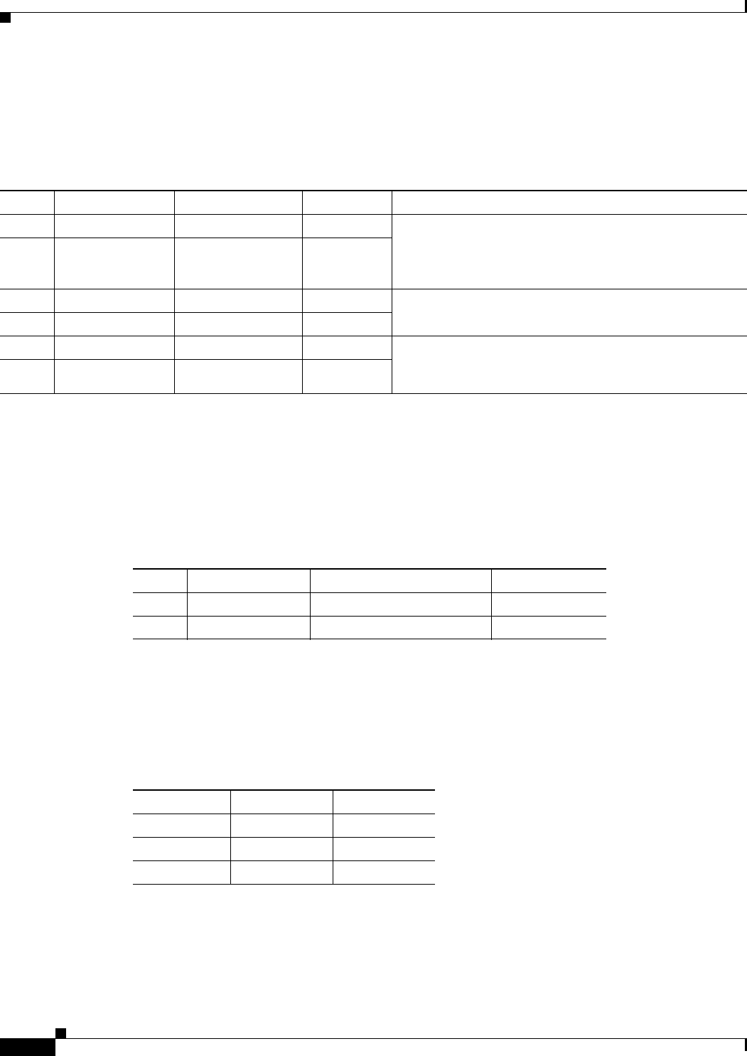
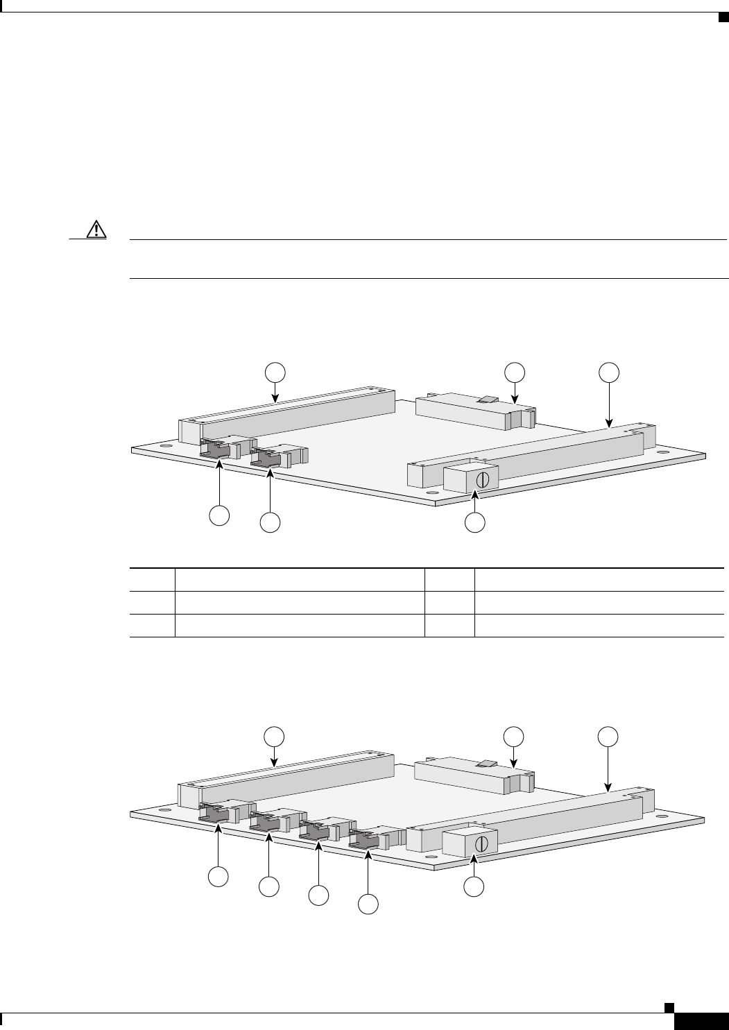
Figure 2-1 shows the 2-port FESMIC header and bus locations.
Figure 2-1 2-port FESMIC Header and Bus Locations
Figure 2-2 shows the 4-port FESMIC header and bus locations.
Figure 2-2 4-port FESMIC Header and Bus Locations
1PCI bus 220-pin LED header
3ISA bus 4Rotary switch
5FE0 10/100 Fast Ethernet header 6FE1 10/100 Fast Ethernet header
95228
1 32
46
5
81598
1 32
46 78
5

2-4
Cisco 3200 Series Mobile Access Router Hardware Guide
OL-5816-04
Chapter 2 Fast Ethernet Switch Mobile Interface Card (FESMIC)
FESMIC Component Systems
Note The PC/104-Plus standard requires that the PCI bus and the ISA bus utilize keying features in the
standard stacking headers to guarantee proper module installation. On the PCI bus, pin D30 is removed
and the D30 opening is plugged. On the ISA bus, pin C19 and pin B10 are removed, and the C19 and
B10 openings are plugged.
Signals for the FESMIC
Cisco 3200 Series router cards do not support any ISA bus signals. The PCI bus connector supports
communication between Cisco 3200 Series Mobile Access Router cards.
Note Non-Cisco MIC cards cannot use PCI signals. The use of PCI signals by non-Cisco cards causes
unpredictable results. You cannot add third-party devices that might attempt to communicate with the
router through the ISA or PCI bus.
The signals are delivered through 10-pin headers, one set of 10/100 Fast Ethernet signals per header.
LED signals and 5 V of power are provided through the 20-pin LED header.
10/100 Fast Ethernet Signals on the FESMIC
There are 4 fixed 10/100 Fast Ethernet signals on the FESMIC. A Cisco router identifies a 10/100 Fast
Ethernet interface address by its slot number and port number, in the form of slot/port. The slot/port
addresses of the 10/100 Fast Ethernet interfaces on the FESMIC depend on the position of the rotary
switch.
For example, if the rotary switch on the 4-port FESMIC is in position 0, the ports are identified as 1/0,
1/1, 1/2, and 1/3. If the rotary switch on the 2-port FESMIC is in position 0, the ports are identified as
1/0 and 1/1.
The 10/100 Fast Ethernet port signals are in compliance with IEEE 802.3. They are provided through the
Ethernet headers, which support the following:
•Auto-negotiation for 10/100BASE-TX connection
•Full-duplex and half-duplex modes
•Low-power sleep mode
•10BASE-T and 100BASE-TX using a single Ethernet connection
•Robust baseline wander correction performance
•Standard carrier signal multiple access collision detect (CSMA/CD) or full-duplex operation
•Integrated LED drivers
1PCI bus 220-pin LED header
3ISA bus 4Rotary switch
5-8 E0–E3 10/100 Fast Ethernet headers
2-5
Cisco 3200 Series Mobile Access Router Hardware Guide
OL-5816-04
Chapter 2 Fast Ethernet Switch Mobile Interface Card (FESMIC)
FESMIC Component Systems
The FastEthernet ports on the 4-port FESMIC and the 2-port FESMIC are 10/100 Fast Ethernet switch
ports. The switch ports support all layer 2 features. The FastEthernet 0/0 port on the MARC is a
10/100 Fast Ethernet router port. The routing features supported on the MARC cannot be configured on
the FESMIC ports.
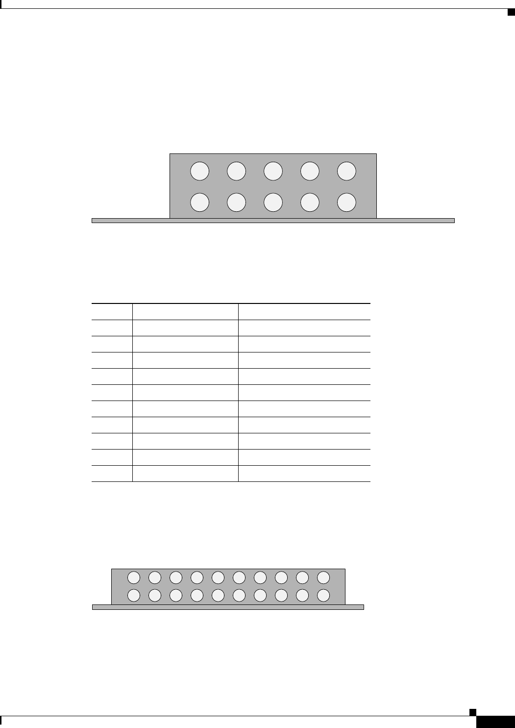
Figure 2-3 shows the 10-pin 10/100 Fast Ethernet header pin locations.
Figure 2-3 FESMIC Ethernet Header Pin Locations
Table 2-2 describes the pin assignments shown in Figure 2-3.
FESMIC LED Signals
Figure 2-4 shows the 20-pin LED header that provides connections for the LEDs.
Figure 2-4 FESMIC LED Header Pin Locations
Table 2-3 lists the pin assignments on the FESMIC 20-pin LED header.
74521
1
6
2
7
3
8
4
9
5
10
Board edge Board edge
Table 2-2 FESMIC Ethernet Header Pin Assignments
Pin Signal Description
1 RX+ Receive positive
6 RX- Receive negative
2 TX+ Transmit positive
7 Unused Terminated
3 Unused Terminated
8 TX- Transmit negative
4 Unused Terminated
9 Unused Terminated
5 Reserved Do not use
10 Reserved Do not use
81599
Board edge Board edge
10 9 8 7 6 5 4 3 2 1
20 19 18 17 16 15 14 13 12 11

2-6
Cisco 3200 Series Mobile Access Router Hardware Guide
OL-5816-04
Chapter 2 Fast Ethernet Switch Mobile Interface Card (FESMIC)
FESMIC Component Systems
Table 2-3 FESMIC LED Header Pin Assignments
Pin Signal Description
1 Port0 LINK+ Link Positive LED terminal Port 0
(power supply)
The LED is on while the
10/100 Fast Ethernet link is up
and connected to another device.
11 Port0 LINK- Link Negative LED terminal Port 0
2 Port0 ACT+ Active Positive LED terminal Port 0
(power supply)
Blinks when a packet is either
transmitted or received.
12 Port0 ACT- Active Negative LED terminal Port 0
3 Port1 LINK+ Link Positive LED terminal Port 1
(power supply)
The LED is on while the
10/100 Fast Ethernet link is up
and connected to another device.
13 Port1 LINK- Link Negative LED terminal Port 1
4 Port1 ACT+ Active Positive LED terminal Port 1
(power supply)
Blinks when a packet is either
transmitted or received.
14 Port1 ACT- Active Negative LED terminal Port 1
5 Port2 LINK+ Link Positive LED terminal Port 2
(power supply)
The LED is on while the
10/100 Fast Ethernet link is up
and connected to another device
(4-port FESMIC only).
15 Port2 LINK- Link Negative LED terminal Port 2
6 Port2 ACT+ Active Positive LED terminal Port 2
(power supply)
Blinks when a packet is either
transmitted or received
(4-port FESMIC only).
16 Port2 ACT- Active Negative LED terminal Port 2
7 Port3 LINK+ Link Positive LED terminal Port 3
(power supply)
The LED is on while the
10/100 Fast Ethernet link is up
and connected to another device
(4-port FESMIC only).
17 Port3 LINK- Link Negative LED terminal Port 3
8 Port3 ACT+ Active Positive LED terminal Port 3
(power supply)
Blinks when a packet is either
transmitted or received
(4-port FESMIC only).
18 Port3 ACT- Active Negative LED terminal Port 3
9 Open Do not use
19 Open Do not use
10 Open Do not use
20 Open Do not use
2-7
Cisco 3200 Series Mobile Access Router Hardware Guide
OL-5816-04
Chapter 2 Fast Ethernet Switch Mobile Interface Card (FESMIC)
FESMIC Component Systems
FESMIC Rotary Switch Positions
The rotary switch position determines the IOS port number for the MIC. Table 2-4 shows the mapping
of the switch positions to the IOS slot numbers.
Caution The rotary switch positions must be unique and should not be assigned to more than one MIC.
If a MIC rotary switch is set to 3 or higher, the message is:
“MIC-3-SLOTNOTSUPPORTED: The MIC cannot operate when the rotary switch is in position 3.
Change the switch position to one of the supported, unused positions 0-2.”
If two or more MICs have the rotary switches set to the same position, or if one or more MICs are in
rotary switch position 4 through 7, the router might crash after displaying the following error message:
“Non-recoverable error occurred. Please check the rotary switch positions on the MIC cards for the
possible misconfiguration of the switch position.”
Table 2-5 shows the FESMIC 10/100 Fast Ethernet signal assignments. The position of the rotary switch
determines the port assignments. Although the rotary switch has eight positions, only one of three
positions can be selected. The rotary switch position should be unique for each MIC.
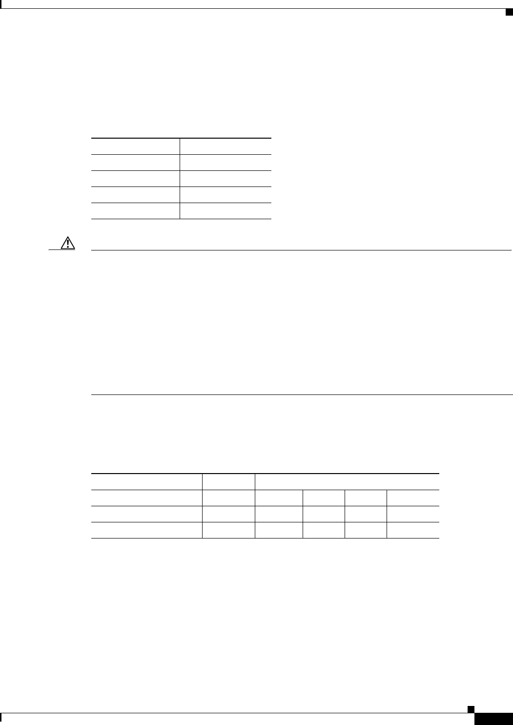
Table 2-4 FESMIC Rotary Switch Positions
Switch Position IOS Slot Number
01
12
23
3–7 Not supported
Table 2-5 FESMIC Rotary Switch Positions and Signal Assignments
Rotary Switch Position MIC Slot Fast Ethernet Signal Assignments
0 1 FE 1/0 FE 1/1 FE 1/21
1. 4-port FESMIC only
FE 1/31
1 2 FE 2/0 FE 2/1 FE 2/21FE 2/31
2 3 FE 3/0 FE 3/1 FE 3/21FE 3/31

2-8
Cisco 3200 Series Mobile Access Router Hardware Guide
OL-5816-04
Chapter 2 Fast Ethernet Switch Mobile Interface Card (FESMIC)
FESMIC Component Systems

CHAPTER
3-1
Cisco 3200 Series Mobile Access Router Hardware Guide
OL-5816-04
3
Serial Mobile Interface Card (SMIC)
The Serial Mobile Interface Card (SMIC) is one component of the Cisco 3200 Series Mobile Access
Router. It provides the router up to 4 high–speed sets of serial signals in both data terminal equipment
(DTE) and data circuit equipment (DCE) modes. Additional components provide power and link
interfaces to the SMIC. For example, the Mobile Access Router Card (MARC) provides the host
processor, memory, and headers for the 10/100 Fast Ethernet, console, and auxiliary signals for the
router. The exact configuration of your router will vary, depending on how it was configured by your
vendor.
Note This section provides basic information about the SMIC hardware for the purpose of performing simple
troubleshooting, such as reconnecting a loose cable. To solve more difficult problems, please contact
your vendor.
Each SMIC provides the following:
•Support for 2 to 4 sets of serial signals with protocol support for HDLC, asynchronous, synchronous
and octet-oriented PPP modes. The signals can be configured to any serial standard (EIA/TIA-232,
EIA/TIA-449, EIA/TIA-530, EIA/TIA-530A, EIA/TIA-X.21, or CCITT V.35).
•DCE and DTE mode support on each set of serial signals.
•Speeds of 2 Mbps for synchronous data transfer and 115 Kbps for asynchronous data transfer on
each serial interface. All serial standards reach 2 Mbps (for synchronous) except for the
EIA/TIA-232 standard which supports up to 192K.
Note The PCI bus and ISA bus utilize keying features in the standard stacking headers to guarantee proper
module installation. On the PCI bus, pin D30 is removed and the D30 opening plugged. On the ISA Bus,
pin C19 and pin B10 are removed, and the pin C19 and pin B10 openings are plugged.
The SMIC draws power from the PCI and the ISA connectors. Table 3-1 shows the estimated power
consumption. Note that these are theoretical maximum wattages.
Table 3-1 SMIC Estimated Power Consumption
Voltage Current Draw Power Source
+5.0 V 1.0 amps 5.0 W ISA and PCI connectors
+3.3 V 0.5 amps 1.7 W PCI connectors
3-2
Cisco 3200 Series Mobile Access Router Hardware Guide
OL-5816-04
Chapter 3 Serial Mobile Interface Card (SMIC)
SMIC Component Systems
SMIC Component Systems
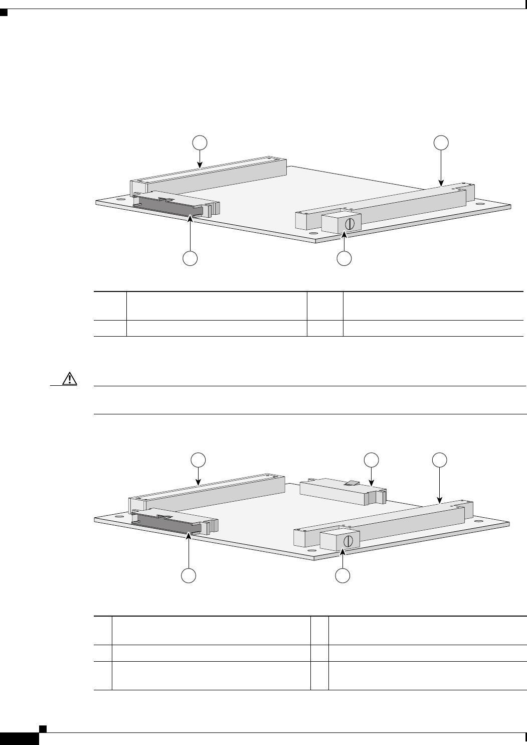
Figure 3-1 shows the 2-port SMIC header and bus locations.
Figure 3-1 2-port SMIC Header and Bus Locations
Figure 3-2 shows the 4-port SMIC header and bus locations.
Caution If you add non-Cisco cards that generates signals on the PCI bus, the router might shut down. Please do
not add non-Cisco cards that generate signals on the PCI bus.
Figure 3-2 4-port SMIC Header and Bus Locations
1PCI bus 260-pin multifunction header for Serial 0
and Serial 1 signals
3ISA bus 4Rotary switch
95227
1 3
24
1PCI bus 260-pin multifunction header for Serial 2 and
Serial 3 signals
3ISA bus 4Rotary switch
560-pin multifunction header for Serial 0 and
Serial 1 signals
74519
1 32
54

3-3
Cisco 3200 Series Mobile Access Router Hardware Guide
OL-5816-04
Chapter 3 Serial Mobile Interface Card (SMIC)
SMIC Component Systems
Signals for the SMIC
The Cisco SSB Serial standard supports the following:
•EIA/TIA-232, EIA/TIA-449, EIA-530, EIA-530A, X.21, and V.35 standards in both DTE or DCE
modes.
•Signals (SSB and LED) are provided through the 60-pin multifunction header(s).
The position of the rotary switch determines the port assignments. Although the rotary switch has eight
positions, only position 0, 1, and 2 are supported on the 4-port SMIC and only position 0 and 1 are
supported on the 2-port SMIC.
Table 3-2 provides 4-port SMIC port assignments.
Table 3-3 provides the 2-port SMIC port assignments.
Serial Cable Length
Maximum Cable length depends on a number of factors, including how well the sender and receiver are
implemented regarding rise times, and cable capacitance, inductance and screening. These are all
difficult to quantify, but the primary factor is the data rate. Typically, doubling the data rate halves the
recommended maximum cable length.
The RS-232 specification limits cable length to 15.25 metres (50 feet) at a maximum data rate of
20,000 bps. The Cisco 3200 Series router RS-232 serial interfaces data rate is 115,200 bps and are
limited to a maximum cable length of 2.8 meters (8 feet).
Table 3-2 4-port SMIC Rotary Switch Settings and Port Assignments
Position MIC Slot Port Assignments
0 1 Serial 1/0 Serial 1/1 Serial 1/2 Serial 1/3
1 2 Serial 2/0 Serial 2/1 Serial 2/2 Serial 2/3
2 3 Serial 3/0 Serial 3/1 Serial 3/2 Serial 3/3
Table 3-3 2-port SMIC Rotary Switch Settings and Port Assignments
Position MIC Slot Port Assignments
0 1 Serial 1/0 Serial 1/1
1 2 Serial 2/0 Serial 2/1

3-4
Cisco 3200 Series Mobile Access Router Hardware Guide
OL-5816-04
Chapter 3 Serial Mobile Interface Card (SMIC)
SMIC Component Systems
SMIC LED Signals
Table 3-4 shows the LED signals that are supported on the SMIC, along with the corresponding
functions. Serial 2 and Serial 3 apply to the 4-port SMIC only.
4-Port SMIC Rotary Switch Positions
Table 3-5 shows the 4-port SMIC serial signal assignments. The position of the rotary switch determines
the port assignments. Although the rotary switch has 8 positions, only 1 of 3 positions can be selected.
The rotary switch position should be unique for each mobile interface card (MIC) card.
Table 3-4 SMIC LED Functions
LED Function
SERIAL0 ACTIVITY Blinks once when a packet is either transmitted or received on Serial 0, and
originates from Header 5.
SERIAL0 LINK Indicates the status of Serial 0 and originates from Header 5. The LED is on
when a serial port is in DTE mode, and when the data set ready (DSR), data
carrier detect (DCD), and clear to send (CTS) signals are detected. The LED
is on when a serial port is in DCE mode, and when the data terminal ready
(DTR) and request to send (RTS) signals have been detected.
SERIAL1 ACTIVITY Blinks once when a packet is either transmitted or received on Serial 1.
Originates from Header 5.
SERIAL1 LINK Indicates the status of Serial 1, and originates from Header 5. The LED is on
when the serial port is in DTE mode, and when the data set ready (DSR), data
carrier detect (DCD), and clear to send (CTS) signals are detected. The LED
is on when the serial port is in DCE mode, and when the data terminal ready
(DTR) and request to send (RTS) signals have been detected.
SERIAL2 ACTIVITY Blinks once when a packet is either transmitted or received on Serial 2.
Originates from Header 2.
SERIAL2 LINK Indicates the status of Serial 2, and originates from Header 2. The LED is on
when the serial port is in DTE mode, and when the data set ready (DSR), data
carrier detect (DCD), and clear to send (CTS) signals are detected. The LED
is on when the serial port is in DCE mode, and when the data terminal ready
(DTR) and request to send (RTS) signals have been detected.
SERIAL3 ACTIVITY Blinks once when a packet is either transmitted or received on Serial 3.
Originates from Header 2.
SERIAL3 LINK Indicates the status of Serial 3, and originates from Header 2. The LED is on
when the serial port is in DTE mode, and when the data set ready (DSR), data
carrier detect (DCD), and clear to send (CTS) signals are detected. The LED
is on when the serial port is in DCE mode, and when the data terminal ready
(DTR) and request to send (RTS) signals have been detected.
Table 3-5 4-port SMIC Rotary Switch Positions and Serial Set Signal Assignments
Rotary Switch Position MIC Slot Signal Assignments
0 1 Serial 1/0 Serial 1/1 Serial 1/2 Serial 1/3
1 2 Serial 2/0 Serial 2/1 Serial 2/2 Serial 2/3

3-5
Cisco 3200 Series Mobile Access Router Hardware Guide
OL-5816-04
Chapter 3 Serial Mobile Interface Card (SMIC)
SMIC Component Systems
2 3 Serial 3/0 Serial 3/1 Serial 3/2 Serial 3/3
3 4 Serial 4/0 Serial 4/1 Serial 4/2 Serial 4/3
Table 3-5 4-port SMIC Rotary Switch Positions and Serial Set Signal Assignments
Rotary Switch Position MIC Slot Signal Assignments

3-6
Cisco 3200 Series Mobile Access Router Hardware Guide
OL-5816-04
Chapter 3 Serial Mobile Interface Card (SMIC)
SMIC Component Systems

CHAPTER
4-1
Cisco 3200 Series Mobile Access Router Hardware Guide
OL-5816-04
4
Wireless Mobile Interface Card (WMIC)
The Wireless Mobile Interface Card (WMIC) is a mobile interface card (MIC) in a standard PC/104-Plus
form factor. It is one component of the Cisco 3200 Series Mobile Access Routers and provides a
2.4-GHz (802.11b/g) or 4.9-GHz (US Only, Public Safety) wireless interface.
The WMIC can be configured as a:
•Wireless Access Point
•Wireless Root Bridge
•Wireless Non-root Bridge
•Wireless Work Group Bridge.
The WMIC communicates with the router through its 10/100 Fast Ethernet interface.
Note This chapter provides basic information about the WMIC hardware for the purpose of performing simple
troubleshooting, such as reconnecting a loose cable. To solve more difficult problems, please contact
your vendor.
Caution The 4.9-GHz (US Only, Public Safety) radio requires an operators license and can only be operated by
US Public Safety operators who meet the requirements specified under FCC Part 90.20.
WMIC Component Systems
The ISA buses and PCI buses on the Cisco 3200 Series Mobile Access Router cards provide power to
the components on the cards. The WMIC does not receive or transmit communications signals on the
buses, but it will pass signals through to a card above or below the WMIC. Both buses comply with the
PC/104-Plus standard.
The PCI bus signals allow the Cisco cards to communicate. Non-Cisco cards cannot communicate with
the Cisco 3200 Series Mobile Access Router cards over the PCI bus.
Caution If you add non-Cisco cards that generates signals on the PCI bus, the router might shut down. Please do
not add non-Cisco cards that generate signals on the PCI bus.
4-2
Cisco 3200 Series Mobile Access Router Hardware Guide
OL-5816-04
Chapter 4 Wireless Mobile Interface Card (WMIC)
WMIC Component Systems
Figure 4-1 shows the WMIC header and bus locations.
Figure 4-1 WMIC Header and Bus Locations
Note The PC/104-Plus standard requires that the PCI bus and the ISA bus utilize keying features in the
standard stacking headers to guarantee proper module installation. On the PCI bus, pin D30 is removed
and the D30 opening is plugged. On the ISA bus, pin C19 and pin B10 are removed, and the C19 and
B10 openings are plugged.
Signals for the WMIC
Cisco 3200 Series router cards do not support any ISA bus signals. The PCI bus connector supports
communication between Cisco 3200 Series Mobile Access Router cards.
Note Non-Cisco MIC cards cannot use PCI signals. The use of PCI signals by non-Cisco cards causes
unpredictable results. You cannot add third-party devices that might attempt to communicate with the
router through the ISA or PCI bus.
The 10/100 Fast Ethernet signals are delivered through a 10-pin header. LED signals and RS-232 console
signals are provided through the 24-pin multifunction header.
1PCI bus 2Left antenna connector (J2)
3Right antenna connector (J1) 4ISA bus
510-pin 10/100 Fast Ethernet header 624-pin multifunction header
103981
4
2
1
3
5
6
4-3
Cisco 3200 Series Mobile Access Router Hardware Guide
OL-5816-04
Chapter 4 Wireless Mobile Interface Card (WMIC)
WMIC Component Systems
10/100 Fast Ethernet Signals on the WMIC
There is one set of fixed 10/100 Fast Ethernet signals on the WMIC. The 10/100 Fast Ethernet port
signals are in compliance with IEEE 802.3. They are provided through the Ethernet headers, which
support the following:
•Auto-negotiation for 10/100BASE-TX connection
•Full-duplex and half-duplex modes
•Low-power sleep mode
•10BASE-T and 100BASE-TX using a single Ethernet connection
•Robust baseline wander correction performance
•Standard carrier signal multiple access collision detect (CSMA/CD) or full-duplex operation
•Integrated LED drivers
Figure 4-2 shows the 10-pin 10/100 Fast Ethernet header pin locations.
Figure 4-2 WMIC Ethernet Header Pin Locations
Table 4-1 describes the pin assignments shown in Figure 4-2.
Note If Auto-MDIX is disabled, when connecting to Ethernet switches or repeaters a straight-through cable
can be used. When connecting to compatible workstations, servers, and routers, a crossover cable should
be used. If Auto-MDIX is enabled, either a straight-through or crossover cable can be used can be used
to make the connection, as the router automatically changes the signals on the pins to compensate.
74521
1
6
2
7
3
8
4
9
5
10
Board edge Board edge
Table 4-1 WMIC Ethernet Header Pin Assignments
Pin Signal Description
1 TX+ Transmit positive
6 TX- Transmit negative
2 RX+ Receive positive
7 Unused Terminated
3 Unused Terminated
8 RX- Receive negative
4 Unused Terminated
9 Unused Terminated
5 Reserved Do not use
10 Reserved Do not use

4-4
Cisco 3200 Series Mobile Access Router Hardware Guide
OL-5816-04
Chapter 4 Wireless Mobile Interface Card (WMIC)
WMIC Component Systems
WMIC Multifunction Header Signals
The multifunction header contains RS-232 console signals and three-color status LED signals.
Figure 4-3 shows the 24-pin multifunction header that provides connections for the LEDs.
Figure 4-3 WMIC Multifunction Header Pin Locations
Table 4-2 lists the pin assignments on the WMIC 20-pin LED header.
103464
Board edge Board edge
9 8 7 6 5 4 3 2 110
20
11
21
12
222324 19 18 17 16 15 14 13
Table 4-2 WMIC Multifunction Header Pin Assignments
Pin Signal
1 Negative Ethernet RED LED terminal
13 Shared Positive Ethernet LED terminal
2 Negative Ethernet GREEN LED terminal
14 Negative Radio/RF RED LED terminal
3 Shared Positive Radio/RF LED terminal
15 Negative Radio/RF GREEN LED terminal
4 Negative Wireless Status RED LED terminal
16 Shared Positive Wireless Status LED terminal
5 Negative Wireless Status GREEN LED terminal
17 Negative Installation RED LED terminal
6 Shared Positive Installation/Operation LED terminal
18 Negative Operation GREEN LED terminal
7 Not Used (No Connection)
19 Console TX - Transmit Data
8 Console RX - Receive Data
20 Console GND - Signal Ground
9 Reserved
21 Reserved
10 Reserved
22 Reserved
11 Reserved
23 Reserved
12 Reserved
24 Reserved

4-5
Cisco 3200 Series Mobile Access Router Hardware Guide
OL-5816-04
Chapter 4 Wireless Mobile Interface Card (WMIC)
WMIC Component Systems
LED Behavior
During normal operations, the indicator signals on the wireless device have the following meanings.
•The status indicator signals operational status. Steady green indicates that the wireless device is
associated with at least one wireless client. Blinking green indicates that the wireless device is
operating normally but is not associated with any wireless devices.
•The radio indicator blinks green to indicate radio traffic activity. The light is normally off, but it
blinks whenever a packet is received or transmitted over the radio.
•The Ethernet indicator signals traffic on the wired LAN. This indicator is normally green when an
Ethernet cable is connected, and blinks green when a packet is received or transmitted over the
Ethernet infrastructure. The indicator is off when the Ethernet cable is not connected.
Table 4-3 shows the details of LED behavior.
Table 4-3 Indicator Signals
Message
type
Ethernet
indicator
Status
indicator
Radio
indicator
Meaning
Boot loader
status
Green – Green DRAM memory test.
– Amber Red Board initialization test.
– Blinking
green
Blinking
green
Flash memory test.
Amber Green – Ethernet initialization test.
Green Green Green Starting Cisco IOS software.
Association
status
– Green – At least one wireless client device is
associated with the unit.
– Blinking
green
– No client devices are associated; check the
wireless device SSID and WEP settings.
Operating
status
–GreenBlinking
green
Transmitting/receiving radio packets.
Green – – Ethernet link is operational.
Blinking
green
– – Transmitting/receiving Ethernet packets.
Boot Loader
Errors
Red – Red DRAM memory test failure.
– Red Red File system failure.
Red Red – Ethernet failure during image recovery.
Amber Green Amber Boot environment error.
Red Green Red No Cisco IOS image file.
Amber Amber Amber Boot failure.
Operation
Errors
–GreenBlinking
amber
Maximum retries or buffer full occurred on
the radio.
Blinking
amber
– – Transmit/receive Ethernet errors.
– Blinking
amber
– General warning.

4-6
Cisco 3200 Series Mobile Access Router Hardware Guide
OL-5816-04
Chapter 4 Wireless Mobile Interface Card (WMIC)
Key Features
Antenna Connector
On the radio card, there are two ultra-miniature coaxial connectors (U.FL connector) that are used to
connect the coax cables between the WMIC and the external antenna connectors. This low profile
connector offers frequency performance up to 6-GHz. Two connectors are used to support antenna
diversity.
The cable should be as short as possible to minimize the loss in strength of the radio frequency (RF)
signal. The cable carries the RF signal from the antenna to the low noise amplifier (LNA) on the receiver
and transmits the RF signal from power amplifier (PA) to the antenna that radiates the RF signal.
There are many antenna connector families. The Cisco RP-TNC antenna connector can be used to
support standard antennas.
Key Features
This section lists the key features of the radios.
2.4-GHz (802.11b/g) WMIC and the 4.9-GHz (US Only, Public Safety) Features
The key features of the 2.4-GHz (802.11b/g) WMIC and the 4.9-GHz (US Only, Public Safety) WMIC
are listed below.
Configuration
Reset
– Amber – Resetting the configuration options to
factory defaults.
Failures Red Red Red Firmware failure; try disconnecting and
reconnecting unit power.
Blinking red – – Hardware failure. The wireless device
must be replaced.
Firmware
Upgrade
– Red – Loading new firmware image.
Table 4-3 Indicator Signals (continued)
Message
type
Ethernet
indicator
Status
indicator
Radio
indicator
Meaning
Table 4-4 WMIC Key Features
Wireless Medium Direct Sequence Spread Spectrum (DSSS)
Orthogonal Frequency Division Multiplexing (OFDM)
Media Access Protocol Carrier sense multiple access with collision avoidance (CSMA/CA)
SNMP Compliance MIB I and MIB II
Encryption Key Length 128-bit
Virtual LAN (VLAN)
Support The segmentation of up to 16 user groups is allowed.
Quality of Service
(QoS) Support Prioritization of traffic for different requirements, such as voice and video.

4-7
Cisco 3200 Series Mobile Access Router Hardware Guide
OL-5816-04
Chapter 4 Wireless Mobile Interface Card (WMIC)
Key Features
Note If no FESMIC is installed, the Cisco 3200 Series routers support a maximum of one WMIC on each
router. The routers support a maximum of three WMICs on each router when a FESMIC is installed.
MAC Address Allocation
The WMIC stores one unique MAC address for the BVI interface.
Security Cisco Wireless Security Suite including:
Authentication:
•802.1X support including LEAP, PEAP, EAP-TLS, EAP-TTLS, and
EAP-SIM to yield mutual authentication and dynamic, per-user,
per-session WEP keys
•MAC address and by standard 802.11 authentication mechanisms
Encryption:
•Support for static and dynamic IEEE 802.11 WEP keys of 40 bits and
128 bits
•Pre-standard TKIP WEP enhancements: key hashing (per-packet
keying), message integrity check (MIC), and broadcast key rotation
Status Indicators LEDs provide information concerning association status, operation,
error/warning, firmware upgrade, and configuration, network/modem, and
radio status
Memory 8MB Flash
32 MB DRAM
Automatic Configuration
Support BOOTP and DHCP
Remote Configuration
Support Telnet, HTTP, FTP, TFTP, and SNMP
Uplink Auto-sensing 10/100BaseT Ethernet
Local Configuration Console port
Table 4-4 WMIC Key Features

4-8
Cisco 3200 Series Mobile Access Router Hardware Guide
OL-5816-04
Chapter 4 Wireless Mobile Interface Card (WMIC)
Key Features
Differences Between 2.4-GHz (802.11b/g) and 4.9-GHz (US Only, Public Safety)
Radios
Table 4-5 Differences between 2.4-GHz WMIC and 4.9-GHz WMIC
2.4-GHz (802.11b/g) 4.9-GHz (US Only, Public Safety) Comment
Power Maximum OFDM power level is
15dbm (30mw), but the power level
might vary by country.
Maximum OFDM power level is
17dbm (50mw).
power client Command Supported Not supported. Use the power
command.
Concatenation Supported. Not supported.
Fragmentation Maximum threshold is 4000 bytes. Maximum threshold is 2346 bytes. Fragment counter is
in units of
fragmented packets.
distance Command (to
minimize delay
propagation)
Supported up to 99 kilometers. Supported up to 3 kilometers (1.8
miles).
World Mode Supported. Not supported.
HTML-Based User
Interface Supported Not supported
VLANs 16 unencrypted VLANs, 16 static key
VLANs, or 16 dynamic key VLANs,
16 unencrypted VLANs, 1 static key
VLAN, or 4 dynamic key VLANs.
Wireless
encryption/cipher
suites
WEP-40, WEP-128, TKIP, CKIP,
CMIC and CKIP-CMIC
WEP-40, WEP-128, TKIP and
AES-CCM
Max Number of
Stations with WEP 255 116
Max Number of
Stations with TKIP 256 26
Max Number of
Stations with
AES-CCM
256 116
WDS server Not supported. The 4.9-GHz WMIC can be configured
to act as WDS server.
WDS client The 2.4-GHz WMIC acting as root
device can auto discover and work with
a subnet WDS server.
The 4.9-GHz WMIC acting as root
device can auto discover and work
within a subnet WDS server. If IP
address of a WDS server is statically
configured on a 4.9-GHz WMIC acting
as root device, the WMIC can also
work with a central WDS server
located anywhere on the network.
EAP-TLS, EAP-TTLS Supported Not Supported
WDS Server related
MIBS N/A Supported

4-9
Cisco 3200 Series Mobile Access Router Hardware Guide
OL-5816-04
Chapter 4 Wireless Mobile Interface Card (WMIC)
Key Features
2.4-GHz (802.11b/g) Features
The key features of the 2.4-GHz (802.11b/g) WMIC are listed below.
Data Rates Supported 1, 2, 5.5, 6, 9, 11, 12, 18, 24, 36, 48, and 54 Mbps
Network Standard IEEE 802.11b and IEEE 802.11g
Frequency Band 2.400-GHz to 2.497-GHz
Modulation BPSK 1Mbps and 6Mbps
QPSK 2 Mbps and 12 Mbps
CCK 5.5 Mbps
BPSK 9.6 Mbps
CCK2 11 Mbps
QPSK 18 Mbps
16 QAM 24 Mbps and 36 Mbps
64 QAM 48 Mbps and 54 Mbps
Operating Channels North America: 11; ETSI: 13; Japan: 14
Receive Sensitivity 1Mbps: -94dBm
2Mbps: -91dBm
5.5 Mbps: -89 dBm
11 Mbps: -85 dBm
Available Transmit Power
Settings 100 mW (20 dBm)
50 mW (17 dBm)
30 mW (15 dBm)
20 mW (13 dBm)
5mW (7dBm)
1mW (0dBm)
Maximum power setting will vary according to individual country
regulations.
Range (typical @ 1000-mW
transmit power setting
with 6 dBi diversity dipole
antenna)
Outdoor:
0.5 mile (804 m) @ 45 Mbps
1 mile (1609 m) @ 11 Mbps
3 miles (4,827 m) @ 1 Mbps
Compliance 2.4-GHz (802.11b/g) operates license free under FCC Part 15 and complies
as a Class B device; complies with DOC regulations; complies with ETS
300.328, FTZ 2100, and MPT 1349 standards; rugged version complies with
UL 2043

4-10
Cisco 3200 Series Mobile Access Router Hardware Guide
OL-5816-04
Chapter 4 Wireless Mobile Interface Card (WMIC)
Key Features
4.9-GHz (US Only, Public Safety) Features
The key features of the 4.9-GHz (US Only, Public Safety) WMIC are listed below.
4.9 -GHz Channels
Table 4-6 shows the channel options for the 4.94-GHz to 4.99-GHz band for the United States regulatory
domain.
Data Rates Supported 5-MHz channelization: 1.5, 2.25, 3, 4.5, 6, 9, 12, and 13.5 Mbps
10-MHz channelization: 3, 4.5, 6, 9, 12, 18, 24, and 27 Mbps
20-MHz channelization: 6, 9, 12, 18, 24, 36, 48, and 54 Mbps
Network Standard Currently there is no IEEE 4.9-GHz (US Only, Public Safety) standard;
however, it is similar to the IEEE 802.11a standard.
Frequency Band 4.940-GHz to 4.990-GHz
Operating Channels North America: 11
Available Transmit Power
Settings 40 mW (16 dBm)
30 mW (15 dBm)
20 mW (13 dBm)
10 mW (10 dBm)
5mW (7dBm)
Compliance 4.9-GHz (US Only, Public Safety):
•Operation restricted to operators meeting requirements of CFR47 Part
90.20 of the technical rules for qualification as a Public Safety operator.
•Requires a FCC license to operate under this part of the Part 90
Regulation
Table 4-6 FCC 4.9 Operational Channels as per TIA TR-8 specification
Operating Channel
Numbers
Channel Center 5-MHz
Channel Spacing
Channel Center 10-MHz
Channel Spacing
Channel Center 20-MHz
Channel Spacing
1
3
5 4942.5
7
9
10 4945.0
15 4947.5
20 4950.0 4950.0
25 4952.5

4-11
Cisco 3200 Series Mobile Access Router Hardware Guide
OL-5816-04
Chapter 4 Wireless Mobile Interface Card (WMIC)
Key Features
Note Channel Center Frequencies (MHz) 1-MHz Channel Spacing is documented in the TIA TR-8
specification, but it is not supported by the 4.9-GHz (US Only, Public Safety) WMIC.
Throughput
The throughput is a minimum of:
•4 Mbps half-duplex at one mile line-of-sight for a 5-MHz-wide channel
•8 Mbps half-duplex at one mile line-of-sight range for a 10-MHz-wide channel.
•16 Mbps half-duplex at one mile line-of-sight range for a 20-MHz-wide channel.
30 4955.0 4955.0
35 4957.5
40 4960.0 4960.0
45 4962.5
50 4965.0 4965.0
55 4967.5
60 4970.0 4970.0
65 4972.5
70 4975.0 4975.0
75 4977.5
80 4980.0 4980.0
85 4982.5
90 4985.0
91
93
95 4987.5
97
99
Table 4-6 FCC 4.9 Operational Channels as per TIA TR-8 specification (continued)
Operating Channel
Numbers
Channel Center 5-MHz
Channel Spacing
Channel Center 10-MHz
Channel Spacing
Channel Center 20-MHz
Channel Spacing

4-12
Cisco 3200 Series Mobile Access Router Hardware Guide
OL-5816-04
Chapter 4 Wireless Mobile Interface Card (WMIC)
Power Requirements
Modulation
Table 4-7 shows the modulation.
Receive Sensitivity
Table 4-8 shows the receive sensitivity.
Power Requirements
Additional cards and components provide power and link interfaces to the WMIC. The exact
configuration of your router will vary, depending on how it was configured by the vendor.
The WMIC draws power from the PCI and the ISA connectors. Table 4-9 shows the estimated power
consumption. Note that these are theoretical maximum wattages.
Table 4-7 Modulation
Modulation 5 Mbps 10 Mbps 20 Mbps
BPSK 1.5 Mbps and 2.25 Mbps 3 Mbps and 4.5 Mbps 6 Mbps and 9 Mbps
QPSK 3 Mbps and 4.5 Mbps 6 Mbps and 9 Mbps 12 Mbps and 18 Mbps
16 QAM 6 Mbps and 9 Mbps 12 Mbps and 18 Mbps 24 Mbps and 27 Mbps
64 QAM 12 Mbps and 13.5 Mbps 24 Mbps and 27 Mbps 48 Mbps and 54 Mbps
Table 4-8 Receive Sensitivity
5-MHz 10-MHz 20-MHz
1.5 Mbps -89 dBm 3 Mbps -87 dBm 6 Mbps -85 dBm
2.25 Mbps -89 dBm 4.5 Mbps -87 dBm 9 Mbps -85 dBm
3Mbps -89 dBm 6 Mbps -87 dBm 12 Mbps -85 dBm
4.5 Mbps -85 dBm 9 Mbps -87 dBm 18 Mbps -82 dBm
6 Mbps -82 dBm 12 Mbps -85 dBm 24 Mbps -79 dBm
9 Mbps -79 dBm 18 Mbps -79 dBm 36 Mbps -76 dBm
12 Mbps -74 dBm 24 Mbps -74 dBm 48 Mbps -71 dBm
13.5 Mbps -72 dBm 27 Mbps -72 dBm 54 Mbps -69 dBm
Table 4-9 WMIC Power Requirement
Voltage Current Draw Power Source
+5.0 V 0.4 amps 2.0 W ISA and PCI connectors
+3.3 V 1.7 amps 5.6 W PCI connectors

4-13
Cisco 3200 Series Mobile Access Router Hardware Guide
OL-5816-04
Chapter 4 Wireless Mobile Interface Card (WMIC)
Related Documentation
Related Documentation
These documents provide detailed information regarding the configuration of the wireless card:
•Cisco IOS Switching Services Configuration Guide. Click this link to browse to this document:
http://www.cisco.com/univercd/cc/td/doc/product/software/ios122/122cgcr/fswtch_c/index.htm
•Cisco Internetwork Design Guide. Click this link to browse to this document:
http://www.cisco.com/univercd/cc/td/doc/cisintwk/idg4/index.htm
•Cisco Internetworking Technology Handbook. Click this link to browse to this document:
http://www.cisco.com/univercd/cc/td/doc/cisintwk/ito_doc/index.htm
•Cisco Internetworking Troubleshooting Guide. Click this link to browse to this document:
http://www.cisco.com/univercd/cc/td/doc/cisintwk/itg_v1/index.htm

4-14
Cisco 3200 Series Mobile Access Router Hardware Guide
OL-5816-04
Chapter 4 Wireless Mobile Interface Card (WMIC)
Related Documentation

IN-1
Cisco 3200 Series Mobile Access Router Hardware Guide
OL-5816-04
INDEX
Numerics
10/100 Fast Ethernet
auto-negotiation 2-2
signals 1-1, 2-1, 4-1
2.4-GHz (802.11b/g) WMIC 4-1
3rd-party devices 1-2
4.9-MHz (public safety) WMIC 4-1
802.1D 2-1
802.1P 2-1
802.1Q 2-1
A
asynchronous
AUX 1-1, 1-5
baud rates 1-4
data transfer 3-1
DTE 1-5
GPS 1-1
audience ii
Auto-MDIX 2-1, 2-2, 4-3
auto negotiation 1-1
auto-negotiation 2-2
AUX interface
signals 1-4
specifications 1-5
B
baud rate, serial 1-4
bridge packet data unit (BPDU) 2-2
bridging 2-1
broadcast key rotation 4-9
bus communication 1-2, 2-3, 3-1, 4-1
bus keying feature 1-2, 2-4, 3-1, 4-2
C
cards
Cisco FESMIC 2-1
Cisco MARC 1-1
Cisco SMIC 3-1
Cisco WMIC 4-1
CCITT V.35 3-1
Cisco FESMIC 2-1
Cisco MARC 1-4
Cisco SMIC 3-1
Cisco WMIC 4-4, 4-6, 4-7, 4-9
class of service (CoS) 2-1
console port
MARC signals 1-4
WMIC signals 4-4
console port interface
Cisco MARC 1-4
Cisco WMIC 4-4
crossover cable 2-2
D
DCE mode 3-1
disabling auto-negotiation 2-2
DRAM 1-1
DTE
asynchronous 1-5
mode 3-1

Index
IN-2
Cisco 3200 Series Mobile Access Router Hardware Guide
OL-5816-04
E
EIA/TIA-232 3-1
EIA/TIA-449 3-1
EIA/TIA-530 3-1
EIA/TIA-530A 3-1
EIA/TIA-X.21 3-1
enabling auto-negotiation 2-2
Ethernet
header 1-3
indicator 4-5
F
Fast Ethernet
header pin locations
Cisco FESMIC 2-5
Cisco MARC 1-3
Cisco WMIC 4-3
interface
Cisco FESMIC 2-4
Cisco MARC 1-3
Cisco WMIC 4-3
router port 1-4
signals
Cisco FESMIC 2-1
Cisco MARC 1-1
Cisco WMIC 4-1
switch port 1-4, 2-5
Flash memory 1-1
flow control 1-5
G
GPS
modem 1-5
power 1-6
H
HDLC 3-1
header keying 1-2, 2-4, 3-1, 4-2
header locations
Cisco FESMIC 2-3
Cisco MARC 1-2
Cisco SMIC 3-2
Cisco WMIC 4-2
I
industry-standard architecture (ISA) 1-2
interface identification
Fast Ethernet
Cisco FESMIC 2-4
Cisco MARC 1-3
Cisco WMIC 4-3
serial
Cisco MARC 1-4
Cisco SMIC 3-4
interfaces
AUX 1-5
Cisco FESMIC 2-4
Cisco MARC 1-3
Cisco SMIC 3-1
Cisco WMIC 4-2, 4-3
console port 1-4, 4-4
Fast Ethernet
Cisco FESMIC 2-4
Cisco MARC 1-3
Cisco WMIC 4-2, 4-3
serial
Cisco MARC 1-1
Cisco SMIC 3-4
inter-VLAN routing 2-2
ISA bus
signals 1-2, 2-3, 4-1

Index
IN-3
Cisco 3200 Series Mobile Access Router Hardware Guide
OL-5816-04
K
key hashing 4-9
keying feature 1-2, 2-4, 3-1, 4-2
L
LEAP 4-9
LED
Cisco FESMIC 2-4
Cisco MARC 1-3
Cisco SMIC 3-4
Cisco WMIC 4-2
LED indicators
Ethernet 4-5
radio traffic 4-5
status 4-5
M
MAC address 2-2, 4-10
MDIX 2-2
media dependent interface (MDI) 2-2
medium-dependent interface crossover 2-1
memory
Flash 1-1
PC system requirements vii
message integrity check 4-9
Mobile Access Router Card 1-1
modem
AUX connection 1-5
control signals 1-4
DTR, DSR, RTS, and CTS signals 1-4
GPS modem 1-5
multifunction header 1-3, 1-4
N
non-Cisco cards
bus communication 1-2, 2-3, 3-1, 4-1
P
PC-104-Plus 1-2
PCI bus 1-2, 2-3, 4-1
PCI bus version 1-1
PEAP 4-9
per-VLAN spanning tree (PVST) 2-2
ports
AUX signals 1-4
console signals 1-4, 4-4
Fast Ethernet interface signals 1-1, 2-1, 4-1
serial interface signals 1-1
power consumption
Cisco FESMIC 2-1
Cisco MARC 1-6
Cisco SMIC 3-1
Cisco WMIC 4-10
PPP modes 3-1
processor 1-1
Q
QoS 4-9
R
radio
indicator 4-5
range 4-7
rotary switch 3-3
Cisco FESMIC 2-7
Cisco SMIC 3-4
router cards

Index
IN-4
Cisco 3200 Series Mobile Access Router Hardware Guide
OL-5816-04
Cisco FESMIC 2-1
Cisco MARC 1-1
Cisco SMIC 3-1
Cisco WMIC 4-1
RS232 transceiver 1-4
S
serial
asynchronous port 1-5
baud rates 1-4
signals 1-1, 3-1
serial interface
Cisco MARC 1-1
Cisco SMIC 3-4
signals
Cisco FESMIC 2-4
Cisco MARC 1-3
Cisco SMIC 3-3
Cisco WMIC 4-2
Fast Ethernet 1-3, 2-1, 4-1
ISA bus 1-2, 2-3, 4-1
PCI bus 1-2, 2-3, 4-1
serial 1-3, 3-3
Spanning Tree Protocol (STP) 2-2
status indicators 4-5
switch, rotary 2-7
synchronous 3-1
system requirements vii
T
third-party devices 2-4, 4-2
TKIP 4-9
trunking 2-1
V
VLAN routing 2-2
W
WEP 4-9
WMICs 4-1
Z
zeroization 1-1