Clarion HGZ0036 Car equipment unit User Manual Manual
Clarion Co., Ltd Car equipment unit Manual
UserManual.wiki
>
Clarion
>
HGZ0036 User Manual
Manual
Navigation menu
Upload a User Manual
Namespaces
Wiki Guide
HTML
PDF
Info
Views
User Manual
Discussion / Help
Navigation
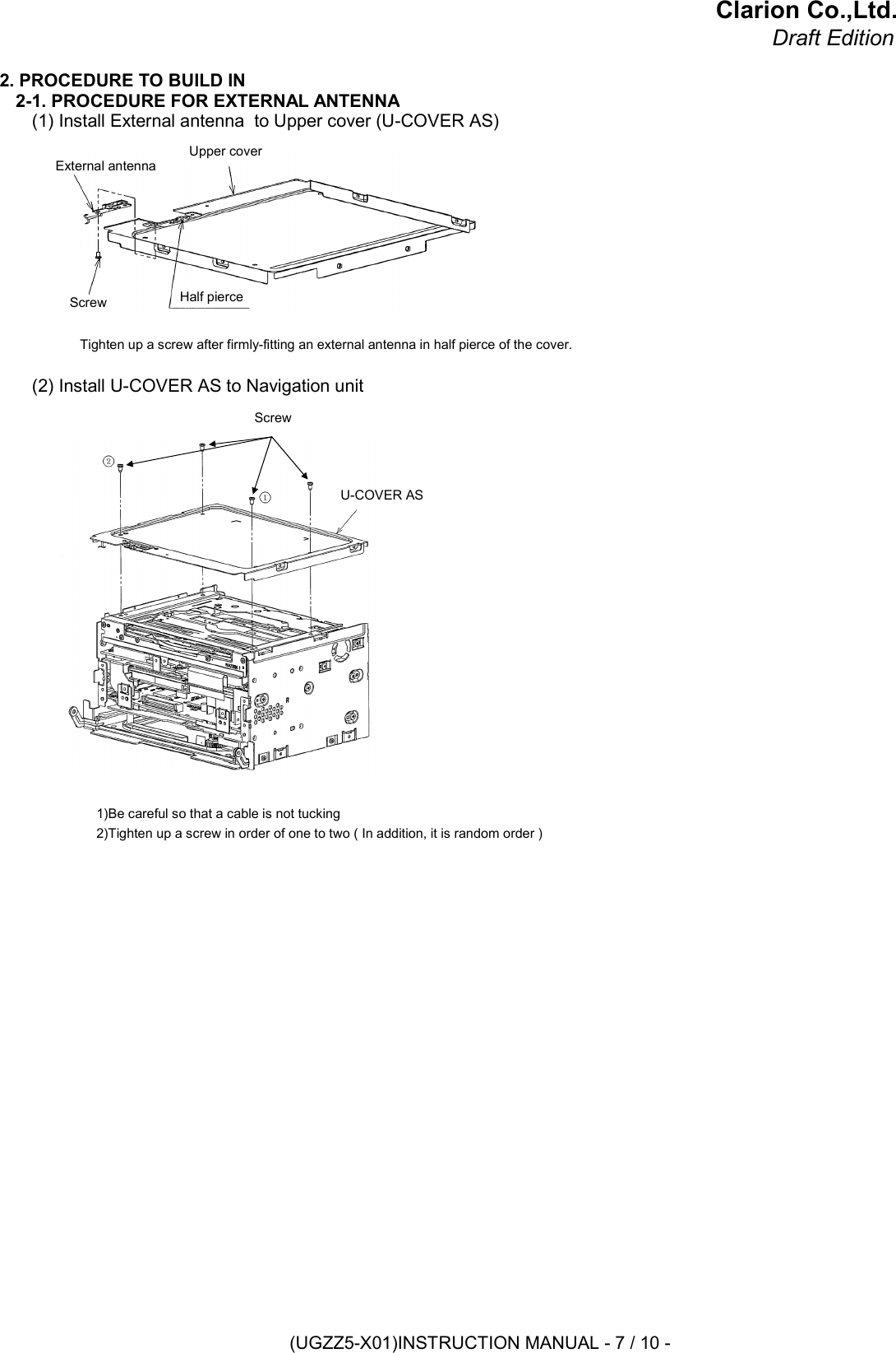
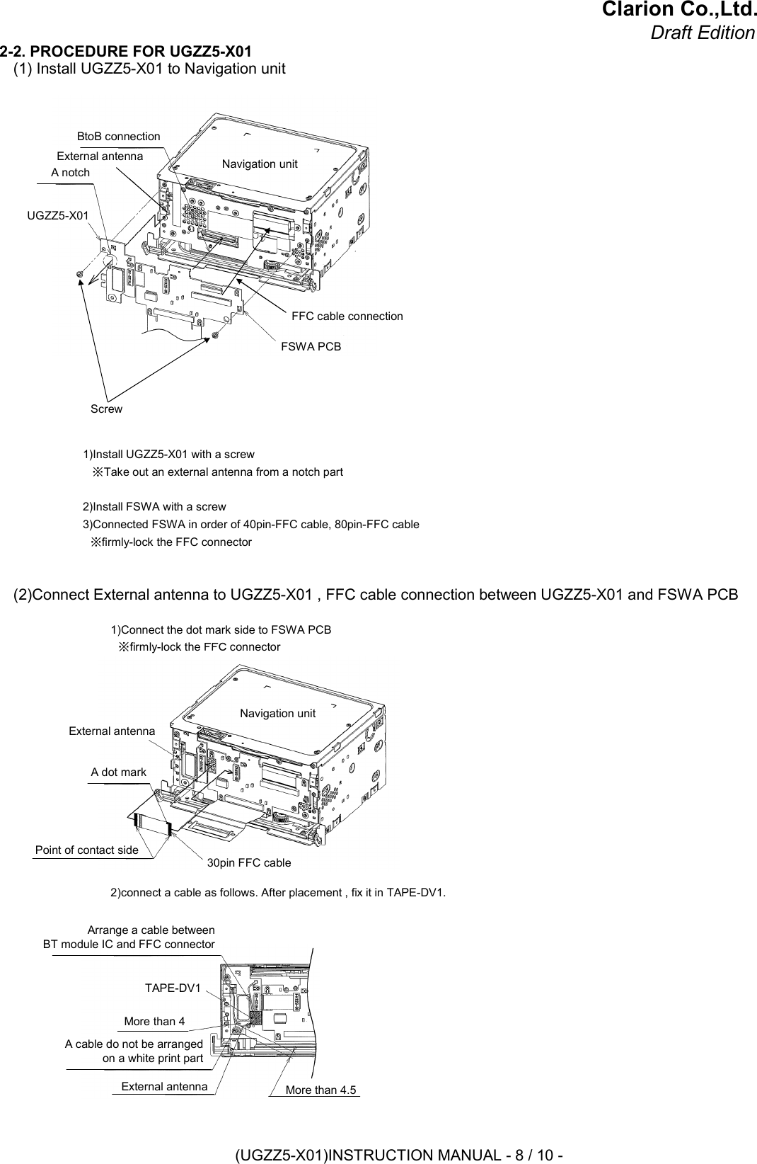
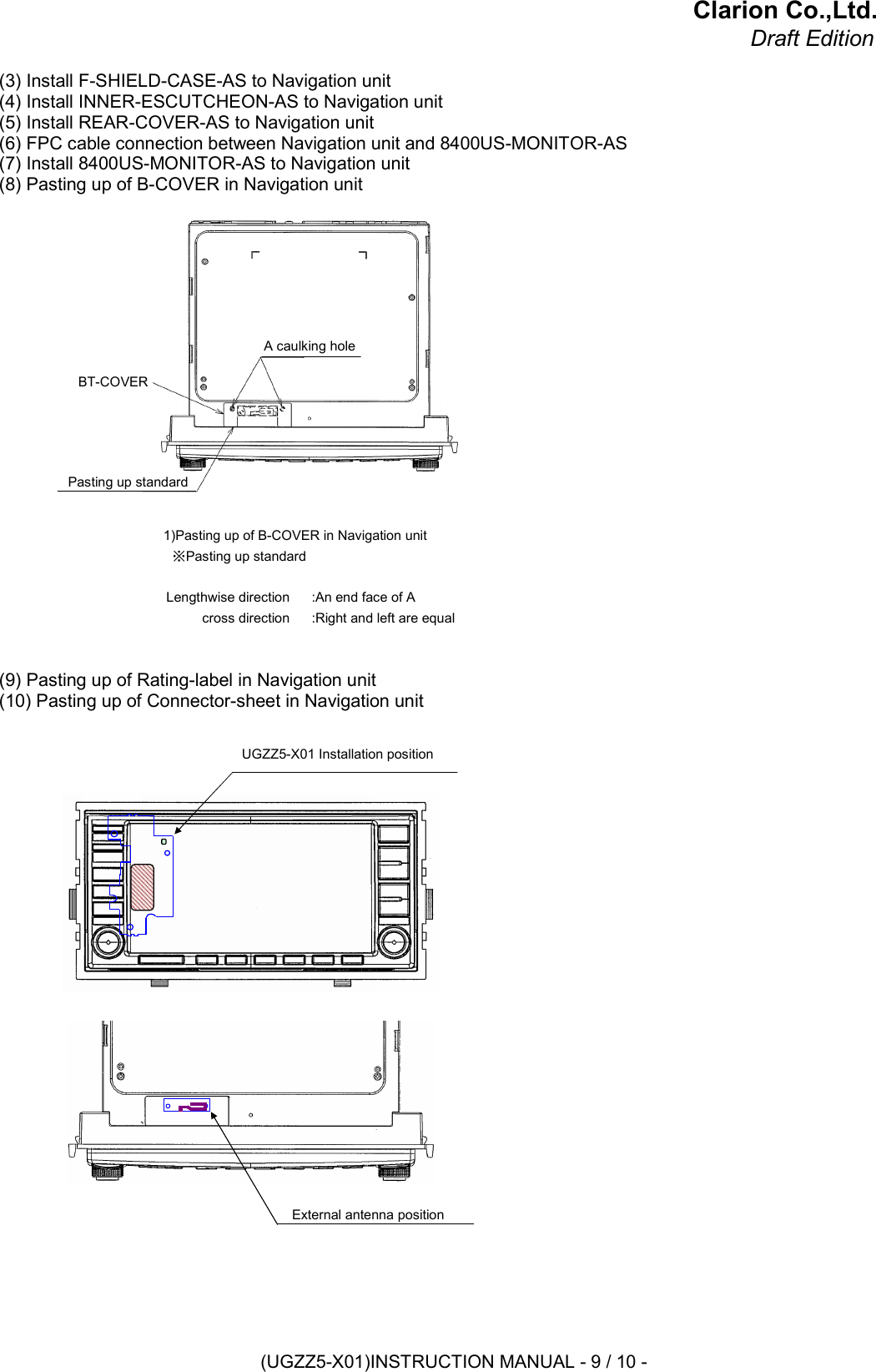
![Clarion Co.,Ltd.Draft Edition1. BLUETOOTH MODULE SPECIFICATION1-1. PRODUCT NAMEUGZZ5-X011-2. MANUFACTUREALPS ELECTRIC1-3. FEATURESBluetooth™ Specification V2.0 supportComplete type of Bluetooth module,built in various profileBuilt-in Link controller, Link manager ProtocolOutput power class 2 compliantAn external antenna model (Antenna type is inverted-F antenna)Full custom package with pwb can be fit to onlyBluit-in Flash memory(8bit), system clock 26MHz(OSC)FFC cable interface1-4. SPECIFICATION1-4-1. MECHANICAL SPECIFICATION1-4-1-1. EXTERNAL DIMENSIONSRefer to the following page.SWALPS ELECTRICSKRPABE010RF CONNECTORHIROSE ELECTRICU.FL-R-SMT-1[15]ON-BOARD RAG TERMINALKITAGAWA INDUSTRIESOG-RM26FLEXIBLE CABLECONNECTORHIROSE ELECTRICFH12A-30S-0.5SH(55)Bluetooth ModuleALPS ELECTRICUGZZ5-611BCONNECTORTERMINAL NO.Unit: [mm](UGZZ5-X01)INSTRUCTION MANUAL - 2 / 10 -](https://usermanual.wiki/Clarion/HGZ0036/User-Guide-1159179-Page-2.png)
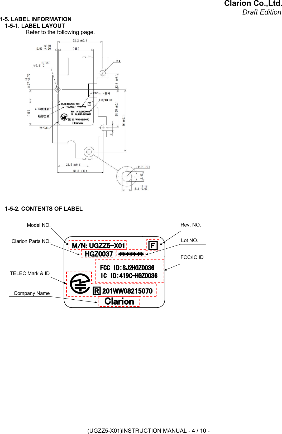
![Clarion Co.,Ltd.Draft Edition1-4-1-2. MASS10.6 [g]1-4-2. ELECTRICAL SPECIFICATION1-4-2-1. POWER SUPPLY VOLTAGEDC +3.1 to 3.5 [V]1-4-2-2. TEMPERATURE RANGE-30 to +85 [degree C]1-4-3. RF SPECIFICATION1-4-3-1. NORMAL TRANSMIT POWER ( AVERAGED POWER )-6 to +4 [dBm]1-4-3-2. REFERENCE SENSITIVITY LEVEL ( BER = 0.001% )MAX. -70 [dBm]1-4-4. EXTERNAL ANTENNA SPECIFICATION1-4-4-1. PRODUCT NAMEANT0791-16B/U-BT1-4-4-2. MANUFACTURENISSEI ELECTRIC1-4-4-3. ANTENNA TYPEInverted F1-4-4-4. AVERAGE GAIN-6.81 [dBi]1-4-4-5. PEAK GAINHorizontal : -3.1 [dBi]Vertical : -5.4 [dBi]1-4-4-6. EXTERNAL DIMENSIONS(UGZZ5-X01)INSTRUCTION MANUAL - 3 / 10 -](https://usermanual.wiki/Clarion/HGZ0036/User-Guide-1159179-Page-3.png)
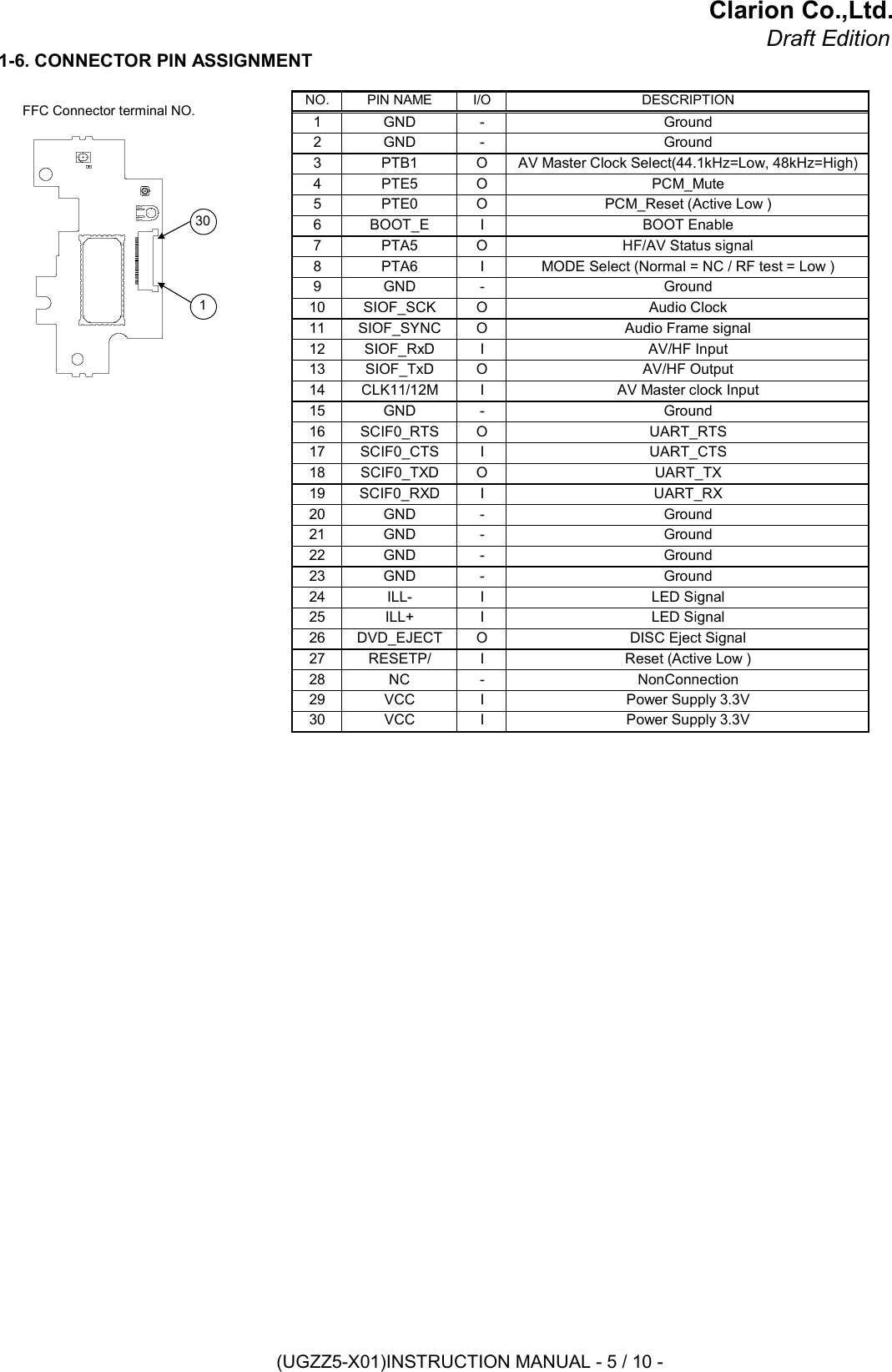
![Clarion Co.,Ltd.Draft Edition1-7. GND INFORMATIONGND PIN of MAJOR PARTS.・・・ GND AREA3 CN3 OG-RM26 ON-BOARD RAG TERMINAL -41,33,42,6,14,24,26,3647 IC3 TC7WH241FK LOGIC IC6 IC2 BD5225FVE RESET IC5 IC1 UGZZ5-X611B BLUETOOTH MODULE IC4 CM3 SKRPABE010 SWGND PIN NO.1,2,9,15,20,21,22,232 CN2 U.FL-SMT1[15] RF CONNECTOR1 CN1 FH12A-30S-0.5SH(55) FFC CONNECTORNO. REF. PARTS NAME DESCRIPTIONIC1CN1CN4CMCN2IC3IC2CONNECT TO FSWA PCB(NAVI BOARD)CONNECT TO CASEGND(UGZZ5-X01)INSTRUCTION MANUAL - 6 / 10 -](https://usermanual.wiki/Clarion/HGZ0036/User-Guide-1159179-Page-6.png)