Clarion HGZ0036 Car equipment unit User Manual Manual
Clarion Co., Ltd Car equipment unit Manual
Clarion >
Manual

Clarion Co.,Ltd.
Draft Edition
(UGZZ5-X01)INSTRUCTION MANUAL
Table of Contents
1. BLUETOOTH MODULE SPECIFICATION
1-1. PRODUCT NAME . . . . . . . . . . 2
1-2. MANUFACTURE . . . . . . . . . . 2
1-3. FEATURES . . . . . . . . . . 2
1-4. SPECIFICATION
1-4-1. MECHANICAL SPECIFICATION
1-4-1-1. EXTERNAL DIMENSIONS . . . . . . . . . . 2
1-4-1-2. MASS . . . . . . . . . . 2
1-4-2. ELECTRICAL SPECIFICATION
1-4-2-1. POWER SUPPLY VOLTAGE . . . . . . . . . . 2
1-4-2-2. TEMPERATURE RANGE . . . . . . . . . . 2
1-4-3. RF SPECIFICATION
1-4-3-1. NORMAL TRANSMIT POWER ( AVERAGED POWER ) . . . . . . . . . . 2
1-4-3-2. REFERENCE SENSITIVITY LEVEL ( BER = 0.001% ) . . . . . . . . . . 2
1-4-4. EXTERNAL ANTENNA SPECIFICATION
1-4-4-1. PRODUCT NAME . . . . . . . . . . 3
1-4-4-2. MANUFACTURE . . . . . . . . . . 3
1-4-4-3. ANTENNA TYPE . . . . . . . . . . 3
1-4-4-4. AVERAGE GAIN . . . . . . . . . . 3
1-4-4-5. PEAK GAIN . . . . . . . . . . 3
1-4-4-6. EXTERNAL DIMENSIONS . . . . . . . . . . 3
1-5. LABEL INFORMATION
1-5-1. LABEL LAYOUT . . . . . . . . . . 3
1-5-2. CONTENTS OF LABEL . . . . . . . . . . 4
1-6. CONNECTOR PIN ASSIGNMENT . . . . . . . . . . 4
1-8. GND INFORMATION . . . . . . . . . . 5
2. PROCEDURE TO BUILD IN
2-1. PROCEDURE FOR EXTERNAL ANTENNA . . . . . . . . . . 6
2-2. PROCEDURE FOR UGZZ5-X01 . . . . . . . . . . 6
3. NOTICE . . . . . . . . . . 8
(UGZZ5-X01)INSTRUCTION MANUAL - 1 / 10 -
Clarion Co.,Ltd.
Draft Edition
1. BLUETOOTH MODULE SPECIFICATION
1-1. PRODUCT NAME
UGZZ5-X01
1-2. MANUFACTURE
ALPS ELECTRIC
1-3. FEATURES
Bluetooth™ Specification V2.0 support
Complete type of Bluetooth module,built in various profile
Built-in Link controller, Link manager Protocol
Output power class 2 compliant
An external antenna model (Antenna type is inverted-F antenna)
Full custom package with pwb can be fit to only
Bluit-in Flash memory(8bit), system clock 26MHz(OSC)
FFC cable interface
1-4. SPECIFICATION
1-4-1. MECHANICAL SPECIFICATION
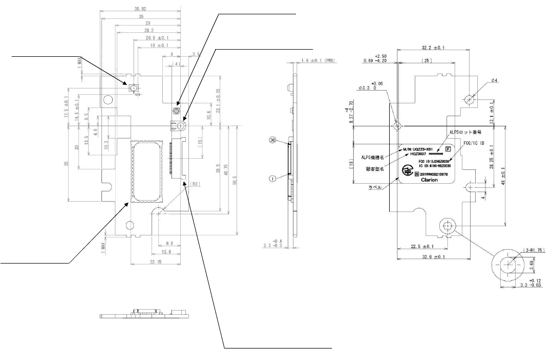
1-4-1-1. EXTERNAL DIMENSIONS
Refer to the following page.
SW
ALPS ELECTRIC
SKRPABE010
RF CONNECTOR
HIROSE ELECTRIC
U.FL-R-SMT-1[15]
ON-BOARD RAG TERMINAL
KITAGAWA INDUSTRIES
OG-RM26
FLEXIBLE CABLE
CONNECTOR
HIROSE ELECTRIC
FH12A-30S-0.5SH(55)
Bluetooth Module
ALPS ELECTRIC
UGZZ5-611B
CONNECTOR
TERMINAL NO.
Unit: [mm]
(UGZZ5-X01)INSTRUCTION MANUAL - 2 / 10 -
Clarion Co.,Ltd.
Draft Edition
1-4-1-2. MASS
10.6 [g]
1-4-2. ELECTRICAL SPECIFICATION
1-4-2-1. POWER SUPPLY VOLTAGE
DC +3.1 to 3.5 [V]
1-4-2-2. TEMPERATURE RANGE
-30 to +85 [degree C]
1-4-3. RF SPECIFICATION
1-4-3-1. NORMAL TRANSMIT POWER ( AVERAGED POWER )
-6 to +4 [dBm]
1-4-3-2. REFERENCE SENSITIVITY LEVEL ( BER = 0.001% )
MAX. -70 [dBm]
1-4-4. EXTERNAL ANTENNA SPECIFICATION
1-4-4-1. PRODUCT NAME
ANT0791-16B/U-BT
1-4-4-2. MANUFACTURE
NISSEI ELECTRIC
1-4-4-3. ANTENNA TYPE
Inverted F
1-4-4-4. AVERAGE GAIN
-6.81 [dBi]
1-4-4-5. PEAK GAIN
Horizontal : -3.1 [dBi]
Vertical : -5.4 [dBi]
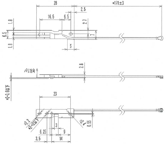
1-4-4-6. EXTERNAL DIMENSIONS
(UGZZ5-X01)INSTRUCTION MANUAL - 3 / 10 -
Clarion Co.,Ltd.
Draft Edition
1-5. LABEL INFORMATION
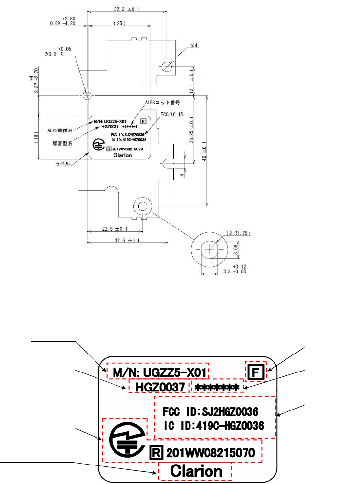
1-5-1. LABEL LAYOUT
Refer to the following page.
1-5-2. CONTENTS OF LABEL
Model NO.
Clarion Parts NO.
TELEC Mark & ID
Company Name
Rev. NO.
Lot NO.
FCC/IC ID
(UGZZ5-X01)INSTRUCTION MANUAL - 4 / 10 -
Clarion Co.,Ltd.
Draft Edition
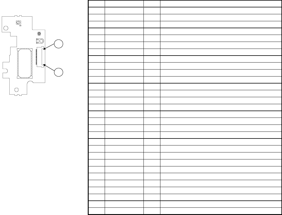
1-6. CONNECTOR PIN ASSIGNMENT
Reset (Active Low )
Power Supply 3.3V
Ground
Ground
Ground
Ground
Ground
Ground
Ground
AV Master clock Input
UART_RX
UART_TX
Audio Clock
AV/HF Input
AV/HF Output
UART_RTS
UART_CTS
AV Master Clock Select(44.1kHz=Low, 48kHz=High)
PCM_Reset (Active Low )
HF/AV Status signal
Audio Frame signal
MODE Select (Normal = NC / RF test = Low )
BOOT Enable
PCM_Mute
I
I
Power Supply 3.3V
Ground
LED Signal
LED Signal
DISC Eject Signal
NonConnection
I
O
I
-
-
-
-
I
VCC
VCC
-
-
O
O
O
I
O
I
ILL+
DVD_EJECT
RESETP/
NC
GND
GND
GND
ILL-
29
30
GND
GND
PTB1
PTE5
PTE0
BOOT_E
PTA5
PTA6
25
26
27
28
21
22
23
24
20 GND -
19 SCIF0_RXD I
18 SCIF0_TXD O
17 SCIF0_CTS I
16 SCIF0_RTS O
15 GND -
14 CLK11/12M I
13 SIOF_TxD O
12 SIOF_RxD I
11 SIOF_SYNC O
10 SIOF_SCK O
9 GND -
8
7
6
5
4
3
2
1
NO. I/O DESCRIPTIONPIN NAME
30
1
FFC Connector terminal NO.
(UGZZ5-X01)INSTRUCTION MANUAL - 5 / 10 -
Clarion Co.,Ltd.
Draft Edition
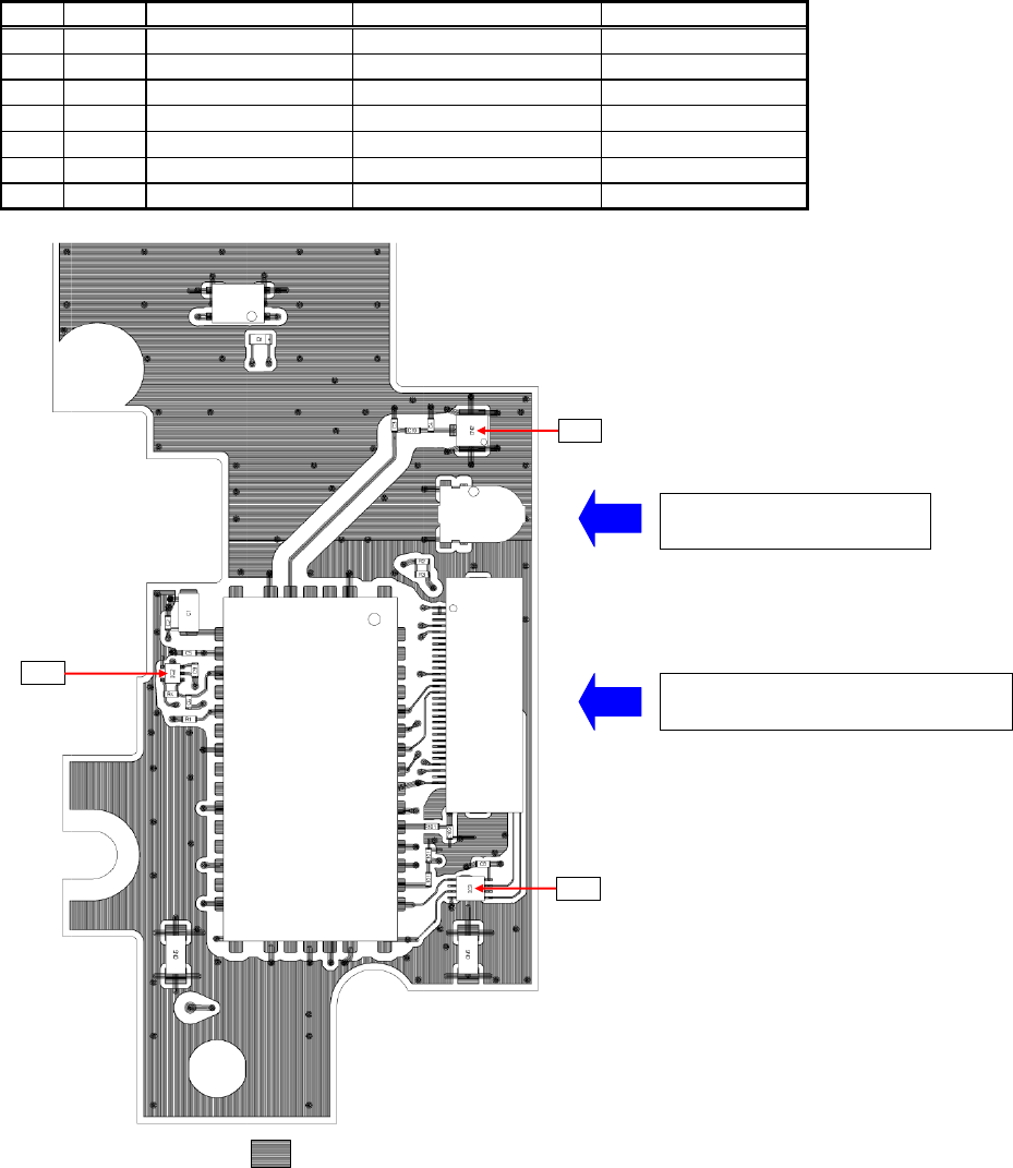
1-7. GND INFORMATION
GND PIN of MAJOR PARTS.
・・・ GND AREA
3 CN3 OG-RM26 ON-BOARD RAG TERMINAL -
4
1,3
3,4
2,6,14,24,26,36
4
7 IC3 TC7WH241FK LOGIC IC
6 IC2 BD5225FVE RESET IC
5 IC1 UGZZ5-X611B BLUETOOTH MODULE IC
4 CM3 SKRPABE010 SW
GND PIN NO.
1,2,9,15,20,21,22,23
2 CN2 U.FL-SMT1[15] RF CONNECTOR
1 CN1 FH12A-30S-0.5SH(55) FFC CONNECTOR
NO. REF. PARTS NAME DESCRIPTION
IC1
CN1
CN4
CM
CN2
IC3
IC2
CONNECT TO FSWA PCB
(NAVI BOARD)
CONNECT TO CASE
GND
(UGZZ5-X01)INSTRUCTION MANUAL - 6 / 10 -
Clarion Co.,Ltd.
Draft Edition
2. PROCEDURE TO BUILD IN
2-1. PROCEDURE FOR EXTERNAL ANTENNA
(1) Install External antenna to Upper cover (U-COVER AS)
Tighten up a screw after firmly-fitting an external antenna in half pierce of the cover.
(2) Install U-COVER AS to Navigation unit
1)Be careful so that a cable is not tucking
2)Tighten up a screw in order of one to two ( In addition, it is random order )
Upper cover
External antenna
Screw Half pierce
Screw
U-COVER AS
(UGZZ5-X01)INSTRUCTION MANUAL - 7 / 10 -
Clarion Co.,Ltd.
Draft Edition
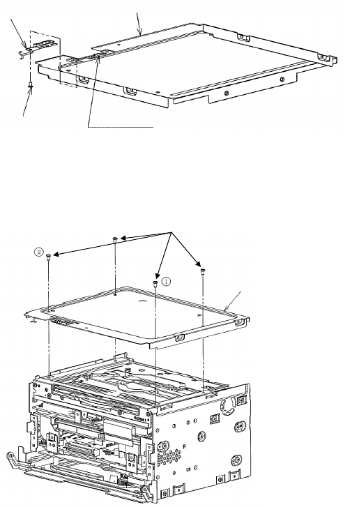
2-2. PROCEDURE FOR UGZZ5-X01
(1) Install UGZZ5-X01 to Navigation unit
1)Install UGZZ5-X01 with a screw
※Take out an external antenna from a notch part
2)Install FSWA with a screw
3)Connected FSWA in order of 40pin-FFC cable, 80pin-FFC cable
※firmly-lock the FFC connector
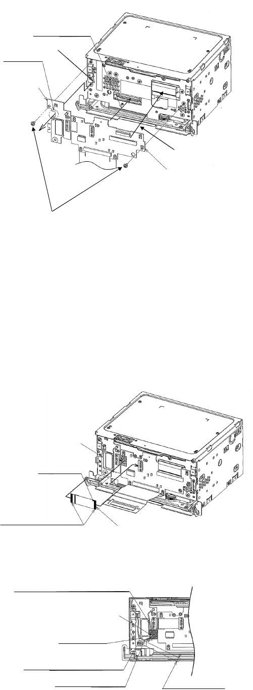
(2)Connect External antenna to UGZZ5-X01 , FFC cable connection between UGZZ5-X01 and FSWA PCB
1)Connect the dot mark side to FSWA PCB
※firmly-lock the FFC connector
2)connect a cable as follows. After placement , fix it in TAPE-DV1.
BtoB connection
External antenna
A notch
UGZZ5-X01
FSWA PCB
Navigation unit
FFC cable connection
Screw
Navigation unit
External antenna
A dot mark
Point of contact side 30pin FFC cable
Arrange a cable between
BT module IC and FFC connector
TAPE-DV1
More than 4
More than 4.5
External antenna
A cable do not be arranged
on a white print part
(UGZZ5-X01)INSTRUCTION MANUAL - 8 / 10 -
Clarion Co.,Ltd.
Draft Edition
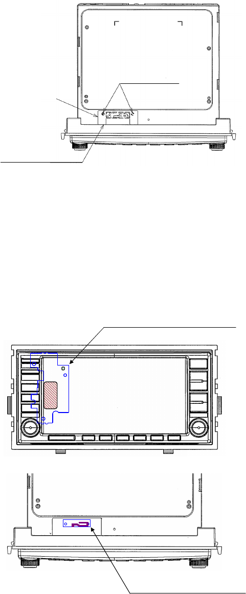
(3) Install F-SHIELD-CASE-AS to Navigation unit
(4) Install INNER-ESCUTCHEON-AS to Navigation unit
(5) Install REAR-COVER-AS to Navigation unit
(6) FPC cable connection between Navigation unit and 8400US-MONITOR-AS
(7) Install 8400US-MONITOR-AS to Navigation unit
(8) Pasting up of B-COVER in Navigation unit
1)Pasting up of B-COVER in Navigation unit
※Pasting up standard
Lengthwise direction :An end face of A
cross direction :Right and left are equal
(9) Pasting up of Rating-label in Navigation unit
(10) Pasting up of Connector-sheet in Navigation unit
BT-COVER
Pasting up standard
A caulking hole
UGZZ5-X01 Installation position
External antenna position
(UGZZ5-X01)INSTRUCTION MANUAL - 9 / 10 -
Clarion Co.,Ltd.
Draft Edition
3. NOTICE
-Operation is subject to the following two conditions:
(1) this device may not cause interference, and
(2) this device must accept any interference, including interference that may cause undesired operation of the device.
-Any changes or modifications not expressly approved by the party responsible for compliance could void
the user's authority to operate the equipment.
-Please note that this users manual should not be provided to end-users.
-The following sentence has to be displayed on the outside of the device in which the module is installed:
"Contains Transmitter Module FCC ID: SJ2HGZ0036", or "Contains FCC ID: SJ2HGZ0036"
-This equipment complies with FCC RF radiation exposure limits set forth for an uncontrolled environment.
-The antenna used for this transmitter must not be co-located or operating in conjunction with any other antenna or
transmitter.
(UGZZ5-X01)INSTRUCTION MANUAL - 10 / 10 -