Clipcomm EDR-AP Bluetooth Access Point User Manual
Clipcomm, Inc. Bluetooth Access Point Users Manual
UserManual.wiki
>
Clipcomm
>
EDR AP User Manual
Users Manual
Navigation menu
Upload a User Manual
Namespaces
Wiki Guide
HTML
PDF
Info
Views
User Manual
Discussion / Help
Navigation
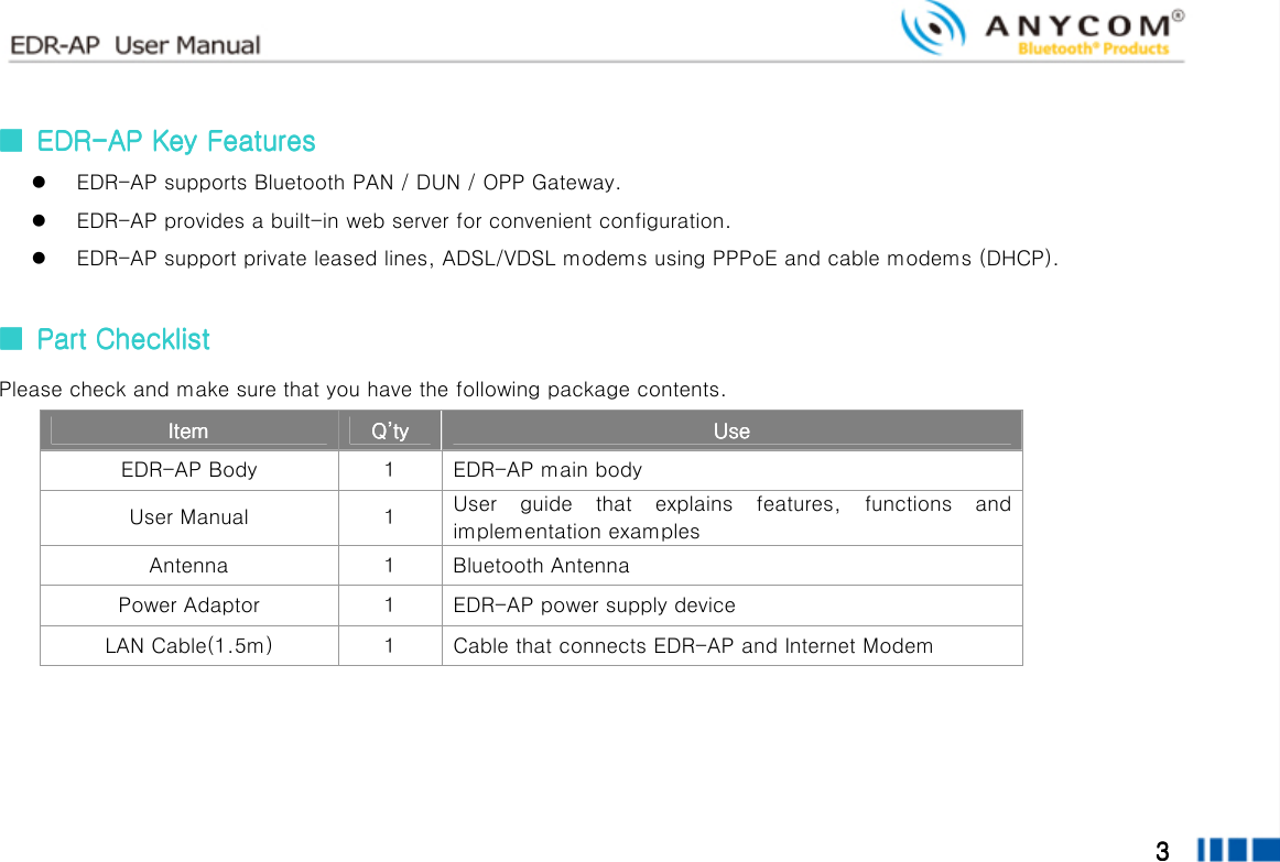
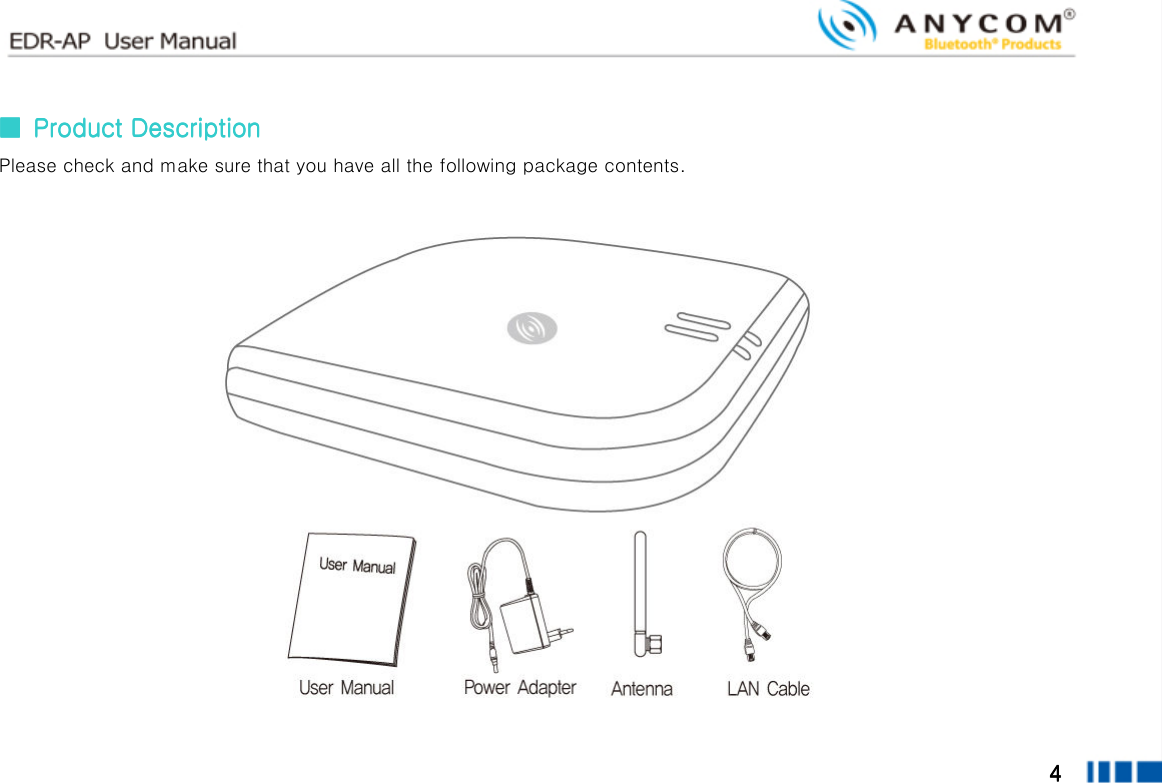
![2222 ■■■■ Table of ContentsTable of ContentsTable of ContentsTable of Contents 1. EDR-AP KEY FEATURES 2. PART CHECKLIST 3. PRODUCT DESCRIPTION 4. SPECIFICATION 5. CONTROLS AND FUNCTIONS [BUTTON/LED/REAR PANEL] 6. EDR-AP INSTALLATION 7. CAUTION 8. ETHERNET NETWORK CONNECTION](https://usermanual.wiki/Clipcomm/EDR-AP/User-Guide-751294-Page-2.png)

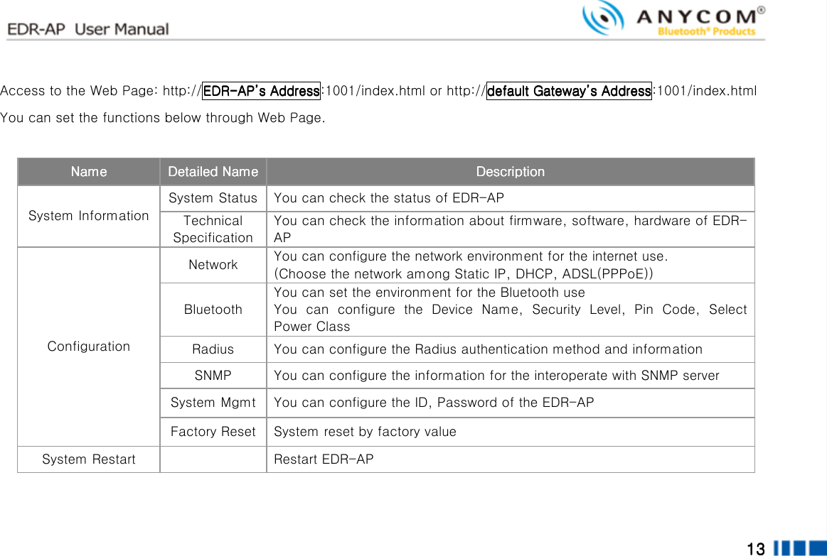
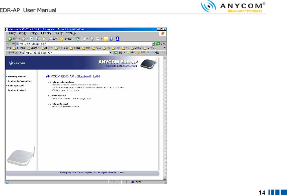
![12121212 ■■■■ Configuration using Configuration using Configuration using Configuration using Web InterfaceWeb InterfaceWeb InterfaceWeb Interface You can use Web Interface with web browser in order to set the EDR-AP configuration. You can access the Web Interface by IP address or Bluetooth connection (PAN). For the access by Bluetooth connection, connect with PAN of EDR-AP and access with Gateway address assigned from the PC. ▌▌▌▌ Checking deviceChecking deviceChecking deviceChecking device’’’’s IP addresss IP addresss IP addresss IP address In case of you don’t know the IP address, you can check the current EDR-AP IP address by configuring IP address of user’s PC. ① Click [Start] from the bottom menu bar, then choose [Settings]. ② Select [Control Panel] to view a new window, and then choose [Network connections]. ③ Right click on [Local Area Connection]. If there are more than one Local Area Connections, choose the one that is currently in use. ④ Choose [Properties] when a new window appears. ⑤ Click [IP Address] tab and then check the [Obtain an IP address automatically] box. If the box is already checked, you don’t need to change anything. ⑥ Click [Ok]. You don’t need to restart your computer in Windows XP.](https://usermanual.wiki/Clipcomm/EDR-AP/User-Guide-751294-Page-12.png)
![15151515 ▌▌▌▌ Network ConfigurationNetwork ConfigurationNetwork ConfigurationNetwork Configuration ① Select [Configuration], and then choose [Network] to enter the network configuration page. ② Now select and set the appropriate IP configuration parameters that match your network environment from below. (a) Static IP i. Select [Static IP]. ii. Enter the IP, gateway, network mask and DNS address for EDR-AP. (b) DHCP(Dynamic IP) or Cable modem i. Select [DHCP]. (c) ADSL(PPPoE) i. Select [ADSL]. ii. Enter ADSL ID and the password.](https://usermanual.wiki/Clipcomm/EDR-AP/User-Guide-751294-Page-15.png)
![16161616 ▌▌▌▌ Bluetooth ConfigurationBluetooth ConfigurationBluetooth ConfigurationBluetooth Configuration ① Select [Configuration], and then choose [Bluetooth] to enter the network configuration page. ② When the pop up window requesting ID and Password, type USER ID: admin, Password: 0000. TitleTitleTitleTitle DescriptionDescriptionDescriptionDescription Default Default Default Default ValueValueValueValue Device Name Means the name of the device. Choose the “User Defined” and type the name you wish. Use Default Security Configuration Set the Security Level. Level 1 : Security Code(Pin Code) Is not requested. Level 3 : Security Code(Pin Code) Is requested. Level 3 Device Configuration Type the Pin Code of EDR-AP. 000000 Radio Power Class Select the electric wave of EDR-AP. Class 1 is the strongest electric wave. Class 1](https://usermanual.wiki/Clipcomm/EDR-AP/User-Guide-751294-Page-16.png)
![17171717 ▌▌▌▌ RADIUS RADIUS RADIUS RADIUS ① Select [Configuration], and then choose [RADIUS] to enter the network configuration page. TitleTitleTitleTitle DescriptionDescriptionDescriptionDescription Default Default Default Default valuevaluevaluevalue Retransmission Define the number of re-transmission times in case of data failures when interoperate with Radius server. 1 Timeout(sec) Set the time interval for Retransmission. 5 sec Authentication Server Set the domain or IP address of Radius Server. Authentication Password Set the Password to receive the authentication from the Radius Server. Authentication Port Number Set the Port Number of Radius Server. 1812](https://usermanual.wiki/Clipcomm/EDR-AP/User-Guide-751294-Page-17.png)
![18181818 ▌▌▌▌ SNMPSNMPSNMPSNMP ① Select [Configuration], and then choose [SNMP] to enter the network configuration page. TitleTitleTitleTitle DescriptionDescriptionDescriptionDescription Default Default Default Default VVVValuealuealuealue SNMP activation Activate the SNMP function. enable SNMP Accessibility Check the weather or not to be accessed to the SNMP Server. Use SNMP GET/SET Server Setting Set the domain or IP address of SNMP Server. SNMP Community Setting Set the authority for Read/Write of SNMP Server interoperate. RD : Public WR : private](https://usermanual.wiki/Clipcomm/EDR-AP/User-Guide-751294-Page-18.png)