Clipcomm EDR-AP Bluetooth Access Point User Manual
Clipcomm, Inc. Bluetooth Access Point Users Manual
Clipcomm >
Users Manual
1
11
1

2
22
2
■
■■
■
Table of Contents
Table of ContentsTable of Contents
Table of Contents
1. EDR-AP KEY FEATURES
2. PART CHECKLIST
3. PRODUCT DESCRIPTION
4. SPECIFICATION
5. CONTROLS AND FUNCTIONS [BUTTON/LED/REAR PANEL]
6. EDR-AP INSTALLATION
7. CAUTION
8. ETHERNET NETWORK CONNECTION
3
33
3
■
■■
■
EDR
EDREDR
EDR-
--
-AP Key Features
AP Key FeaturesAP Key Features
AP Key Features
EDR-AP supports Bluetooth PAN / DUN / OPP Gateway.
EDR-AP provides a built-in web server for convenient configuration.
EDR-AP support private leased lines, ADSL/VDSL modems using PPPoE and cable modems (DHCP).
■
■■
■
Part Checklist
Part ChecklistPart Checklist
Part Checklist
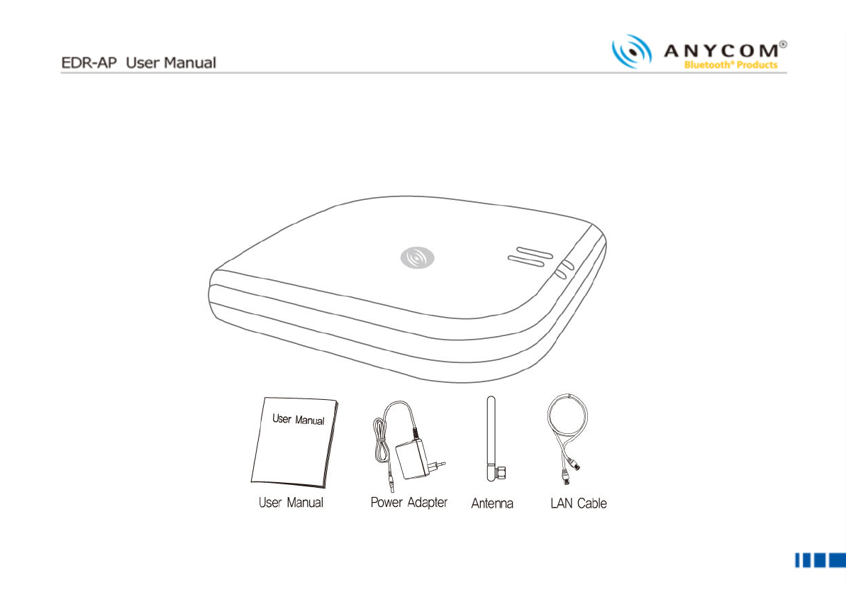
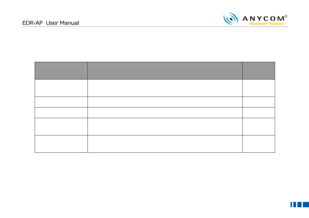
Please check and make sure that you have the following package contents.
I
II
Item
temtem
tem
Q
QQ
Q’
’’
’ty
tyty
ty
Use
UseUse
Use
EDR-AP Body 1 EDR-AP main body
User Manual 1 User guide that explains features, functions and
implementation examples
Antenna 1 Bluetooth Antenna
Power Adaptor 1 EDR-AP power supply device
LAN Cable(1.5m) 1 Cable that connects EDR-AP and Internet Modem
4
44
4
■
■■
■
Product Description
Product DescriptionProduct Description
Product Description
Please check and make sure that you have all the following package contents.

5
55
5
■
■■
■ Specification
Specification Specification
Specification
Name
Name Name
Name
Description
DescriptionDescription
Description
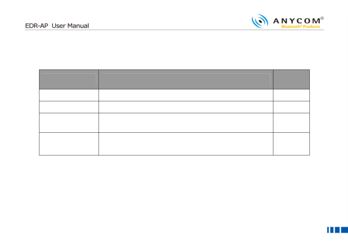
Output Power 15 ~ 20 dBm
Rx Sensitivity 85 dBm
Channel 79 CH
Antenna 2.4GHz Band 1/2λSleeve Dipole Antenna
Frequency 2402 ~ 2480 MHz
Modulation FSK, QPSK
Adaptor 5V 1A
Max Current 560mA
Operating
Temperature
-20℃~55℃
6
66
6
■
■■
■
Controls and Functions
Controls and FunctionsControls and Functions
Controls and Functions
▌
▌▌
▌
Button
ButtonButton
Button
Name
NameName
Name
Description
DescriptionDescription
Description
Button If you press any two buttons on the unit, the LED (Green) blinks and EDR-AP goes to
discoverable and pairable mode.
7
77
7
▌
▌▌
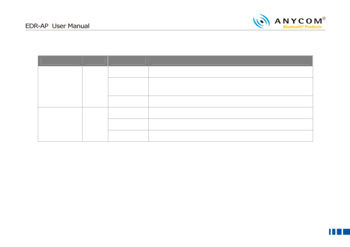
▌LEDs
LEDsLEDs
LEDs
Name
NameName
Name
Color
ColorColor
Color
Status
StatusStatus
Status
Description
DescriptionDescription
Description
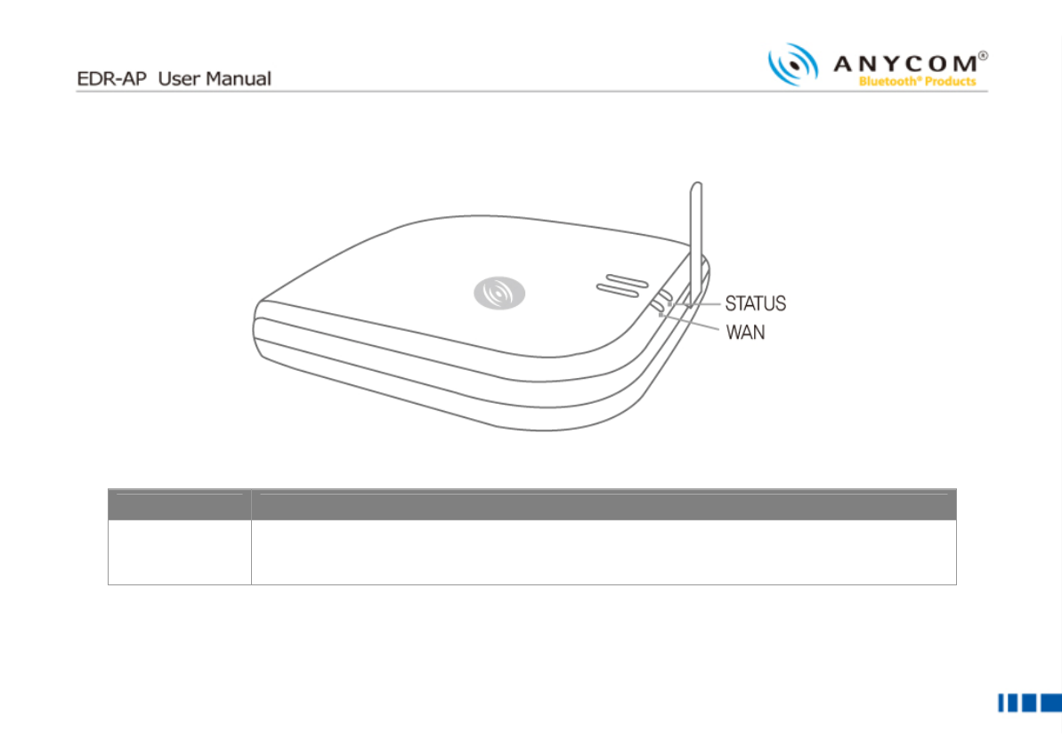
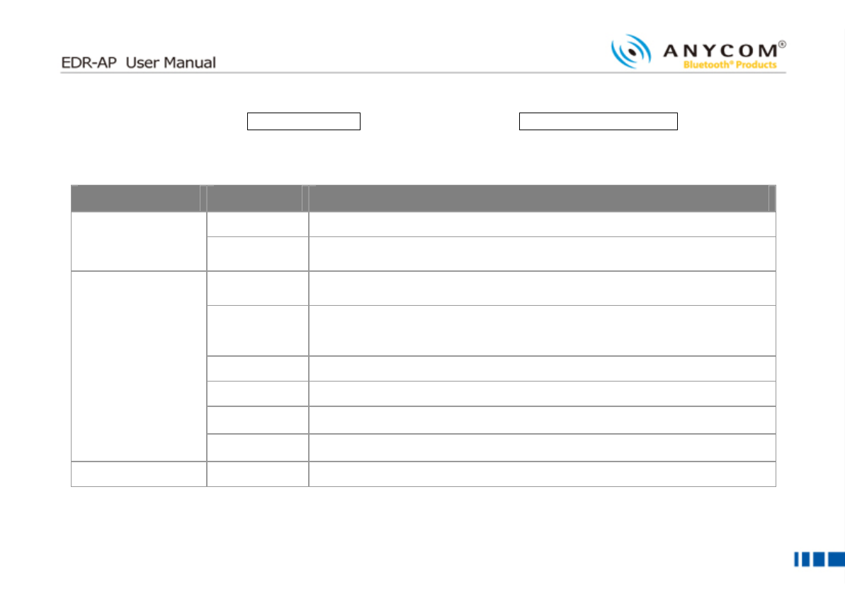
ON Power is ON and Bluetooth is normal state mode
BLINK Other device is connected and new device is under pairable
mode
STATUS Green
OFF Power is OFF or Bluetooth is abnormal state mode
ON TCP/IP communication is able mode
BLINK TCP/IP communication is disable mode
WAN Green
OFF No connection with the Ethernet
* When EDR-AP restarts, every LED blinks several times
8
88
8
▌
▌▌
▌
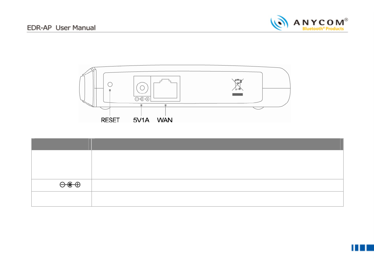
Rear Panel
Rear PanelRear Panel
Rear Panel
(From the left to the right side)
Name
NameName
Name
Description
DescriptionDescription
Description
RESET
Press this button for more than three seconds to restore the original factory default setting of
EDR-AP
(Reboot: press between 1~3 seconds)
5V1A Connect the Power Adaptor
WAN Connect to private leased line, ADSL/VDSL modem, cable model using LAN cable (UTP
Cable)
9
99
9
■
■■
■
EDR
EDREDR
EDR-
--
-AP Installation
AP InstallationAP Installation
AP Installation
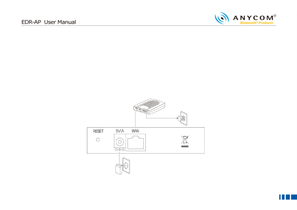
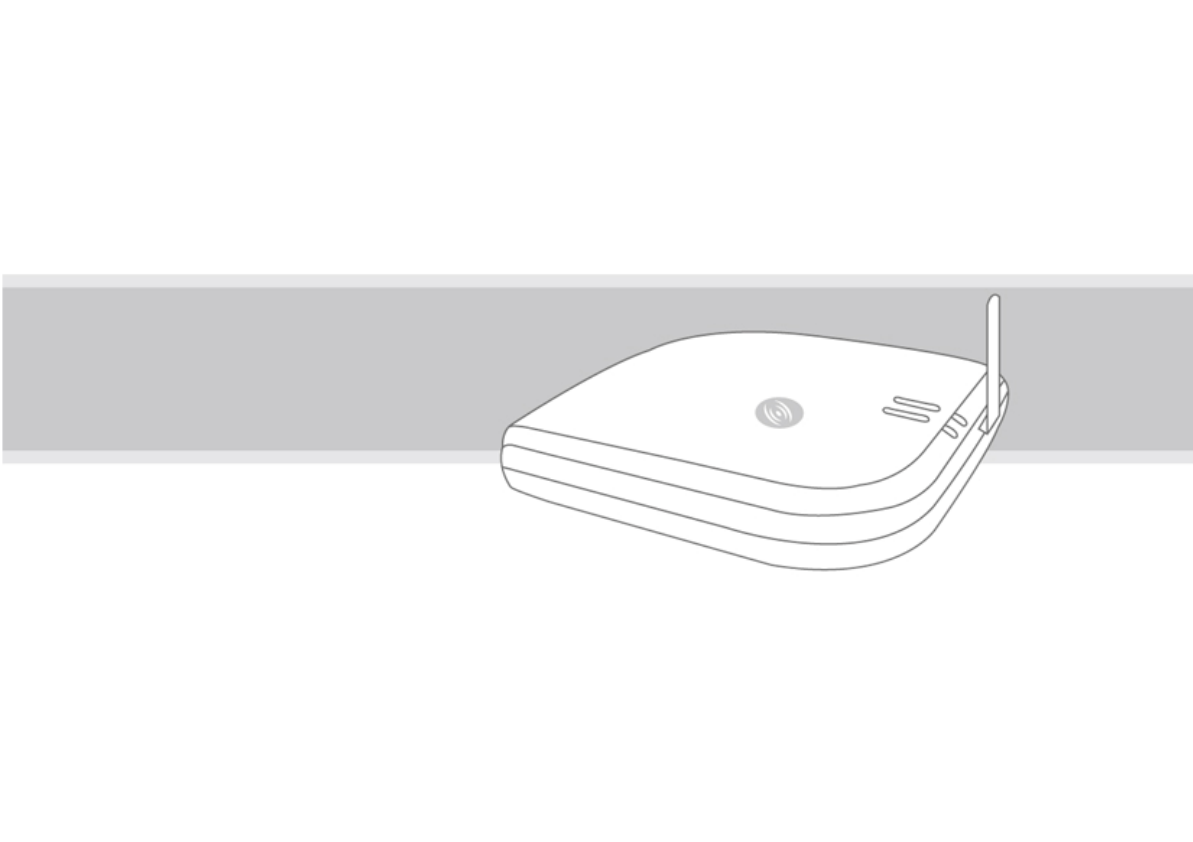
Please check the port location of the rear panel and then follow the steps below to install the BS-P100 properly.
▌
▌▌
▌
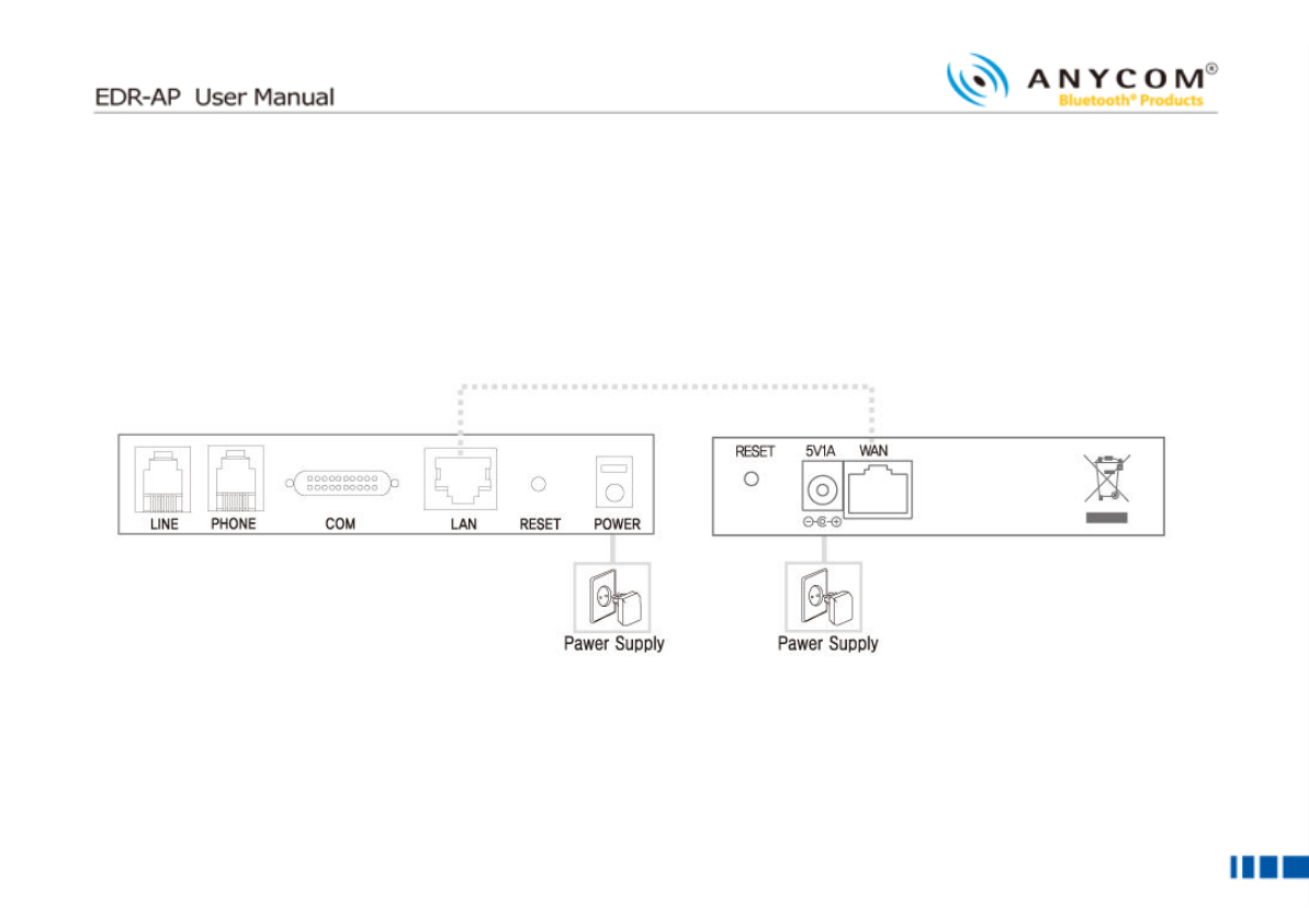
Ethernet Network Connection
Ethernet Network ConnectionEthernet Network Connection
Ethernet Network Connection
Let’s check the network cable connection to use the internet service.
Modem
10
1010
10
① Pull out the cable from the Ethernet (LAN) port of modem and connect it to the WAN port at the EDR-AP’s rear
panel.
② Connect the power adaptor to the “POWER” port at the EDR-AP rear panel.
③ Connect antenna provided to antenna connecting jack at the side of body. When you connect antenna, twist it on
carefully and lastly push it strongly.
11
1111
11
■
■■
■
CAUTION
CAUTIONCAUTION
CAUTION
Use only the power adaptor supplied. Using other power adaptors may cause the voice quality to deteriorate and
malfunction.
Install EDR-AP far from wireless LAN/microwave about 1m. If installed close may cause jamming.
Use only the antenna provided.
The data of this device could be lost When the static electricity occurs in antenna portion

12
1212
12
■
■■
■
Configuration using
Configuration using Configuration using
Configuration using Web Interface
Web InterfaceWeb Interface
Web Interface
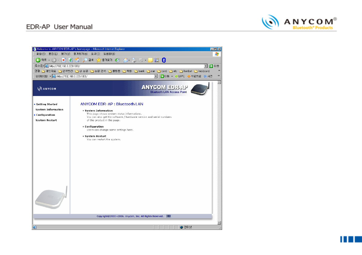
You can use Web Interface with web browser in order to set the EDR-AP configuration. You can access the Web
Interface by IP address or Bluetooth connection (PAN). For the access by Bluetooth connection, connect with PAN of
EDR-AP and access with Gateway address assigned from the PC.
▌
▌▌
▌
Checking device
Checking deviceChecking device
Checking device’
’’
’s IP address
s IP addresss IP address
s IP address
In case of you don’t know the IP address, you can check the current EDR-AP IP address by configuring IP address of
user’s PC.
① Click [Start] from the bottom menu bar, then choose [Settings].
② Select [Control Panel] to view a new window, and then choose [Network connections].
③ Right click on [Local Area Connection]. If there are more than one Local Area Connections, choose the one that
is currently in use.
④ Choose [Properties] when a new window appears.
⑤ Click [IP Address] tab and then check the [Obtain an IP address automatically] box. If the box is already checked,
you don’t need to change anything.
⑥ Click [Ok]. You don’t need to restart your computer in Windows XP.
13
1313
13
Access to the Web Page: http://EDR
EDREDR
EDR-
--
-AP
APAP
AP’
’’
’s
ss
s
Address
AddressAddress
Address:1001/index.html or http://default
defaultdefault
default
Gateway
GatewayGateway
Gateway’
’’
’s
ss
s
Address
AddressAddress
Address:1001/index.html
You can set the functions below through Web Page.
Name
NameName
Name
Detailed Name
Detailed NameDetailed Name
Detailed Name
Description
DescriptionDescription
Description
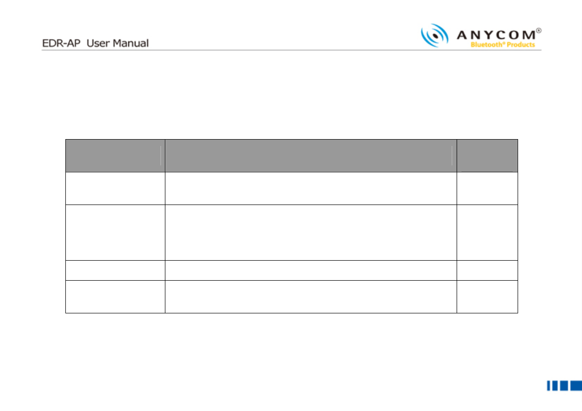
System Status
You can check the status of EDR-AP
System Information
Technical
Specification
You can check the information about firmware, software, hardware of EDR-
AP
Network You can configure the network environment for the internet use.
(Choose the network among Static IP, DHCP, ADSL(PPPoE))
Bluetooth
You can set the environment for the Bluetooth use
You can configure the Device Name, Security Level, Pin Code, Select
Power Class
Radius You can configure the Radius authentication method and information
SNMP You can configure the information for the interoperate with SNMP server
System Mgmt
You can configure the ID, Password of the EDR-AP
Configuration
Factory Reset
System reset by factory value
System Restart Restart EDR-AP
14
1414
14

15
1515
15
▌
▌▌
▌
Network Configuration
Network ConfigurationNetwork Configuration
Network Configuration
① Select [Configuration], and then choose [Network] to enter the network configuration page.
② Now select and set the appropriate IP configuration parameters that match your network environment from below.
(a) Static IP
i. Select [Static IP].
ii. Enter the IP, gateway, network mask and DNS address for EDR-AP.
(b) DHCP(Dynamic IP) or Cable modem
i. Select [DHCP].
(c) ADSL(PPPoE)
i. Select [ADSL].
ii. Enter ADSL ID and the password.
16
1616
16
▌
▌▌
▌
Bluetooth Configuration
Bluetooth ConfigurationBluetooth Configuration
Bluetooth Configuration
① Select [Configuration], and then choose [Bluetooth] to enter the network configuration page.
② When the pop up window requesting ID and Password, type USER ID: admin, Password: 0000.
Title
TitleTitle
Title
Description
DescriptionDescription
Description
Default
Default Default
Default
Value
ValueValue
Value
Device Name Means the name of the device. Choose the “User Defined” and
type the name you wish. Use Default
Security Configuration
Set the Security Level.
Level 1 : Security Code(Pin Code) Is not requested.
Level 3 : Security Code(Pin Code) Is requested.
Level 3
Device Configuration
Type the Pin Code of EDR-AP. 000000
Radio Power Class Select the electric wave of EDR-AP. Class 1 is the strongest
electric wave. Class 1
17
1717
17
▌
▌▌
▌ RADIUS
RADIUS RADIUS
RADIUS
① Select [Configuration], and then choose [RADIUS] to enter the network configuration page.
Title
TitleTitle
Title
Description
DescriptionDescription
Description
Default
Default Default
Default
value
valuevalue
value
Retransmission Define the number of re-transmission times in case of data
failures when interoperate with Radius server. 1
Timeout(sec) Set the time interval for Retransmission. 5 sec
Authentication Server
Set the domain or IP address of Radius Server.
Authentication
Password
Set the Password to receive the authentication from the Radius
Server.
Authentication Port
Number Set the Port Number of Radius Server. 1812
18
1818
18
▌
▌▌
▌
SNMP
SNMPSNMP
SNMP
① Select [Configuration], and then choose [SNMP] to enter the network configuration page.
Title
TitleTitle
Title
Description
DescriptionDescription
Description
Default
Default Default
Default
V
VV
Value
aluealue
alue
SNMP activation Activate the SNMP function. enable
SNMP Accessibility Check the weather or not to be accessed to the SNMP Server. Use
SNMP GET/SET
Server Setting Set the domain or IP address of SNMP Server.
SNMP Community
Setting Set the authority for Read/Write of SNMP Server interoperate.
RD : Public
WR : private

19
1919
19
This device complies with Part 15 of the FCC Rules. Operation is subject to the following two conditions: (1) this device
may not cause harmful interference, and (2) this device must accept any interference received, including interference that
may cause undesired operation.
CAUTION: Changes or modifications not expressly approved by the party responsible for compliance could void the user's
authority to operate the equipment.
▌
▌▌
▌
NOTE:
NOTE:NOTE:
NOTE:
This equipment has been tested and found to comply with the limits for a Class B digital device, pursuant to Part 15 of
the FCC Rules. These limits are designed to provide reasonable protection against harmful interference in a residential
installation. This equipment generates, uses and can radiate radio frequency energy and, if not installed and used in
accordance with the instructions, may cause harmful interference to radio communications. However, there is no
guarantee that interference will not occur in a particular installation. If this equipment does cause harmful interference to
radio or television reception, which can be determined by turning the equipment off and on, the user is encouraged to
try to correct the interference by one or more of the following
▌
▌▌
▌ Measures:
Measures: Measures:
Measures:
-Reorient or relocate the receiving antenna.
-Increase the separation between the equipment and receiver.
-Connect the equipment into an outlet on a circuit different from that to which the receiver is connected.
-Consult the dealer or an experienced radio/TV technician for help.
20
2020
20
▌
▌▌
▌
ATTENTION(FCC):
ATTENTION(FCC):ATTENTION(FCC):
ATTENTION(FCC):
This appliance and its antenna must not be co-located or operating in conjunction with any other
antenna or transmitter. A minimum separation distance of 20 cm must be maintained between the
antenna and the person for this appliance to satisfy the RF exposure requirements.
21
2121
21