Cobra Electronics MRHH425 Handheld Marine Transceiver with GMRS User Manual
Cobra Electronics Corporation Handheld Marine Transceiver with GMRS
UserManual.wiki
>
Cobra Electronics
>
MRHH425 User Manual
>
users manual 2
Contents
1.
users manual 1
2.
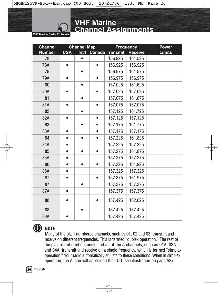
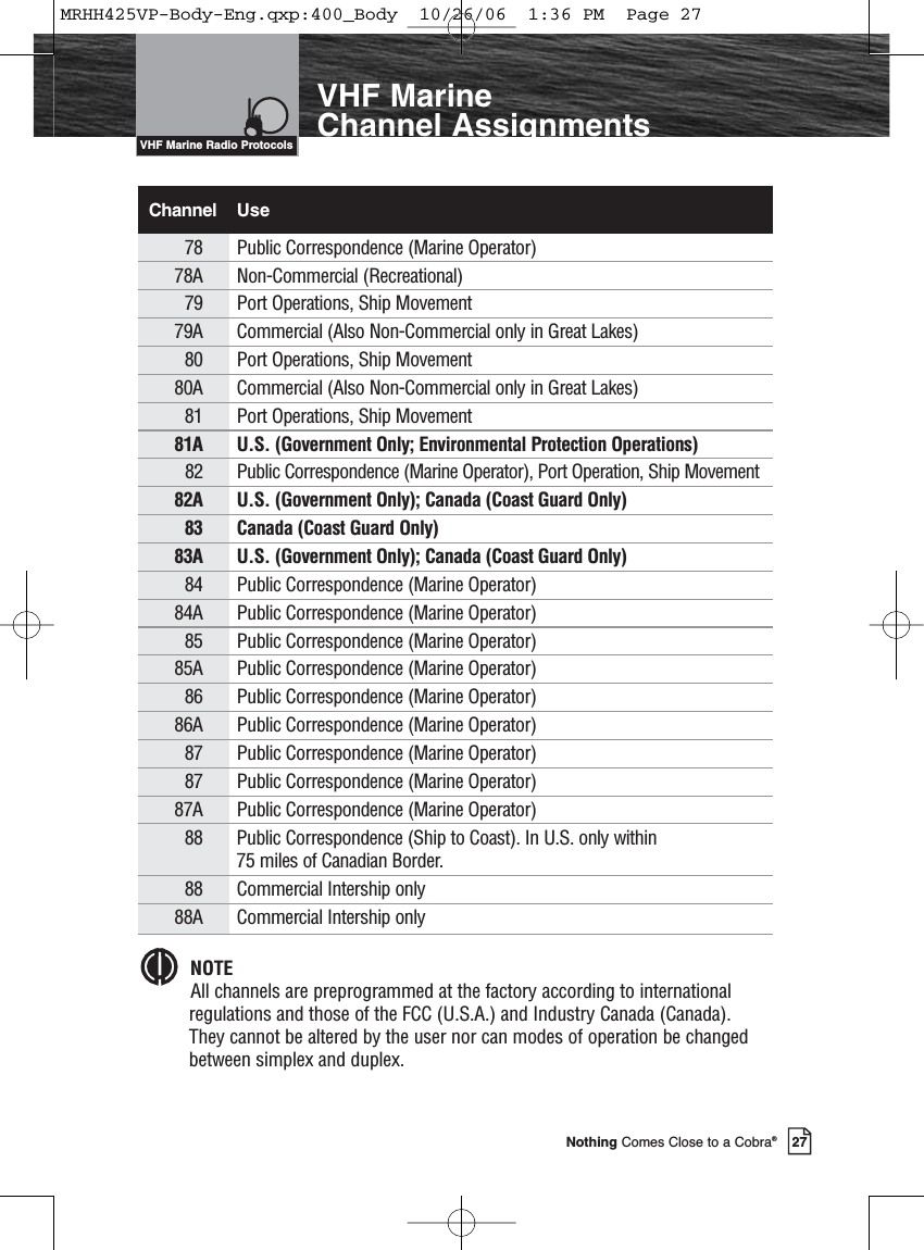
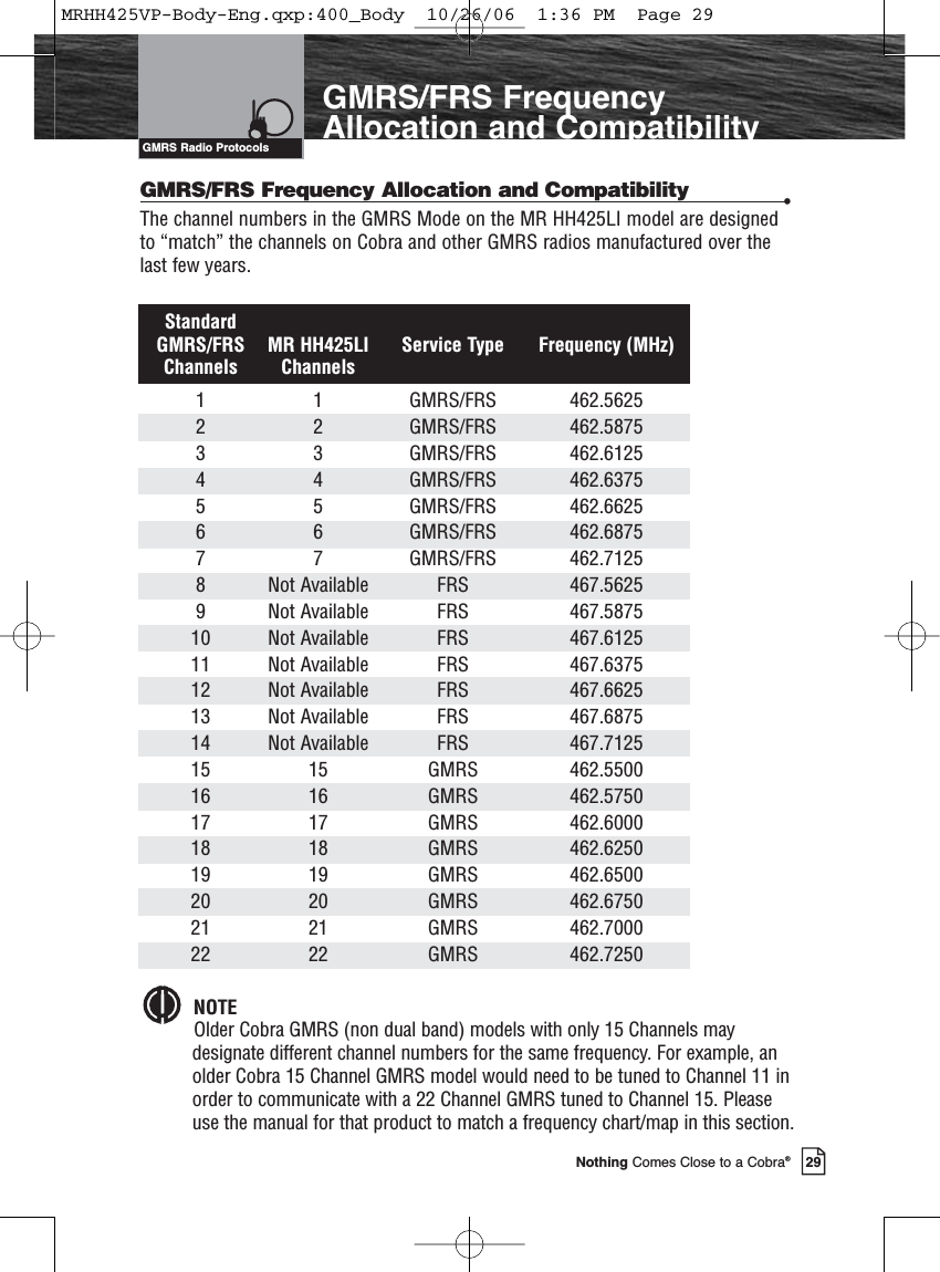
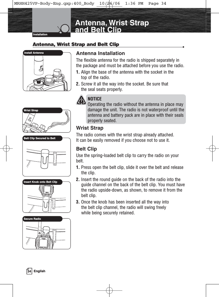
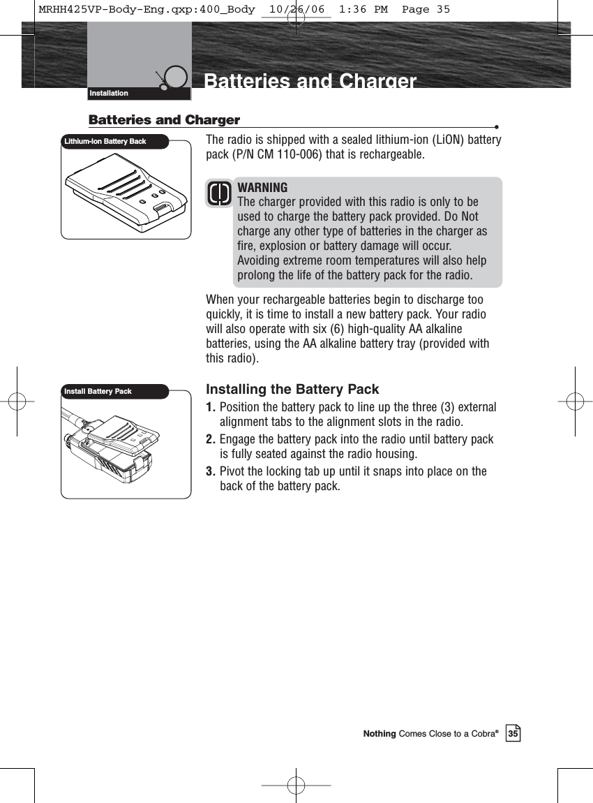
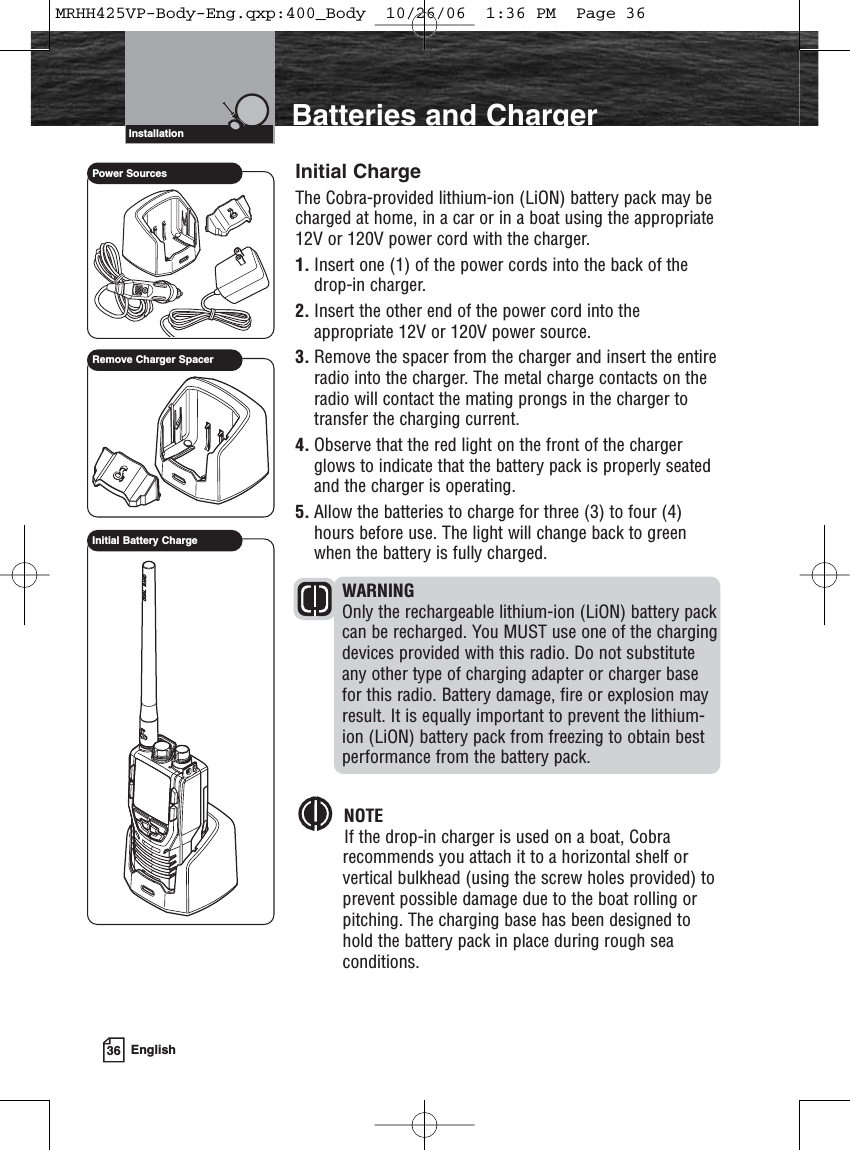
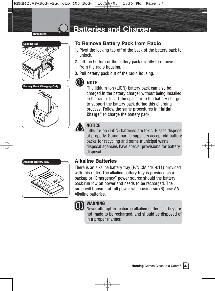
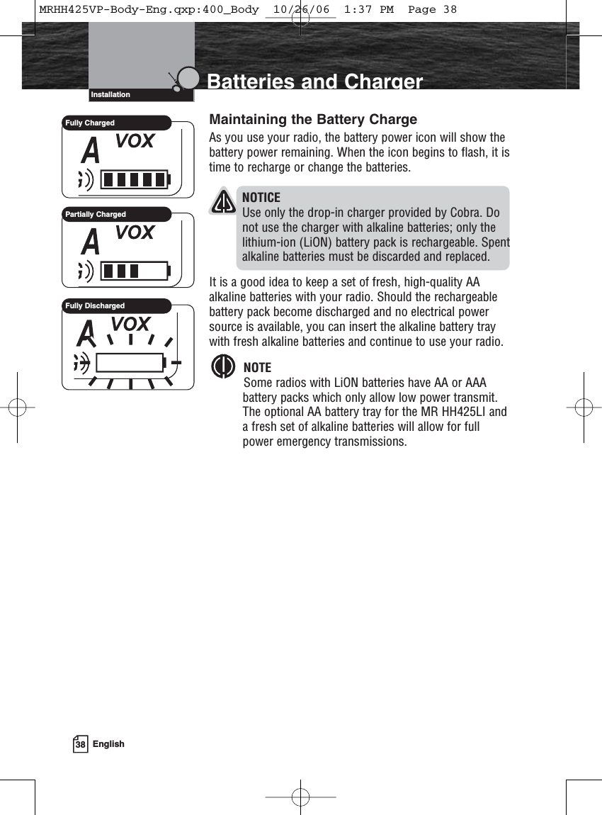
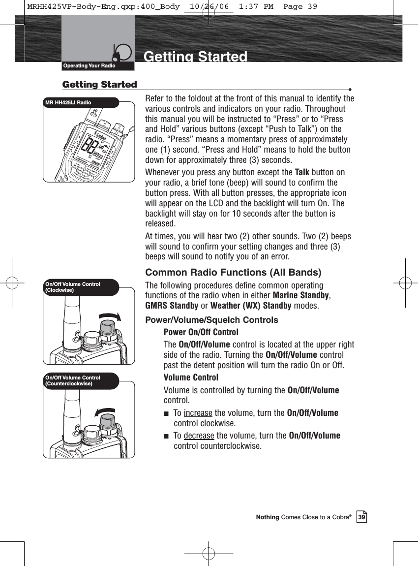
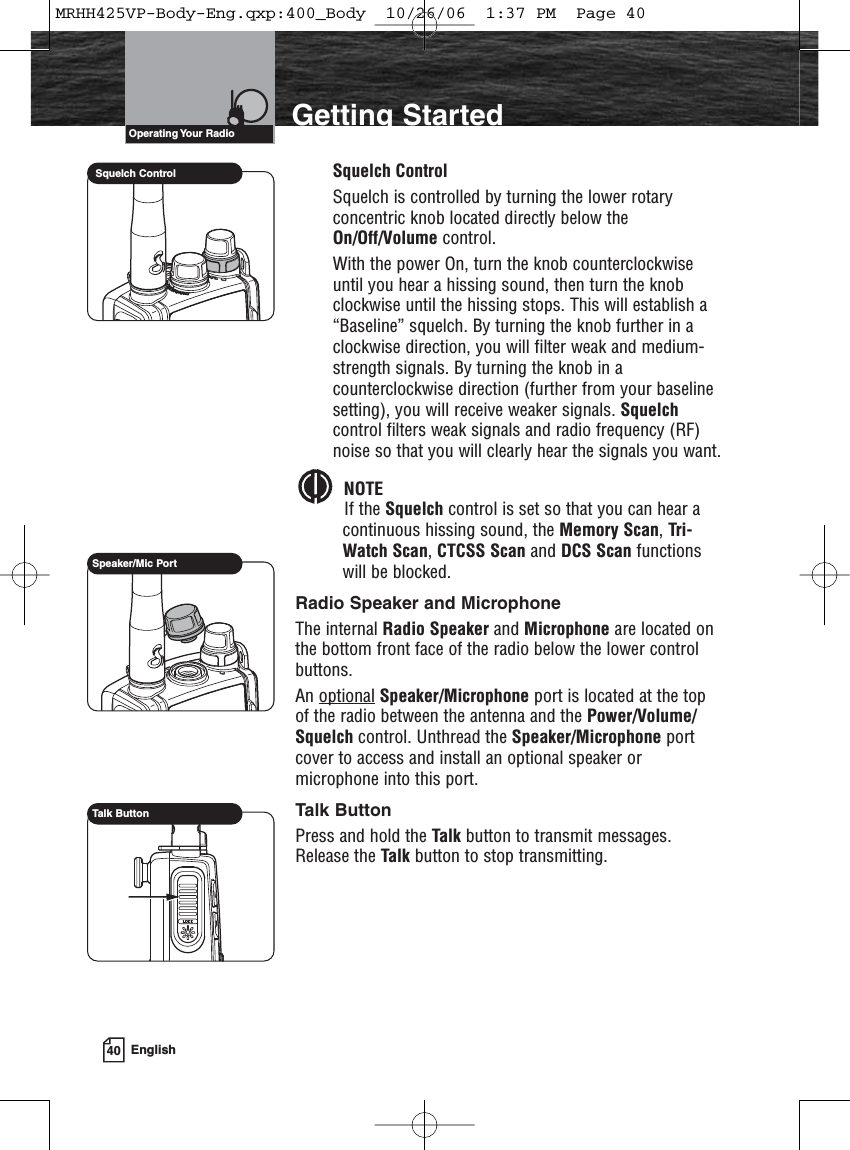
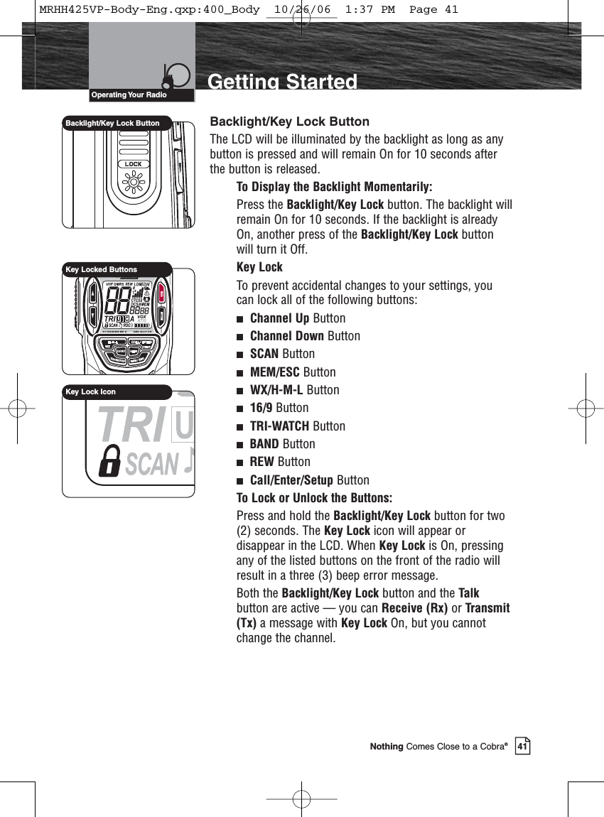
users manual 2
3.
users manual 3
users manual 2
Navigation menu
Upload a User Manual
Namespaces
Wiki Guide
HTML
PDF
Info
Views
User Manual
Discussion / Help
Navigation