Cobra Electronics MRHH425 Handheld Marine Transceiver with GMRS User Manual
Cobra Electronics Corporation Handheld Marine Transceiver with GMRS
Contents
- 1. users manual 1
- 2. users manual 2
- 3. users manual 3
users manual 2
22 English
Introduction
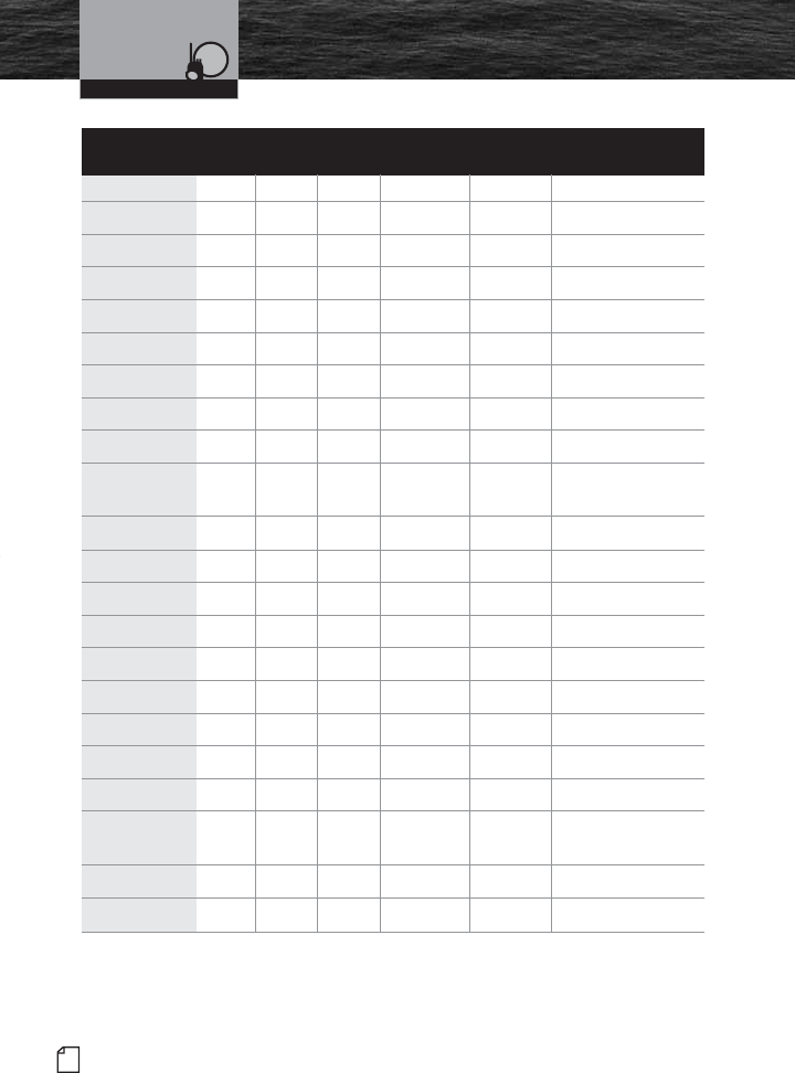
VHF Marine
Channel Assignments
VHF Marine Radio Protocols
Channel Channel Map Frequency Power
Number USA Int’l Canada Transmit Receive Limits
18 •156.900 161.500
18A ••
156.900 156.900
19 •156.950 161.550
19A ••
156.950 156.950
20 •••
157.000 161.600 1 watt CAN
20A •157.000 157.000
21 ••
157.050 161.650
21A ••
157.050 157.050
22 •157.100 161.700
22A ••
157.100 157.100
23 ••
157.150 161.750
23A •157.150 157.150
24 •••
157.200 161.800
25 •••
157.250 161.850
26 •••
157.300 161.900
27 •••
157.350 161.950
28 •••
157.400 162.000
60 ••
156.025 160.625
61 •156.075 160.675
61A ••
156.075 156.075
62 •156.125 160.725
62A • 156.125 156.125
MRHH425VP-Body-Eng.qxp:400_Body 10/26/06 1:36 PM Page 22

Introduction
23
Nothing Comes Close to a Cobra®
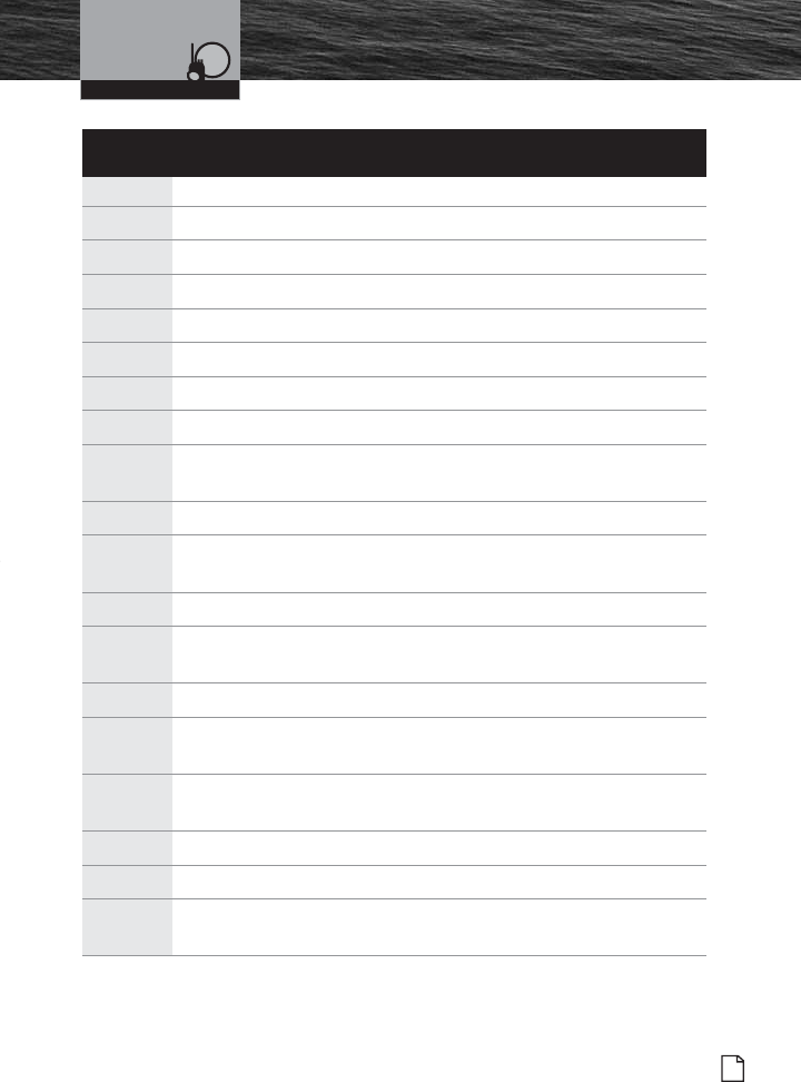
VHF Marine
Channel Assignments
VHF Marine Radio Protocols
Channel Use
18 Port Operations, Ship Movement
18A Commercial
19 Port Operations, Ship Movement
19A Commercial
20 Canada (Coast Guard Only); International (Port Operations, Ship Movement)
20A Port Operations
21 Port Operations, Ship Movement
21A U.S. (Government Only); Canada (Coast Guard Only)
22 Port Operations, Ship Movement
22A U.S. and Canadian Coast Guard Liaison and Maritime Safety Information
Broadcasts that are announced on Channel 16
23 Public Correspondence (Marine Operator)
23A Government Only
24 Public Correspondence (Marine Operator)
25 Public Correspondence (Marine Operator)
26 Public Correspondence (Marine Operator)
27 Public Correspondence (Marine Operator)
28 Public Correspondence (Marine Operator)
60 Public Correspondence (Marine Operator)
61 Public Correspondence (Marine Operator), Port Operation, Ship Movement
61A U.S. (Government Only); Canada (Coast Guard Only);
West Coast (Coast Guard Only); East Coast (Commercial Fishing)
62 Public Correspondence (Marine Operator), Port Operations, Ship Movement
62A West Coast (Coast Guard Only); East Coast (Commercial Fishing)
MRHH425VP-Body-Eng.qxp:400_Body 10/26/06 1:36 PM Page 23

24 English
Introduction
VHF Marine
Channel Assignments
VHF Marine Radio Protocols
Channel Channel Map Frequency Power
Number USA Int’l Canada Transmit Receive Limits
63 •156.175 160.775
63A •156.175 156.175
64 ••
156.225 160.825
64A ••
156.225 156.225
65 •156.275 160.875
65A ••
156.275 156.275
66 •156.325 160.925
66A ••
156.325 156.325 1 watt CAN
67 •••
156.375 156.375 1 watt USA
68 •••
156.425 156.425
69 •••
156.475 156.475
70 •••
RX only 156.525
71 •••
156.575 156.575
72 •••
156.625 156.625
73 •••
156.675 156.675
74 •••
156.725 156.725
75 •156.775 156.775 1 watt Only Int.
76 •156.825 156.825 1 watt Only Int.
77 •••
156.875 156.875 1 watt USA and CAN
MRHH425VP-Body-Eng.qxp:400_Body 10/26/06 1:36 PM Page 24
Introduction
25
Nothing Comes Close to a Cobra®
VHF Marine
Channel Assignments
VHF Marine Radio Protocols
Channel Use
63 Public Correspondence (Marine Operator), Port Operations, Ship Movement
63A Port Operations and Commercial, VTS in selected areas
64 Public Correspondence (Marine Operator), Port Operations, Ship Movement
64A U.S. (Government Only); Canada (Commercial Fishing)
65 Public Correspondence (Marine Operator), Port Operations, Ship Movement
65A Port Operations
66 Public Correspondence (Marine Operator), Port Operations, Ship Movement
66A Port Operations
67 U.S. (Commercial). Used for bridge-to-bridge communications in lower
Mississippi River (Intership Only); Canada (Commercial Fishing), S&R
68 Non-Commercial (Recreational)
69 U.S. (Non-Commercial, Recreational); Canada (Commercial Fishing Only);
International (Intership, Port Operations, Ship Movement)
70 Digital Selective Calling (Voice communications not allowed)
71 U.S. and Canada (Non-Commercial, Recreational);
International (Port Operations, Ship Movement)
72 Non-Commercial (Intership Only)
73 U.S. (Port Operations); Canada (Commercial Fishing Only);
International (Intership, Port Operations, Ship Movement)
74 U.S. (Port Operations); Canada (Commercial Fishing Only);
International (Intership, Port Operations, Ship Movement)
75 Port Operations (Intership Only)
76 Port Operations (Intership Only)
77 Port Operations (Intership only). Restricted to communications
with pilots for movement and docking of ships.
MRHH425VP-Body-Eng.qxp:400_Body 10/26/06 1:36 PM Page 25
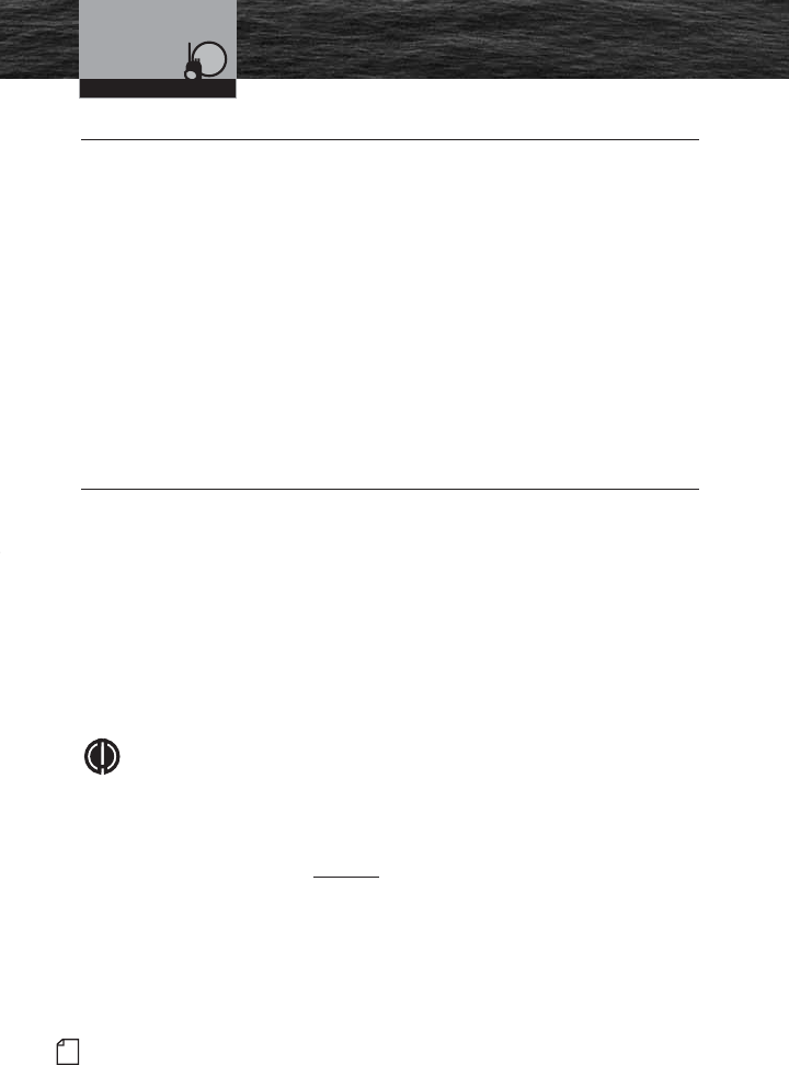
26 English
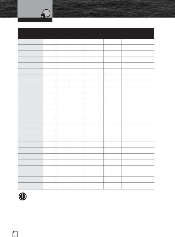
Introduction
Channel Channel Map Frequency Power
Number USA Int’l Canada Transmit Receive Limits
78 •156.925 161.525
78A ••
156.925 156.925
79 •156.975 161.575
79A ••
156.975 156.975
80 •157.025 161.625
80A ••
157.025 157.025
81 •157.075 161.675
81A ••
157.075 157.075
82 •157.125 161.725
82A ••
157.125 157.125
83 ••
157.175 161.775
83A ••
157.175 157.175
84 •••
157.225 161.825
84A •157.225 157.225
85 •••
157.275 161.875
85A •157.275 157.275
86 •••
157.325 161.925
86A •157.325 157.325
87 ••
157.375 161.975
87 •157.375 157.375
87A •157.375 157.375
88 ••
157.425 162.025
88 •157.425 157.425
88A •157.425 157.425
NOTE
Many of the plain-numbered channels, such as 01, 02 and 03, transmit and
receive on different frequencies. This is termed “duplex operation.” The rest of
the plain-numbered channels and all of the A channels, such as 01A, 03A
and 04A, transmit and receive on a single frequency, which is termed “simplex
operation.” Your radio automatically adjusts to these conditions. When in simplex
operation, the A icon will appear on the LCD (see illustration on page A3).
VHF Marine
Channel Assignments
VHF Marine Radio Protocols
MRHH425VP-Body-Eng.qxp:400_Body 10/26/06 1:36 PM Page 26
Introduction
27
Nothing Comes Close to a Cobra®
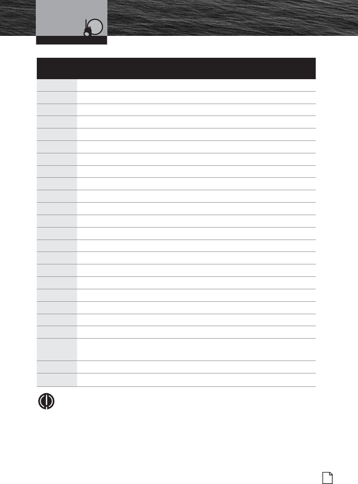
VHF Marine
Channel Assignments
Channel Use
78 Public Correspondence (Marine Operator)
78A Non-Commercial (Recreational)
79 Port Operations, Ship Movement
79A Commercial (Also Non-Commercial only in Great Lakes)
80 Port Operations, Ship Movement
80A Commercial (Also Non-Commercial only in Great Lakes)
81 Port Operations, Ship Movement
81A U.S. (Government Only; Environmental Protection Operations)
82 Public Correspondence (Marine Operator), Port Operation, Ship Movement
82A U.S. (Government Only); Canada (Coast Guard Only)
83 Canada (Coast Guard Only)
83A U.S. (Government Only); Canada (Coast Guard Only)
84 Public Correspondence (Marine Operator)
84A Public Correspondence (Marine Operator)
85 Public Correspondence (Marine Operator)
85A Public Correspondence (Marine Operator)
86 Public Correspondence (Marine Operator)
86A Public Correspondence (Marine Operator)
87 Public Correspondence (Marine Operator)
87 Public Correspondence (Marine Operator)
87A Public Correspondence (Marine Operator)
88 Public Correspondence (Ship to Coast). In U.S. only within
75 miles of Canadian Border.
88 Commercial Intership only
88A Commercial Intership only
NOTE
All channels are preprogrammed at the factory according to international
regulations and those of the FCC (U.S.A.) and Industry Canada (Canada).
They cannot be altered by the user nor can modes of operation be changed
between simplex and duplex.
VHF Marine Radio Protocols
MRHH425VP-Body-Eng.qxp:400_Body 10/26/06 1:36 PM Page 27
28 English
GMRS Communication and
GMRS FCC Licensing
GMRS Communication •
This GMRS (General Mobile Radio Service) feature is a land-mobile service available
for short-distance, two-way communications in the USA. You must have a valid FCC
license to communicate on these channels.
The GMRS/FRS frequencies that radio this radio uses are set aside for
communicating with others while hiking, biking, and working; keeping track of
family and friends at a crowded public event; checking with travel companions in
another car; talking with neighbors; arranging meeting spots with others while
shopping at the mall.
Licensed users will be issued a call sign by the FCC, which should be used for
station identification when operating this radio. GMRS users should also cooperate
by engaging in permissible transmissions only, avoiding channel interference with
other GMRS users, and being prudent with the length of their transmission time.
GMRS FCC Licensing •
This two-way radio operates on GMRS (General Mobile Radio Service) frequencies
which require an FCC (Federal Communications Commission) license. A user must
be licensed prior to transmitting on the GMRS band with this radio. Serious
penalties could result for unlicensed use of GMRS channels, in violation of FCC
rules. Operation of this radio is subject to additional rules specified in 47 C.F.R.
Part 95.
For licensing information and application forms, please call the FCC Hotline at 800-
418-FORM. Request form #159 and form #605. Questions regarding the license
application should be directed to the FCC at 888-CALL-FCC. Additional information is
available on the FCC’s website at www.fcc.gov.
NOTE
Even if you operate this radio on FRS (Family Radio Service) channels at low
power (1 watt), you are required to have an FCC license. Because this radio
operates in the 1 to 5 watt GMRS power range all GMRS rules apply and will
require you have a GMRS license even for FRS (Family Radio Service)
communication. Normal FRS only radios operate at a maximum power of
1/2 watt (500 milliwatt) power and have an integral (non-detachable) antenna.
GMRS Radio Protocols
MRHH425VP-Body-Eng.qxp:400_Body 10/26/06 1:36 PM Page 28
29
Nothing Comes Close to a Cobra®
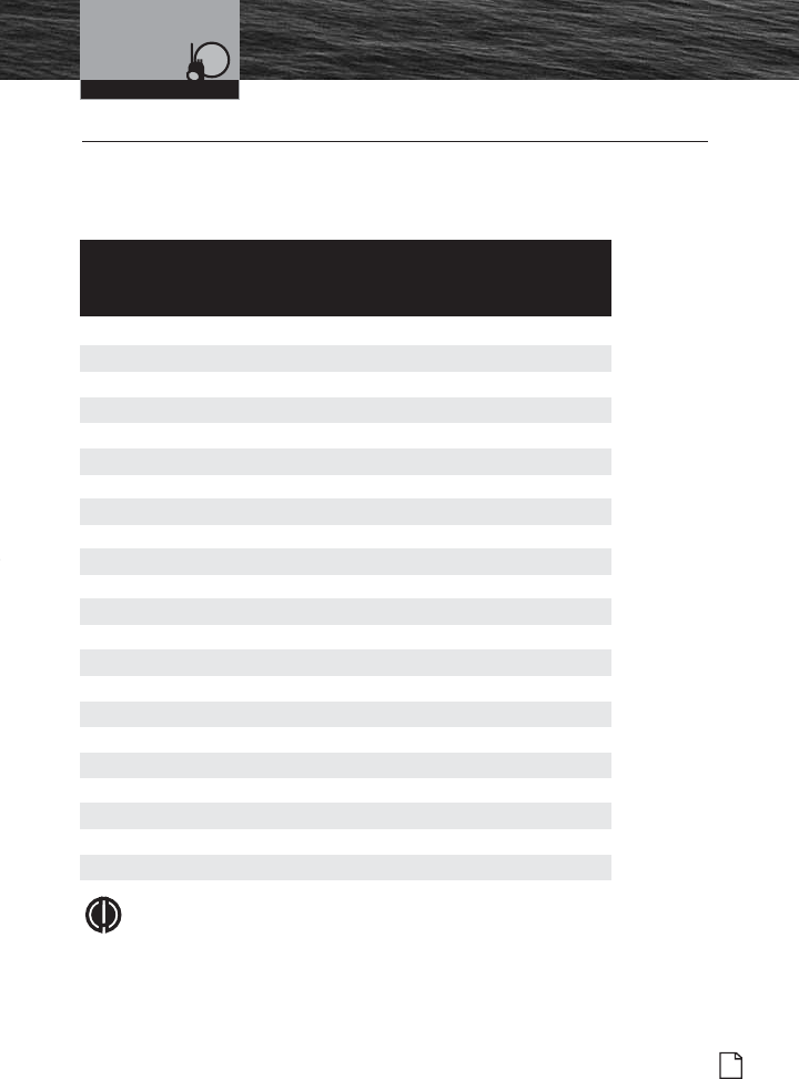
GMRS/FRS Frequency
Allocation and Compatibility
GMRS/FRS Frequency Allocation and Compatibility •
The channel numbers in the GMRS Mode on the MR HH425LI model are designed
to “match” the channels on Cobra and other GMRS radios manufactured over the
last few years.
Standard
GMRS/FRS MR HH425LI Service Type Frequency (MHz)
Channels Channels
1 1 GMRS/FRS 462.5625
2 2 GMRS/FRS 462.5875
3 3 GMRS/FRS 462.6125
4 4 GMRS/FRS 462.6375
5 5 GMRS/FRS 462.6625
6 6 GMRS/FRS 462.6875
7 7 GMRS/FRS 462.7125
8 Not Available FRS 467.5625
9 Not Available FRS 467.5875
10 Not Available FRS 467.6125
11 Not Available FRS 467.6375
12 Not Available FRS 467.6625
13 Not Available FRS 467.6875
14 Not Available FRS 467.7125
15 15 GMRS 462.5500
16 16 GMRS 462.5750
17 17 GMRS 462.6000
18 18 GMRS 462.6250
19 19 GMRS 462.6500
20 20 GMRS 462.6750
21 21 GMRS 462.7000
22 22 GMRS 462.7250
NOTE
Older Cobra GMRS (non dual band) models with only 15 Channels may
designate different channel numbers for the same frequency. For example, an
older Cobra 15 Channel GMRS model would need to be tuned to Channel 11 in
order to communicate with a 22 Channel GMRS tuned to Channel 15. Please
use the manual for that product to match a frequency chart/map in this section.
GMRS Radio Protocols
MRHH425VP-Body-Eng.qxp:400_Body 10/26/06 1:36 PM Page 29
30 English
NOAA Weather Channels and
Alert
NOAA Weather Channels and Alert •
Monitoring the weather will probably be a frequent use of your radio. NOAA provides
continuous, around-the-clock broadcasts of the latest weather information. Taped
weather messages run every four (4) to six (6) minutes and are revised every two
(2) or three (3) hours, or as needed. The Coast Guard also announces weather and
other safety warnings on Channel 16. Smart boaters keep an eye on safety and an
ear to the radio — and never let the weather catch them unaware.
NOAA Emergency Weather Alert
In the event of a major storm or other weather condition requiring vessels at sea or
on other bodies of water to be notified, NOAA broadcasts a 1050 Hz tone that
receivers such as your CobraMarine VHF radio can detect and warn you of a weather
alert condition. When the Weather Alert mode on your radio is On, this signal will
produce a loud tone from the speaker in the radio and will automatically switch to
the alerting weather channel so the alert broadcast can be heard.
NOAA/SAME Weather Alerts
MRHH425VP-Body-Eng.qxp:400_Body 10/26/06 1:36 PM Page 30
31
Nothing Comes Close to a Cobra®
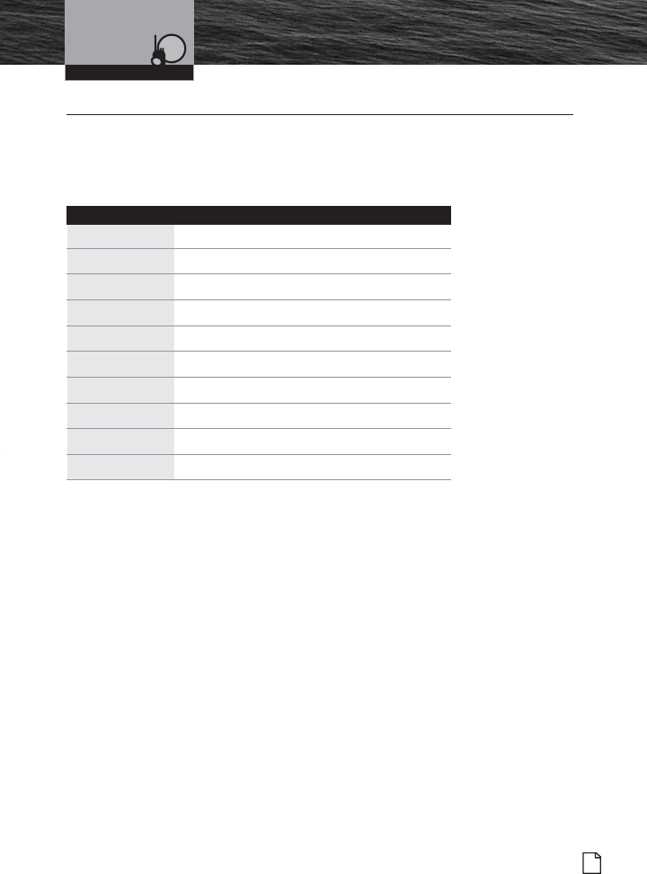
NOAA Test Alert System
NOAA Test Alert System •
To test this system, NOAA broadcasts the 1050 Hz signal every Wednesday sometime
between 11 a.m. and 1 p.m. in each local time zone. Any receiver that can detect the
weather alert tone may use this service to verify that this system is functioning properly.
Weather Frequency/Channel
Channel RX Frequency MHz Weather Channel
1 162.550 NOAA
2 162.400 NOAA
3 162.475 NOAA
4 162.425 NOAA
5 162.450 NOAA
6 162.500 NOAA
7 162.525 NOAA
8 161.650 Canadian
9 161.775 Canadian
10 163.275 NOAA
NOAA/SAME Weather Alerts
MRHH425VP-Body-Eng.qxp:400_Body 10/26/06 1:36 PM Page 31
32 English
Specific Area Message
Encoding (SAME) Alerts
Specific Area Message Encoding (SAME) Alerts •
The MR HH425LI radio is capable of receiving Specific Area Message Encoding
(SAME) Alerts. During an NWR weather SAME alert, a code for your specific
location will alert you to deteriorating weather conditions in a preprogrammed
specific area or a specific event such as a Severe Thunderstorm Watch or Tropical
Storm Warning. There are over 900 National Weather Radio (NWR) service stations
using broadcast frequencies that transmit SAME alerts. You must program your
county, parish or independent city or marine area into the radio.
NOTE
DO NOT program your radio for a louder or clearer station not designated as
a SAME channel. You will not receive the local desired alerts.
The NWR service will then alert you only of weather and other emergencies for all
areas programmed on this radio.
• When an NWR office broadcasts a warning, watch or non-weather emergency,
it also broadcasts a digital SAME code that may be heard as a very brief static
burst, depending on the characteristics of the radio. This SAME code contains
the type of message; county(s) affected, and message expiration time.
• If programmed correctly, this radio will turn to the WX channel so you can
listen to the NWR SAME message. You will hear the 1050 Hz warning alarm
tone as an attention signal, followed by the broadcast message.
• At the end of the broadcast message, you will hear a brief digital end-of-
message static burst followed by a resumption of the NWR broadcast cycle.
NOTE
SAME coverage areas are defined within the “NWR Broadcast Service Area”
and are comprised of named counties, boroughs, metropolitan areas or
portions thereof. NWR “Broadcast Service Area” coverage by State can be
found at http://www.nws.noaa.gov/nwr or by telephone at 1-888-NWRSAME
(1-888-697-7263).
The information at the following website,
http://www.nws.noaa.gov/nwr/indexnw.htm#sametable, will help to program
the SAME alert county codes and respective frequencies into this radio. This
site also lists SAME code Marine zones for bounded and named water areas.
NOAA/SAME Weather Alerts
MRHH425VP-Body-Eng.qxp:400_Body 10/26/06 1:36 PM Page 32
33
Nothing Comes Close to a Cobra®
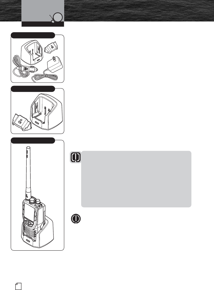
Included in this Package
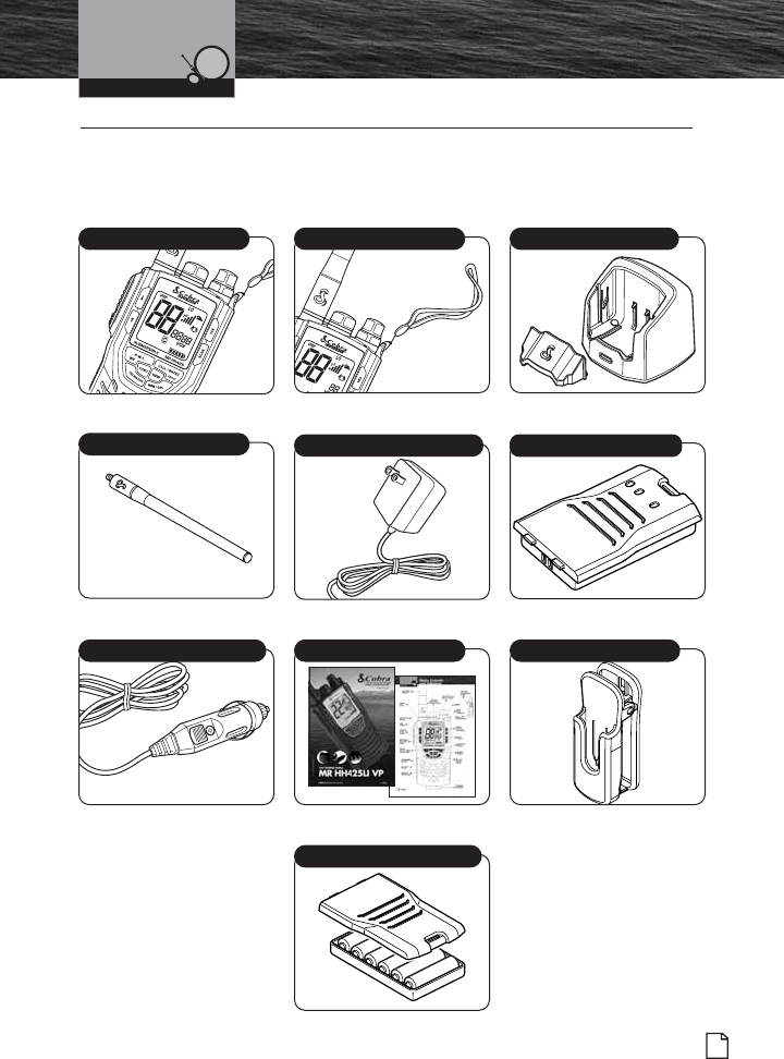
Included in this Package •
You should find all of the following items in the
package with your CobraMarineVHF/GMRS radio:
Installation
Radio Wrist Strap Drop-In Battery Charger
Dual Band Antenna 120V Battery Charger Power Cord Lithium-Ion Battery Pack
12V Battery Charger Power Cord Operating Instruction Manual Spring-Loaded Belt Clip
Alkaline Battery Tray
MRHH425VP-Body-Eng.qxp:400_Body 10/26/06 1:36 PM Page 33
34 English
Antenna, Wrist Strap
and Belt Clip
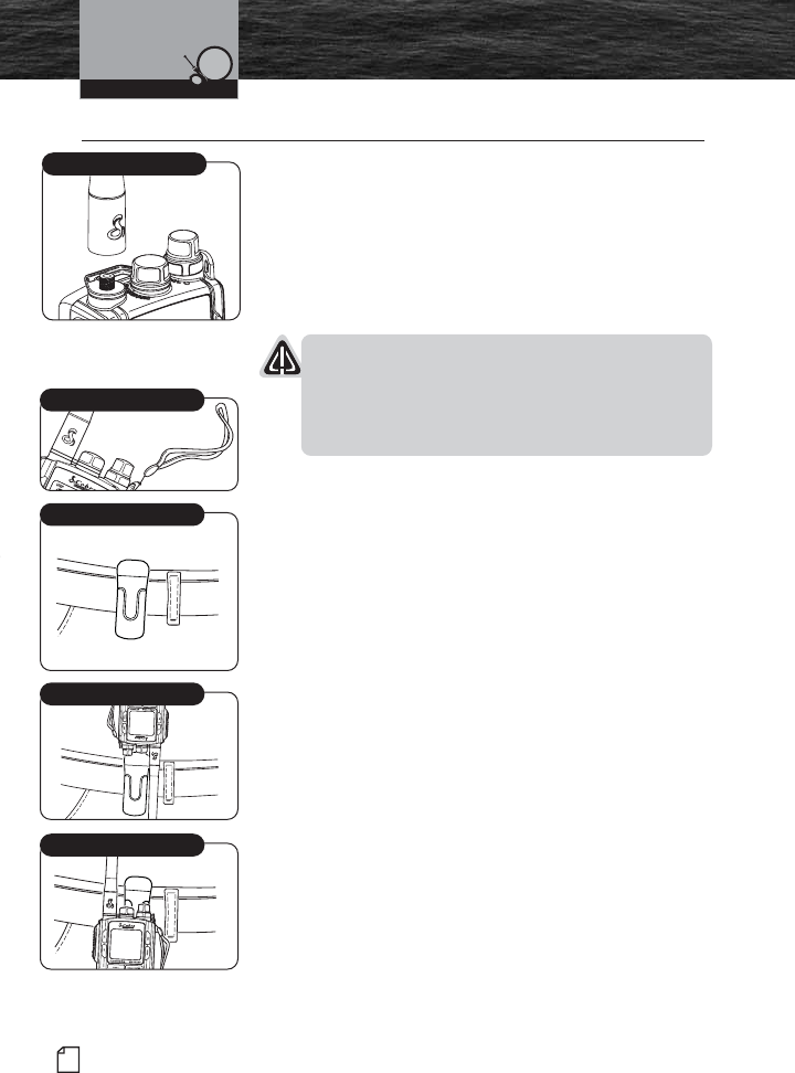
Antenna, Wrist Strap and Belt Clip •
Antenna Installation
The flexible antenna for the radio is shipped separately in
the package and must be attached before you use the radio.
1. Align the base of the antenna with the socket in the
top of the radio.
2. Screw it all the way into the socket. Be sure that
the seal seats properly.
NOTICE
Operating the radio without the antenna in place may
damage the unit. The radio is not waterproof until the
antenna and battery pack are in place with their seals
properly seated.
Wrist Strap
The radio comes with the wrist strap already attached.
It can be easily removed if you choose not to use it.
Belt Clip
Use the spring-loaded belt clip to carry the radio on your
belt.
1. Press open the belt clip, slide it over the belt and release
the clip.
2. Insert the round guide on the back of the radio into the
guide channel on the back of the belt clip. You must have
the radio upside-down, as shown, to remove it from the
belt clip.
3. Once the knob has been inserted all the way into
the belt clip channel, the radio will swing freely
while being securely retained.
VHF Marine Radio ProtocolsInstallation
Install Antenna
Wrist Strap
Belt Clip Secured to Belt
Insert Knob onto Belt Clip
Secure Radio
MRHH425VP-Body-Eng.qxp:400_Body 10/26/06 1:36 PM Page 34
Introduction
35
Nothing Comes Close to a Cobra®
Batteries and Charger
Installation
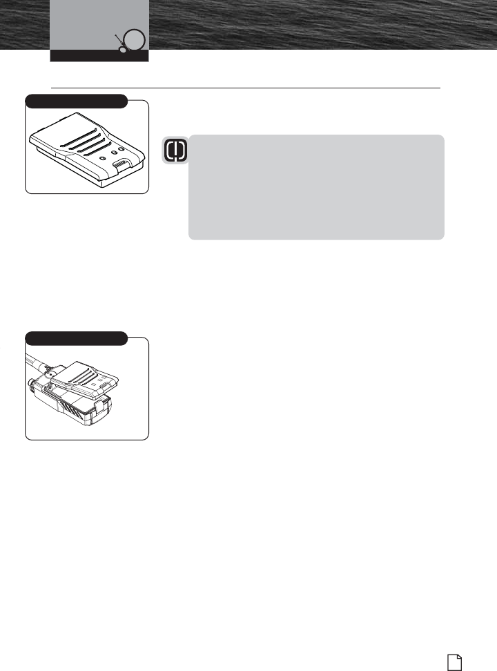
Batteries and Charger •
The radio is shipped with a sealed lithium-ion (LiON) battery
pack (P/N CM 110-006) that is rechargeable.
WARNING
The charger provided with this radio is only to be
used to charge the battery pack provided. Do Not
charge any other type of batteries in the charger as
fire, explosion or battery damage will occur.
Avoiding extreme room temperatures will also help
prolong the life of the battery pack for the radio.
When your rechargeable batteries begin to discharge too
quickly, it is time to install a new battery pack. Your radio
will also operate with six (6) high-quality AA alkaline
batteries, using the AA alkaline battery tray (provided with
this radio).
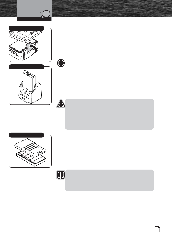
Installing the Battery Pack
1. Position the battery pack to line up the three (3) external
alignment tabs to the alignment slots in the radio.
2. Engage the battery pack into the radio until battery pack
is fully seated against the radio housing.
3. Pivot the locking tab up until it snaps into place on the
back of the battery pack.
Lithium-Ion Battery Back
Install Battery Pack
MRHH425VP-Body-Eng.qxp:400_Body 10/26/06 1:36 PM Page 35
36 English
Introduction Batteries and Charger
Initial Charge
The Cobra-provided lithium-ion (LiON) battery pack may be
charged at home, in a car or in a boat using the appropriate
12V or 120V power cord with the charger.
1. Insert one (1) of the power cords into the back of the
drop-in charger.
2. Insert the other end of the power cord into the
appropriate 12V or 120V power source.
3. Remove the spacer from the charger and insert the entire
radio into the charger. The metal charge contacts on the
radio will contact the mating prongs in the charger to
transfer the charging current.
4. Observe that the red light on the front of the charger
glows to indicate that the battery pack is properly seated
and the charger is operating.
5. Allow the batteries to charge for three (3) to four (4)
hours before use. The light will change back to green
when the battery is fully charged.
WARNING
Only the rechargeable lithium-ion (LiON) battery pack
can be recharged. You MUST use one of the charging
devices provided with this radio. Do not substitute
any other type of charging adapter or charger base
for this radio. Battery damage, fire or explosion may
result. It is equally important to prevent the lithium-
ion (LiON) battery pack from freezing to obtain best
performance from the battery pack.
NOTE
If the drop-in charger is used on a boat, Cobra
recommends you attach it to a horizontal shelf or
vertical bulkhead (using the screw holes provided) to
prevent possible damage due to the boat rolling or
pitching. The charging base has been designed to
hold the battery pack in place during rough sea
conditions.
Installation
Initial Battery Charge
Power Sources
Remove Charger Spacer
MRHH425VP-Body-Eng.qxp:400_Body 10/26/06 1:36 PM Page 36
Introduction
37
Nothing Comes Close to a Cobra®
Batteries and Charger
Installation
To Remove Battery Pack from Radio
1. Pivot the locking tab off of the back of the battery pack to
unlock.
2. Lift the bottom of the battery pack slightly to remove it
from the radio housing.
3. Pull battery pack out of the radio housing.
NOTE
The lithium-ion (LiON) battery pack can also be
charged in the battery charger without being installed
in the radio. Insert the spacer into the battery charger
to support the battery pack during this charging
process. Follow the same procedures in “Initial
Charge” to charge the battery pack.
NOTICE
Lithium-ion (LiON) batteries are toxic. Please dispose
of properly. Some marine suppliers accept old battery
packs for recycling and some municipal waste
disposal agencies have special provisions for battery
disposal.
Alkaline Batteries
There is an alkaline battery tray (P/N CM 110-011) provided
with this radio. The alkaline battery tray is provided as a
backup or “Emergency” power source should the battery
pack run low on power and needs to be recharged. The
radio will transmit at full power when using six (6) new AA
Alkaline batteries.
WARNING
Never attempt to recharge alkaline batteries. They are
not made to be recharged, and should be disposed of
in a proper manner.
Alkaline Battery Tray
Locking Tab
Battery Pack Charging Only
MRHH425VP-Body-Eng.qxp:400_Body 10/26/06 1:36 PM Page 37
38 English
Introduction Batteries and Charger
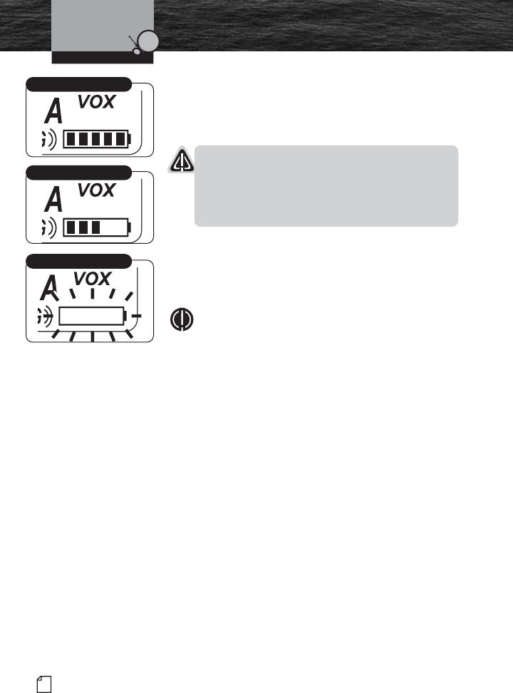
Maintaining the Battery Charge
As you use your radio, the battery power icon will show the
battery power remaining. When the icon begins to flash, it is
time to recharge or change the batteries.
NOTICE
Use only the drop-in charger provided by Cobra. Do
not use the charger with alkaline batteries; only the
lithium-ion (LiON) battery pack is rechargeable. Spent
alkaline batteries must be discarded and replaced.
It is a good idea to keep a set of fresh, high-quality AA
alkaline batteries with your radio. Should the rechargeable
battery pack become discharged and no electrical power
source is available, you can insert the alkaline battery tray
with fresh alkaline batteries and continue to use your radio.
NOTE
Some radios with LiON batteries have AA or AAA
battery packs which only allow low power transmit.
The optional AA battery tray for the MR HH425LI and
a fresh set of alkaline batteries will allow for full
power emergency transmissions.
Installation
Fully Charged
Partially Charged
Fully Discharged
MRHH425VP-Body-Eng.qxp:400_Body 10/26/06 1:37 PM Page 38
39
Nothing Comes Close to a Cobra®
Getting Started •
Refer to the foldout at the front of this manual to identify the
various controls and indicators on your radio. Throughout
this manual you will be instructed to “Press” or to “Press
and Hold” various buttons (except “Push to Talk”) on the
radio. “Press” means a momentary press of approximately
one (1) second. “Press and Hold” means to hold the button
down for approximately three (3) seconds.
Whenever you press any button except the Talk button on
your radio, a brief tone (beep) will sound to confirm the
button press. With all button presses, the appropriate icon
will appear on the LCD and the backlight will turn On. The
backlight will stay on for 10 seconds after the button is
released.
At times, you will hear two (2) other sounds. Two (2) beeps
will sound to confirm your setting changes and three (3)
beeps will sound to notify you of an error.
Common Radio Functions (All Bands)
The following procedures define common operating
functions of the radio when in either Marine Standby,
GMRS Standby or Weather (WX) Standby modes.
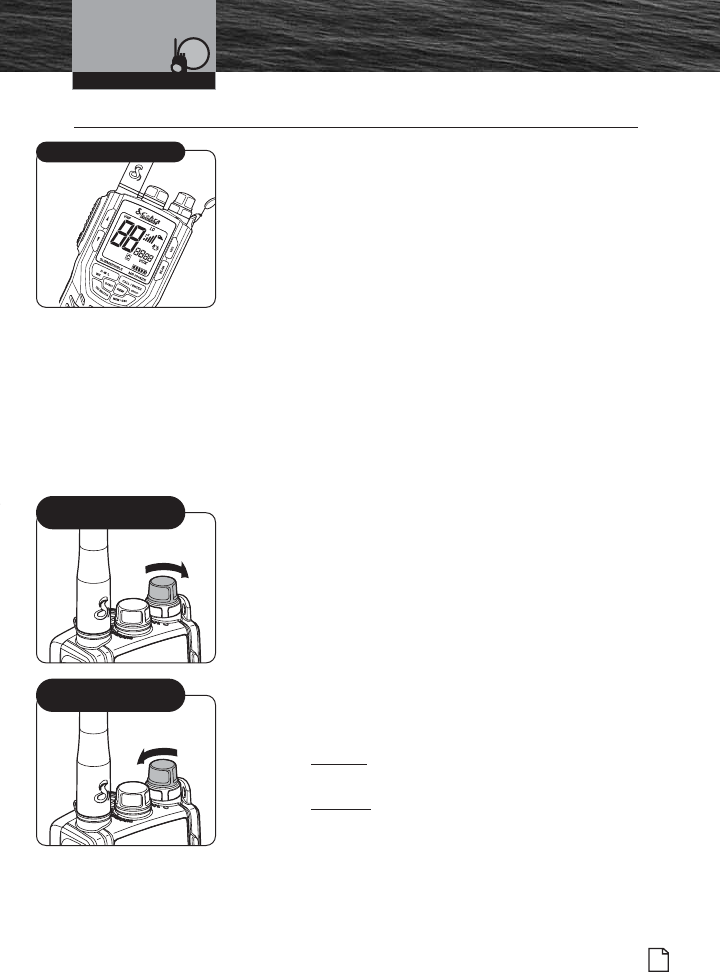
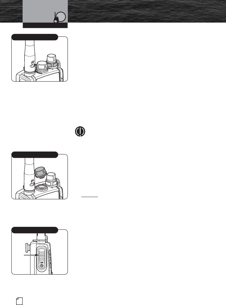
Power/Volume/Squelch Controls
Power On/Off Control
The On/Off/Volume control is located at the upper right
side of the radio. Turning the On/Off/Volume control
past the detent position will turn the radio On or Off.
Volume Control
Volume is controlled by turning the On/Off/Volume
control.
To increase the volume, turn the On/Off/Volume
control clockwise.
To decrease the volume, turn the On/Off/Volume
control counterclockwise.
Getting Started
MR HH425LI Radio
Operating Your Radio
On/Off Volume Control
(Clockwise)
On/Off Volume Control
(Counterclockwise)
MRHH425VP-Body-Eng.qxp:400_Body 10/26/06 1:37 PM Page 39
40 English
Introduction Getting Started
Squelch Control
Squelch is controlled by turning the lower rotary
concentric knob located directly below the
On/Off/Volume control.
With the power On, turn the knob counterclockwise
until you hear a hissing sound, then turn the knob
clockwise until the hissing stops. This will establish a
“Baseline” squelch. By turning the knob further in a
clockwise direction, you will filter weak and medium-
strength signals. By turning the knob in a
counterclockwise direction (further from your baseline
setting), you will receive weaker signals. Squelch
control filters weak signals and radio frequency (RF)
noise so that you will clearly hear the signals you want.
NOTE
If the Squelch control is set so that you can hear a
continuous hissing sound, the Memory Scan, Tri-
Watch Scan, CTCSS Scan and DCS Scan functions
will be blocked.
Radio Speaker and Microphone
The internal Radio Speaker and Microphone are located on
the bottom front face of the radio below the lower control
buttons.
An optional Speaker/Microphone port is located at the top
of the radio between the antenna and the Power/Volume/
Squelch control. Unthread the Speaker/Microphone port
cover to access and install an optional speaker or
microphone into this port.
Talk Button
Press and hold the Talk button to transmit messages.
Release the Talk button to stop transmitting.
Operating Your Radio
Squelch Control
Speaker/Mic Port
Talk Button
MRHH425VP-Body-Eng.qxp:400_Body 10/26/06 1:37 PM Page 40
Introduction
41
Nothing Comes Close to a Cobra®
Getting Started
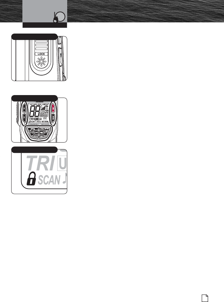
Backlight/Key Lock Button
The LCD will be illuminated by the backlight as long as any
button is pressed and will remain On for 10 seconds after
the button is released.
To Display the Backlight Momentarily:
Press the Backlight/Key Lock button. The backlight will
remain On for 10 seconds. If the backlight is already
On, another press of the Backlight/Key Lock button
will turn it Off.
Key Lock
To prevent accidental changes to your settings, you
can lock all of the following buttons:
Channel Up Button
Channel Down Button
SCAN Button
MEM/ESC Button
WX/H-M-L Button
16/9 Button
TRI-WATCH Button
BAND Button
REW Button
Call/Enter/Setup Button
To Lock or Unlock the Buttons:
Press and hold the Backlight/Key Lock button for two
(2) seconds. The Key Lock icon will appear or
disappear in the LCD. When Key Lock is On, pressing
any of the listed buttons on the front of the radio will
result in a three (3) beep error message.
Both the Backlight/Key Lock button and the Talk
button are active — you can Receive (Rx) or Transmit
(Tx) a message with Key Lock On, but you cannot
change the channel.
Operating Your Radio
Backlight/Key Lock Button
Key Locked Buttons
Key Lock Icon
MRHH425VP-Body-Eng.qxp:400_Body 10/26/06 1:37 PM Page 41
42 English
Introduction Getting Started
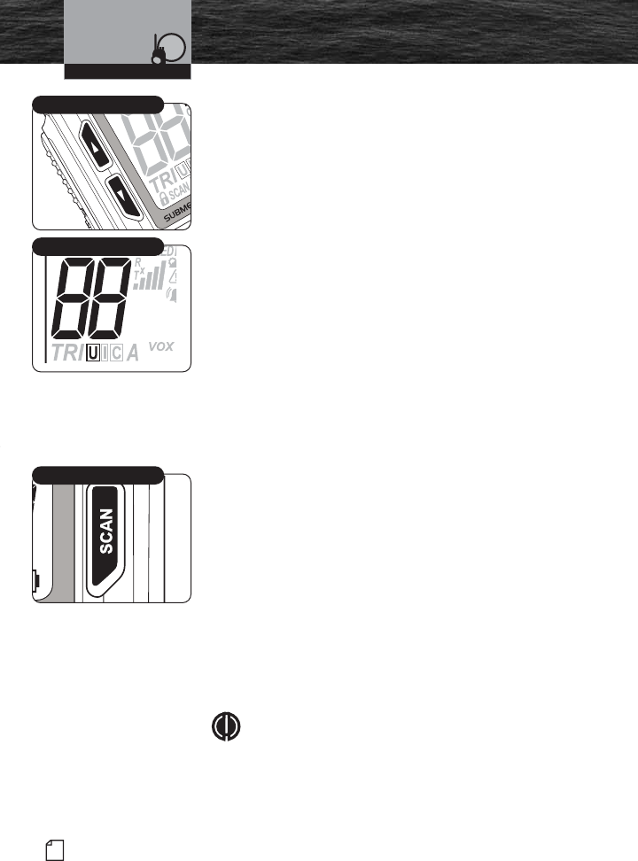
Channel Up/Down Button
Your radio will Receive (Rx) and Transmit (Tx) VHF and
GMRS signals on the channel indicated on the LCD display.
You can change the channel at any time using the Channel
Up/Down button.
To Change Channels:
Press the Channel Up/Down button.
If you are on Channel 88, pressing the Channel Up
button will advance to Channel 01. If you are on
Channel 01, pressing the Channel Down button will
advance to Channel 88.
You can press and hold the Channel Up/Down button
for fast advance. The beep sound will occur only at the
first press of the button and not during fast advance.
If the new channel selected is restricted to low power,
the radio will automatically switch to Low Power mode
and the Low Power icon will appear on the LCD.
If the radio is in the Key Lock mode, the channel will
not change and the three (3) beep error signal will
sound.
SCAN Button
Press and release the SCAN button to scan all channels. The
SCAN icon will display on the LCD display. Scanning begins
at lower channels, and scans to higher channels. Press
Channel Up/Down button to change the scan direction.
When a signal is received in SCAN mode, the radio will
pause 10 seconds before resuming SCAN operation. The
scan will stop when the Talk button is pressed.
In Memory mode, press and release the SCAN button to
scan all memory channels. Because the unit is already in the
Memory Channel mode, only the channels in the memory
bank will be displayed.
NOTE
Memory channels need to be saved to effectively
enter the Memory Channel mode and scan all
memory channels.
Operating Your Radio
SCAN Button
Channel Up/Down Button
Currently On Channel 88
MRHH425VP-Body-Eng.qxp:400_Body 10/26/06 1:37 PM Page 42
Introduction
43
Nothing Comes Close to a Cobra®
Getting Started
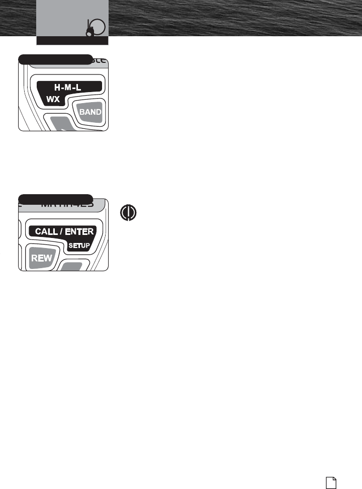
High/Medium/Low (H-M-L) Power Button
Your radio can transmit selectively at 1, 3 or 5 watts of
power. Cobra suggests you maintain the low power setting
for short-range communications. You will conserve battery
life and avoid overpowering nearby stations with a low
power setting signal. Use the high power setting for long-
range communications or when you do not receive a
response to a signal sent at 1 watt.
To Toggle Between H-M-L Power Modes:
Press the H-M-L Power button. The LCD will show
which mode is in effect. Some channels are restricted
for a maximum use of 1 watt. Your radio will
automatically set the power to Low Power mode when
you select those channels.
NOTE
Some channels, frequency bands and countries of
use might not be able to operate in High Power
mode. For example, units sold in Canada will not
transmit using the 5 watt High Power mode.
Call /Enter/Setup Button
The Call/Enter/Setup button has multiple functions. It is
generally used in the following ways:
Press and release to transmit your unique Call Tone
signal to another radio.
Press and hold to enter any Setup menu.
Functions as an ENTER button when making a selection
in any Setup menu.
Operating Your Radio
H-M-L Power Button
Call/Enter/Setup Button
MRHH425VP-Body-Eng.qxp:400_Body 10/26/06 1:37 PM Page 43
44 English
Introduction Setup Mode Programming
Setup Mode Programming •
The following series of procedures is designed to allow you to set the programmable
features of your radio. Correctly following these steps results in a minimal amount
of radio setup programming time.
NOTE
When in any of the Setup modes (Marine (VHF), GMRS or WX Alert), if you
stop programming for longer than 15 seconds, your entry will be saved and
the radio will go back to the specific Standby mode that you were in when you
started programming. When you return to Setup mode and continue
programming you will see the last “value” displayed. While in any Setup mode,
you will not receive any signal reception.
Programming these features will allow you to customize certain features of this
radio to enhance your “On-Water” audio needs.
Start from Marine Standby mode to begin Marine (VHF) Setup programming. Press
and hold the Call/Enter/Setup button for two (2) seconds to enter the programming
mode.
Marine (VHF) Mode Programming
Operating Your Radio
MRHH425VP-Body-Eng.qxp:400_Body 10/26/06 1:37 PM Page 44
Introduction
45
Nothing Comes Close to a Cobra®
Setup Mode Programming
USA/International/Canada Channel Maps
Three (3) sets of VHF Channel Maps have been established
for marine use in the USA, Canada and the rest of the world
(International). Most of the channels are the same for all
three (3) maps, but there are definite differences (see table
on pages 20 through 27). Your radio has all three (3) maps
built into it and will operate correctly in whichever area you
choose.
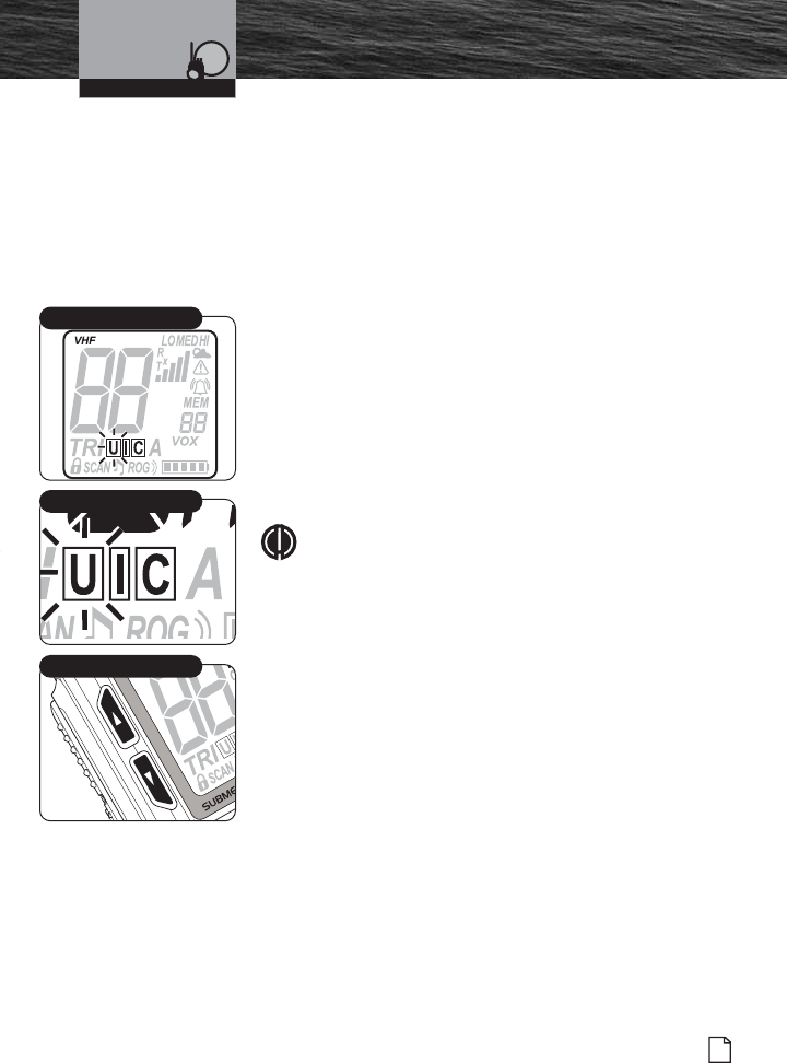
To Set Channel Map Operating Area:
1. The Channel Map mode is the first mode that
begins the Marine (VHF) Setup programming.
2. U, Iand Cicons will display, with the current setting
(the Uicon is the default) flashing.
3. Press Channel Up/Down button to select the U, Ior
Cicon.
4. Press Call/Enter/Setup button to save this entry and
move to the next setup programming mode.
NOTE
One or two of the channel maps might have been
disabled for sales of this radio in some countries.
Operating Your Radio
Set Channel Map
Channel Up/Down Button
Active Channel Map Icon
MRHH425VP-Body-Eng.qxp:400_Body 10/26/06 1:37 PM Page 45
46 English
Introduction Setup Mode Programming
Voice Activated Transmit (VOX) Mode
In VOX mode, your radio can be used “hands-free,”
automatically transmitting when you speak. You can also set
the VOX sensitivity level to fit the volume of your voice and
avoid transmissions triggered by background noise.
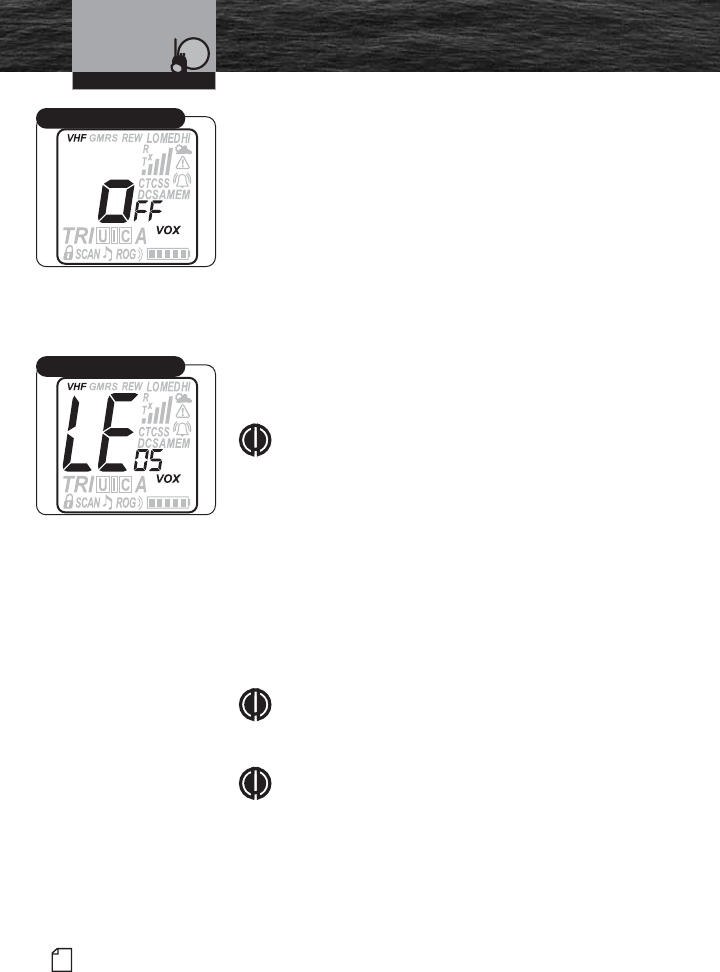
To turn VOX Mode On or Off:
1. Display will show VOX icon and ON or OFF flashing.
2. Press Channel Up/Down button to select ON or
OFF.
3. Press Call/Enter/Setup button to save this entry and
move to the next setup programming mode.
To set VOX Sensitivity Level:
1. The display will show LE (level). VOX icon and 05
will be flashing.
NOTE
VOX sensitivity level is only visible when VOX is On.
2. Press Channel Up/Down button to change volume
level of your choice. Remember, this selection is
your voice sensitivity level during hands-free
operation.
05 - indicates a Low (quiet) voice setting.
03 - indicates a Medium voice setting.
01 - indicates a High (loud) voice setting.
3. Press Call/Enter/Setup button to save this entry and
move to the next setup programming mode.
NOTE
VOX will be turned Off automatically when the radio
is turned Off. This will avoid accidental transmissions.
NOTE
Once set, this is a global setting when in all radio
modes.
Operating Your Radio
VOX Mode
VOX Level
MRHH425VP-Body-Eng.qxp:400_Body 10/26/06 1:37 PM Page 46
Introduction
47
Nothing Comes Close to a Cobra®
Setup Mode Programming
VibrAlert®Mode
In VibrAlert®mode, your radio can alert you to incoming
signals by sounding an audible call tone, a silent vibration or
both.
NOTE
VOX will be turned Off automatically when the radio
is turned Off. This will avoid accidental transmissions.
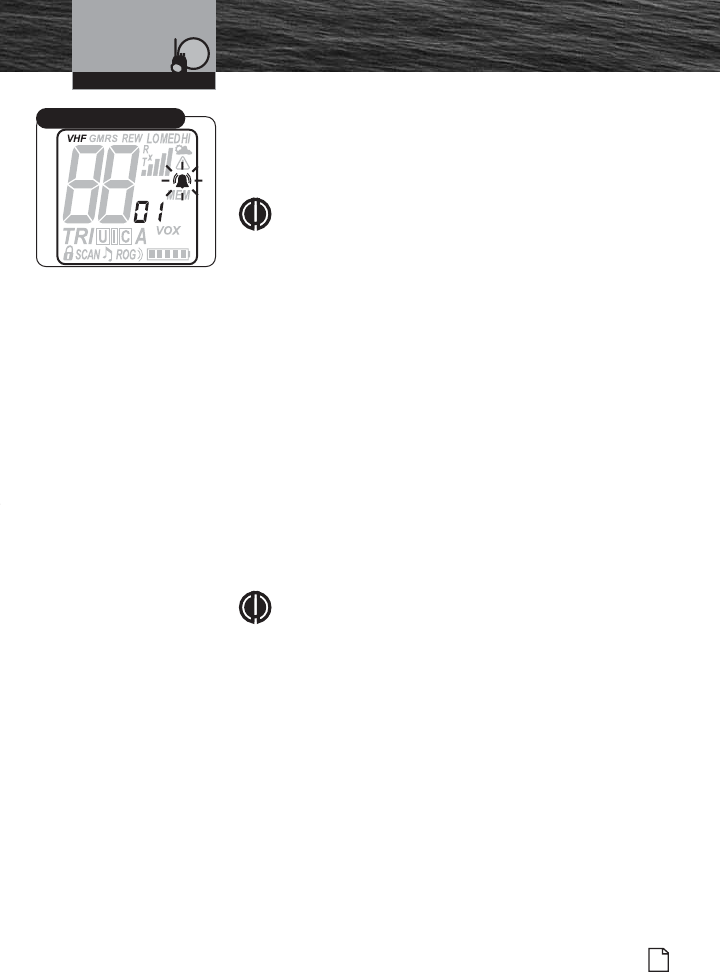
To set VibrAlert®:
1. The display will show either the Vibrate icon (shake
bars), Call Tone icon (bell shape) or a combination
VibrAlert®icon.
2. The present setting of either, 01, 02 or 03 will be
flashing.
3. Press Channel Up/Down button to select one of the
following:
01 = VibrAlert®On (both shake bars and bell
shape).
02 = Vibrate On (shake bars only).
03 = Call Tone Only On (bell shape only).
4. Press Call/Enter/Setup button to save this entry and
move to the next setup programming mode.
NOTE
Once set, this is a global setting when in all radio
modes.
Operating Your Radio
VibrAlert®Tone Alert
MRHH425VP-Body-Eng.qxp:400_Body 10/26/06 1:37 PM Page 47
48 English
Introduction Setup Mode Programming
Call Tone Mode
In Call Tone mode, your radio can alert you to incoming
signals by sounding an audible call tone, a silent vibration or
both. This setting will also allow you to transmit a unique
Call Tone alert to identify your radio when you transmit
messages. You can select from one of 10 different Call Tone
signals.
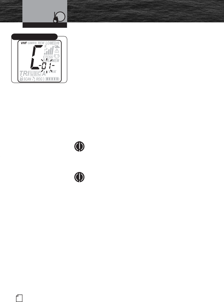
To Set Call Tone:
1. From the previous press of the Call/Enter/Setup
button, the LCD will display the letter “C” and the
current Call Tone number (01 through 10).
2. Press the Channel Up/Down button to select a
different Call Tone. An example of each call tone will
sound for 1.5 seconds.
3. Press Call/Enter/Setup button to save this entry and
move to the next setup programming mode.
NOTE
Call Tones are not usually used for Marine VHF
communications. We allow you to turn it On for your
unique communication needs.
NOTE
Once set, this is a global setting when in all radio
modes.
Operating Your Radio
Call Tone Mode
MRHH425VP-Body-Eng.qxp:400_Body 10/26/06 1:37 PM Page 48
Introduction
49
Nothing Comes Close to a Cobra®
Setup Mode Programming
Roger Beep Mode
In Roger Beep mode, your listener will hear an audible tone
when you release the Talk button. This alerts your listener
that you are finished talking and it is OK for them to speak.
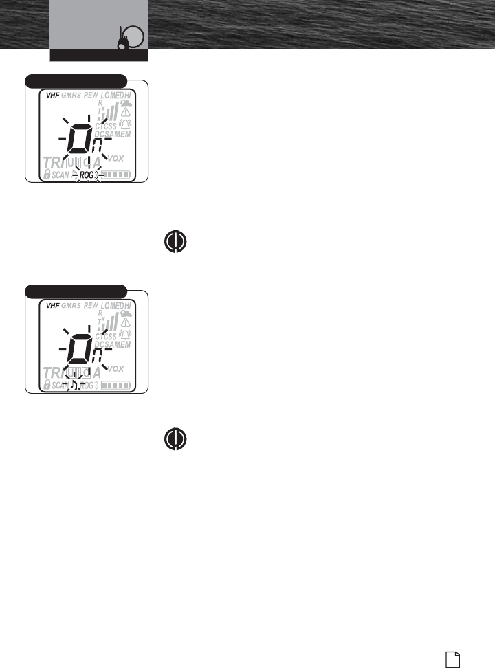
To Set Roger Beep On or Off:
1. Display will show ROG icon and ON or OFF flashing.
2. Press Channel Up/Down button to select ON or
OFF. ROG will be displayed when On.
3. Press Call/Enter/Setup button to save this entry and
move to the next setup programming mode.
NOTE
Once set, this is a global setting when in all radio
modes.
Key Tone Mode
In Key Tone mode, an audible tone will sound each time a
button is pressed or you change a setting.
To Set Key Tone On or Off:
1. Display will show Key Tone icon and ON or OFF
flashing.
2. Press Channel Up/Down button to select ON or
OFF.
3. Press Call/Enter/Setup button to save entry.
NOTE
Once set, this is a global setting when in all radio
modes.
You have now ended Marine (VHF) Setup programming
mode and will enter Marine Standby mode.
Operating Your Radio
Roger Beep Mode
Key Tone Mode
MRHH425VP-Body-Eng.qxp:400_Body 10/26/06 1:37 PM Page 49
50 English
Introduction Setup Mode Programming
The GMRS (General Mobile Radio Service) feature is a land-
mobile service available for short-distance, two-way
communications in the USA. You must have a valid FCC
license to communicate on these channels (see page 28).
Start from GMRS Standby mode to begin GMRS Setup
programming. Press and hold the Call/Enter/Setup button
for two (2) seconds to enter the programming mode.
CTCSS and DCS Coding Mode
Continuous Tone Controlled Squelch System (CTCSS) and
Digital Coded Squelch (DCS) coding are used in two-way
radio systems. These are sub-audible frequencies or digital
tones that are sent continuously with speech to engage
other radios with this feature. This feature is generally used
between talk groups on shared channels. Only radios with
the same subcode set will hear your transmission.
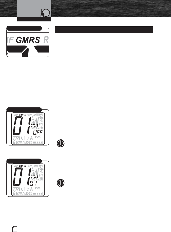
To Set CTCSS Code Entry:
1. The CTCSS code entry mode is the first mode that
begins the GMRS Setup programming.
2. Display will show CTCSS icon and OFF icon
flashing.
NOTE
If CTCSS was previously set to a Code number,
display will show the current GMRS channel and
flash the CTCSS icon and Code number.
3. Codes begin at 01 and go to 38, followed by OFF,
and return back to 01 again. The last used GMRS
channel will be shown in the large digit display.
NOTE
If CTCSS is On, then DCS must be Off. If DCS is On,
then CTCSS must be Off.
4. Press Channel Up/Down button to change code
number, or press and hold Channel Up/Down
button to rapid advance (scroll).
5. Press Call/Enter/Setup button to save entry and
move to the next setup programming mode.
GMRS Mode Programming
Operating Your Radio
GMRS Mode
CTCSS Code Entry
CTCSS Code Number
MRHH425VP-Body-Eng.qxp:400_Body 10/26/06 1:37 PM Page 50