CommScope Technologies RP-A2114 Multi-Band Radio User Manual ORP install
CommScope Technologies LLC Multi-Band Radio ORP install
UserManual.wiki
>
CommScope Technologies
>
RP A2114 User Manual
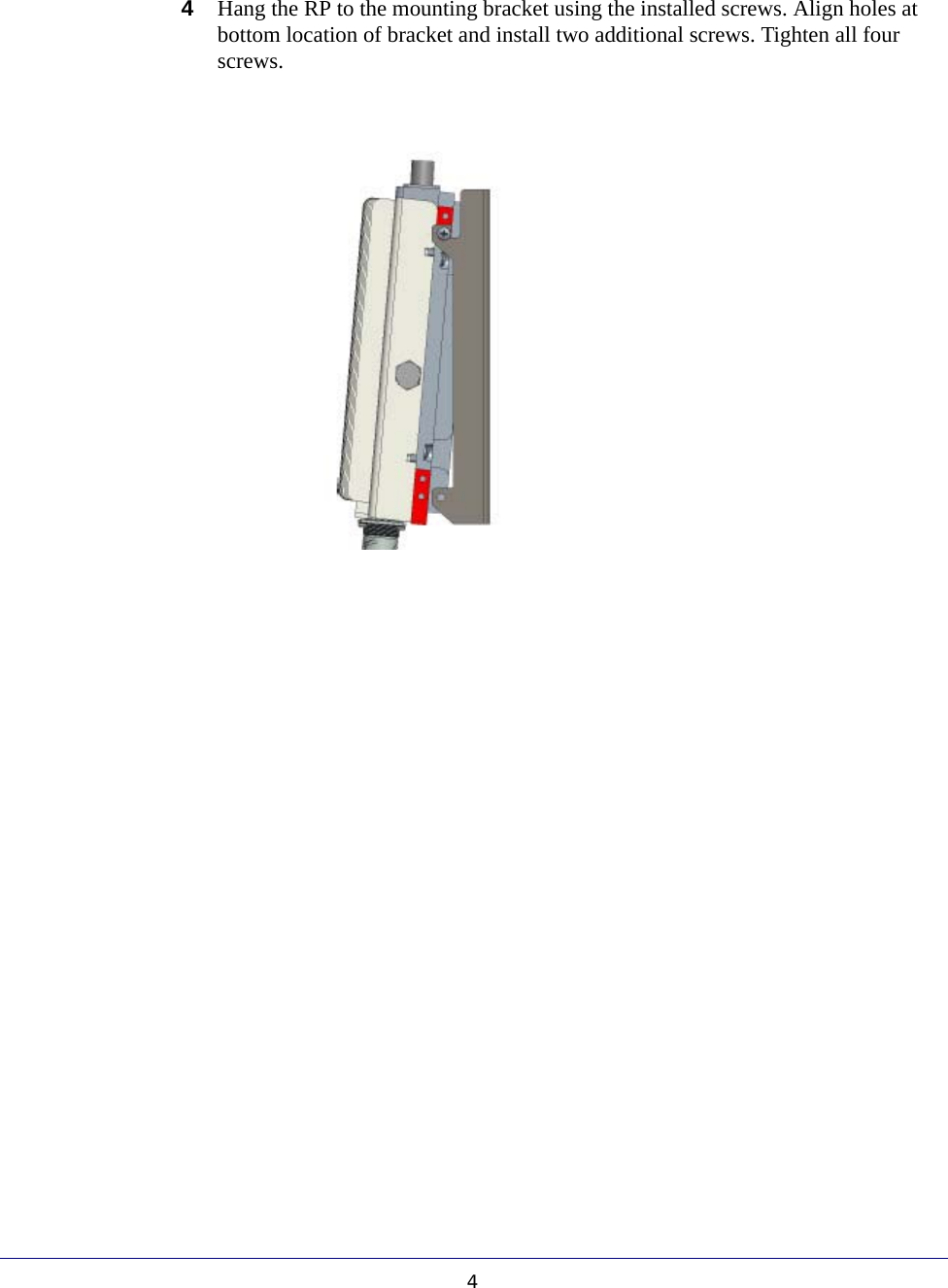
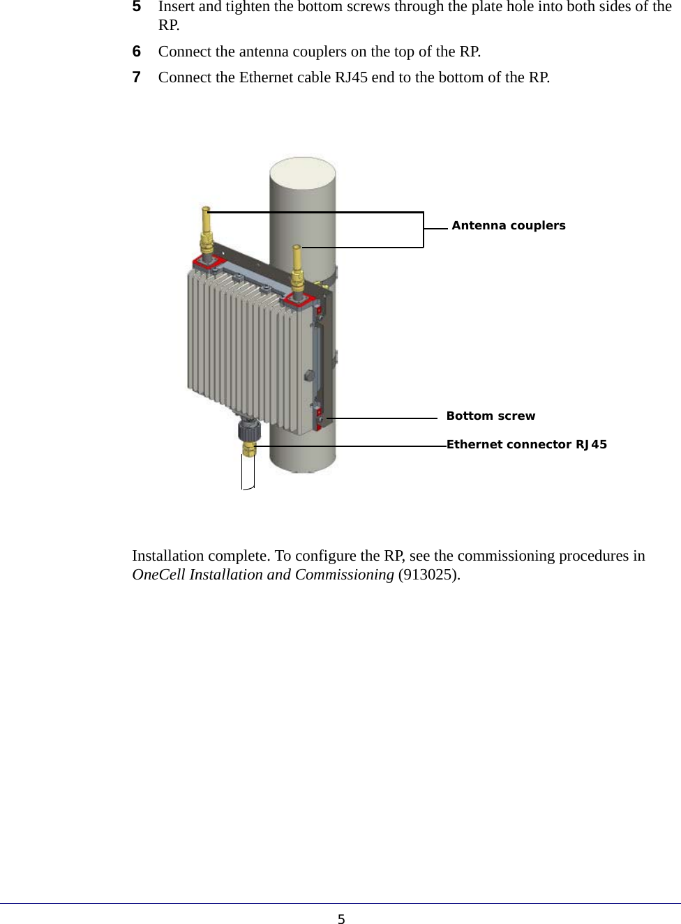
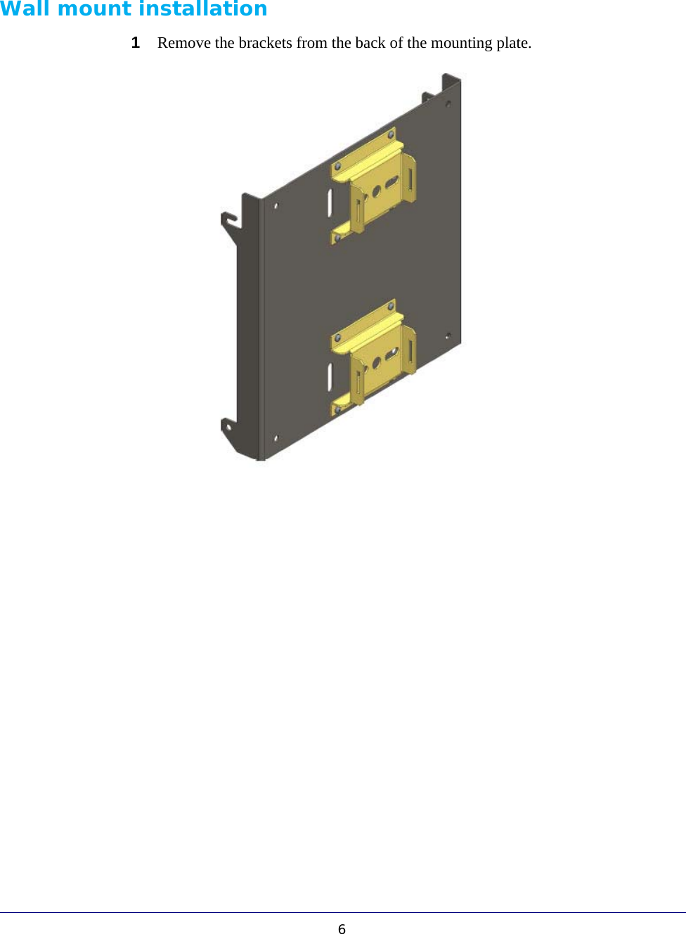
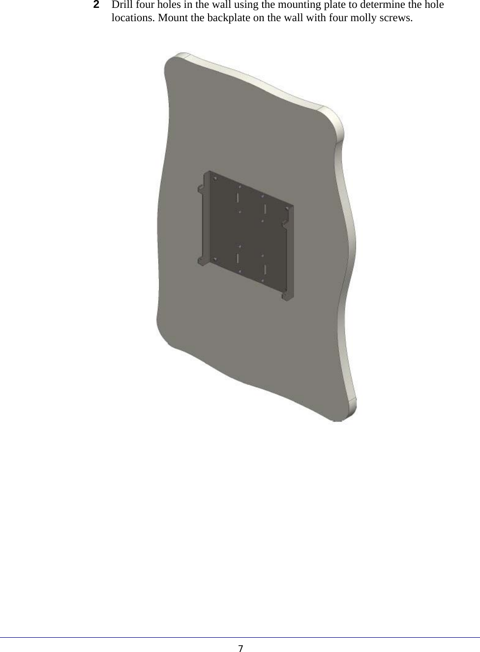
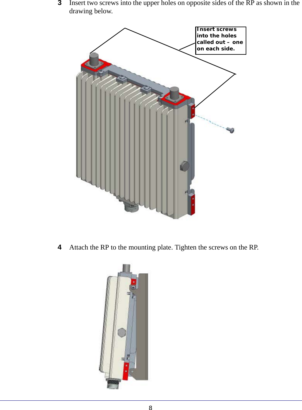
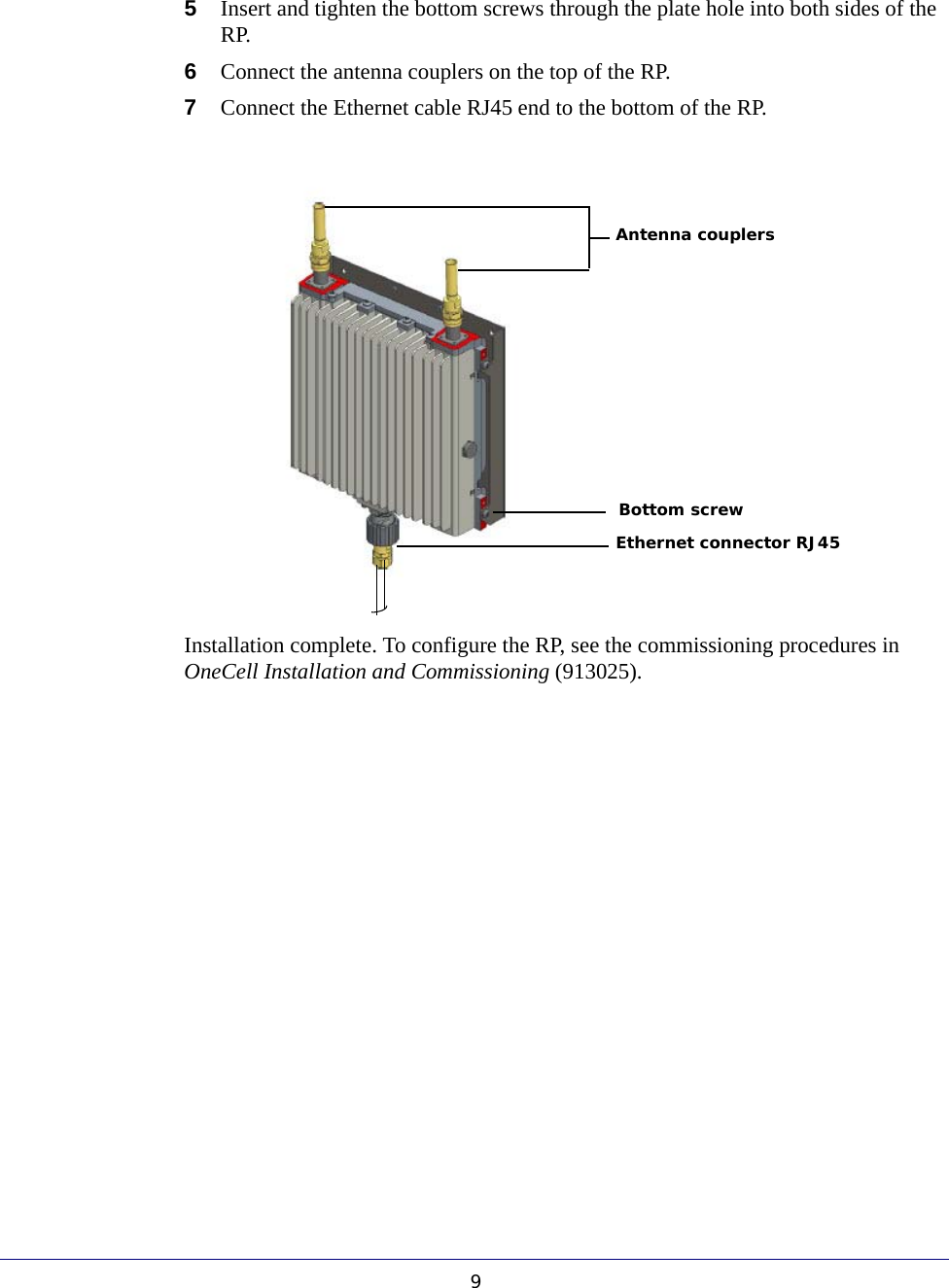
Installation
Navigation menu
Upload a User Manual
Namespaces
Wiki Guide
HTML
PDF
Info
Views
User Manual
Discussion / Help
Navigation