CommScope Technologies RP-A2114 Multi-Band Radio User Manual ORP install
CommScope Technologies LLC Multi-Band Radio ORP install
Installation

Outdoor Radio Point Installation
Document Number: 913032
Document Revision: 1.04
Date: February 2016
OneCell®
1
What’s in the box
The outdoor Radio Point (RP) ships with the following hardware:
• Radio Point with mounting plate and brackets attached
• Four mounting screws (M5 x 10mm)
• RJ45, IP67 connector
• Two N-type antenna couplers
Mounting the Radio Point (RP) on a pole requires the following hardware provided by
the system integrator:
• Two adjustable clamps
Mounting the Radio Point (RP) on a wall requires the following hardware provided by
the system integrator:
• Four molly screws capable – 50 lb (23 kg) minimum rating
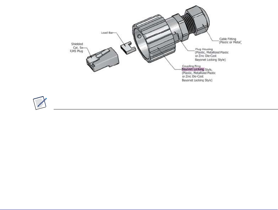
Before installing the RP on the pole, terminate the RP end of the Ethernet cable with
the RJ45, IP67 connector provided in the box.
NOTE
For more information on installing Radio Points, see OneCell Installation and
Commissioning (913025).
2
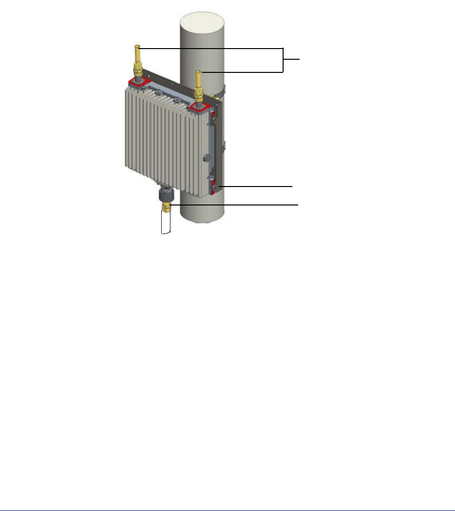
Pole mount installation
NOTE
The minimum pole diameter requirement is 4'' (102mm).
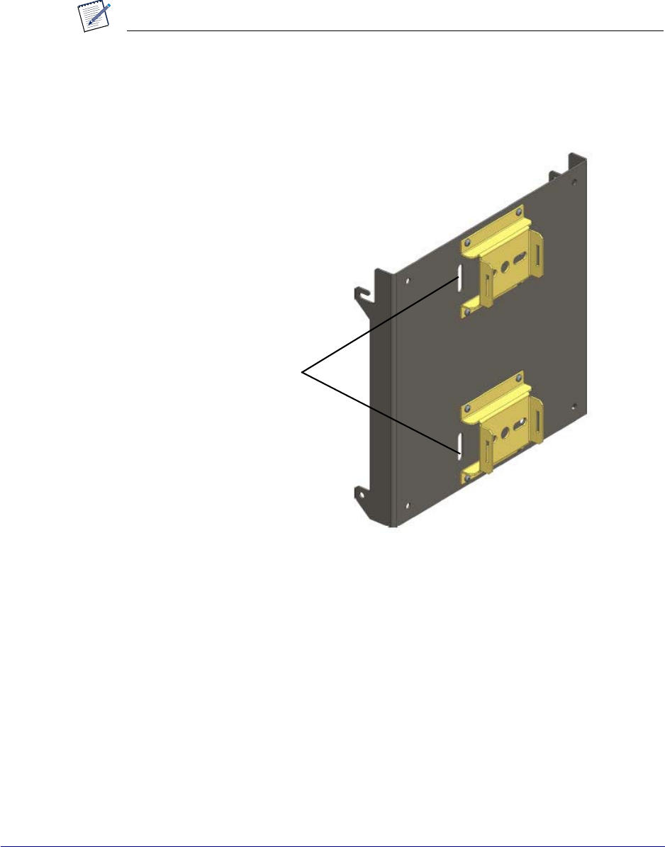
1Slide the adjustable clamp through the slots on each RP mounting bracket on the
RP plate.
Slide adjustable
clamp end
through slots
3
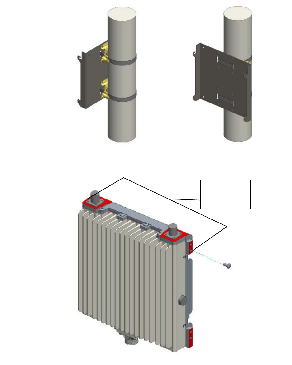
2Wrap each clamp around the pole and tighten the clamp screw to secure the RP to
the pole.
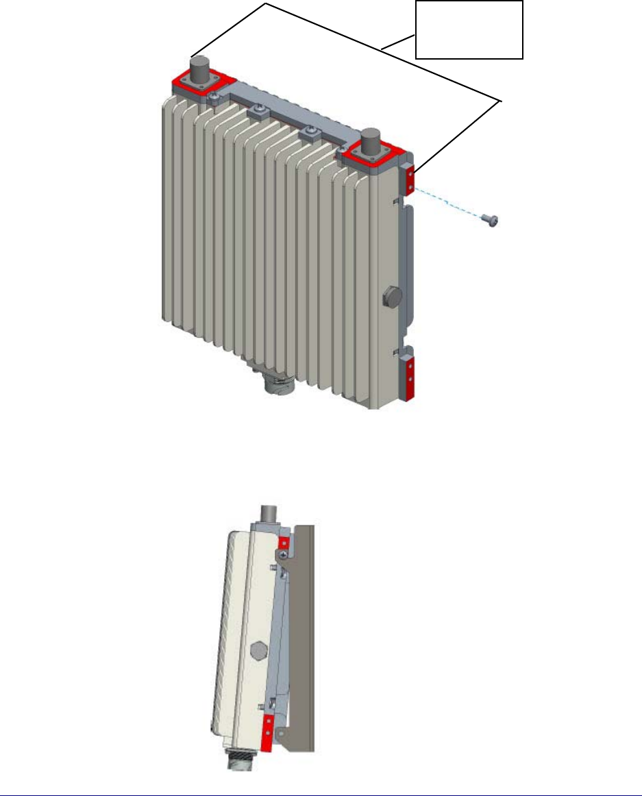
3Insert two screws into the upper holes on opposite sides of the RP as shown in the
drawing below.
Insert screws
into the holes
called out – one
on each side.
4
4Hang the RP to the mounting bracket using the installed screws. Align holes at
bottom location of bracket and install two additional screws. Tighten all four
screws.
5
5Insert and tighten the bottom screws through the plate hole into both sides of the
RP.
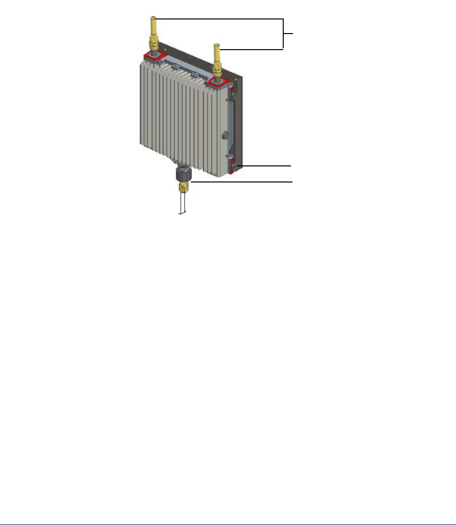
6Connect the antenna couplers on the top of the RP.
7Connect the Ethernet cable RJ45 end to the bottom of the RP.
Installation complete. To configure the RP, see the commissioning procedures in
OneCell Installation and Commissioning (913025).
Antenna couplers
Ethernet connector RJ45
Bottom screw
6
Wall mount installation
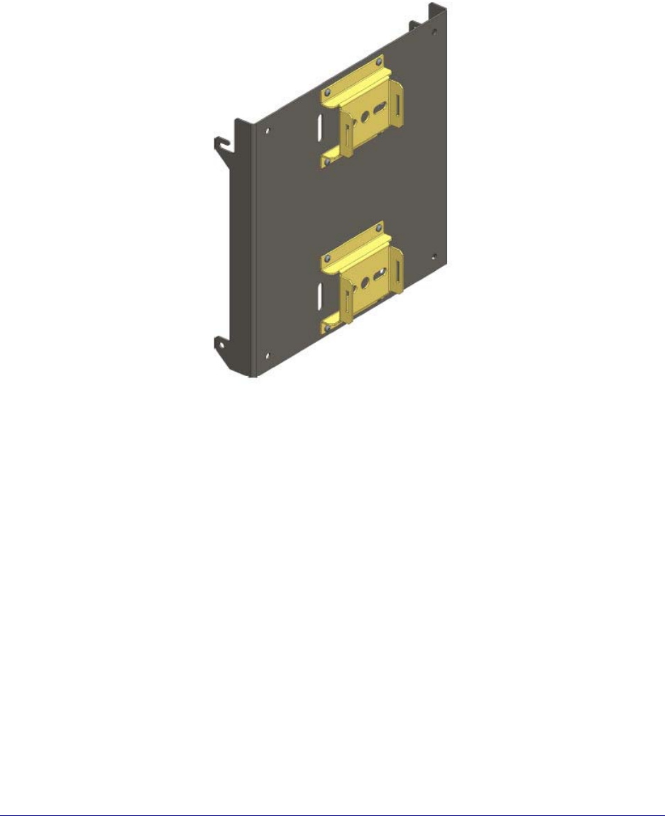
1Remove the brackets from the back of the mounting plate.
7
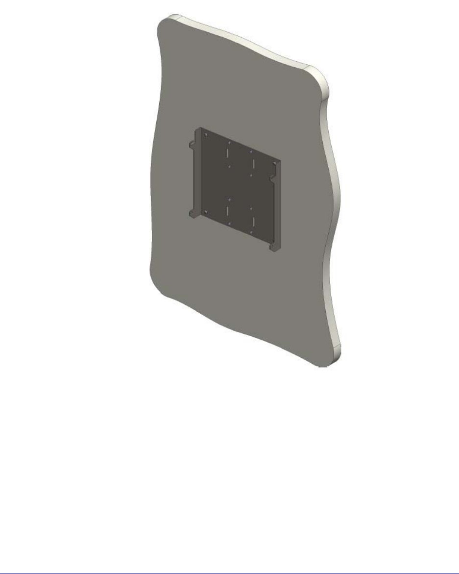
2Drill four holes in the wall using the mounting plate to determine the hole
locations. Mount the backplate on the wall with four molly screws.
8
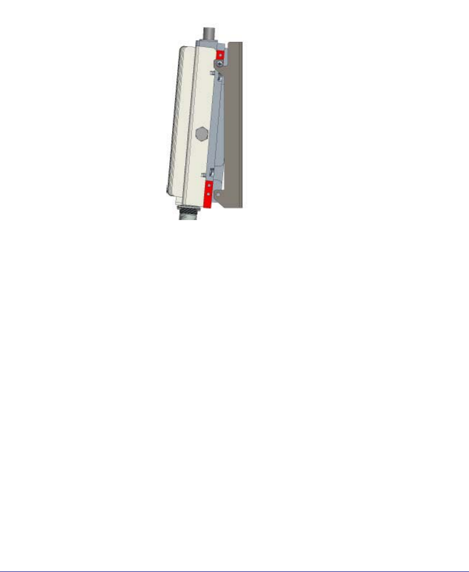
3Insert two screws into the upper holes on opposite sides of the RP as shown in the
drawing below.
4Attach the RP to the mounting plate. Tighten the screws on the RP.
Insert screws
into the holes
called out – one
on each side.
9
5Insert and tighten the bottom screws through the plate hole into both sides of the
RP.
6Connect the antenna couplers on the top of the RP.
7Connect the Ethernet cable RJ45 end to the bottom of the RP.
Installation complete. To configure the RP, see the commissioning procedures in
OneCell Installation and Commissioning (913025).
Antenna couplers
Ethernet connector RJ45
Bottom screw