Compare Electronics CP318 Wireless USB module User Manual CP318 V2 2 SPEC
Shenzhen Compare Electronics Co.,Ltd. Wireless USB module CP318 V2 2 SPEC
Users manual


462
14
SHENZHEN COMPARE ELECTRONICS CO., LTD.
深圳市宝安区西乡街道固戍朱坳工业园中泰工业区D栋7楼
TEL:0755-29063503 FAX:0755-29063506
网址:www.szcompare.com 邮编:518040
OMPARE
1 Introduction
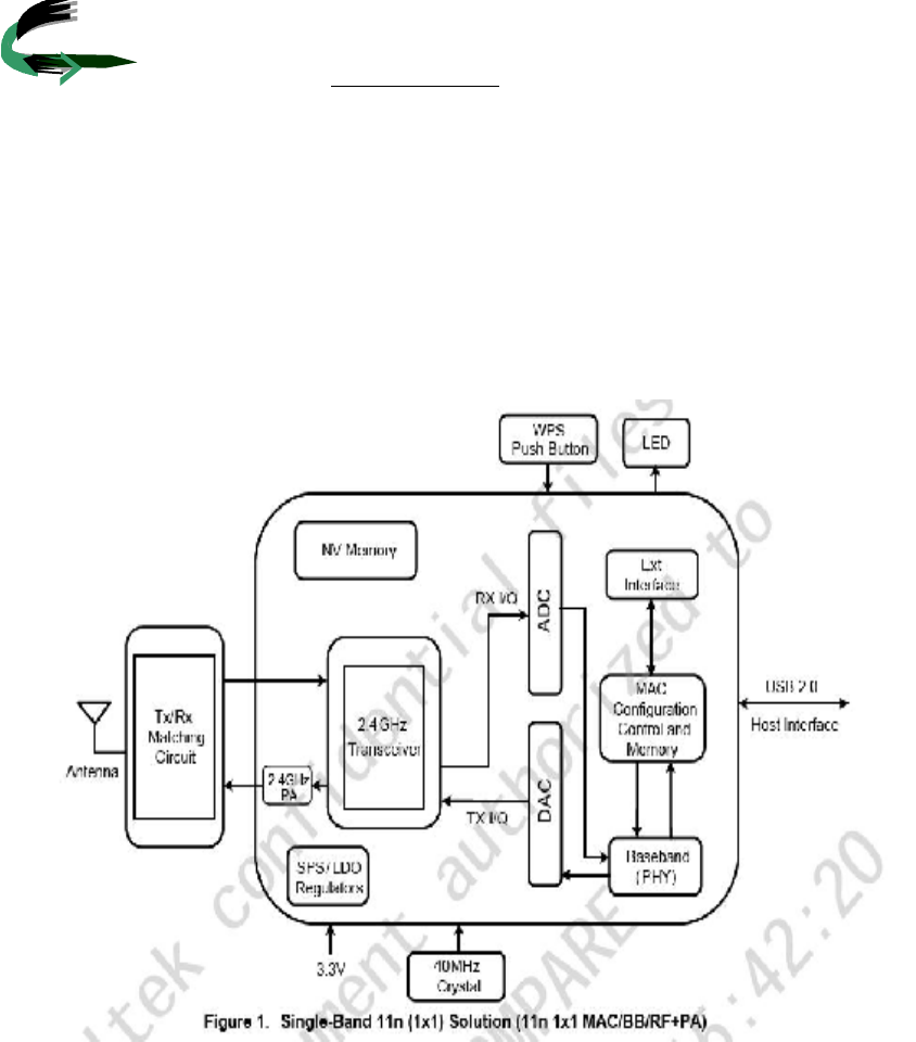
CP318 is a WLAN module supporting IEEE 802.11 b/g/n standards with PH
connector supporting USB 2.0 signaling. This is a low cost compact WLAN module,
designed in the product with embedded system for the wireless connectivity.
CP318 both support RTL8188CUS
1.1 Scope:
CP318 WLAN Module is designed to operate in 2.4GHz ISM frequency
band. This Module complies with IEEE 802.11b/g/n standards.
1.2 Features
Ÿ 1T1R mode with 150Mbps with PHY rates for both transmit and receiving
Dynamic data rate: Maximum data rate up to 150Mbps. 11n: Legacy, Mixed
and Green Field modes, 11g: 54/48/36/24/12/9/6 Mbps (Auto Sensing);
11b:11/5.5/2/1 Mbps (Auto Sensing)
Ÿ support 20MHz/40MHz Bandwidth
Ÿ Security support for 64/128 bit WEP, WPA/WPA2, WPA-PSK/WPA2-PSK
(TKIP/AES)
Ÿ Reverse Direction Grant Data Flow and Frame Aggregation
Ÿ Cisco CCX Support
Ÿ USB2.0
Ÿ Operating Frequency 2.412GHz~ 2. GHz
Ÿ Transmit Output Power: 802.11g/n 14+/-1dBm 802.11b +/-1dBm
Ÿ Receive Sensitivity 11b: -75dBm @ 11Mbps (Typical);11g: -65dBm @
54Mpbs (Typical)
Ÿ Antenna can choose external
Ÿ Operating Voltage 3.3VDC± 5%
Ÿ Antenna Port Impedance 50ohm

15d15d15d
SHENZHEN COMPARE ELECTRONICS CO., LTD.
深圳市宝安区西乡街道固戍朱坳工业园中泰工业区D栋7楼
TEL:0755-29063503 FAX:0755-29063506
网址:www.szcompare.com 邮编:518040
OMPARE
2. General Specification
Model Name CP 318
Standard 802.11b/g/n
Data Transfer Rate 1,2,5.5,6,11,12,18,22,24,30,36,48,54,60,90.120and
maximum of 150Mbps
Modulation Method BPSK/QPSK/16-QAM/64-QAM
Frequency Band 2.4GHz ISM Band
Spread Spectrum
IEE 802.11b:DSSS(Direct Sequence Spectrum)
IEE802.11g/n:OFDM(Orthogonal Frequency
Division Multiplexing)
RF Output Power <Bm@11n ,<Bm @11g,<Bm@11b
Operation Mode Ad hoc, Infrastructure
Receiver Sensitivity 11Mbps-80dbm@8%,54Mbps-70dBm@10%,
130Mbps-64dbm@10%
Operation Range Up to 180 meters in open space
LED Power
OS Support Windows xp/ vista/Win7/Mac /Linux
Security WEP,TKIP,AES,WPA,WPA2
Interface USB 2.0
Power Consumption
DC3.3V
Transmit + Receive: average120mA(3.3V) power
consumption 0.4W
Operating Temperature 0~55℃
Storage Temperature -20℃~70℃
Operating Humidity 10%~90% non-condensing
Storage Humidity 5%~90% non-condensing
Dimensions 25x12x2.2mm(LxwxH)
SHENZHEN COMPARE ELECTRONICS CO., LTD.
深圳市宝安区西乡街道固戍朱坳工业园中泰工业区D栋7楼
TEL:0755-29063503 FAX:0755-29063506
网址:www.szcompare.com 邮编:518040
OMPARE
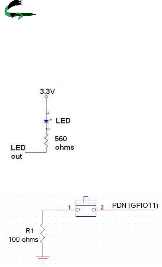
5.1The externalcircuit forWiFiactivityLEDdisplay
5.2 usesa pushor toggleswitch. r-down functioninput(optional)The external
circuit forpower
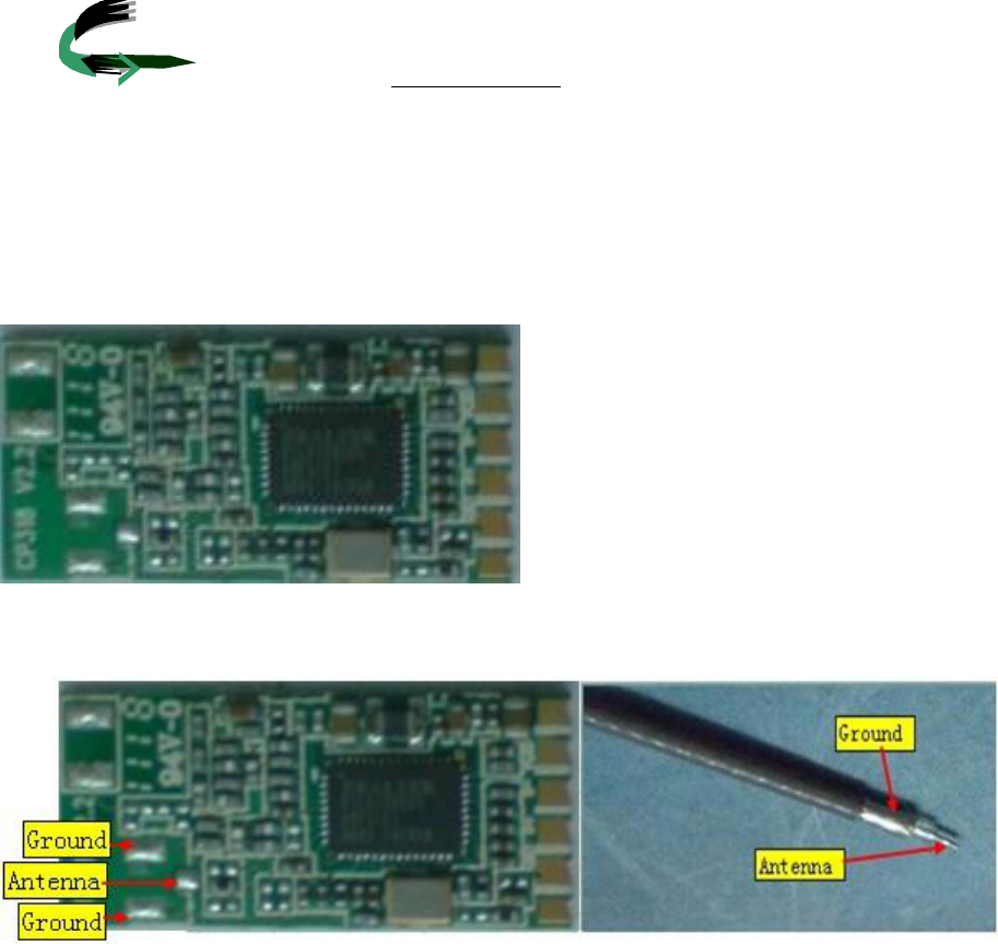
6.AntennaConnection Information
Antenna can choose external
SHENZHEN COMPARE ELECTRONICS CO., LTD.
深圳市宝安区西乡街道固戍朱坳工业园中泰工业区D栋7楼
TEL:0755-29063503 FAX:0755-29063506
网址:www.szcompare.com 邮编:518040
OMPARE
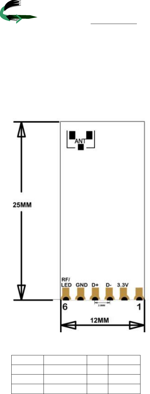
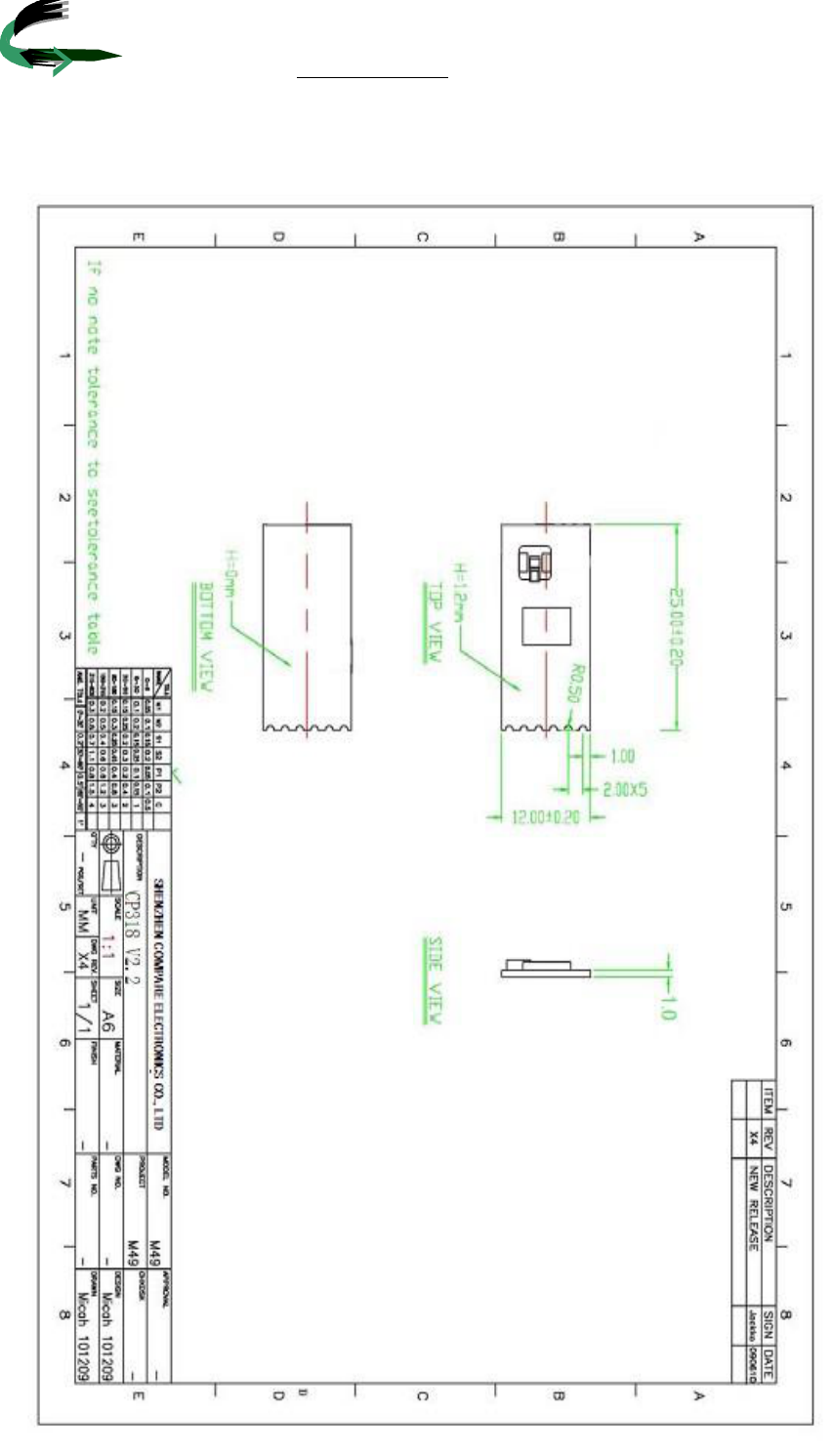
7. Mechanical Information
7.1Dimensions
Size: 25mm(Length)x12mm (Width)
MechanicalDrawing:
PinDefinition
1 5 GND
2 3.3V 6 RF/LED
3 D-
4 D+
7.2USB ConnectionInformation
6inintoin=2.0mm
ppp
modular could be only used in mobile or fix device,
2.Changes or modifications not expressly approved by the party
1.This device complies with Part 15 of the FCC Rules. Operation is subject
FCC STATEMENT
Part 15.19
1. This device complies with Part 15 of the FCC Rules. Operation is subject to the following two
conditions:
(1) This device may not cause harmful interference.
(2) This device must accept any interference received, including interference that may cause
undesired operation.
Part 15.21
2. Changes or modifications not expressly approved by the party responsible for compliance could
void the user's authority to operate the equipment.
When the module is installed inside another device, the user manual
of this device must contain below warning statements;
to the following two conditions:
(1) This device may not cause harmful interference.
(2) This device must accept any interference received, including interference
that may cause undesired operation.
responsible for compliance could void the user's authority to operate the equipment.
This modular could be installed in the fix or mobile devices only, installed in
the portable device, like USB dongle like transmitters is forbidden.
This modular complies with FCC RF radiation exposure limits set forth for
an uncontrolled environment. This transmitter must not be co-located or
operating in conjunction with any other antenna or transmitter. This modular must
be installed and operated with a minimum distance of 20 cm between the
radiator and user body.
Regulatory Information
The devices must be installed and used in strict accordance with the
manufacturer's instructions as described in the user documentation that
comes with the product.
and could not be used in any portable device.
Part 15.105
NOTE: This equipment has been tested and found to comply with the limits for a Class B digital
device, pursuant to Part 15 of the FCC Rules. These limits are designed to provide reasonable
protection against harmful interference in a residential installation.
This equipment generates uses and can radiate radio frequency energy and, if not installed and
used in accordance with the instructions, may cause harmful interference to radio communications.
However, there is no guarantee that interference will not occur in a particular installation. If this
equipment does cause harmful interference to radio or television reception, which can be
determined by turning the equipment off and on, the user is encouraged to try to correct the
interference by one or more of the following measures:
Reorient or relocate the receiving antenna.
Increase the separation between the equipment and receiver.
Connect the equipment into an outlet on a circuit different from that to which the receiver is
connected.
Consult the dealer or an experienced radio/TV technician for help.
If the FCC identification number is not visible when the module
is installed inside another device, then the outside of the device
into which the module is installed must also display a label
referring to the enclosed module. This exterior label can use
wording such as the following: “Contains Transmitter Module
FCC ID: A2TCP318