Comtrend 5374 Multi DSL Wireless Router User Manual UM CT 5374 A2 0
Comtrend Corporation Multi DSL Wireless Router UM CT 5374 A2 0
Comtrend >
Contents
- 1. Users Manual 1 of 3
- 2. User manual 2 of 3
- 3. User manual 3 of 3
User manual 3 of 3
100
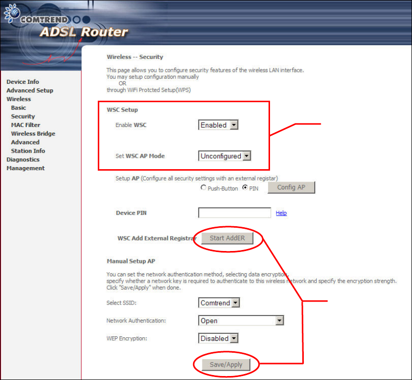
Step 3: On the Wireless Security screen, enable WSC by selecting Enabled
from the drop down list box and set the WSC AP Mode to Unconfigured.
101
Step 4: Click the Save/Apply button at the bottom of the screen. The screen
will go blank while the router applies the new Wireless settings. When
the screen returns, press the Start AddER button, as shown above.
Step 3
Step 4
102
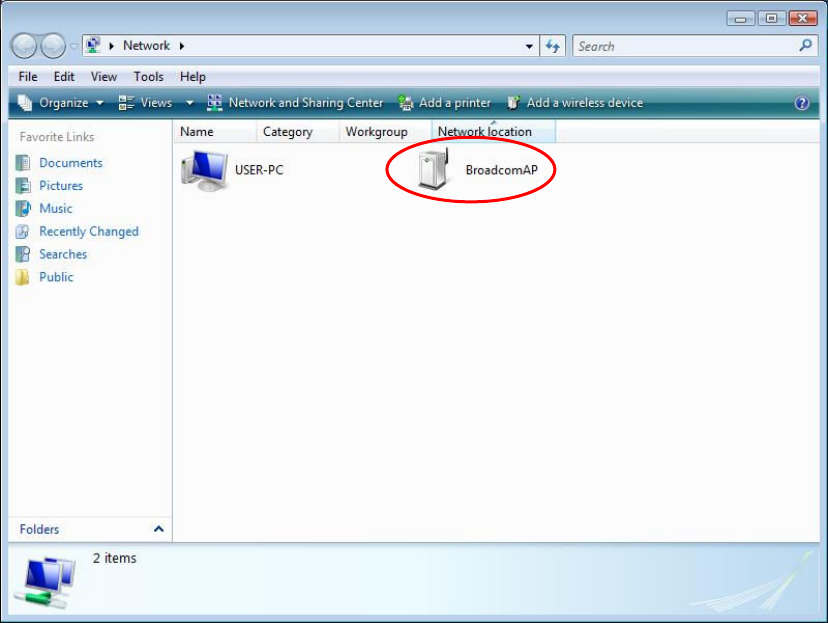
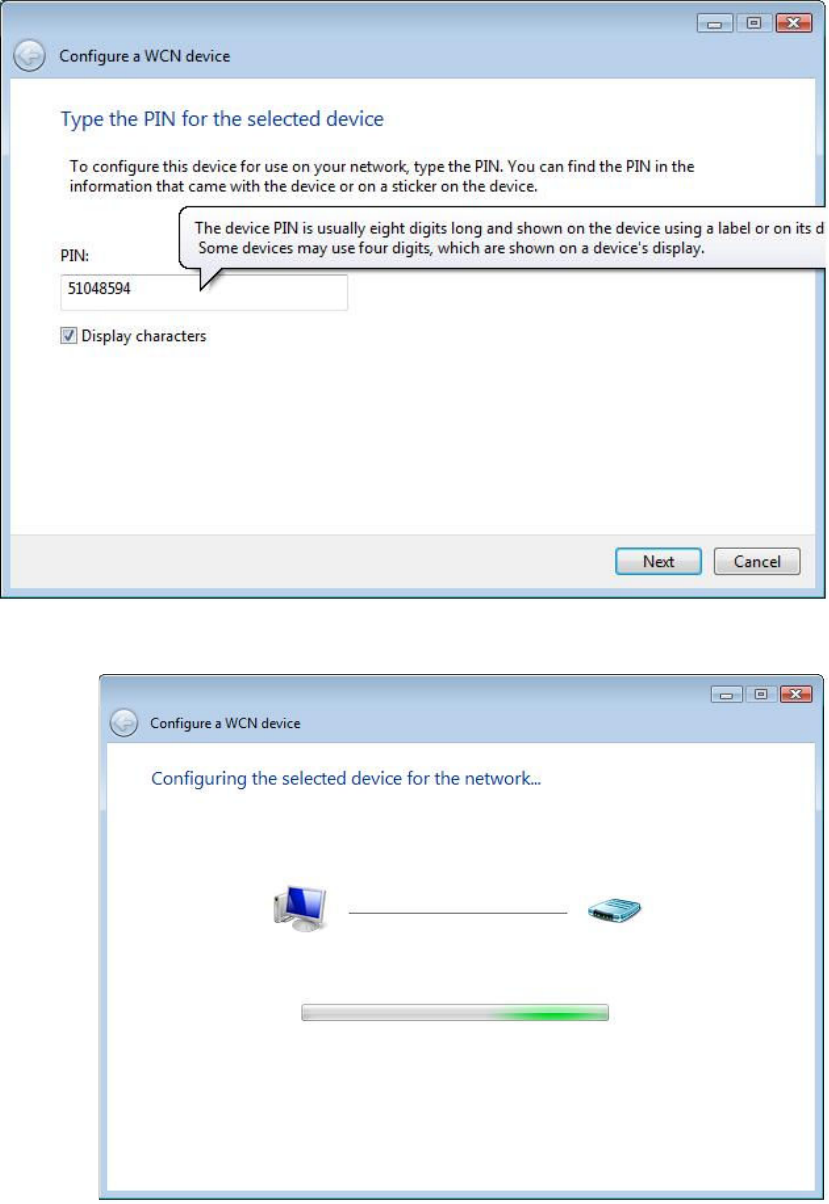
Step 5: Now return to the Network folder and click the BroadcomAP icon. A
dialog box will appear asking for the Device PIN number. Enter the
Device PIN as shown on the Wireless Security screen. Click Next.
Step 6: Windows Vista will attempt to configure the wireless security settings.
Step 7: If successful, the security settings will match those in Windows Vista.
103
Appendix F - Printer Server
These steps explain the procedure for enabling the Printer Server.
NOTE: This function only applies to models with an USB host port.
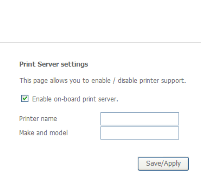
STEP 1: Enable Print Server from Web User Interface. Select Enable on-board
print server checkbox and enter Printer name and Make and model
NOTE: The Printer name can be any text string up to 40 characters.
The Make and model can be any text string up to 128 characters.
104
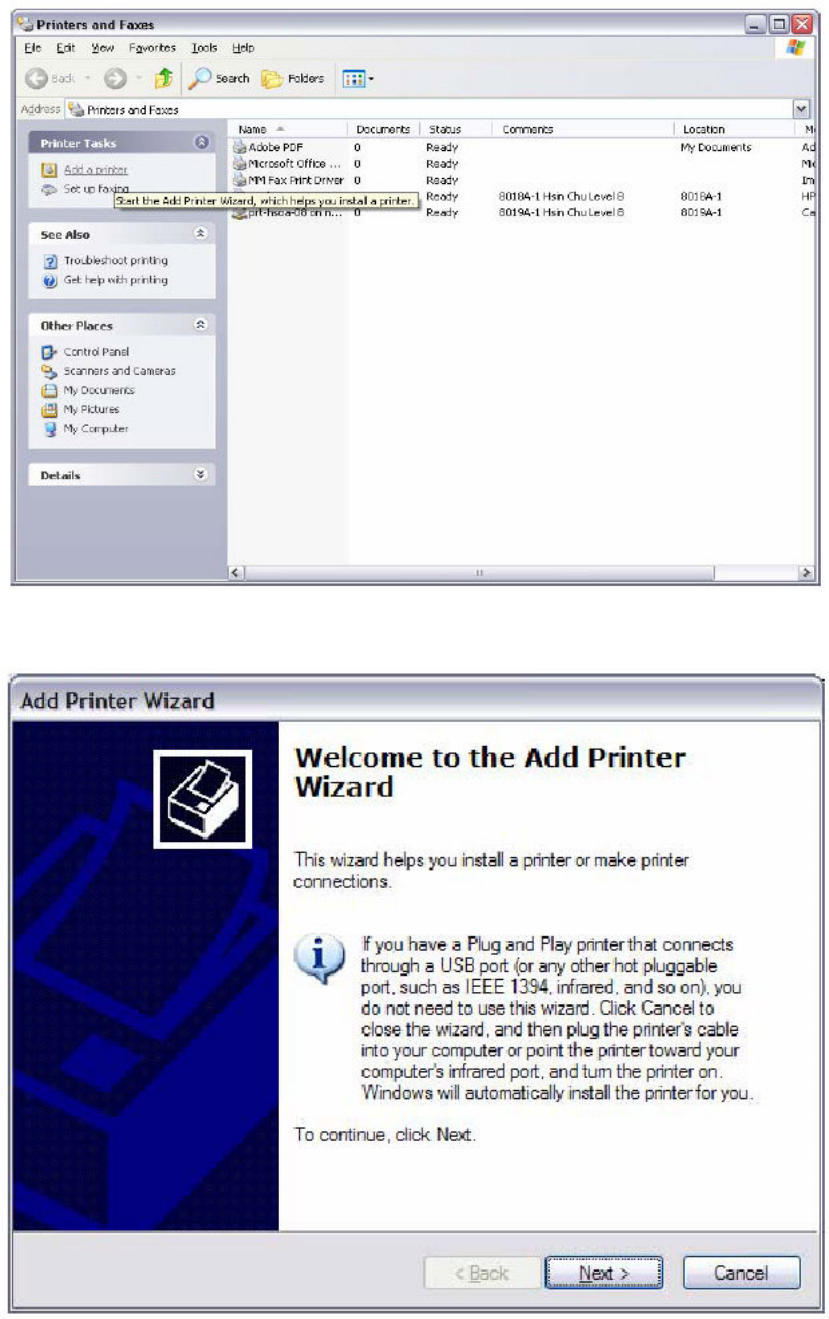
STEP 2: Go to the Printers and Faxes application in the Control Panel and
select the Add a printer function (as located on the side menu below).
STEP 3: Click Next to continue when you see the dialog box below.
105
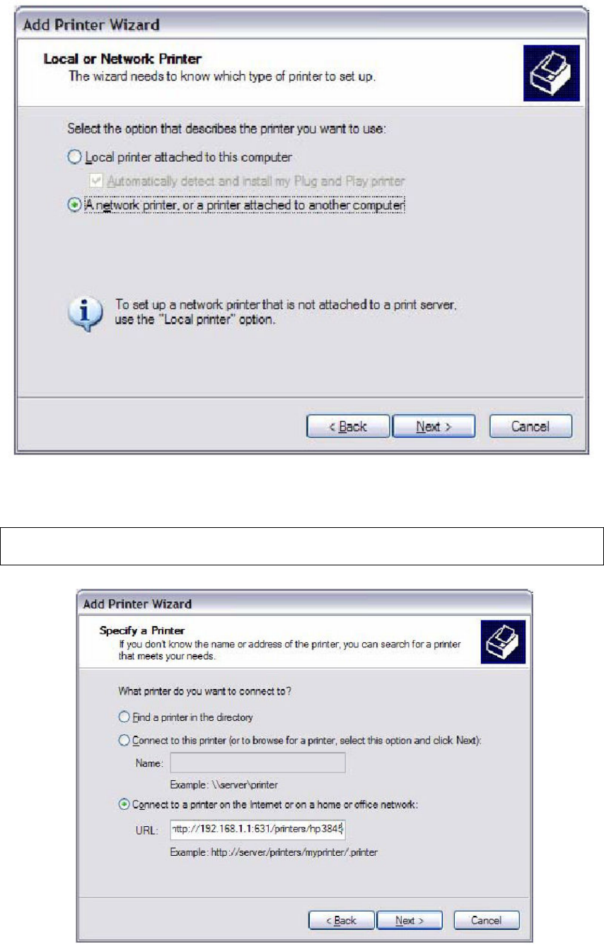
STEP 4: Select Network Printer and click Next.
STEP 5: Select Connect to a printer on the Internet and enter your printer link.
(e.g. http://192.168.1.1:631/printers/hp3845) and click Next.
NOTE: The printer name must be the same name entered in the ADSL modem
WEB UI “printer server setting” as in step 1.
106
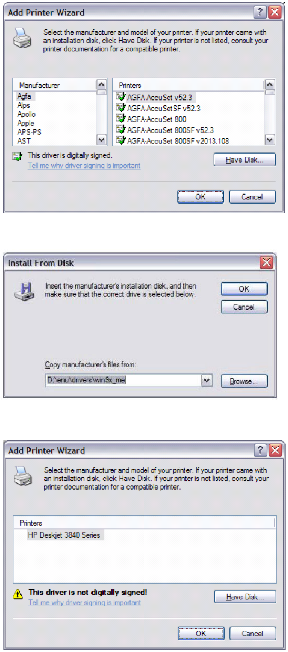
STEP 6: Click Have Disk and insert the printer driver CD.
STEP 7: Select driver file directory on CD-ROM and click OK.
STEP 8: Once the printer name appears, click OK.
107
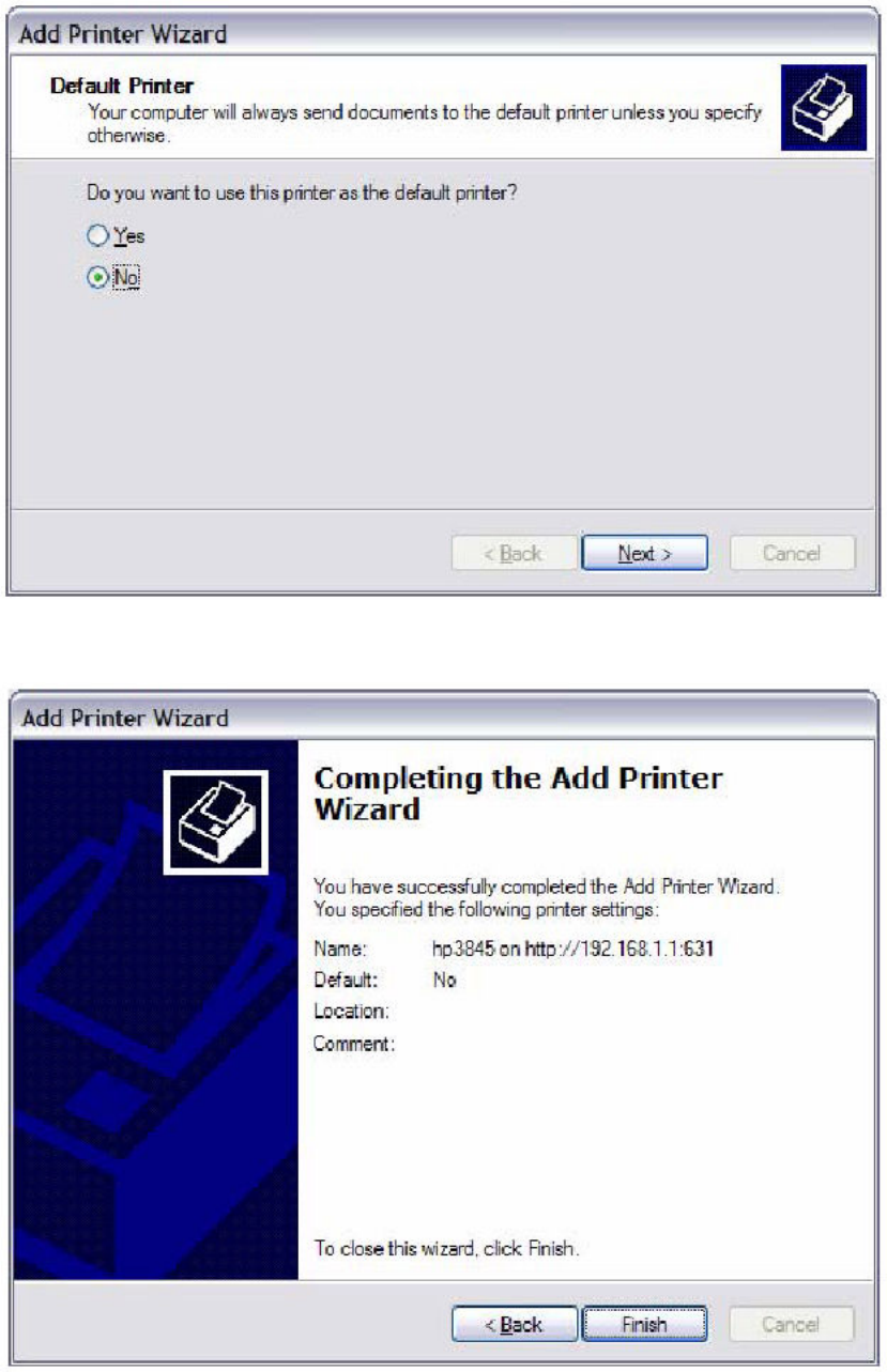
STEP 9: Choose Yes or No for default printer setting and click Next.
STEP 10: Click Finish.
108
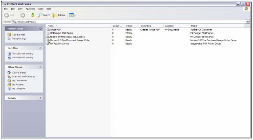
STEP 11: Check the status of printer from Windows Control Panel, printer window.
Status should show as Ready.
109
Appendix G - Connection Setup
Creating a WAN connection is a two-stage process.
1 - Setup a Layer 2 Interface (ATM, PTM or Ethernet).
2 - Add a WAN connection to the Layer 2 Interface.
The following sections describe each stage in turn.
G1 ~ Layer 2 Interfaces
Every layer2 interface operates in one of three modes: Default, VLAN Mux or MSC.
A short introduction to each of these three modes is included below for reference.
It is important to understand the differences between these connection modes, as
they determine the number and types of connections that may be configured.
DEFAULT MODE
In this mode there is a 1:1 relationship between interfaces and WAN connections, in
that an interface in default mode supports just one connection. However, unlike the
multiple connection modes described below, it supports all five connection types.
The figure below shows the five connection types available in ATM default mode.
VLAN MUX MODE
This mode uses VLAN tags to allow for multiple connections over a single interface.
PPPoE, IPoE, and Bridge are supported while PPPoA and IPoA connections are not.
The figure below shows multiple connections over a single VLAN Mux interface.
MSC MODE
Multi-Service Connection (MSC) mode supports multiple connections over a single
interface. As with VLAN Mux mode, PPPoA and IPoA connection types are not
supported, while Bridging is unavailable for Ethernet WAN interfaces. After adding
WAN connections to an interface, you must also create an Interface Group to
connect LAN/WAN interfaces (see section G3 ~ More About MSC Mode).
110
G1.1 ATM Interfaces
Follow these procedures to configure an ATM interface.
NOTE: The CT-5374 supports up to 16 ATM interfaces.
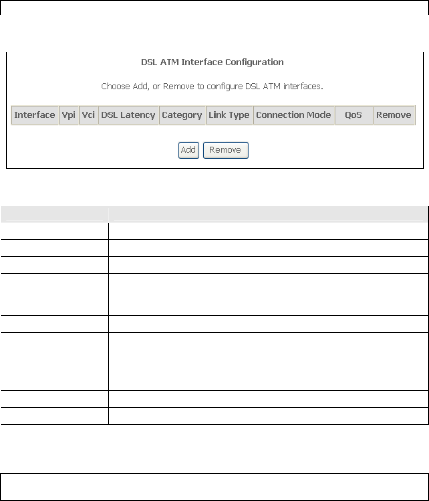
STEP 1: Go to Advanced Setup Layer2 Interface ATM Interface.
This table is provided here for ease of reference.
Heading Description
Interface WAN interface name.
VPI ATM VPI (0-255)
VCI ATM VCI (32-65535)
DSL Latency {Path0} portID = 0
{Path1} port ID = 1
{Path0&1} port ID = 4
Category ATM service category
Link Type Choose EoA (for PPPoE, IPoE, and Bridge), PPPoA, or IPoA.
Connection Mode Default Mode – Single service over one connection
Vlan Mux Mode – Multiple Vlan service over one connection
MSC Mode – Multiple Service over one Connection
QoS Quality of Service (QoS) status
Remove Select items for removal
STEP 2: Click Add to proceed to the next screen.
NOTE: To add WAN connections to one interface type, you must delete existing
connections from the other interface type using the remove button.
111
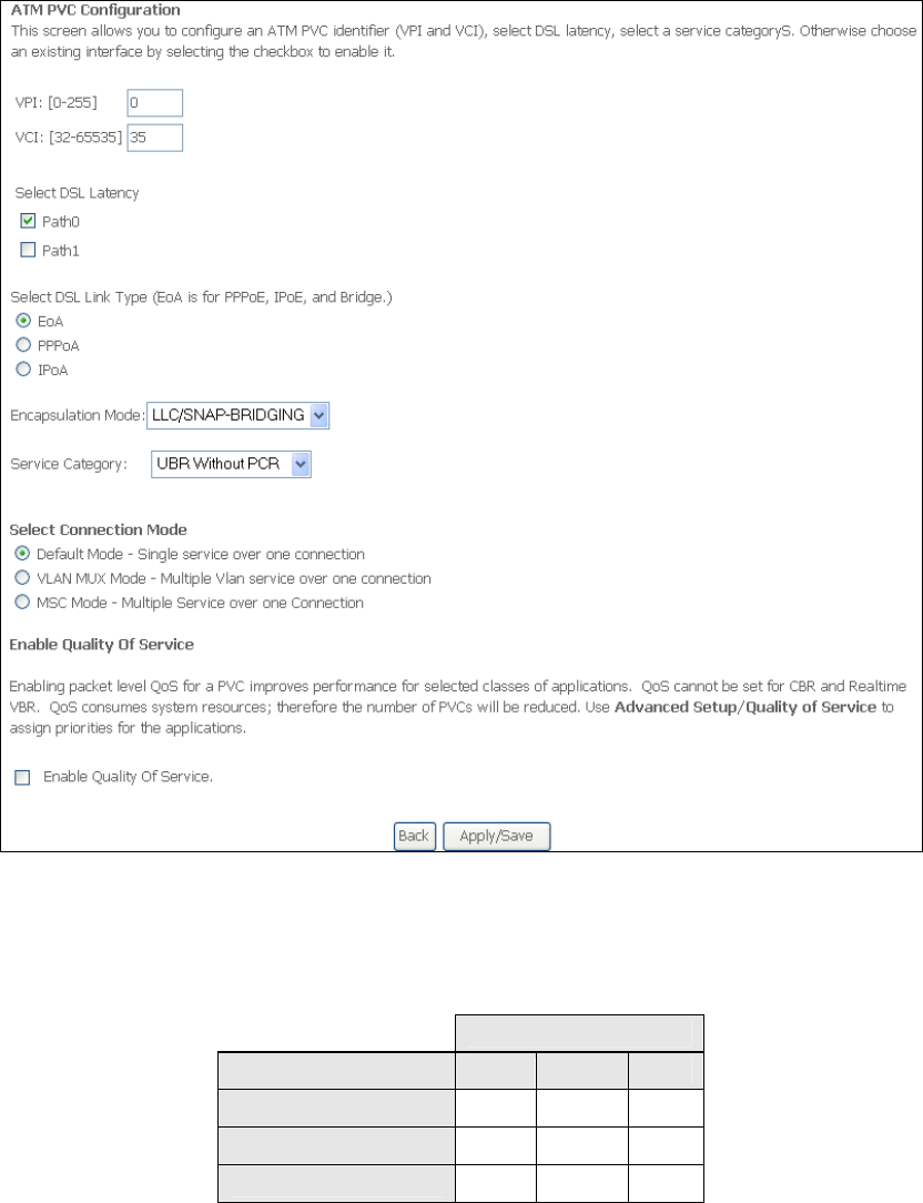
There are many settings here including: VPI/VCI, DSL Latency, DSL Link Type,
Encapsulation Mode, Service Category, Connection Mode and Quality of Service.
The table below shows xDSL Link Type availability with each Connection Mode.
xDSL Link Type
Connection Mode
EoA*
PPPoA
IPoA
Default Mode
OK OK OK
VLAN Mux Mode
OK X X
MSC Mode
OK X X
* EoA includes PPPoE, IPoE, and Bridge link types.
Here are the available encapsulations for each xDSL Link Type:
EoA- LLC/SNAP-BRIDGING, VC/MUX
PPPoA- VC/MUX, LLC/ENCAPSULATION
IPoA- LLC/SNAP-ROUTING, VC MUX
STEP 3: Click Apply/Save to confirm your choices.
112
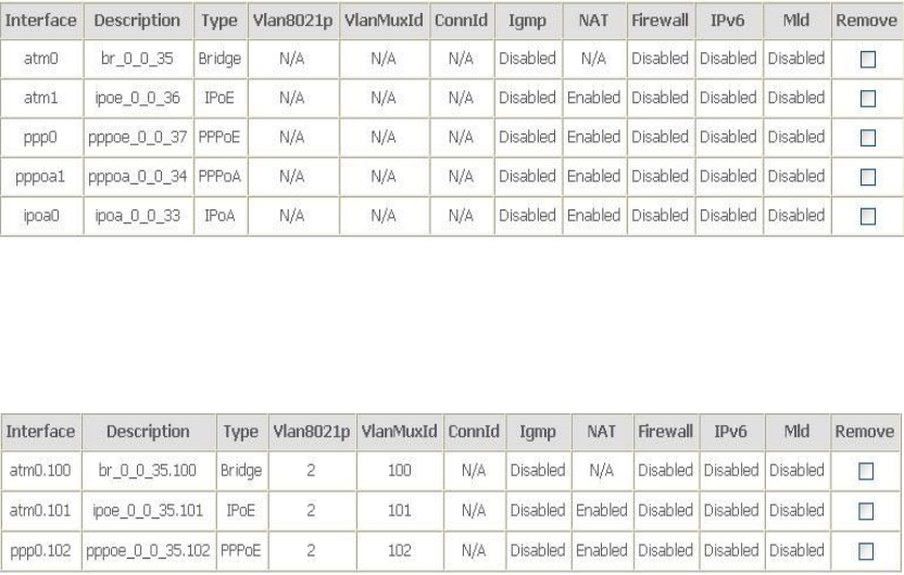
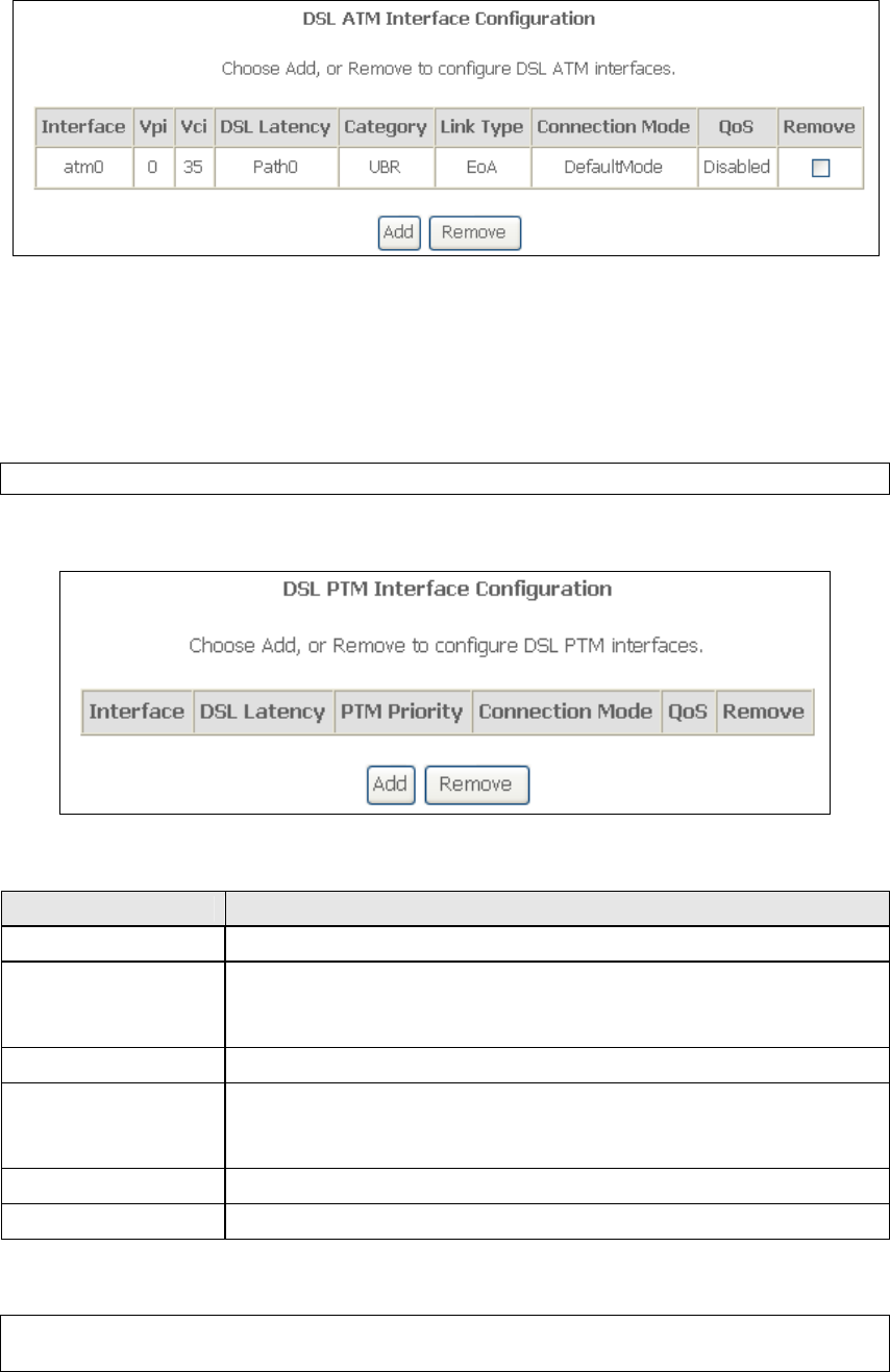
On the next screen, check that the ATM interface is added to the list. For example,
an ATM interface on PVC 0/35 in Default Mode with an EoA Link type is shown below.
To add a WAN connection, go to section G2 ~ WAN Connections.
G1.2 PTM Interfaces
Follow these procedures to configure a PTM interface.
NOTE: The CT-5374 supports up to four PTM interfaces.
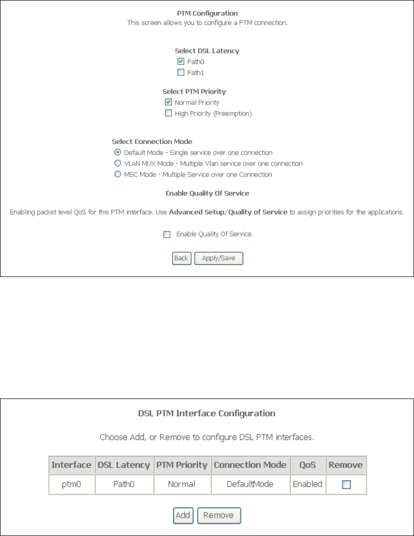
STEP 4: Go to Advanced Setup Layer2 Interface PTM Interface.
This table is provided here for ease of reference.
Heading Description
Interface WAN interface name.
DSL Latency {Path0} portID = 0
{Path1} port ID = 1
{Path0&1} port ID = 4
PTM Priority Normal or High Priority (Preemption).
Connection Mode Default Mode – Single service over one interface.
Vlan Mux Mode – Multiple Vlan services over one interface.
MSC Mode – Multiple Services over one interface.
QoS Quality of Service (QoS) status.
Remove Select interfaces to remove.
STEP 5: Click Add to proceed to the next screen.
NOTE: To add WAN connections to one interface type, you must delete existing
connections from the other interface type using the remove button.
113
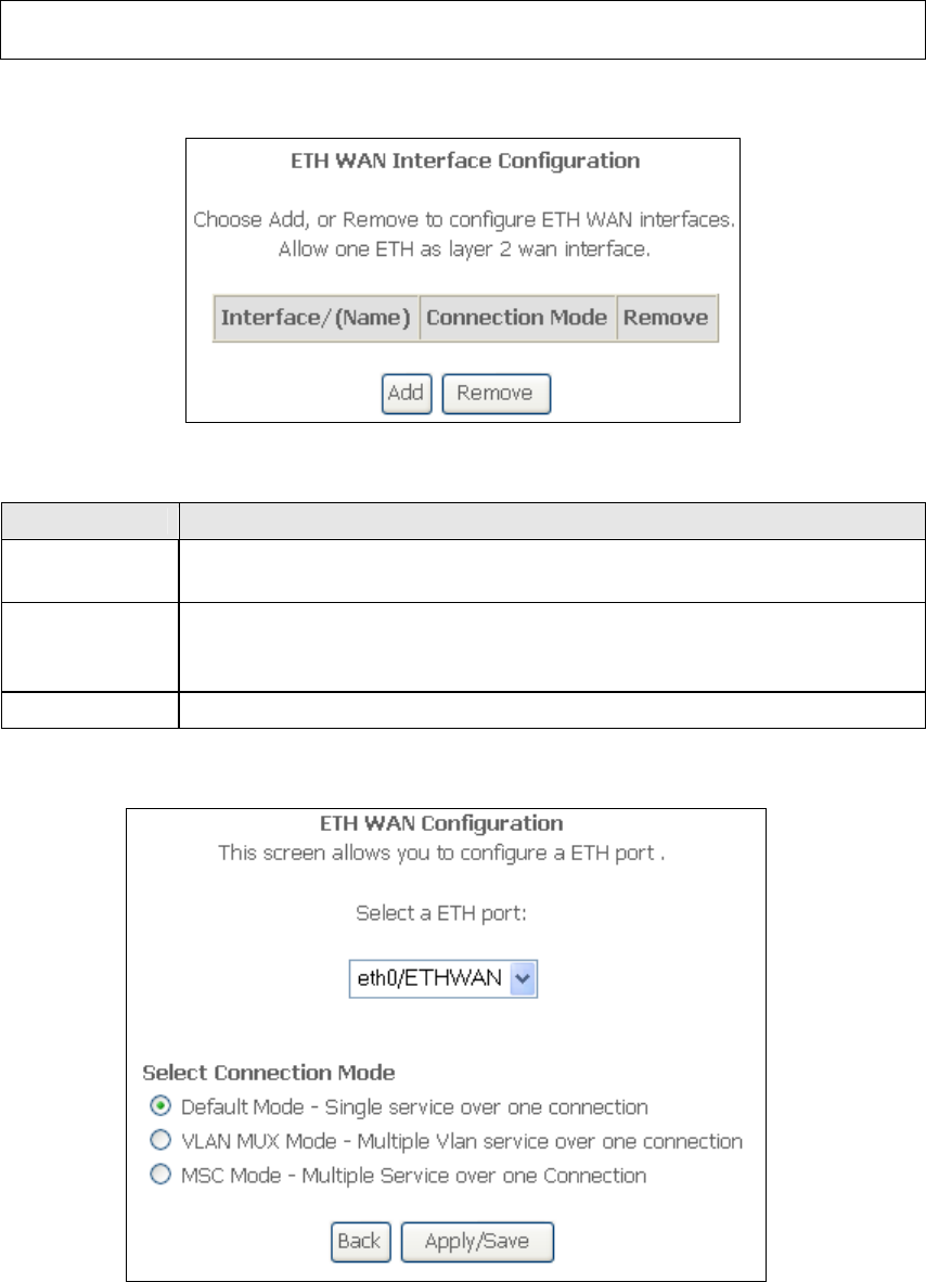
There are many settings that can be configured here including:
DSL Latency, PTM Priority, Connection Mode and Quality of Service.
STEP 6: Click Apply/Save to confirm your choices.
On the next screen, check that the PTM interface is added to the list.
For example, an PTM interface in Default Mode is shown below.
To add a WAN connection, go to section G2 ~ WAN Connections.
G1.3 Ethernet WAN Interface
Some models of the CT-5374 support a single Ethernet WAN interface over the ETH
WAN port. Follow these procedures to configure an Ethernet WAN interface.
114
NOTE: To add WAN connections to one interface type, you must delete existing
connections from the other interface type using the remove button.
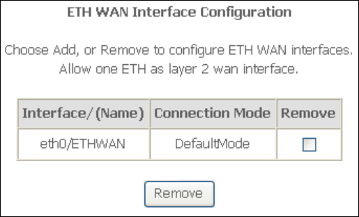
STEP 1: Go to Advanced Setup Layer2 Interface ETH Interface.
This table is provided here for ease of reference.
Heading Description
Interface/
(Name)
ETH WAN Interface
Connection
Mode
Default Mode – Single service over one connection
Vlan Mux Mode – Multiple Vlan service over one connection
MSC Mode – Multiple Service over one Connection
Remove Select the checkbox and click Remove to remove the connection.
STEP 2: Click Add to proceed to the next screen.
STEP 3: Select a Connection Mode from the options shown above.
STEP 4: Click Apply/Save to confirm your choice.
The figure below shows an Ethernet WAN interface configured in Default Mode.
115
To add a WAN connection, go to section G2 ~ WAN Connections.
116
G2 ~ WAN Connections
In Default Mode, the CT-5374 supports one WAN connection for each interface, up
to a maximum of 8 connections. VLAN Mux and MSC support up to 16 connections.
To setup a WAN connection follow these instructions.
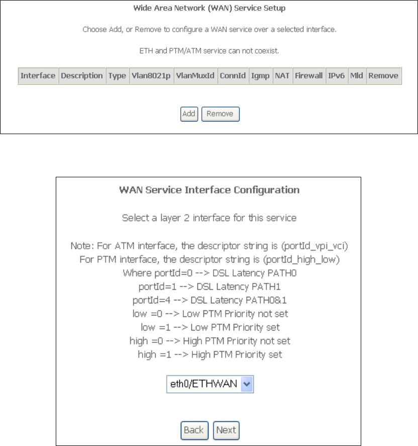
STEP 1: Go to the Advanced Setup WAN Service screen.
STEP 2: Click Add to create a WAN connection. The following screen will display.
117
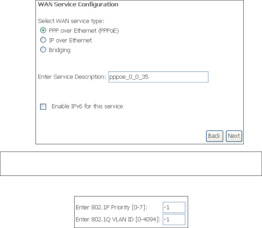
STEP 3: Choose a layer 2 interface from the drop-down box and click Next.
The WAN Service Configuration screen will display as shown below.
NOTE: The WAN services shown here are those supported by the layer 2
interface you selected in the previous step. If you wish to change your
selection click the Back button and select a different layer 2 interface.
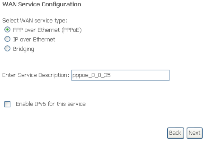
STEP 4: For VLAN Mux Connections only, you must enter Priority & VLAN ID tags.
STEP 5: You will now follow the instructions specific to the WAN service type you
wish to establish. This list should help you locate the correct procedure:
(1) For G2.1 PPP over ETHERNET (PPPoE), go to page 118.
(2) For G2.2 IP over ETHERNET (IPoE), go to page 123.
(3) For G2.3 Bridging, go to page 128.
(4) For G2.4 PPP over ATM (PPPoA), go to page 129.
(5) For G2.5 IP over ATM (IPoA), go to page 134.
The subsections that follow continue the WAN service setup procedure.
118
G2.1 PPP over ETHERNET (PPPoE)
STEP 1: Select the PPP over Ethernet radio button and click Next. You can also
enable IPv6 by ticking the checkbox at the bottom of this screen.
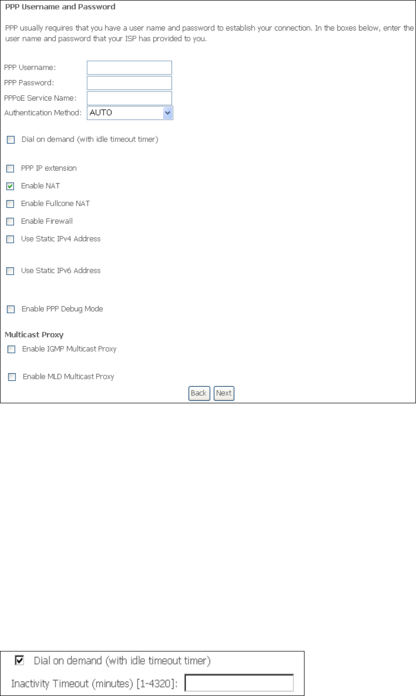
STEP 2: On the next screen, enter the PPP settings as provided by your ISP.
Click Next to continue or click Back to return to the previous step.
119
The settings shown above are described below.
PPP SETTINGS
The PPP Username, PPP password and the PPPoE Service Name entries are
dependent on the particular requirements of the ISP. The user name can be a
maximum of 256 characters and the password a maximum of 32 characters in
length. For Authentication Method, choose from AUTO, PAP, CHAP, and MSCHAP.
ENABLE FULLCONE NAT
This option becomes available when NAT is enabled. Known as one-to-one NAT, all
requests from the same internal IP address and port are mapped to the same
external IP address and port. An external host can send a packet to the internal host,
by sending a packet to the mapped external address.
DIAL ON DEMAND
The CT-5374 can be configured to disconnect if there is no activity for a period of
time by selecting the Dial on demand checkbox . You must also enter an
inactivity timeout period in the range of 1 to 4320 minutes.

120
PPP IP EXTENSION
The PPP IP Extension is a special feature deployed by some service providers.
Unless your service provider specifically requires this setup, do not select it.
PPP IP Extension does the following:
• Allows only one PC on the LAN.
• Disables NAT and Firewall.
• The device becomes the default gateway and DNS server to the PC
through DHCP using the LAN interface IP address.
• The device extends the IP subnet at the remote service provider to the
LAN PC. i.e. the PC becomes a host belonging to the same IP subnet.
• The device bridges the IP packets between WAN and LAN ports, unless
the packet is addressed to the device’s LAN IP address.
• The public IP address assigned by the remote side using the PPP/IPCP
protocol is actually not used on the WAN PPP interface. Instead, it is
forwarded to the PC LAN interface through DHCP. Only one PC on the
LAN can be connected to the remote, since the DHCP server within the
device has only a single IP address to assign to a LAN device.
ENABLE NAT
If the LAN is configured with a private IP address, the user should select this
checkbox . The NAT submenu will appear in the Advanced Setup menu after reboot.
On the other hand, if a private IP address is not used on the LAN side (i.e. the LAN
side is using a public IP), this checkbox should not be selected to free up system
resources for better performance.
ENABLE FIREWALL
If this checkbox is selected, the Security submenu will be displayed on the
Advanced Setup menu after reboot. If firewall is not necessary, this checkbox
should not be selected to free up system resources for better performance.
USE STATIC IPv4 ADDRESS
Unless your service provider specially requires it, do not select this checkbox . If
selected, enter the static IP address in the IPv4 Address field. Don’t forget to
adjust the IP configuration to Static IP Mode as described in 3.2 IP Configuration.
USE STATIC IPv6 ADDRESS
This option displays when IPv6 is enabled. Unless your service provider specially
requires it, do not select this checkbox . If selected, enter the static IP address in
the IPv6 Address field along with a value for Prefix Length. Don’t forget to adjust
the IP configuration to Static IP Mode as described in 3.2 IP Configuration.
ENABLE PPP DEBUG MODE
When this option is selected, the system will put more PPP connection information
into the system log. This is for debugging errors and not for normal usage.
BRIDGE PPPOE FRAMES BETWEEN WAN AND LOCAL PORTS
(This option is hidden when PPP IP Extension is enabled)
When Enabled, this creates local PPPoE connections to the WAN side. Enable this
option only if all LAN-side devices are running PPPoE clients, otherwise disable it.
The CT-5374 supports pass-through PPPoE sessions from the LAN side while
simultaneously running a PPPoE client from non-PPPoE LAN devices.
121
ENABLE IGMP MULTICAST PROXY
Tick the checkbox to enable Internet Group Membership Protocol (IGMP)
multicast. This protocol is used by IPv4 hosts to report their multicast group
memberships to any neighboring multicast routers.
ENABLE MLD MULTICAST PROXY
This option displays when IPv6 is enabled. Tick the checkbox to enable Multicast
Listener Discovery (MLD). This protocol is used by IPv6 hosts to report their
multicast group memberships to any neighboring multicast routers.
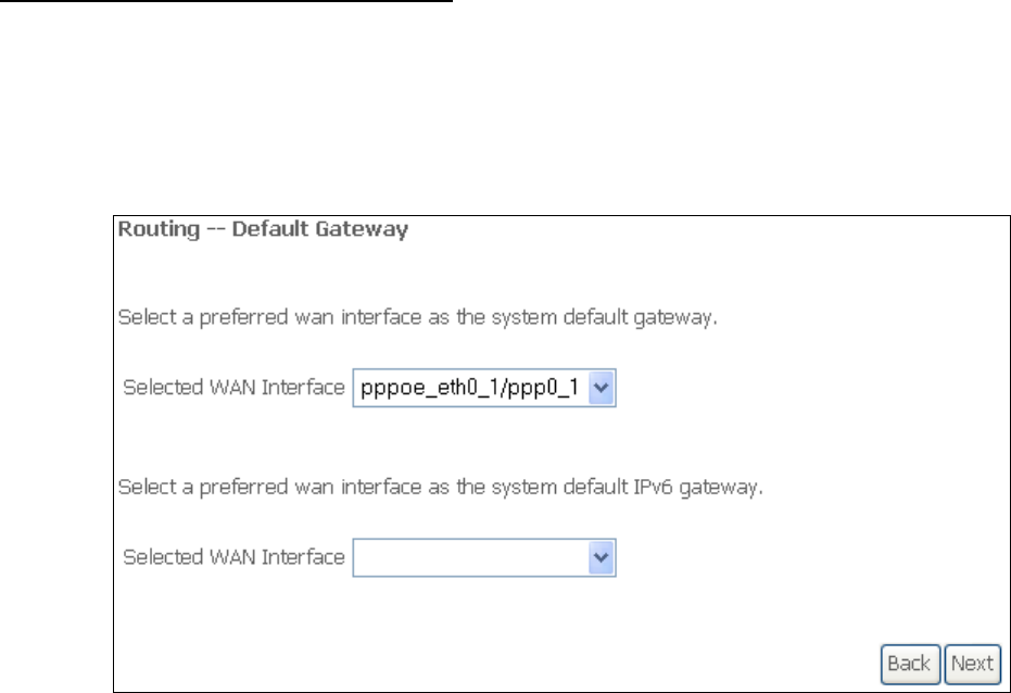
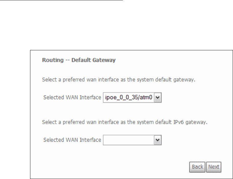
STEP 3: Select WAN interfaces as system default IPv4/v6 gateways. When IPv6 is
enabled a second WAN interface selection box will appear, as shown here.
Click Next to continue or click Back to return to the previous step.
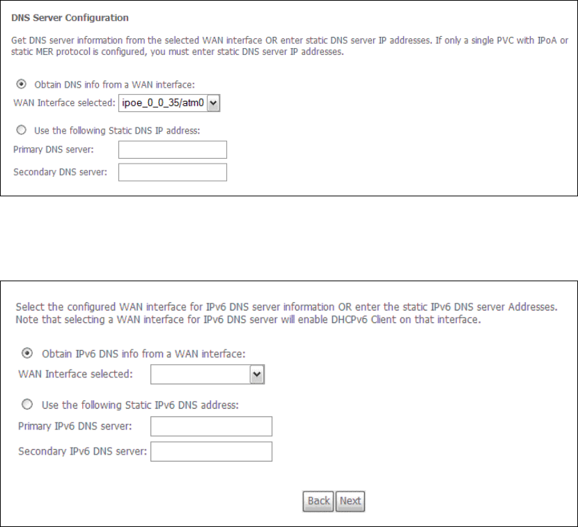
STEP 4: Select a WAN interface or enter static IP address to IPv4/v6 DNS Servers.
When IPv6 is enabled, a second set of entries will appear, as shown here.
122
Click Next to continue or click Back to return to the previous step.
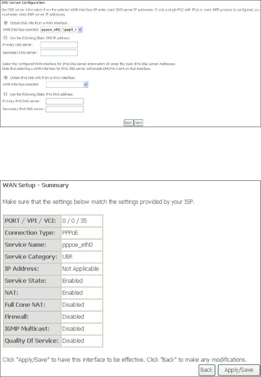
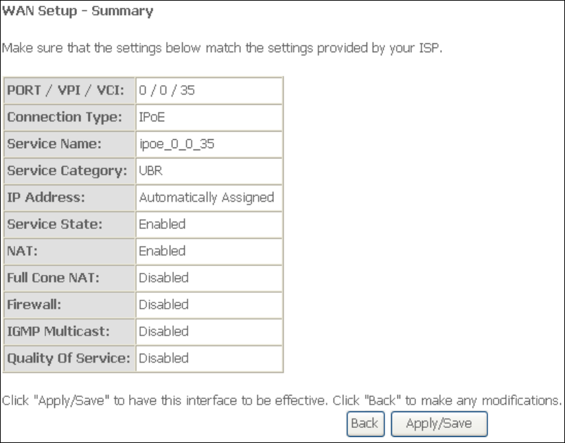
STEP 5: The WAN Setup - Summary screen shows a preview of the WAN service
you have configured. Check these settings and click Apply/Save if they
are correct, or click Back to modify them.
After clicking Apply/Save, the new service should appear on the main screen.
To activate it you must reboot. Go to Management Reboot and click Reboot.
123
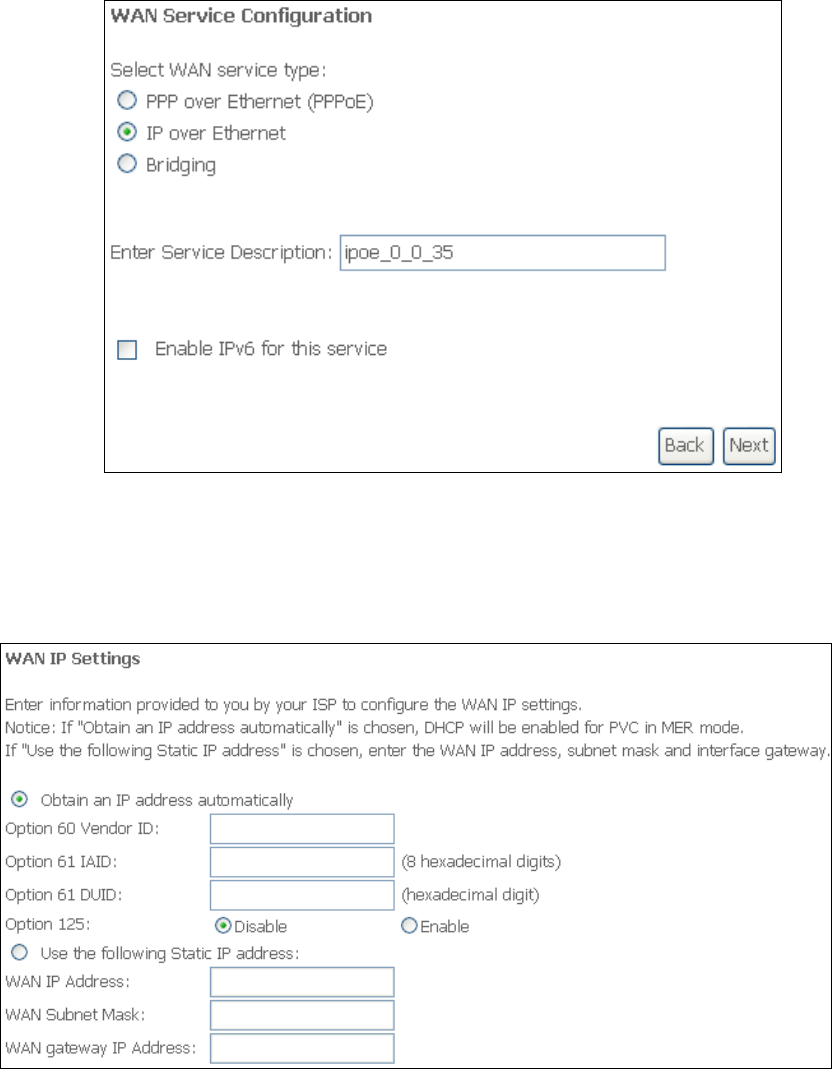
G2.2 IP over ETHERNET (IPoE)
STEP 1: Select the IP over Ethernet radio button and click Next. You can also
enable IPv6 by ticking the checkbox at the bottom of this screen.
STEP 2: The WAN IP settings screen provides access to the DHCP server settings.
You can select the Obtain an IP address automatically radio button to
enable DHCP (use the DHCP Options only if necessary). However, if you
prefer, you can instead use the Static IP address method to assign WAN
IP address, Subnet Mask and Default Gateway manually.
124
NOTE: If IPv6 networking is enabled, an additional set of instructions, radio
buttons, and text entry boxes will appear at the bottom of the screen.
These configuration options are quite similar to those for IPv4 networks.
Click Next to continue or click Back to return to the previous step.
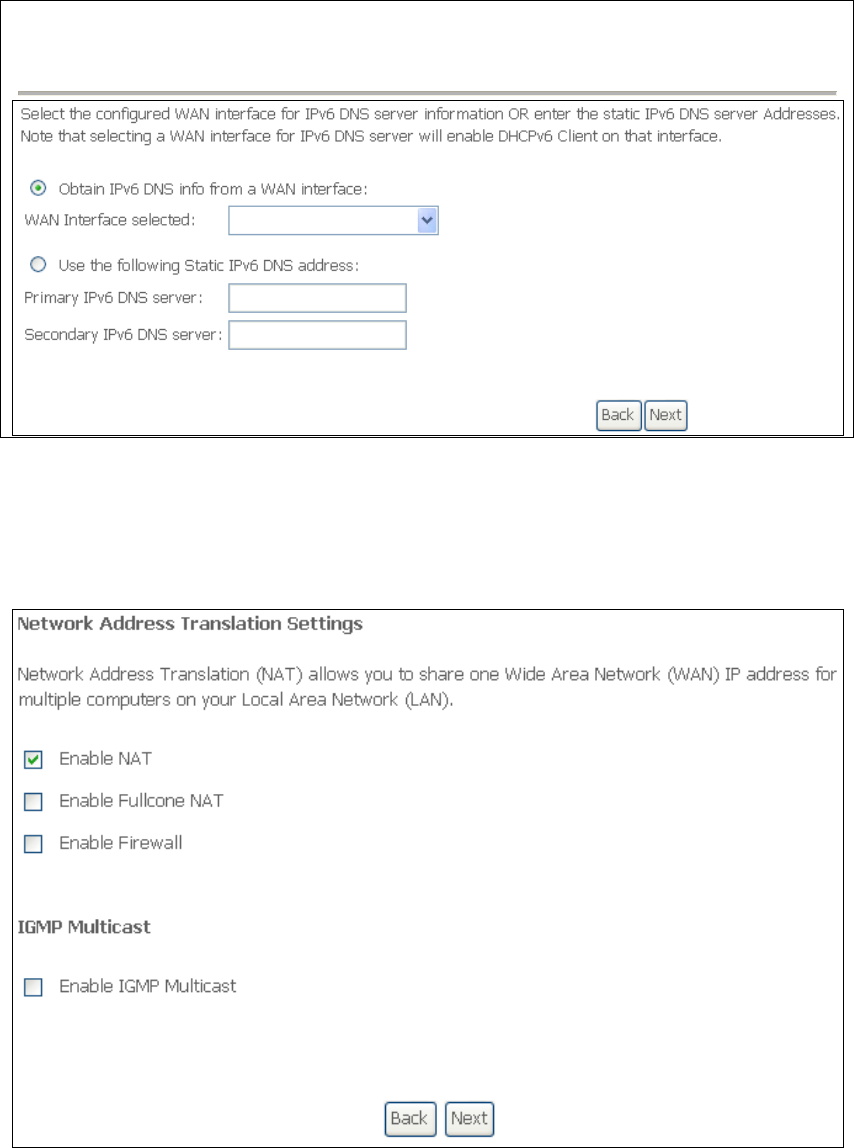
STEP 3: This screen provides access to NAT, Firewall and IGMP Multicast settings.
Enable each by selecting the appropriate checkbox . Click Next to
continue or click Back to return to the previous step.
ENABLE NAT
If the LAN is configured with a private IP address, the user should select this
checkbox . The NAT submenu will appear in the Advanced Setup menu after
reboot. On the other hand, if a private IP address is not used on the LAN side (i.e.
the LAN side is using a public IP), this checkbox should not be selected, so as to
free up system resources for improved performance.
125
ENABLE FULLCONE NAT
This option becomes available when NAT is enabled. Known as one-to-one NAT, all
requests from the same internal IP address and port are mapped to the same
external IP address and port. An external host can send a packet to the internal host,
by sending a packet to the mapped external address.
ENABLE FIREWALL
If this checkbox is selected, the Security submenu will be displayed on the
Advanced Setup menu after reboot. If firewall is not necessary, this checkbox
should not be selected so as to free up system resources for better performance.
ENABLE IGMP MULTICAST
Tick the checkbox to enable Internet Group Membership Protocol (IGMP)
multicast. IGMP is a protocol used by IPv4 hosts to report their multicast group
memberships to any neighboring multicast routers.
ENABLE MLD MULTICAST PROXY
This option displays when IPv6 is enabled. Tick the checkbox to enable Multicast
Listener Discovery (MLD). This protocol is used by IPv6 hosts to report their
multicast group memberships to any neighboring multicast routers.
STEP 4: Select WAN interfaces as system default IPv4/v6 gateways. When IPv6 is
enabled a second WAN interface selection box will appear, as shown here.
Click Next to continue or click Back to return to the previous step.
STEP 5: Select a WAN interface or enter static IP address to IPv4/v6 DNS Servers.
126
If IPv6 is enabled, an additional set of options will be shown.
Click Next to continue or click Back to return to the previous step.
STEP 6: The WAN Setup - Summary screen shows a preview of the WAN service
you have configured. Check these settings and click Apply/Save if they
are correct, or click Back to modify them.
127
After clicking Apply/Save, the new service should appear on the main screen.
To activate it you must reboot. Go to Management Reboot and click Reboot.
128
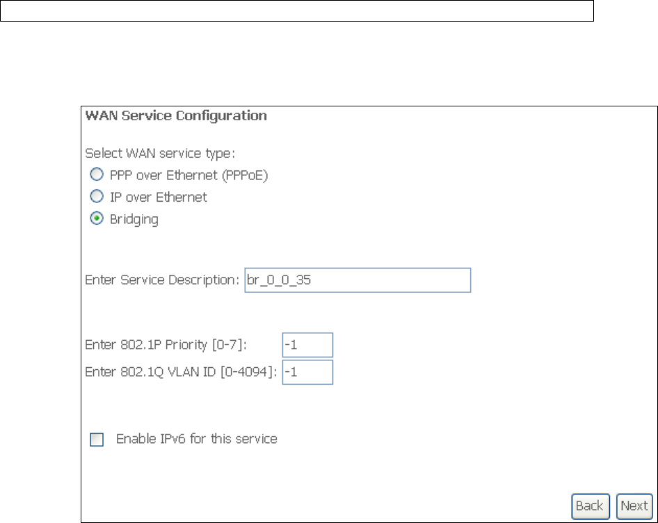
G2.3 Bridging
NOTE: This connection type is not available on the Ethernet WAN interface.
STEP 1: Select the Bridging radio button and click Next. You can also enable IPv6
by ticking the checkbox at the bottom of this screen.
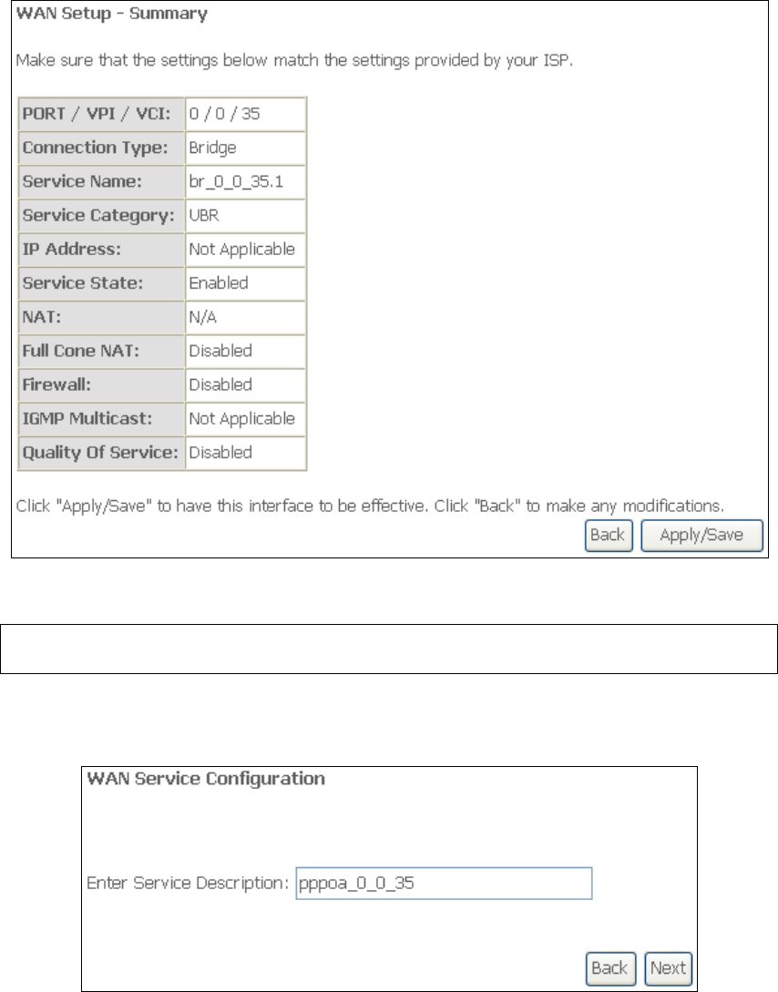
STEP 2: The WAN Setup - Summary screen shows a preview of the WAN service
you have configured. Check these settings and click Apply/Save if they
are correct, or click Back to return to the previous screen.
129
After clicking Apply/Save, the new service should appear on the main screen.
To activate it you must reboot. Go to Management Reboot and click Reboot.
NOTE: If this bridge connection is your only WAN service, the CT-5374 will be
inaccessible for remote management or technical support from the WAN.
G2.4 PPP over ATM (PPPoA)
STEP 1: Click Next to continue.
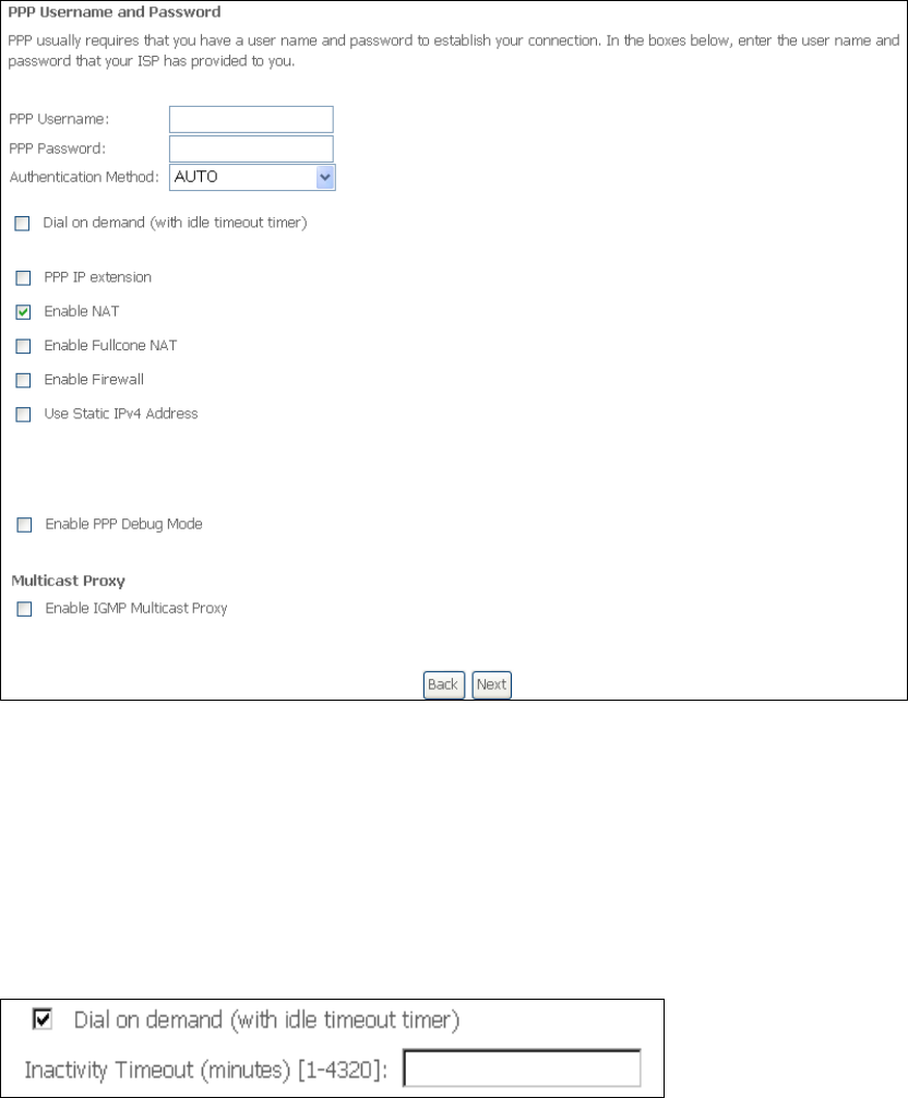
STEP 2: On the next screen, enter the PPP settings as provided by your ISP.
Click Next to continue or click Back to return to the previous step.
130
PPP SETTINGS
The PPP username and password are dependent on the requirements of the ISP.
The user name can be a maximum of 256 characters and the password a maximum
of 32 characters in length. (Authentication Method: AUTO, PAP, CHAP, or MSCHAP.)
DIAL ON DEMAND
The CT-5374 can be configured to disconnect if there is no activity for a period of
time by selecting the Dial on demand checkbox . You must also enter an
inactivity timeout period in the range of 1 to 4320 minutes.
PPP IP EXTENSION
The PPP IP Extension is a special feature deployed by some service providers.
Unless your service provider specifically requires this setup, do not select it.
PPP IP Extension does the following:
• Allows only one PC on the LAN.
• Disables NAT and Firewall.
• The device becomes the default gateway and DNS server to the PC
through DHCP using the LAN interface IP address.
• The device extends the IP subnet at the remote service provider to the
LAN PC. i.e. the PC becomes a host belonging to the same IP subnet.
• The device bridges the IP packets between WAN and LAN ports, unless
the packet is addressed to the device’s LAN IP address.
131
• The public IP address assigned by the remote side using the PPP/IPCP
protocol is actually not used on the WAN PPP interface. Instead, it is
forwarded to the PC LAN interface through DHCP. Only one PC on the
LAN can be connected to the remote, since the DHCP server within the
device has only a single IP address to assign to a LAN device.
ENABLE NAT
If the LAN is configured with a private IP address, the user should select this
checkbox . The NAT submenu will appear in the Advanced Setup menu after reboot.
On the other hand, if a private IP address is not used on the LAN side (i.e. the LAN
side is using a public IP), this checkbox should not be selected to free up system
resources for better performance.
ENABLE FULLCONE NAT
This option becomes available when NAT is enabled. Known as one-to-one NAT, all
requests from the same internal IP address and port are mapped to the same
external IP address and port. An external host can send a packet to the internal host,
by sending a packet to the mapped external address.
ENABLE FIREWALL
If this checkbox is selected, the Security submenu will be displayed on the
Advanced Setup menu after reboot. If firewall is not necessary, this checkbox
should not be selected to free up system resources for better performance.
USE STATIC IPv4 ADDRESS
Unless your service provider specially requires it, do not select this checkbox . If
selected, enter the static IP address in the IP Address field. Also, don’t forget to
adjust the IP configuration to Static IP Mode as described in 3.2 IP Configuration.
ENABLE PPP DEBUG MODE
When this option is selected, the system will put more PPP connection information
into the system log. This is for debugging errors and not for normal usage.
ENABLE IGMP MULTICAST PROXY
Tick the checkbox to enable Internet Group Membership Protocol (IGMP)
multicast. IGMP is a protocol used by IPv4 hosts to report their multicast group
memberships to any neighboring multicast routers.
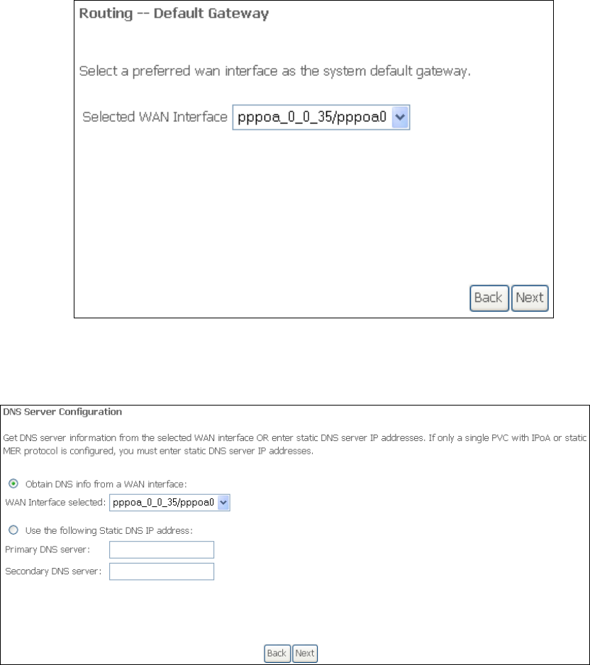
STEP 3: Select a WAN interface as the preferred default gateway route.
132
Click Next to continue or click Back to return to the previous step.
STEP 4: Select a WAN interface or enter a static IP address to the DNS Server.
Click Next to continue or click Back to return to the previous step.
133
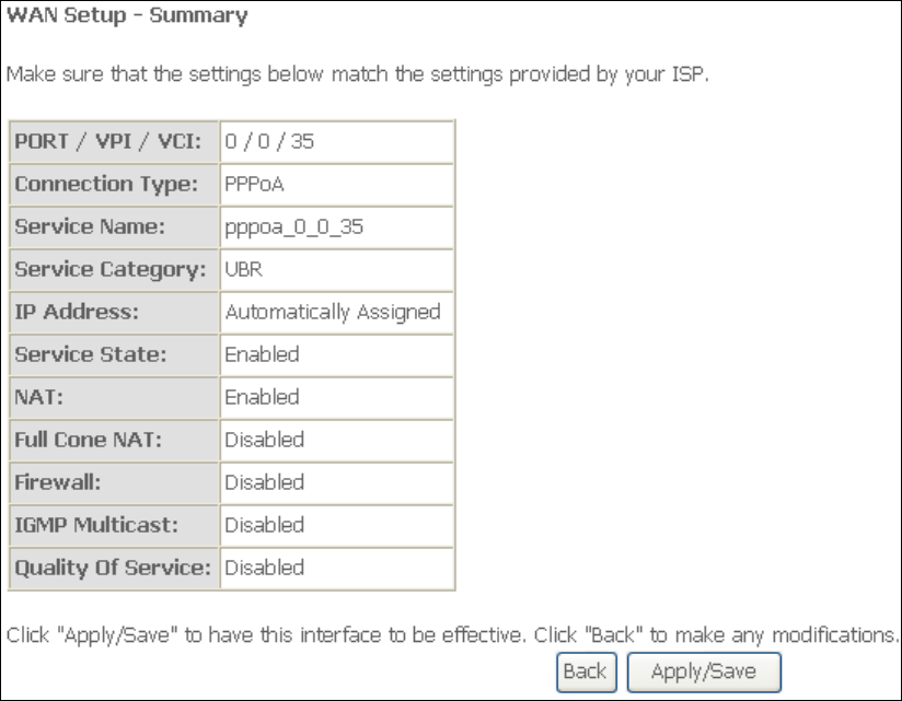
STEP 5: The WAN Setup - Summary screen shows a preview of the WAN service
you have configured. Check these settings and click Apply/Save if they
are correct, or click Back to modify them.
After clicking Apply/Save, the new service should appear on the main screen.
To activate it you must reboot. Go to Management Reboot and click Reboot.
134
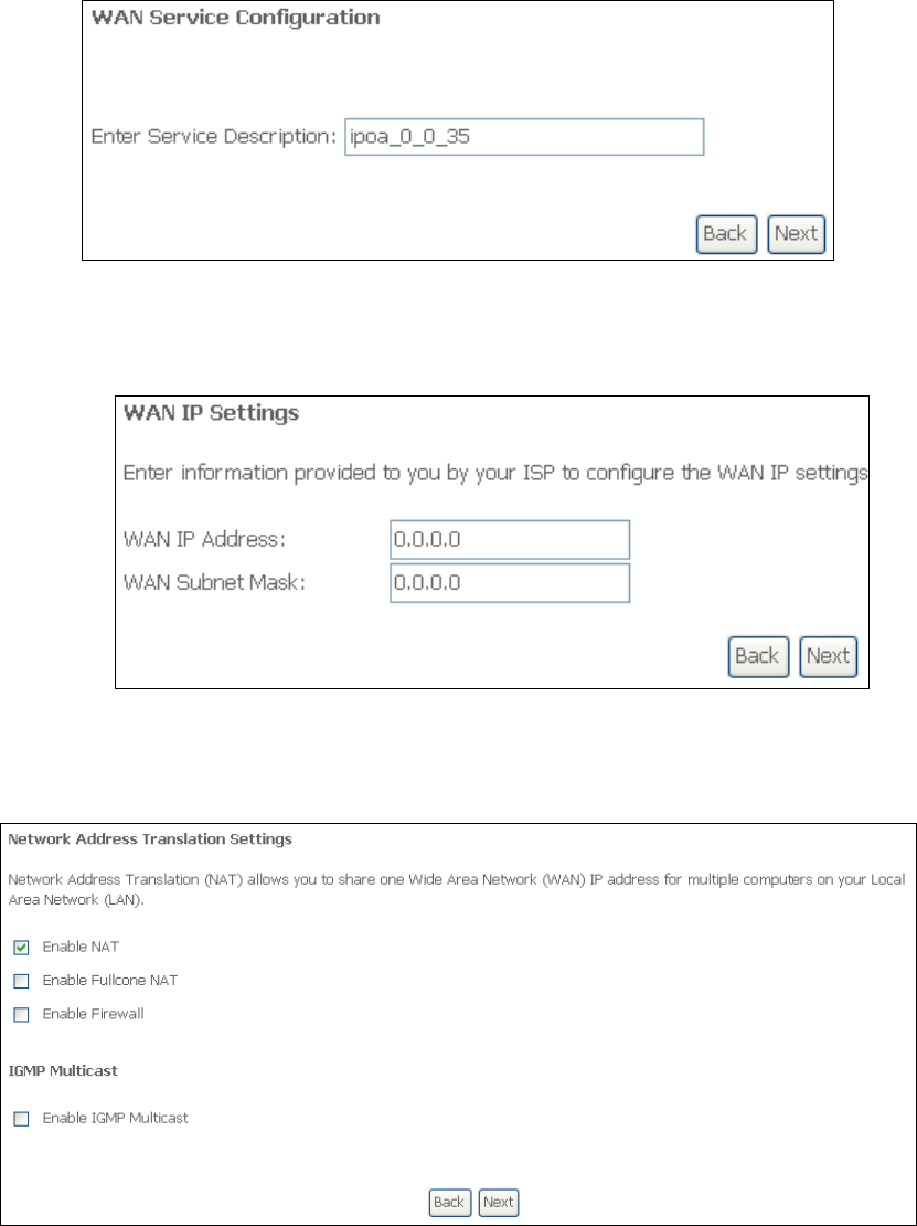
G2.5 IP over ATM (IPoA)
STEP 1: Click Next to continue.
STEP 2: Enter the WAN IP settings provided by your ISP. Click Next to continue.
STEP 3: This screen provides access to NAT, Firewall and IGMP Multicast settings.
Enable each by selecting the appropriate checkbox . Click Next to
continue or click Back to return to the previous step.
ENABLE NAT
If the LAN is configured with a private IP address, the user should select this
checkbox . The NAT submenu will appear in the Advanced Setup menu after
reboot. On the other hand, if a private IP address is not used on the LAN side (i.e.
the LAN side is using a public IP), this checkbox should not be selected, so as to
free up system resources for improved performance.
135
ENABLE FULLCONE NAT
This option becomes available when NAT is enabled. Known as one-to-one NAT, all
requests from the same internal IP address and port are mapped to the same
external IP address and port. An external host can send a packet to the internal host
by sending a packet to the mapped external address.
ENABLE FIREWALL
If this checkbox is selected, the Security submenu will be displayed on the
Advanced Setup menu after reboot. If firewall is not necessary, this checkbox
should not be selected so as to free up system resources for better performance.
ENABLE IGMP MULTICAST
Tick the checkbox to enable Internet Group Membership Protocol (IGMP)
multicast. IGMP is a protocol used by IPv4 hosts to report their multicast group
memberships to any neighboring multicast routers.
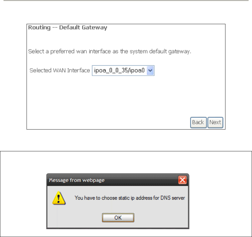
STEP 4: Select a WAN interface as the preferred default gateway route.
Click Next to continue or click Back to return to the previous step.
NOTE: If the DHCP server is not enabled on another WAN interface then the
following notification will be shown before the next screen.
STEP 5: Select a WAN interface or enter a static IP address to the DNS Server.
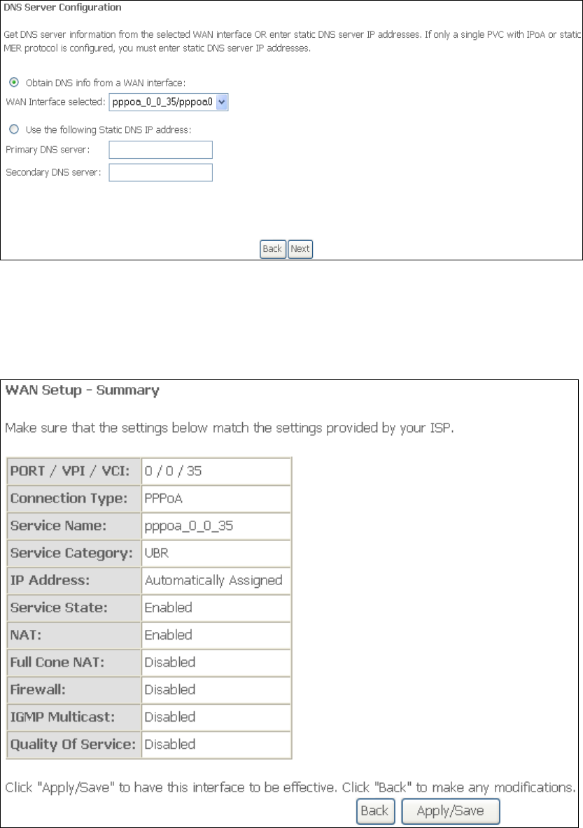
136
Click Next to continue or click Back to return to the previous step.
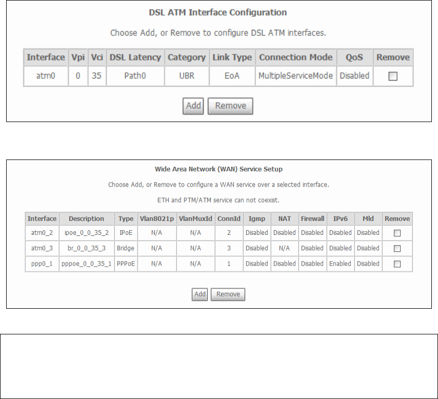
STEP 7: The WAN Setup - Summary screen shows a preview of the WAN service
you have configured. Check these settings and click Apply/Save if they
are correct, or click Back to modify them.
After clicking Apply/Save, the new service should appear on the main screen.
To activate it you must reboot. Go to Management Reboot and click Reboot.
137
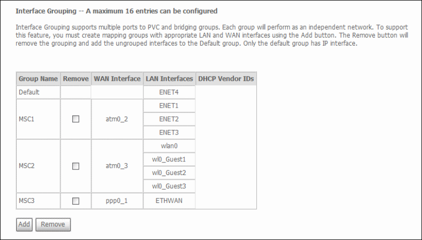
G3 ~ More About MSC Mode
The procedure for WAN connection setup in MSC mode is as follows:
STEP 1: Create a Layer2 interface in MSC connection mode.
STEP 2: Add WAN connections to the interface (Bridge, PPPoE or IPoE).
STEP 3: Use 5.14 Interface Grouping to connect LAN and WAN interfaces.
These three steps are repeated below with screenshots added for reference.
STEP 1: Create a Layer2 interface in MSC connection mode.
STEP 2: Add WAN connections to the interface (Bridge, PPPoE or IPoE).
NOTES: If QoS is configured on the first MSC connection, it will be configured by
default for all subsequent connections.
If a MSC connection is removed every other MSC connection should be
removed to avoid potential configuration problems.
138
STEP 3: Use 5.14 Interface Grouping to connect LAN and WAN interfaces.
See the instructions in 5.14 Interface Grouping for help with this final step.