Comtrend 5374 Multi DSL Wireless Router User Manual UM CT 5374 A2 0
Comtrend Corporation Multi DSL Wireless Router UM CT 5374 A2 0
Comtrend >
Contents
- 1. Users Manual 1 of 3
- 2. User manual 2 of 3
- 3. User manual 3 of 3
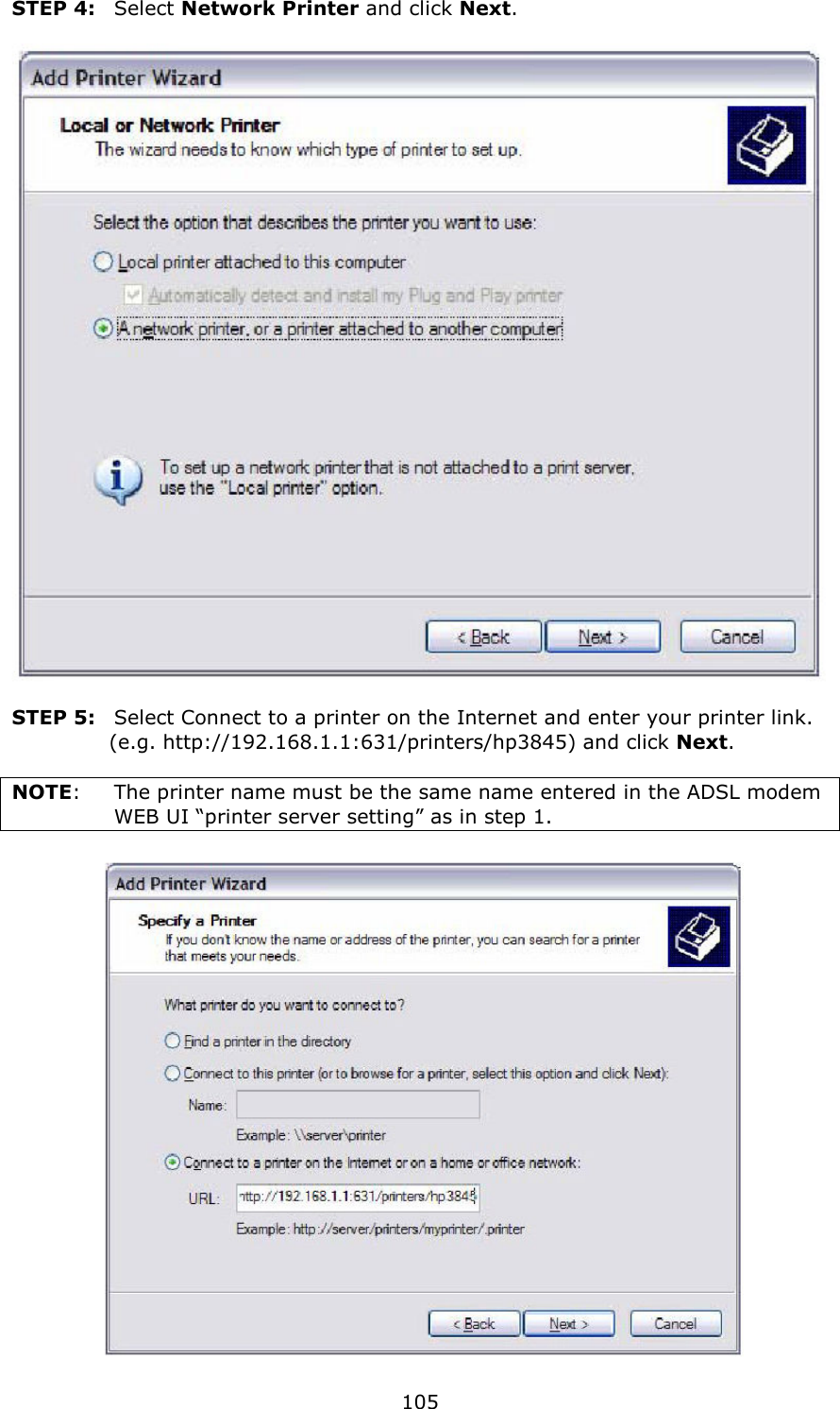
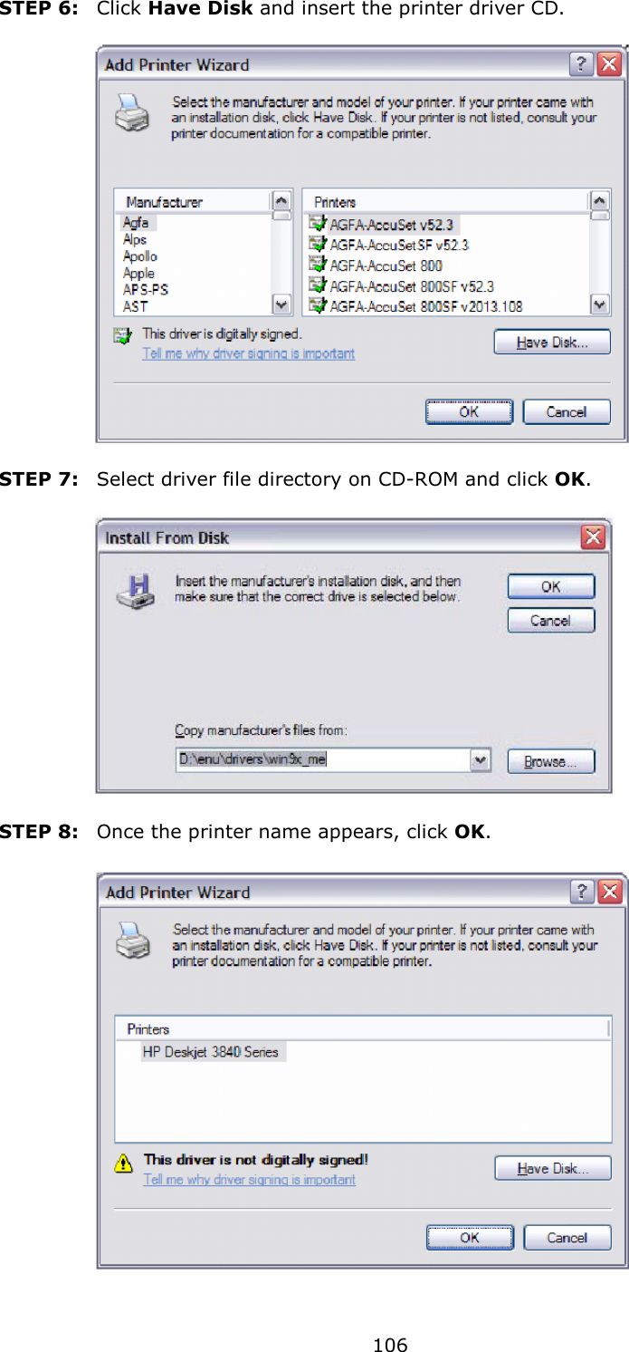
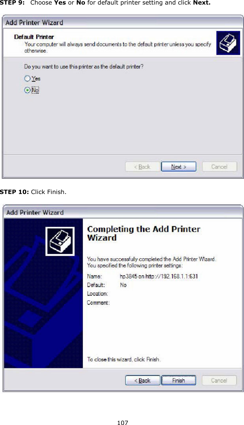
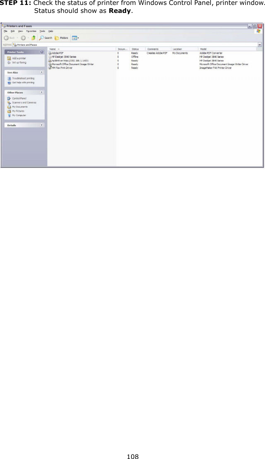
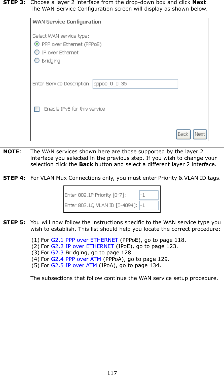
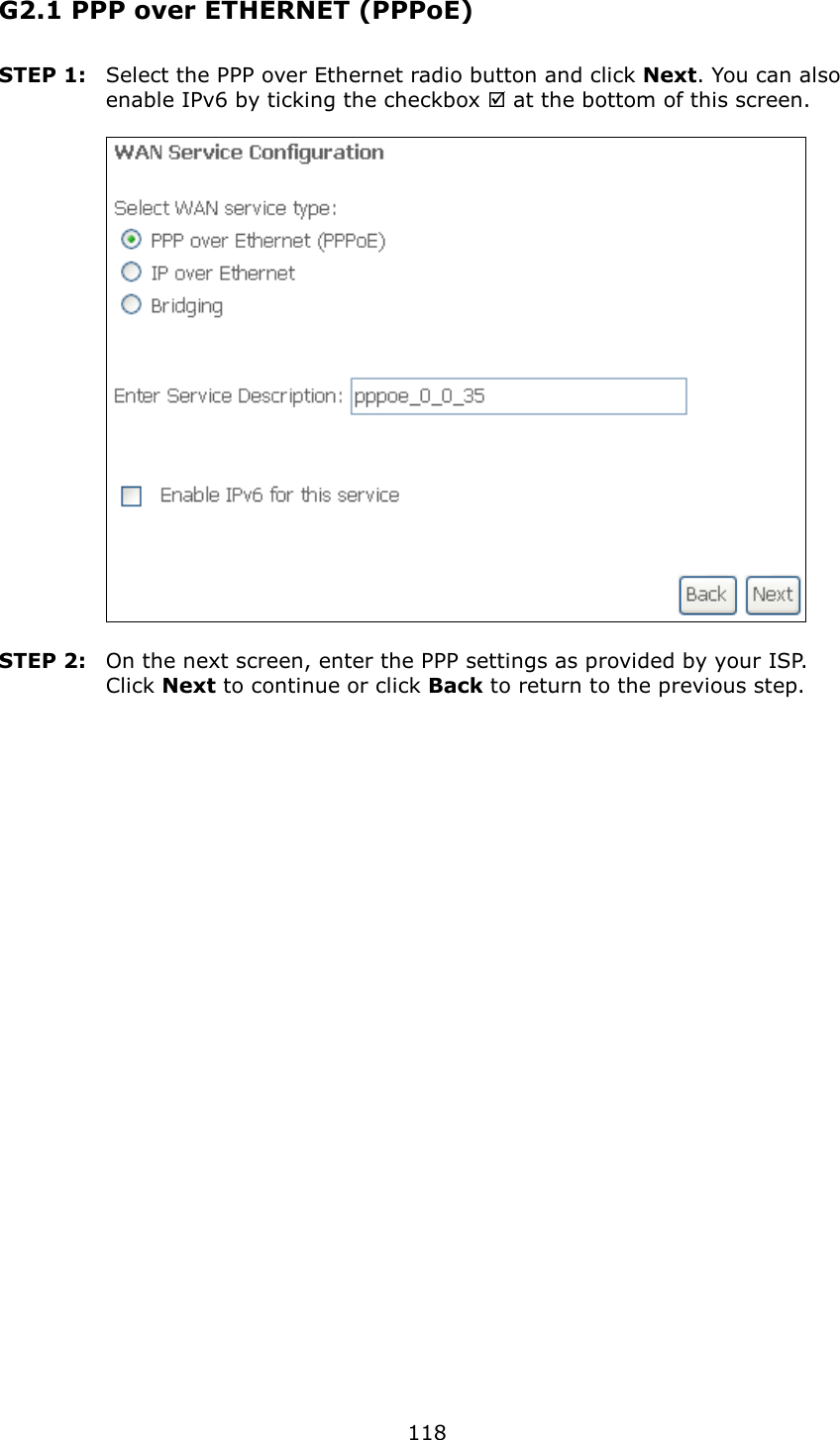
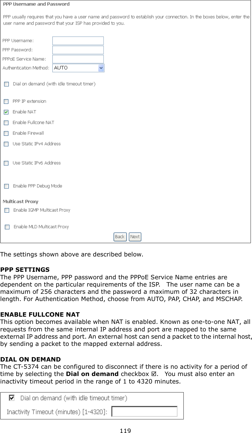
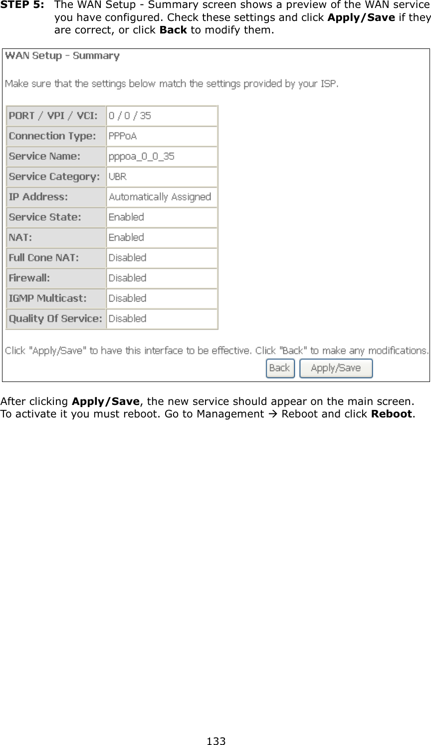
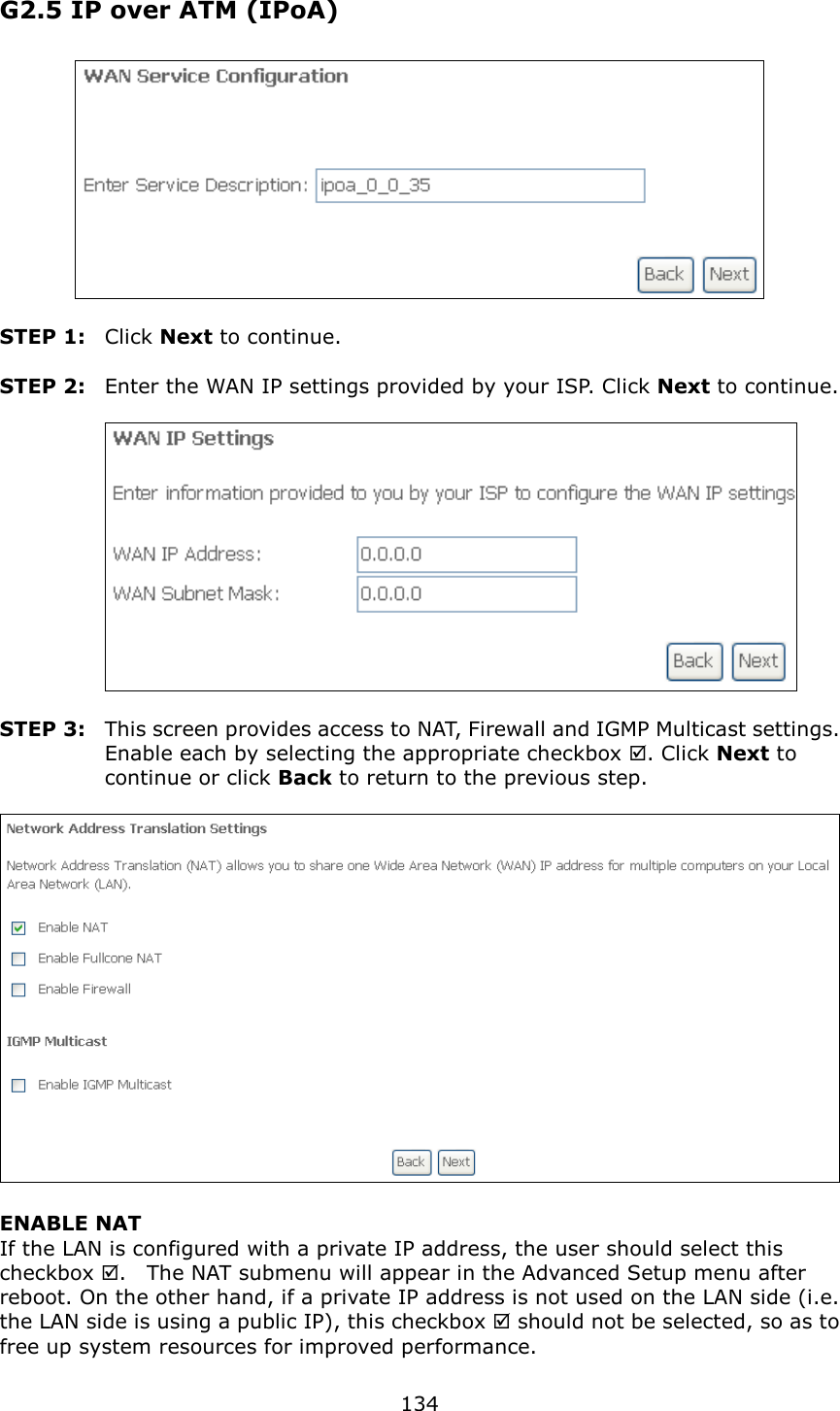
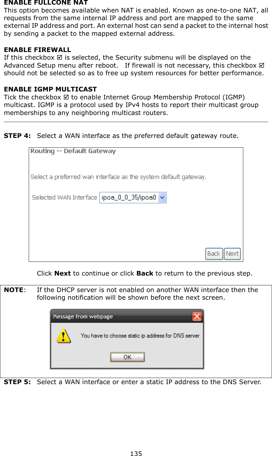
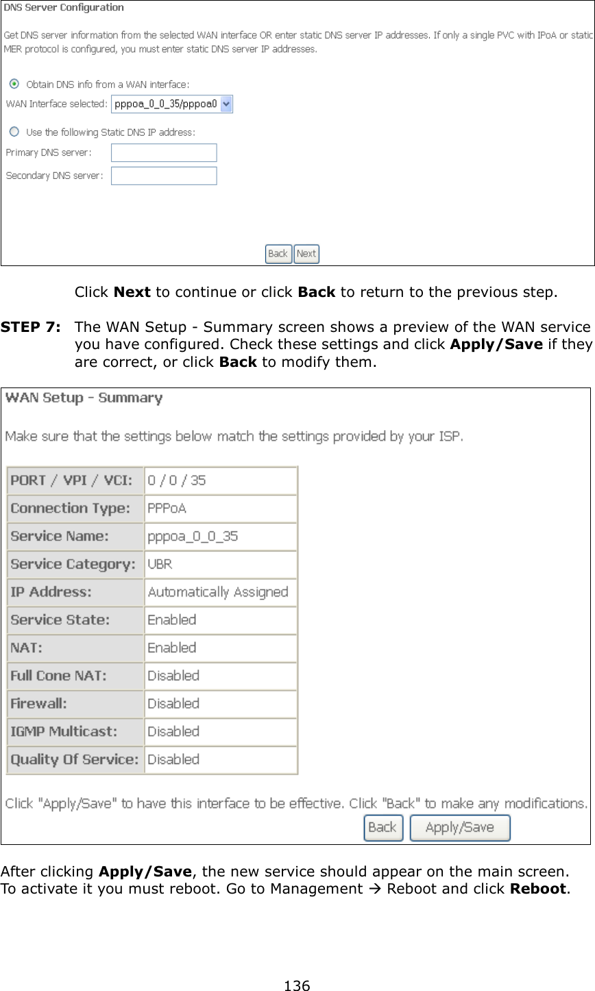
User manual 3 of 3