Comtrend 5374 Multi DSL Wireless Router User Manual UM CT 5374 A2 0
Comtrend Corporation Multi DSL Wireless Router UM CT 5374 A2 0
Comtrend >
Contents
- 1. Users Manual 1 of 3
- 2. User manual 2 of 3
- 3. User manual 3 of 3
Users Manual 1 of 3


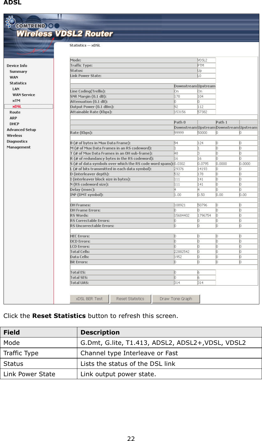
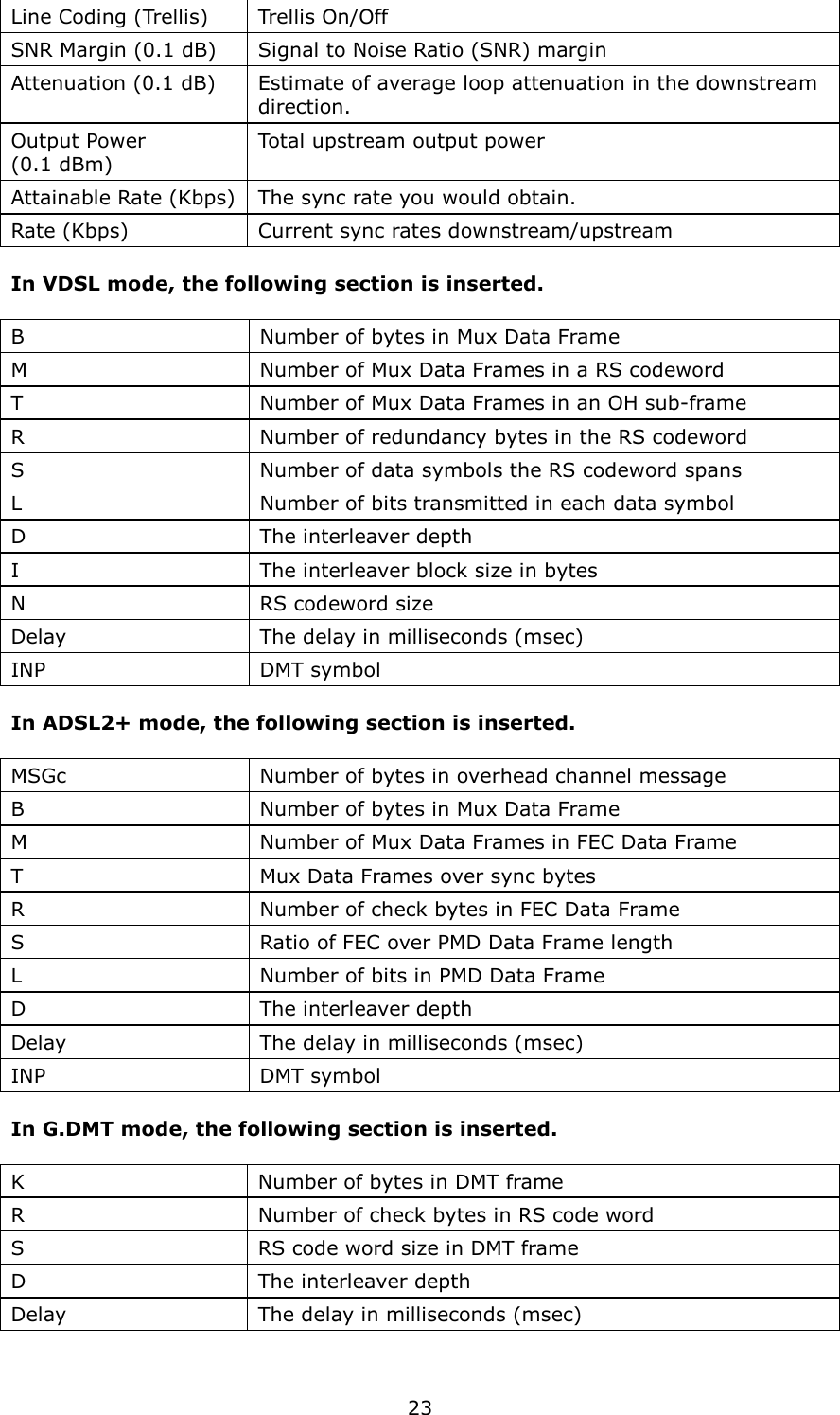
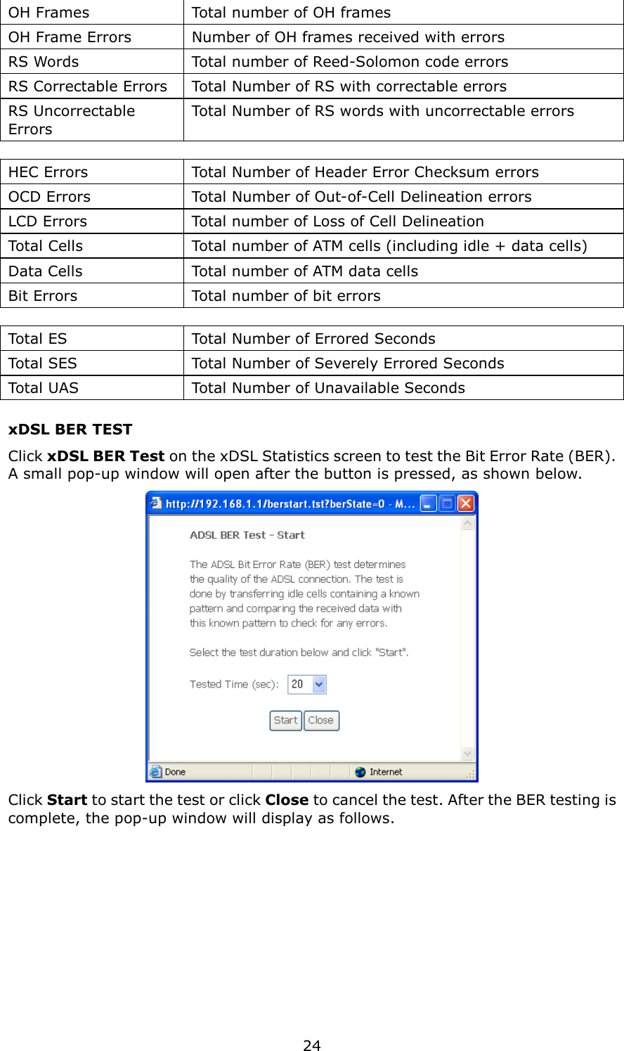
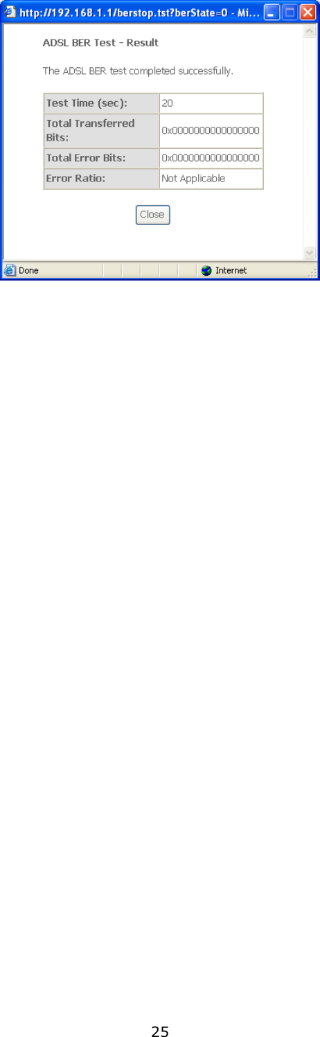
![49 Field Description Source MAC Address A packet belongs to SET-1, if a binary-AND of its source MAC address with the Source MAC Mask is equal to the binary-AND of the Source MAC Mask and this field. Source MAC Mask This is the mask used to decide how many bits are checked in Source MAC Address. Destination MAC Address A packet belongs to SET-1 then the result that the Destination MAC Address of its header binary-AND to the Destination MAC Mask must equal to the result that this field binary-AND to the Destination MAC Mask. Destination MAC Mask This is the mask used to decide how many bits are checked in Destination MAC Address. Classification Results Assign Classification Queue The queue configurations are presented in this format: “Interfacename&Prece P&Queue Q” where P and Q are the Precedence and Queue Key values for the corresponding Interface as listed on the Queue Config screen. Mark Differentiated Service Code Point The selected Code Point gives the corresponding priority to packets that satisfy the rule. Mark 802.1p Priority Select between 0-7. Lower values have higher priority. Tag VLAN ID Enter a 802.1Q VLAN ID tag [2-4094] Set Rate Control The data transmission rate limit in kbps. 5.9 Routing This following routing functions are accessed from this menu: Default Gateway, Static Route, Policy Routing, RIP and IPv6 Static Route. NOTE: In bridge mode, the RIP menu option is hidden while the other menu options are shown but ineffective.](https://usermanual.wiki/Comtrend/5374.Users-Manual-1-of-3/User-Guide-1280064-Page-50.png)