Comtrend VR3060U Wireless Gateway User Manual UM VR3060 addingEMC 160909
Comtrend Corporation Wireless Gateway UM VR3060 addingEMC 160909
UserManual.wiki
>
Comtrend
>
VR3060U User Manual
>
User Manual-1
Contents
1.
User Manual-1
2.
User Manual-2
User Manual-1
Navigation menu
Upload a User Manual
Namespaces
Wiki Guide
HTML
PDF
Info
Views
User Manual
Discussion / Help
Navigation

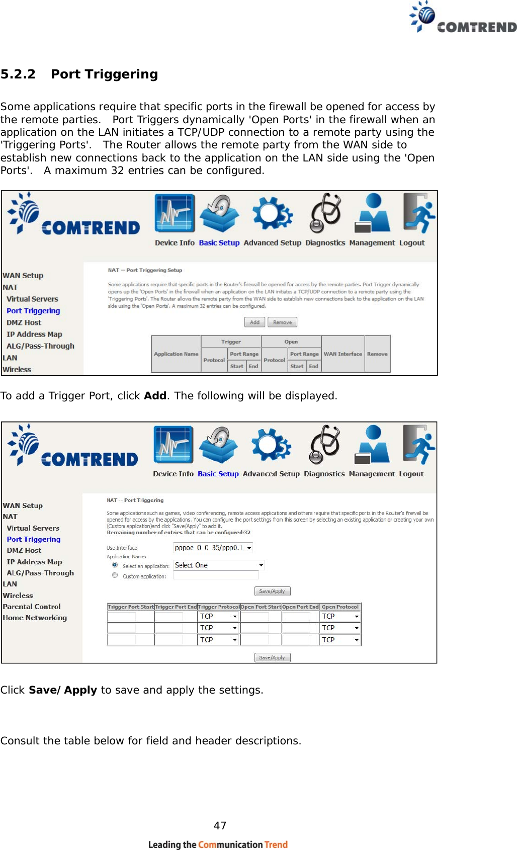
![61 Option Description Hide Access Point Select Hide Access Point to protect the access point from detection by wireless active scans. If the access point is hidden, it will not be listed or listed with empty SSID in the scan result of wireless stations. To connect a client to a hidden access point, the station must add the access point manually to its wireless configuration. Clients Isolation When enabled, it prevents client PCs from seeing one another in My Network Places or Network Neighborhood. Also, prevents one wireless client communicating with another wireless client. Disable WMM Advertise Stops the router from ‘advertising’ its Wireless Multimedia (WMM) functionality, which provides basic quality of service for time-sensitive applications (e.g. VoIP, Video). Enable Wireless Multicast Forwarding Select the checkbox to enable this function. SSID [1-32 characters] Sets the wireless network name. SSID stands for Service Set Identifier. All stations must be configured with the correct SSID to access the WLAN. If the SSID does not match, that user will not be granted access. BSSID The BSSID is a 48-bit identity used to identify a particular BSS (Basic Service Set) within an area. In Infrastructure BSS networks, the BSSID is the MAC (Media Access Control) address of the AP (Access Point); and in Independent BSS or ad hoc networks, the BSSID is generated randomly. Country A drop-down menu that permits worldwide and specific national settings. Local regulations limit channel range: US= worldwide, Japan=1-14, Jordan= 10-13, Israel= 1-13 Country RegRev Wireless country code for transmit power limit. Max Clients The maximum number of clients that can access the router. Wireless - Guest / Virtual Access Points This router supports multiple SSIDs called Guest SSIDs or Virtual Access Points. To enable one or more Guest SSIDs select the checkboxes in the Enabled column. To hide a Guest SSID, select its checkbox in the Hidden column. Do the same for Isolate Clients and Disable WMM Advertise. For a description of these two functions, see the previous entries for “Clients Isolation” and “Disable WMM Advertise”. Similarly, for Enable WMF, Max Clients and BSSID, consult the matching entries in this table. NOTE: Remote wireless hosts cannot scan Guest SSIDs.](https://usermanual.wiki/Comtrend/VR3060U.User-Manual-1/User-Guide-3152919-Page-62.png)
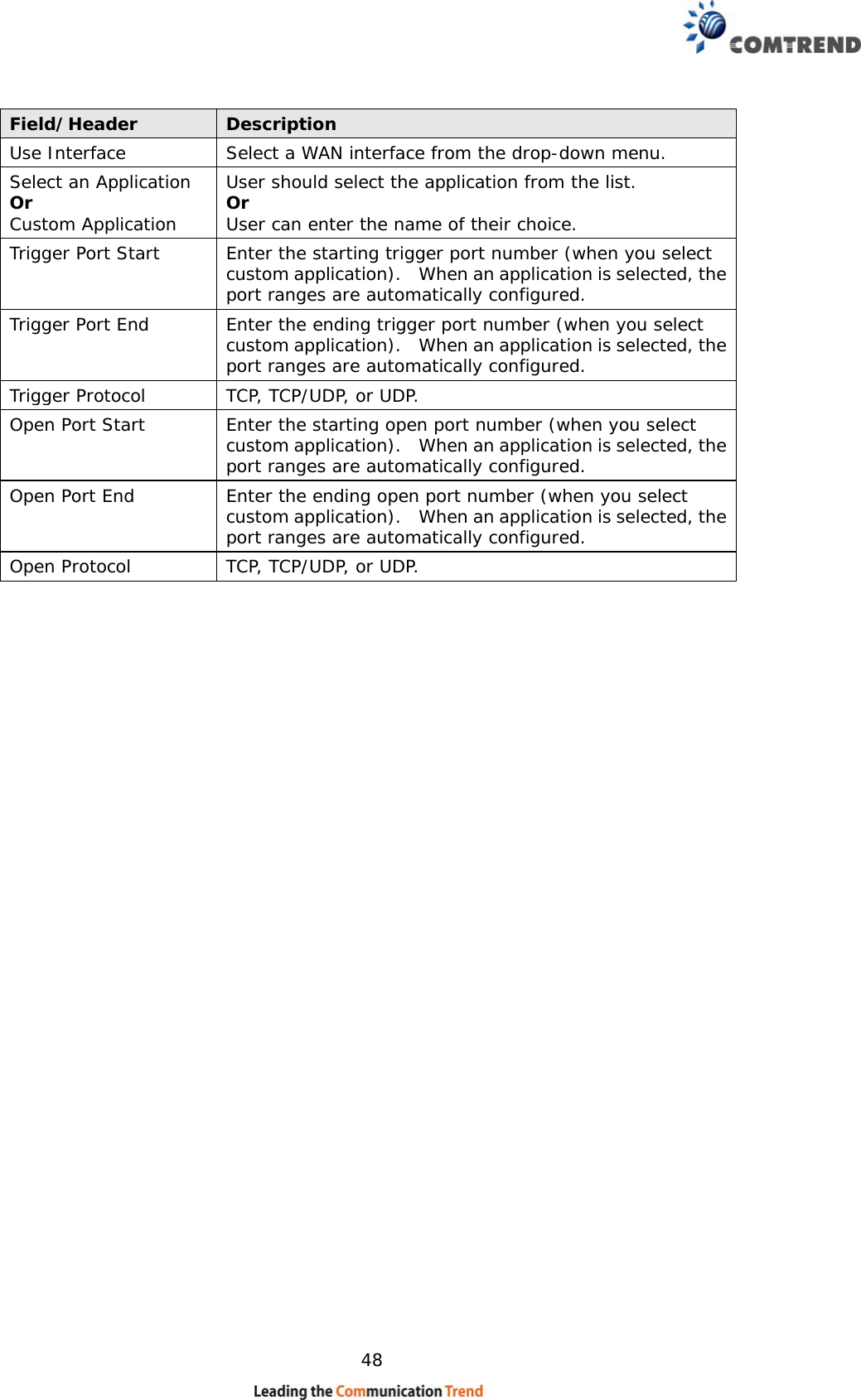
![66 Option Description Hide Access Point Select Hide Access Point to protect the access point from detection by wireless active scans. If the access point is hidden, it will not be listed or listed with empty SSID in the scan result of wireless stations. To connect a client to a hidden access point, the station must add the access point manually to its wireless configuration. Clients Isolation When enabled, it prevents client PCs from seeing one another in My Network Places or Network Neighborhood. Also, prevents one wireless client communicating with another wireless client. Disable WMM Advertise Stops the router from ‘advertising’ its Wireless Multimedia (WMM) functionality, which provides basic quality of service for time-sensitive applications (e.g. VoIP, Video). Enable Wireless Multicast Forwarding Select the checkbox to enable this function. SSID [1-32 characters] Sets the wireless network name. SSID stands for Service Set Identifier. All stations must be configured with the correct SSID to access the WLAN. If the SSID does not match, that user will not be granted access. BSSID The BSSID is a 48-bit identity used to identify a particular BSS (Basic Service Set) within an area. In Infrastructure BSS networks, the BSSID is the MAC (Media Access Control) address of the AP (Access Point); and in Independent BSS or ad hoc networks, the BSSID is generated randomly. Country A drop-down menu that permits worldwide and specific national settings. Local regulations limit channel range: US= worldwide, Japan=1-14, Jordan= 10-13, Israel= 1-13 Country RegRev Wireless country code for transmit power limit. Max Clients The maximum number of clients that can access the router. Wireless - Guest / Virtual Access Points This router supports multiple SSIDs called Guest SSIDs or Virtual Access Points. To enable one or more Guest SSIDs select the checkboxes in the Enabled column. To hide a Guest SSID, select its checkbox in the Hidden column. Do the same for Isolate Clients and Disable WMM Advertise. For a description of these two functions, see the previous entries for “Clients Isolation” and “Disable WMM Advertise”. Similarly, for Enable WMF, Max Clients and BSSID, consult the matching entries in this table. NOTE: Remote wireless hosts cannot scan Guest SSIDs.](https://usermanual.wiki/Comtrend/VR3060U.User-Manual-1/User-Guide-3152919-Page-67.png)
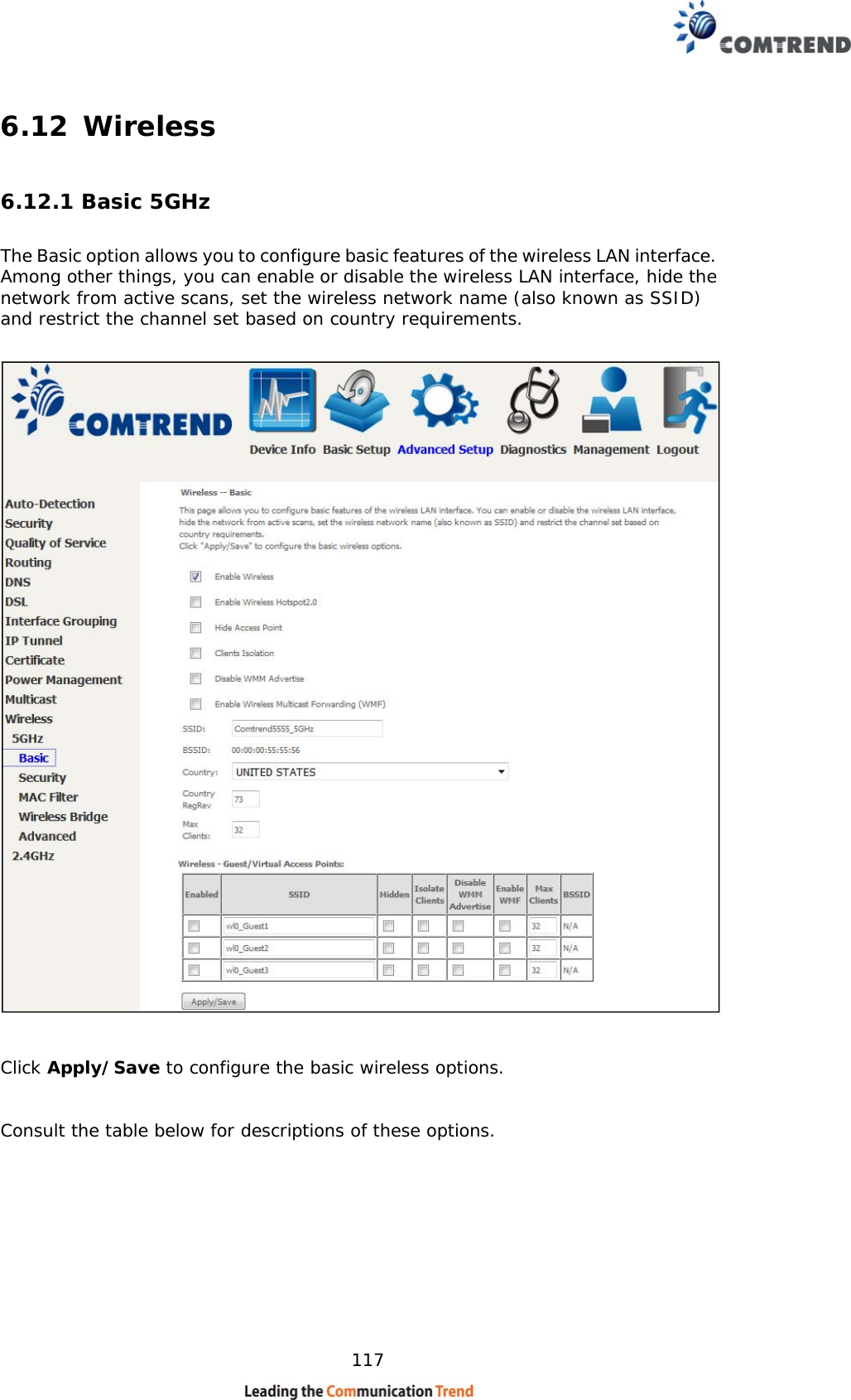
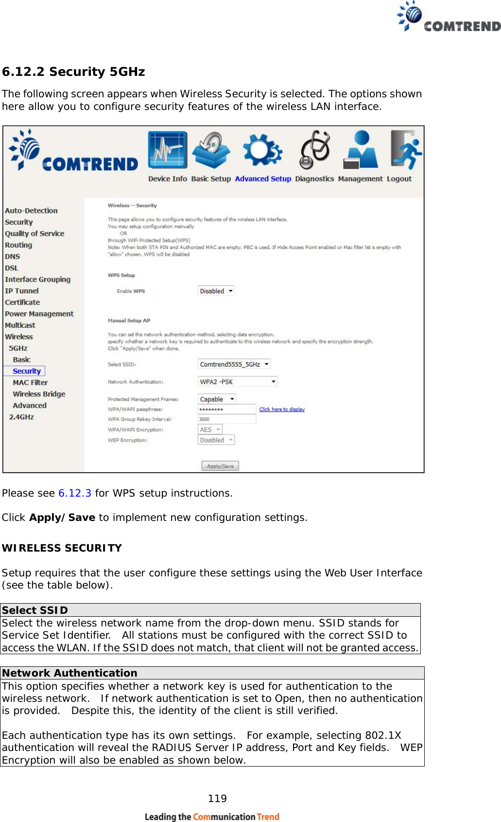
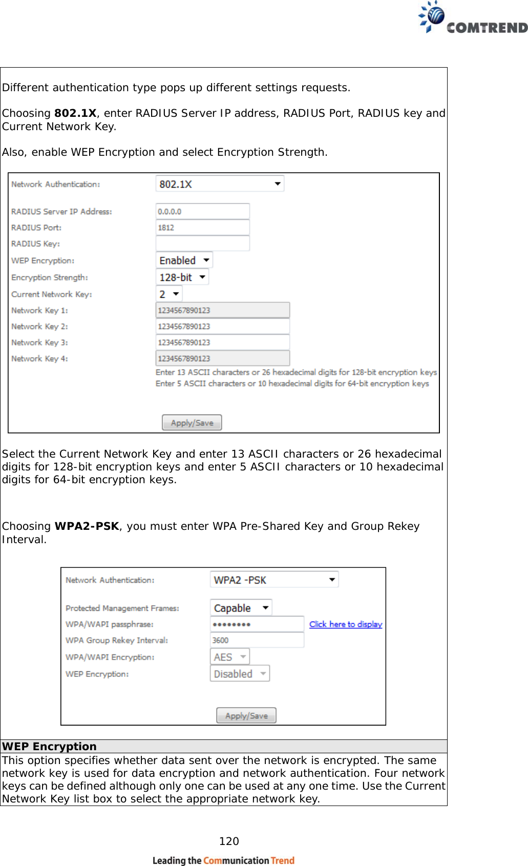
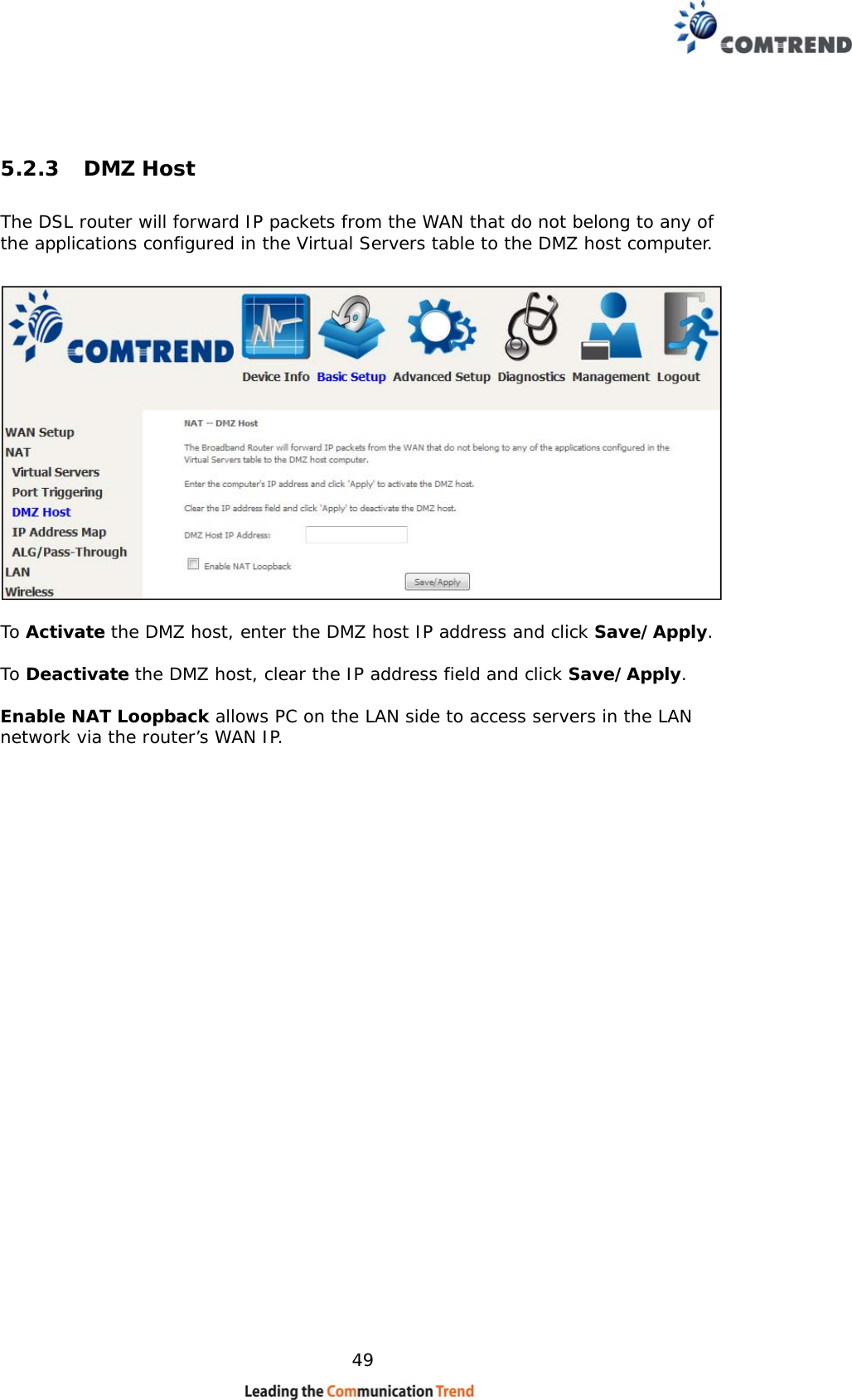
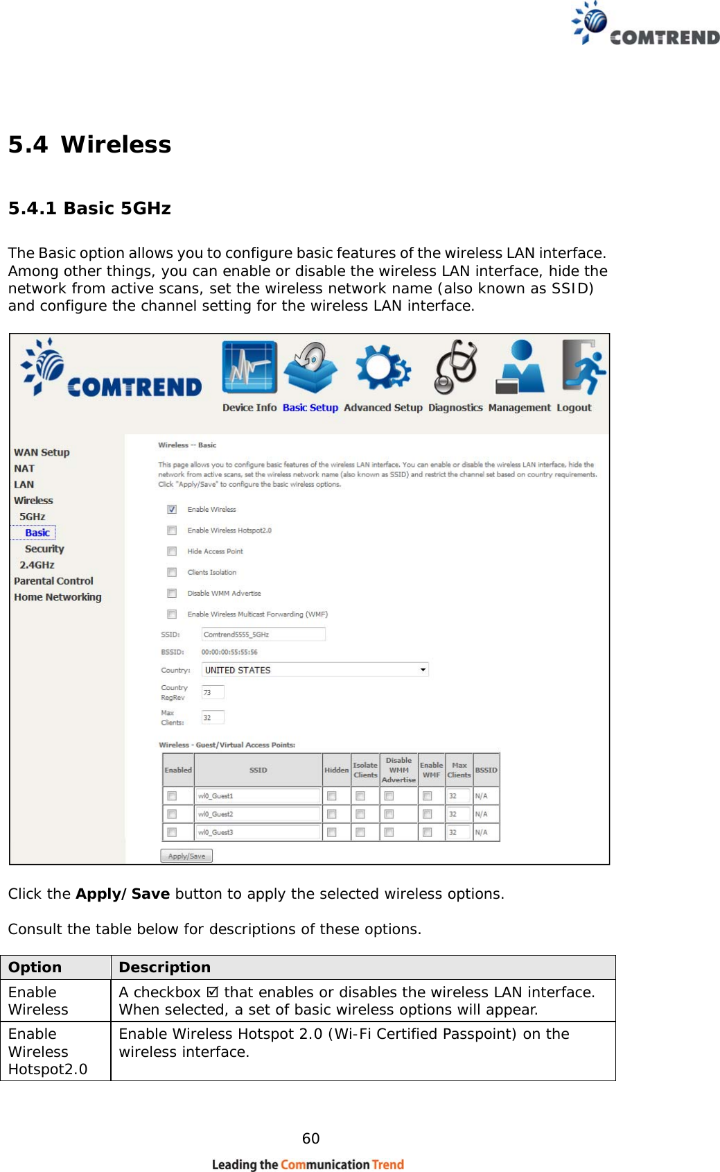
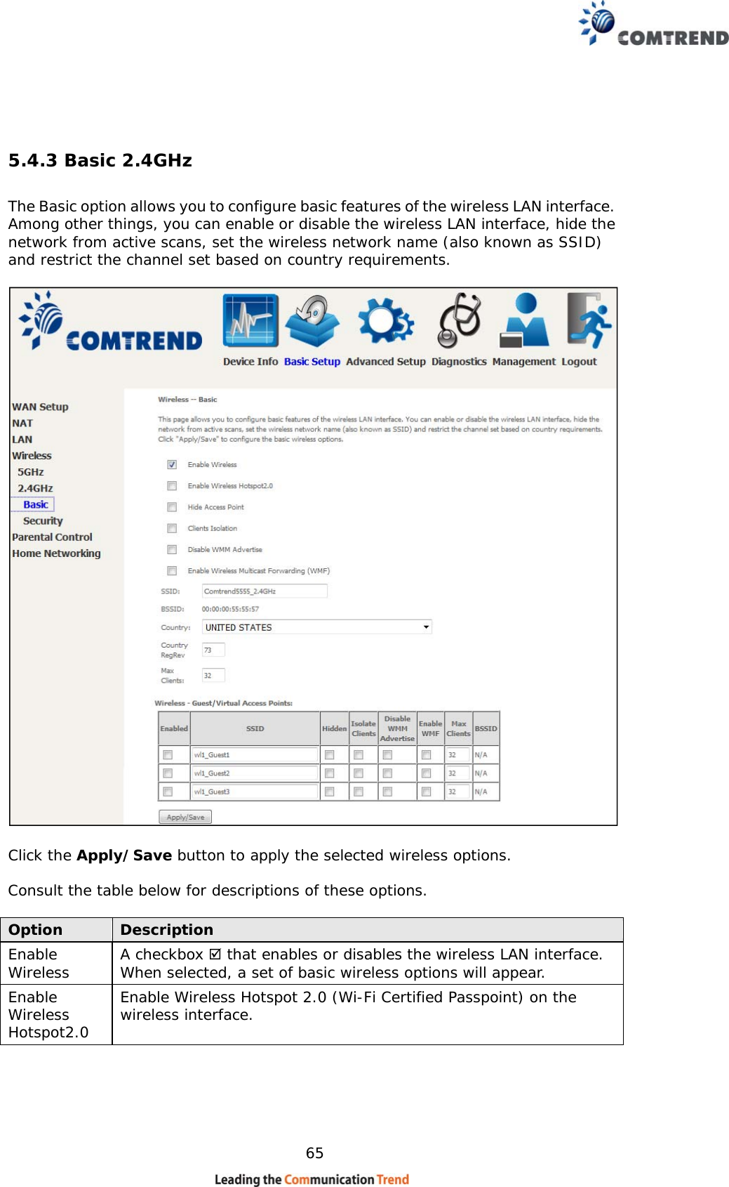
![118 Option Description Enable Wireless A checkbox that enables or disables the wireless LAN interface. When selected, a set of basic wireless options will appear. Enable Wireless Hotspot2.0 Enable Wireless Hotspot 2.0 (Wi-Fi Certified Passpoint) on the wireless interface. Hide Access Point Select Hide Access Point to protect the access point from detection by wireless active scans. If the access point is hidden, it will not be listed or listed with empty SSID in the scan result of wireless stations. To connect a client to a hidden access point, the station must add the access point manually to its wireless configuration. Clients Isolation When enabled, it prevents client PCs from seeing one another in My Network Places or Network Neighborhood. Also, prevents one wireless client communicating with another wireless client. Disable WMM Advertise Stops the router from ‘advertising’ its Wireless Multimedia (WMM) functionality, which provides basic quality of service for time-sensitive applications (e.g. VoIP, Video). Enable Wireless Multicast Forwarding Select the checkbox to enable this function. SSID [1-32 characters] Sets the wireless network name. SSID stands for Service Set Identifier. All stations must be configured with the correct SSID to access the WLAN. If the SSID does not match, that user will not be granted access. BSSID The BSSID is a 48-bit identity used to identify a particular BSS (Basic Service Set) within an area. In Infrastructure BSS networks, the BSSID is the MAC (Media Access Control) address of the AP (Access Point); and in Independent BSS or ad hoc networks, the BSSID is generated randomly. Country A drop-down menu that permits worldwide and specific national settings. Local regulations limit channel range: US= worldwide, Japan=1-14, Jordan= 10-13, Israel= 1-13 Country RegRev Wireless country code for transmit power limit. Max Clients The maximum number of clients that can access the router. Wireless - Guest / Virtual Access Points This router supports multiple SSIDs called Guest SSIDs or Virtual Access Points. To enable one or more Guest SSIDs select the checkboxes in the Enabled column. To hide a Guest SSID select its checkbox in the Hidden column. Do the same for Isolate Clients and Disable WMM Advertise. For a description of these two functions, see the previous entries for “Clients Isolation” and “Disable WMM Advertise”. Similarly, for Enable WMF, Max Clients and BSSID, consult the matching entries in this table. NOTE: Remote wireless hosts cannot scan Guest SSIDs.](https://usermanual.wiki/Comtrend/VR3060U.User-Manual-1/User-Guide-3152919-Page-119.png)