Comtrend VR3060U Wireless Gateway User Manual UM VR3060 addingEMC 160909
Comtrend Corporation Wireless Gateway UM VR3060 addingEMC 160909
Comtrend >
Contents
- 1. User Manual-1
- 2. User Manual-2
User Manual-1
261099-038
VR-3060u, VR-3060
Wireless Gateway
User Manual
Version A1.0, December 22, 2015

1
Preface
This manual provides information related to the installation and operation of this
device. The individual reading this manual is presumed to have a basic
understanding of telecommunications terminology and concepts.
If you find the product to be inoperable or malfunctioning, please contact technical
support for immediate service by email at INT-support@comtrend.com
For product update, new product release, manual revision, or software upgrades,
please visit our website at http://www.comtrend.com
Important Safety Instructions
With reference to unpacking, installation, use, and maintenance of your electronic
device, the following basic guidelines are recommended:
• Do not use or install this product near water, to avoid fire or shock hazard. For
example, near a bathtub, kitchen sink or laundry tub, or near a swimming pool.
Also, do not expose the equipment to rain or damp areas (e.g. a wet basement).
• Do not connect the power supply cord on elevated surfaces. Allow it to lie freely.
There should be no obstructions in its path and no heavy items should be placed
on the cord. In addition, do not walk on, step on, or mistreat the cord.
• Use only the power cord and adapter that are shipped with this device.
• To safeguard the equipment against overheating, make sure that all openings in
the unit that offer exposure to air are not blocked.
• Avoid using a telephone (other than a cordless type) during an electrical storm.
There may be a remote risk of electric shock from lightening. Also, do not use
the telephone to report a gas leak in the vicinity of the leak.
• Never install telephone wiring during stormy weather conditions.
CAUTION:
To reduce the risk of fire, use only No. 26 AWG or larger
telecommunication line cord.
Always disconnect all telephone lines from the wall outlet before servicing
or disassembling this equipment.
WARNING
Disconnect the power line from the device before servicing.
Power supply specifications are clearly stated in Appendix C -
Specifications.

2
FCC & ISED
User Information
Any changes or modifications not expressly approved by the party responsible for
compliance could void your authority to operate the equipment.
Aucune modification apportée à l’appareil par l’utilisateur, quelle qu’en soit la
nature. Tout changement ou modification peuvent annuler le droit d’utilisation de
l’appareil par l’utilisateur.
Note: This equipment has been tested and found to comply with the limits for a
Class B digital device, pursuant to part 15 of the FCC Rules. These limits are
designed to provide reasonable protection against harmful interference in a
residential installation. This equipment generates, uses and can radiate radio
frequency energy and, if not installed and used in accordance with the instructions,
may cause harmful interference to radio communications. However, there is no
guarantee that interference will not occur in a particular installation. If this
equipment does cause harmful interference to radio or television reception, which
can be determined by turning the equipment off and on, the user is encouraged to
try to correct the interference by one or more of the following measures:
—Reorient or relocate the receiving antenna.
—Increase the separation between the equipment and receiver.
—Connect the equipment into an outlet on a circuit different from that to which the
receiver is connected.
—Consult the dealer or an experienced radio/TV technician for help.
This Class B digital apparatus complies with Canadian ICES-003.
To reduce potential radio interference to other users, the antenna type and
its gain should be so chosen that the equivalent isotropically radiated power
(e.i.r.p.) is not more than that permitted for successful communication.
This device complies with Industry Canada licence-exempt RSS standard(s).
Operation is subject to the following two conditions:
1. This device may not cause interference, and
2. This device must accept any interference, including interference that may
cause undesired operation of the device.
Cet appareil numérique de la classe B est conforme à la norme NMB-003
Canada.
Pour réduire le risque d’interférence aux autres utilisateurs, le type d’antenne
et son gain doivent être choisies de façon que la puissance isotrope
rayonnée équivalente (PIRE) ne dépasse pas ce qui est nécessaire pour une
communication réussie.
Cet appareil est conforme à la norme RSS Industrie Canada exempts de licence
norme(s). Son fonctionnement est soumis aux deux conditions suivantes:
1. Cet appareil ne peut pas provoquer d’interférences et
2. Cet appareil doit accepter toute interférence, y compris les interférences
qui peuvent causer un mauvais fonctionnement du dispositif.

3
Radiation Exposure
FCC ID: L9VVR3060U
IC: 4013A-VR3060U
US: 5SYDL01ANL3240U
REN: 0.1A
FCC
1. This Transmitter must not be colocated or operating in conjunction with any
other antenna or transmitter.
2. This equipment complies with FCC RF radiation exposure limits set forth for an
uncontrolled environment. This
equipment should be installed and operated with a minimum distance of 20
centimeters between the radiator and your
body.
ISED
This device complies with the ISED radiation exposure limit set forth for an
uncontrolled environment. This device should be installed and operated with
minimum distance 20cm between the radiator & your body. This transmitter must
not be co-located or operating in conjunction with any other antenna or
transmitter.
Cet équipement est conforme avec l'exposition aux radiations ISED définies pour
un environnement non contrôlé. Cet équipement doit être installé et utilisé à une
distance minimum de 20 cm entre le radiateur et votre corps. Cet émetteur ne doit
pas être co-localisées ou opérant en conjonction avec une autre antenne ou
transmetteur.
Operations in the 5.15-5.25Ghz band are restricted to indoor usage only.
Le fonctionnement sur la bande 5,15–5,25Ghz est limité à une utilisation
intérieure uniquement.
This radio transmitter (identify the device by certification number) has been
approved by Industry Canada to operate with the antenna types listed below with
the maximum permissible gain indicated. Antenna types not included in this list,
having a gain greater than the maximum gain indicated for that type, are strictly
prohibited for use with this device.
Model Name: AN2450-64D02BBO
Type: External
Gain:
2.4G: 2.5 dBi
5G: 2.5 dBi
Model Name: AN2450-64D03BBO
Type: External
Gain:
4
2.4G: 1.2 dBi
5G: 2.5 dBi
The REN statement is the following:
"The Ringer Equivalence Number (REN) indicates the maximum number of devices
allowed to be connected to a telephone interface. The termination of an interface
may consist of any combination of devices subject only to the requirement that the
sum of the RENs of all the devices not exceed five."
Copyright
Copyright©2015 Comtrend Corporation. All rights reserved. The information
contained herein is proprietary to Comtrend Corporation. No part of this document
may be translated, transcribed, reproduced, in any form, or by any means without
prior written consent of Comtrend Corporation.
This program is free software: you can redistribute it and/or modify it under the
terms of the GNU General Public License as published by the Free Software
Foundation, either version 3 of the License, or (at your option) any later version.
This program is distributed in the hope that it will be useful, but WITHOUT ANY
WARRANTY; without even the implied warranty of MERCHANTABILITY or FITNESS
FOR A PARTICULAR PURPOSE. See the GNU General Public License for more
details.
You should have received a copy of the GNU General Public License
along with this program. If not, see http://www.gnu.org/licenses/
NOTE: This document is subject to change without notice.
Protect Our Environment
This symbol indicates that when the equipment has reached the end of
its useful life, it must be taken to a recycling centre and processed
separate from domestic waste.
The cardboard box, the plastic contained in the packaging, and the parts that make
up this router can be recycled in accordance with regionally established regulations.
Never dispose of this electronic equipment along with your household waste; you
may be subject to penalties or sanctions under the law. Instead, please be
responsible and ask for disposal instructions from your local government.

5
Table of Contents
CHAPTER 1 INTRODUCTION ........................................................................................................... 8
CHAPTER 2 INSTALLATION ............................................................................................................. 9
2.1 HARDWARE SETUP ........................................................................................................................... 9
2.2 LED INDICATORS .......................................................................................................................... 11
CHAPTER 3 WEB USER INTERFACE ............................................................................................ 13
3.1 DEFAULT SETTINGS ....................................................................................................................... 13
3.2 IP CONFIGURATION ........................................................................................................................ 14
3.3 LOGIN PROCEDURE ........................................................................................................................ 16
CHAPTER 4 DEVICE INFORMATION ........................................................................................... 18
4.1 WAN ............................................................................................................................................. 20
4.2 STATISTICS ..................................................................................................................................... 21
4.2.1LAN Statistics ................................................................................................................. 21
4.2.2WAN Service ................................................................................................................... 22
4.2.3XTM Statistics ................................................................................................................. 23
4.2.4xDSL Statistics ................................................................................................................ 24
4.3 ROUTE ........................................................................................................................................... 29
4.4 ARP............................................................................................................................................... 30
4.5 DHCP ........................................................................................................................................... 30
4.6 NAT SESSION ................................................................................................................................ 32
4.7 IGMP INFO .................................................................................................................................... 33
4.8 IPV6 .............................................................................................................................................. 34
4.8.1 IPv6 Info ................................................................................................................................ 34
4.8.2 IPv6 Neighbor ....................................................................................................................... 35
4.8.3 IPv6 Route ............................................................................................................................. 36
4.9 CPU & MEMORY ........................................................................................................................... 37
4.10 NETWORK MAP ........................................................................................................................... 38
4.11 WIRELESS .................................................................................................................................... 38
4.11.1 Station Info ........................................................................................................................... 38
4.11.2 Site Survey............................................................................................................................ 40
CHAPTER 5 BASIC SETUP ............................................................................................................... 42
5.1 WAN SETUP ................................................................................................................................... 43
5.1.1 WAN Service Setup ................................................................................................................ 44
5.2 NAT .............................................................................................................................................. 45
5.2.1Virtual Servers ................................................................................................................ 45
5.2.2Port Triggering ............................................................................................................... 47
5.2.3DMZ Host ....................................................................................................................... 49
5.2.4 IP Address Map............................................................................................................... 50
5.2.5 ALG/Pass-Through ......................................................................................................... 51
5.3 LAN .............................................................................................................................................. 52
5.3.1 LAN IPv6 Autoconfig ............................................................................................................. 55
5.3.2 Static IP Neighbor ................................................................................................................. 58
5.3.3 UPnP ..................................................................................................................................... 59
5.4 WIRELESS ...................................................................................................................................... 60
5.4.1 Basic 5GHz ............................................................................................................................ 60
5.4.2 Security 5GHz ........................................................................................................................ 62
5.4.3 Basic 2.4GHz ......................................................................................................................... 65
5.4.4 Security 2.4GHz ..................................................................................................................... 67
5.5 PARENTAL CONTROL ..................................................................................................................... 70
5.5.1Time Restriction .............................................................................................................. 70
5.5.2URL Filter ....................................................................................................................... 71
5.6 HOME NETWORKING ...................................................................................................................... 73
5.6.1 Print Server ........................................................................................................................... 73
5.6.2 DLNA ..................................................................................................................................... 73
5.6.3 Storage Service ...................................................................................................................... 74
5.6.4 USB Speed ............................................................................................................................. 75

6
CHAPTER 6 ADVANCED SETUP ..................................................................................................... 76
6.1 AUTO-DETECTION SETUP ............................................................................................................... 76
6.2 SECURITY ...................................................................................................................................... 81
6.2.1IP Filtering ..................................................................................................................... 81
6.2.2 MAC Filtering ................................................................................................................. 85
6.3 QUALITY OF SERVICE (QOS) .......................................................................................................... 87
6.3.1QoS Queue ...................................................................................................................... 88
6.3.1.1QoS Queue Configuration .............................................................................................. 88
6.3.1.2Wlan Queue .................................................................................................................... 92
6.3.2 QoS Classification .......................................................................................................... 93
6.3.3 QoS Port Shaping ........................................................................................................... 95
6.4 ROUTING ....................................................................................................................................... 96
6.4.1Default Gateway ............................................................................................................. 96
6.4.2Static Route ..................................................................................................................... 97
6.4.3Policy Routing ................................................................................................................ 98
6.4.4RIP .................................................................................................................................. 99
6.5 DNS ............................................................................................................................................ 100
6.5.1DNS Server ................................................................................................................... 100
6.5.2Dynamic DNS ............................................................................................................... 101
6.5.3 DNS Entries .................................................................................................................. 102
6.5.4 DNS Proxy/Relay .......................................................................................................... 103
6.6 DSL ............................................................................................................................................. 104
6.7 INTERFACE GROUPING ................................................................................................................. 106
6.8 IP TUNNEL ................................................................................................................................... 109
6.8.1 IPv6inIPv4 ........................................................................................................................... 109
6.8.2 IPv4inIPv6 ........................................................................................................................... 110
6.9 CERTIFICATE ................................................................................................................................ 111
6.9.1Local ............................................................................................................................. 111
6.9.2Trusted CA .................................................................................................................... 113
6.10 POWER MANAGEMENT .............................................................................................................. 114
6.11 MULTICAST ................................................................................................................................ 115
6.12 WIRELESS .................................................................................................................................. 117
6.12.1 Basic 5GHz ........................................................................................................................ 117
6.12.2 Security 5GHz .................................................................................................................... 119
6.12.3 WPS 5GHz ......................................................................................................................... 122
6.12.4 MAC Filter 5GHz .............................................................................................................. 125
6.12.5 Wireless Bridge .................................................................................................................. 126
6.12.6 Advanced 5GHz ................................................................................................................. 127
6.12.7 Basic 2.4GHz ..................................................................................................................... 131
6.12.8 Security 2.4GHz ................................................................................................................. 133
6.12.9 WPS 2.4GHz ...................................................................................................................... 136
6.12.10 MAC Filter 2.4GHz ......................................................................................................... 139
6.12.11 Wireless Bridge 2.4GHz ................................................................................................... 141
6.12.12 Advanced 2.4GHz ............................................................................................................ 142
CHAPTER 7 DIAGNOSTICS ........................................................................................................... 145
7.1 DIAGNOSTICS – INDIVIDUAL TESTS ............................................................................................. 145
7.2 ETHERNET OAM ......................................................................................................................... 146
7.3 UPTIME STATUS ........................................................................................................................... 148
7.4 PING ............................................................................................................................................ 149
7.5 TRACE ROUTE ............................................................................................................................. 150
CHAPTER 8 MANAGEMENT ........................................................................................................ 151
8.1 SETTINGS ..................................................................................................................................... 151
8.1.1Backup Settings ............................................................................................................. 151
8.1.2Update Settings ............................................................................................................. 152
8.1.3Restore Default ............................................................................................................. 152
8.2 SYSTEM LOG ............................................................................................................................... 154
8.3 SNMP AGENT ............................................................................................................................. 156
8.4 TR-069 CLIENT ........................................................................................................................... 157
8.5 INTERNET TIME ........................................................................................................................... 159

7
8.6 ACCESS CONTROL ....................................................................................................................... 160
8.6.1 Accounts ........................................................................................................................... 160
8.6.2 Services ............................................................................................................................. 162
8.6.3 IP Address ......................................................................................................................... 163
8.7 WAKE-ON-LAN ........................................................................................................................... 164
8.8 UPDATE SOFTWARE ..................................................................................................................... 165
8.9 REBOOT ....................................................................................................................................... 166
CHAPTER 9 LOGOUT ..................................................................................................................... 167
APPENDIX A - FIREWALL ............................................................................................................. 168
APPENDIX B - PIN ASSIGNMENTS .............................................................................................. 171
APPENDIX C – SPECIFICATIONS ................................................................................................ 172
APPENDIX D - SSH CLIENT .......................................................................................................... 174
APPENDIX E - PRINTER SERVER ................................................................................................ 175
APPENDIX F - CONNECTION SETUP .......................................................................................... 181

8
Chapter 1 Introduction
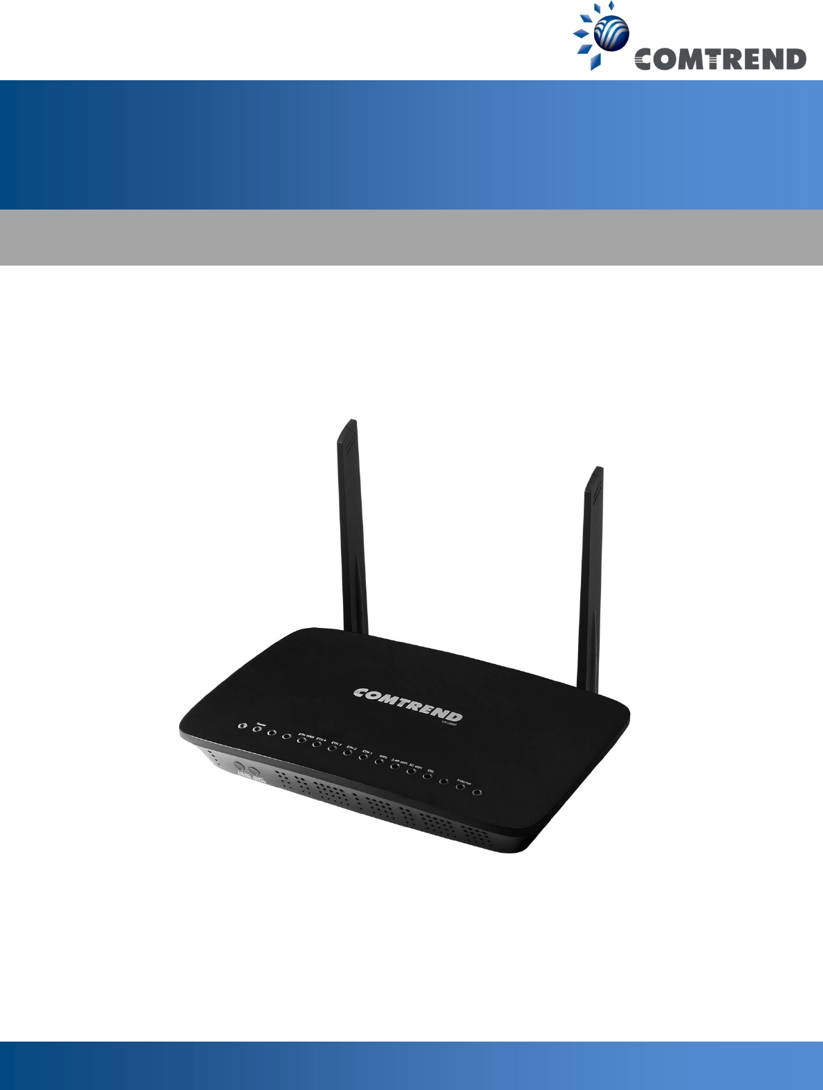
VR-3060 is a Multi-DSL solution for high-performance Internet access. In addition,
VR-3060 supports high power (400mw/26 dBm) dual bands (802.11n 2.4GHz &
802.11ac 5GHz) to create a large Wi-Fi footprint for the most seamless video
experience as well as blazing fast data speed and a toll-quality voice experience.

9
Chapter 2 Installation
2.1 Hardware Setup
Follow the instructions below to complete the hardware setup.
Non-stackable
This device is not stackable – do not place units on top of each other, otherwise
damage could occur.
BACK PANEL
The figure below shows the back panel of the device.
Power ON
Press the power button to the OFF position (OUT). Connect the power adapter to the
power port. Attach the power adapter to a wall outlet or other AC source. Press the
power button to the ON position (IN). If the Power LED displays as expected then
the device is ready for setup (see section 2.2 LED Indicators).
Caution 1: If the device fails to power up, or it malfunctions, first verify that the
power cords are connected securely and then power it on again. If the
problem persists, contact technical support.
Caution 2: Before servicing or disassembling this equipment, disconnect all power
cords and telephone lines from their outlets.
Reset Button
Restore the default parameters of the device by pressing the Reset button for 10
seconds. After the device has rebooted successfully, the front panel should display
as expected (see section 2.2 LED Indicators for details).
NOTE: If pressed down for more than 60 seconds, the VR-3060 will go into a
firmware update state (CFE boot mode). The firmware can then be
updated using an Internet browser pointed to the default IP address.

10
ETH WAN PORT
This port has the same features as the LAN ports described below with additional
Ethernet WAN functionality.
Ethernet (LAN) Ports
Use 1000-BASE-T RJ-45 cables to connect up to four network devices to a Gigabit
LAN, or 10/100BASE-T RJ-45 cables for standard network usage. These ports are
auto-sensing MDI/X; so either straight-through or crossover cable can be used.
USB Host Port (Type A)
This port can be used to connect the router to a printer, or supported USB devices.
DSL Port
Connect to an ADSL2/2+ or VDSL with this RJ11 Port. This device contains a micro
filter which removes the analog phone signal. If you wish, you can connect a
regular telephone to the same line by using a POTS splitter.
FRONT PANEL
2.4G WiFi On/Off & WPS Button
Press and release the WiFi-WPS button to activate WPS for the 2.4GHz WiFi
interface (make sure the WPS is enabled in Wireless->2.4GHz->Security page).
Press and hold WiFi-WPS button more than 10 seconds to enable/disable 2.4GHz
WiFi.
5G WiFi On/Off & WPS Button
Press and release the WiFi-WPS button to activate WPS for the 5GHz WiFi interface
(make sure the WPS is enabled in Wireless->5GHz->Security page).
Press and hold WiFi-WPS button more than 10 seconds to enable/disable 5GHz WiFi.
11
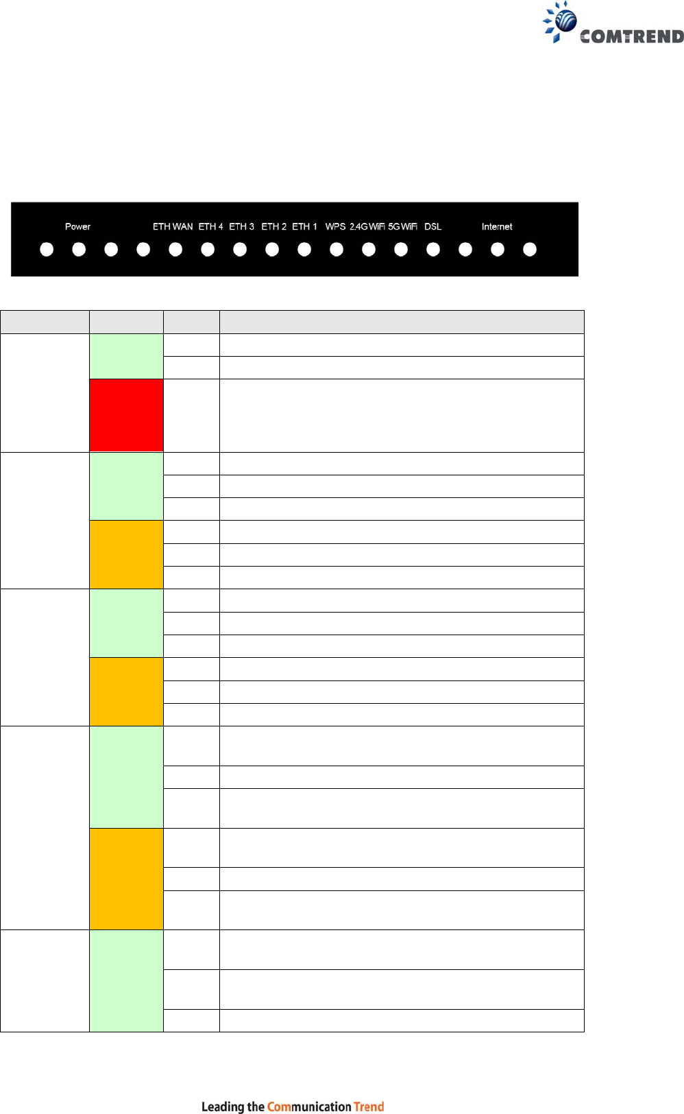
2.2 LED Indicators
The front panel LED indicators are shown below and explained in the following table.
This information can be used to check the status of the device and its connections.
LED Color Mode Function
POWER
GREEN On The device is powered up.
Off The device is powered down.
RED On
POST (Power On Self Test) failure or other
malfunction. A malfunction is any error of internal
sequence or state that will prevent the device from
connecting to the DSLAM or passing customer data.
ETH WAN
GREEN On WAN is connected in 1000 Mbps.
Off Ethernet WAN is not connected.
Blink In TX/RX over 1000 Mbps
ORANGE On Ethernet is connected in 10/100 Mbps.
Off Ethernet WAN is not connected.
Blink In TX/RX over 10/100 Mbps.
ETH 4 to 1
GREEN On Ethernet is connected at 1000 Mbps.
Off Ethernet is not connected.
Blink In TX/RX over 1000 Mbps.
ORANGE On Ethernet is connected at 10/100 Mbps.
Off Ethernet is not connected.
Blink In TX/RX over 10/100 Mbps.
WPS
GREEN
On WPS(2.4G) WPS enabled and client connected to
WLAN.
Off WPS(2.4G) WPS disabled.
Blink WPS(2.4G) WPS connection in progress, 120
seconds or until client connected.
ORANGE
On WPS(5G WPS enabled and client connected to
WLAN.
Off WPS(5G) WPS disabled.
Blink WPS(5G) WPS connection in progress, 120 seconds
or until client connected.
WiFi
2.4G GREEN
On The wireless module is ready.
(i.e. installed and enabled).
Off The wireless module is not ready.
(i.e. either not installed or disabled).
Blink Data transmitting or receiving over WLAN.
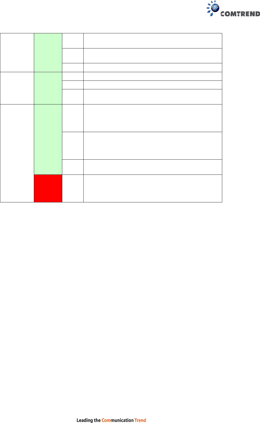
12
WiFi
5G GREEN
On The wireless module is ready.
(i.e. installed and enabled).
Off The wireless module is not ready.
(i.e. either not installed or disabled).
Blink Data transmitting or receiving over WLAN.
DSL GREEN
On xDSL Link is established.
Off xDSL Link is not established.
Blink The xDSL link is training or some traffic is passing
through xDSL.
INTERNET
GREEN
On IP connected and no traffic detected. If an IP or
PPPoE session is dropped due to an idle timeout,
the light will remain green if an ADSL connection is
still present.
Off Modem power off, modem in bridged mode or ADSL
connection not present. In addition, if an IP or
PPPoE session is dropped for any reason, other than
an idle timeout, the light is turned off.
Blink IP connected and IP Traffic is passing thru the
device (either direction)
RED On
Device attempted to become IP connected and
failed (no DHCP response, no PPPoE response,
PPPoE authentication failed, no IP address from
IPCP, etc.)

13
Chapter 3 Web User Interface
This section describes how to access the device via the web user interface (WUI)
using an Internet browser such as Internet Explorer (version 5.0 and later).
3.1 Default Settings
The factory default settings of this device are summarized below.
• LAN IP address: 192.168.1.1
• LAN subnet mask: 255.255.255.0
• Administrative access (username: root, password: 12345)
• User access (username: user, password: user)
• Remote (WAN) access (username: support, password: support)
• WLAN access: enabled
Technical Note
During power on, the device initializes all settings to default values. It will then
read the configuration profile from the permanent storage section of flash memory.
The default attributes are overwritten when identical attributes with different values
are configured. The configuration profile in permanent storage can be created via
the web user interface or telnet user interface, or other management protocols.
The factory default configuration can be restored either by pushing the reset button
for more than ten seconds until the power indicates LED blinking or by clicking the
Restore Default Configuration option in the Restore Settings screen.
14
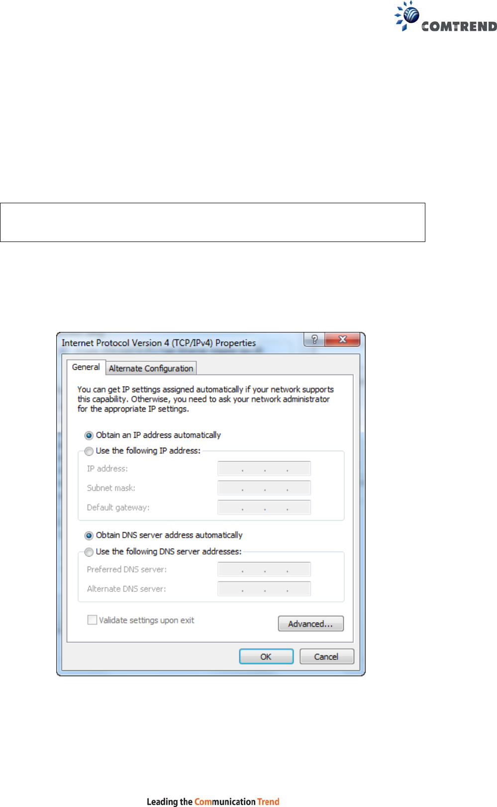
3.2 IP Configuration
DHCP MODE
When the VR-3060 powers up, the onboard DHCP server will switch on. Basically,
the DHCP server issues and reserves IP addresses for LAN devices, such as your PC.
To obtain an IP address from the DCHP server, follow the steps provided below.
NOTE: The following procedure assumes you are running Windows. However,
the general steps involved are similar for most operating systems (OS).
Check your OS support documentation for further details.
STEP 1: From the Network Connections window, open Local Area Connection (You
may also access this screen by double-clicking the Local Area Connection
icon on your taskbar). Click the Properties button.
STEP 2: Select Internet Protocol (TCP/IP) and click the Properties button.
STEP 3: Select Obtain an IP address automatically as shown below.
STEP 4: Click OK to submit these settings.
If you experience difficulty with DHCP mode, you can try static IP mode instead.
15
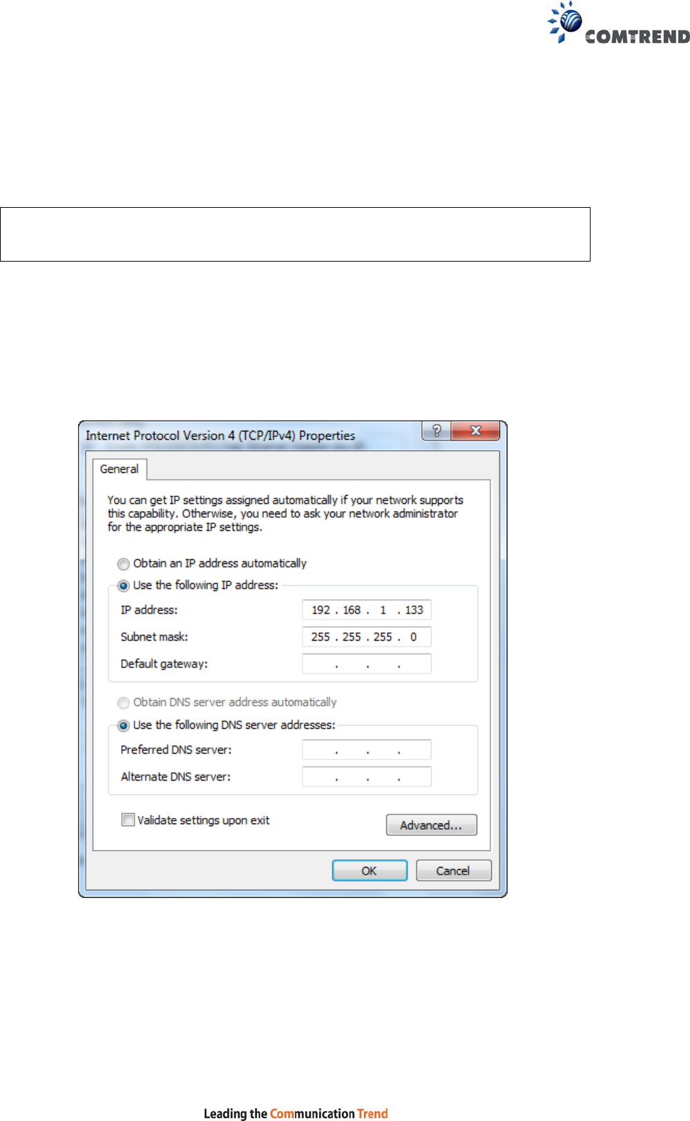
STATIC IP MODE
In static IP mode, you assign IP settings to your PC manually.
Follow these steps to configure your PC IP address to use subnet 192.168.1.x.
NOTE: The following procedure assumes you are running Windows. However,
the general steps involved are similar for most operating systems (OS).
Check your OS support documentation for further details.
STEP 1: From the Network Connections window, open Local Area Connection (You
may also access this screen by double-clicking the Local Area Connection
icon on your taskbar). Click the Properties button.
STEP 2: Select Internet Protocol (TCP/IP) and click the Properties button.
STEP 3: Change the IP address to the 192.168.1.x (1<x<255) subnet with subnet
mask of 255.255.255.0. The screen should now display as shown below.
STEP 4: Click OK to submit these settings.
16
3.3 Login Procedure
Perform the following steps to login to the web user interface.
NOTE: The default settings can be found in section 3.1 Default Settings.
STEP 1: Start the Internet browser and enter the default IP address for the device
in the Web address field. For example, if the default IP address is
192.168.1.1, type http://192.168.1.1.
NOTE: For local administration (i.e. LAN access), the PC running the browser
must be attached to the Ethernet, and not necessarily to the device.
For remote access (i.e. WAN), use the IP address shown on the Device
Information screen and login with remote username and password.
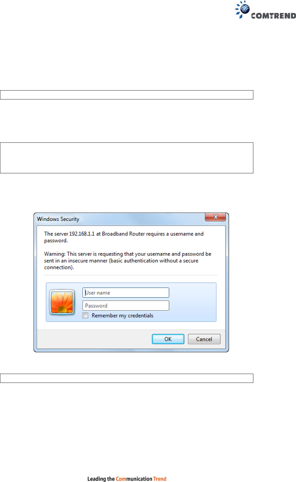
STEP 2: A dialog box will appear, such as the one below. Enter the default
username and password, as defined in section 3.1 Default Settings.
Click OK to continue.
NOTE: The login password can be changed later (see section 8.6.1 Accounts).
17
STEP 3: After successfully logging in for the first time, you will reach this screen.
You can also reach this page by clicking on the following icon located at the top of
the screen.
18
Chapter 4 Device Information
You can reach this page by clicking on the following icon located at the top of the
screen.
The web user interface window is divided into two frames, the main menu (on the
left) and the display screen (on the right). The main menu has several options and
selecting each of these options opens a submenu with more selections.
NOTE: The menu items shown are based upon the configured connection(s) and
user account privileges. For example, user account has limited access to
configuration modification.
Device Info is the first selection on the main menu so it will be discussed first.
Subsequent chapters will introduce the other main menu options in sequence.
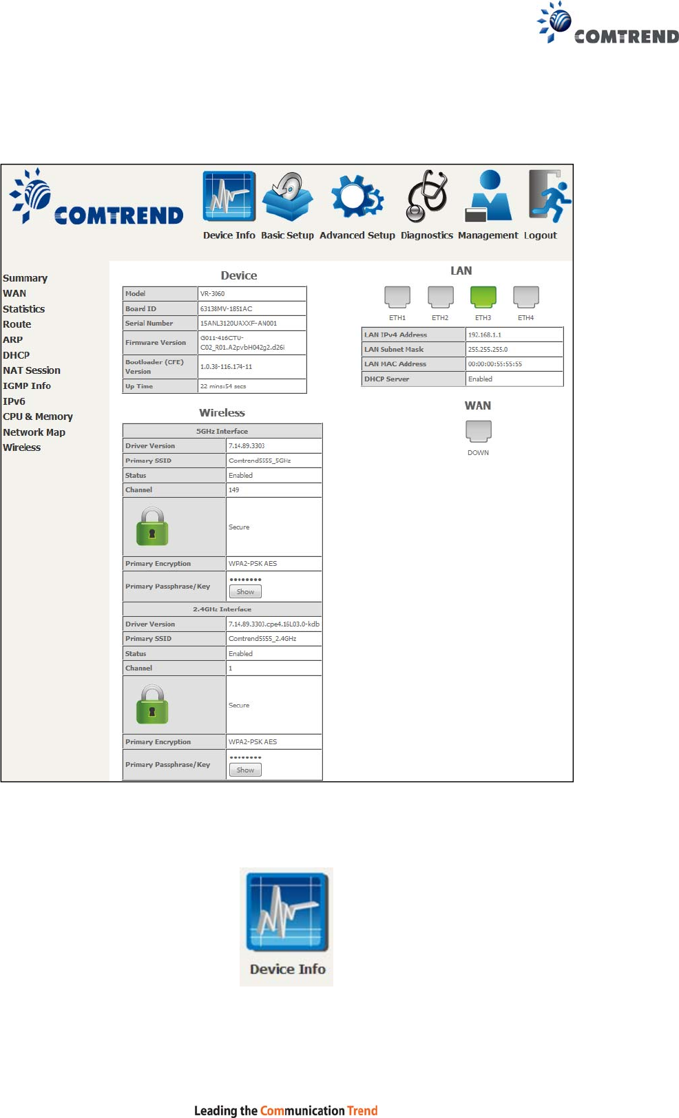
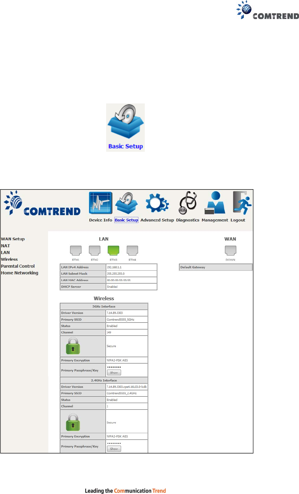
The Device Info Summary screen displays at startup.
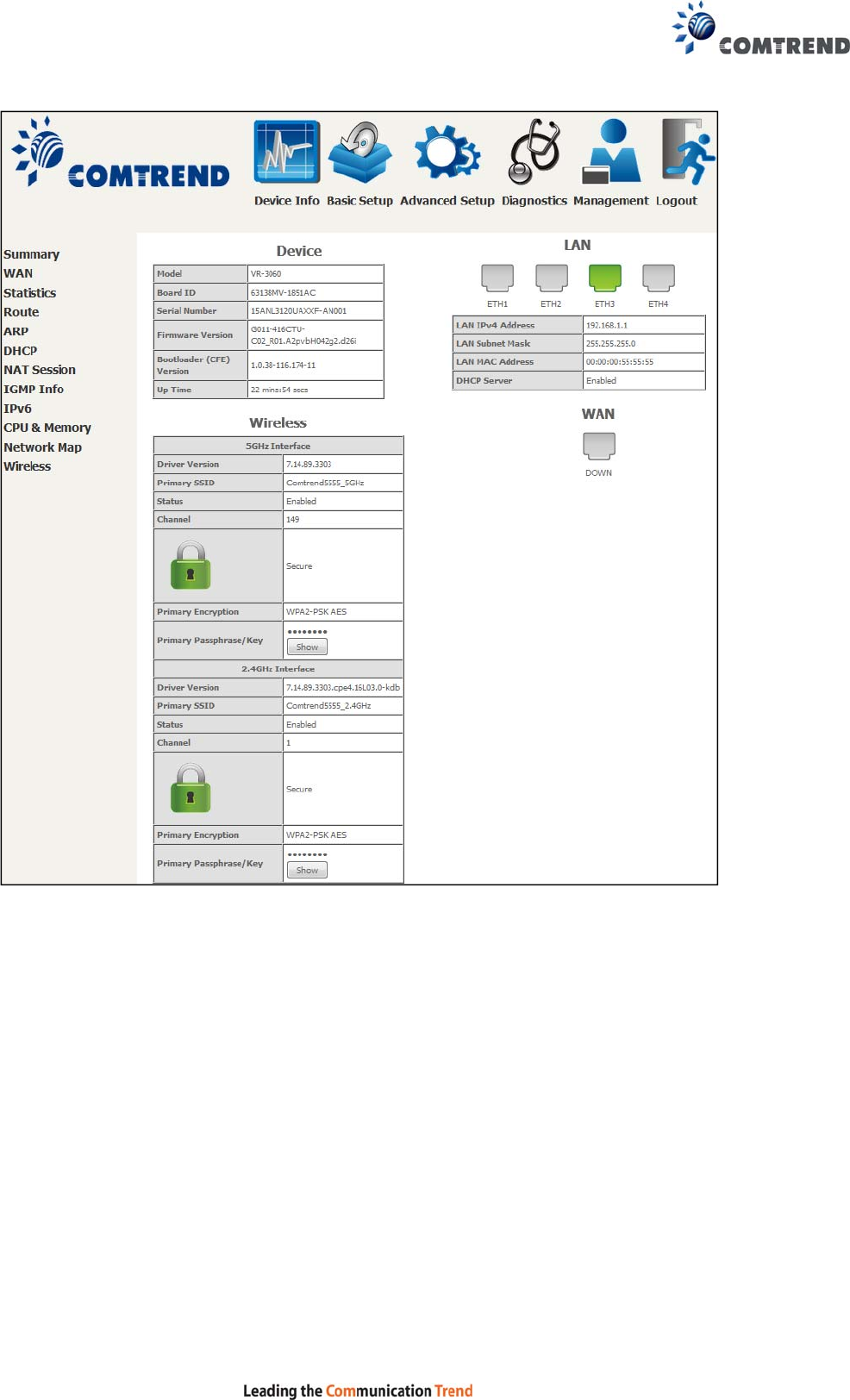
19
This screen shows hardware, software, IP settings and other related information.
20
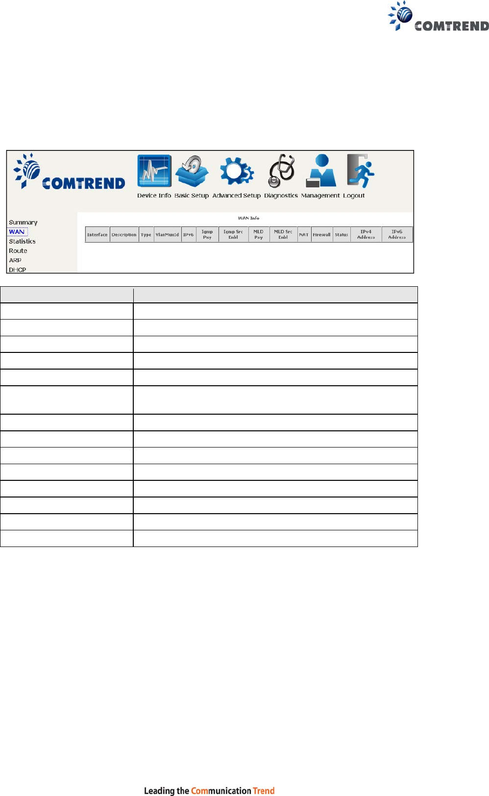
4.1 WAN
Select WAN from the Device Info submenu to display the configured PVC(s).
Heading Description
Interface Name of the interface for WAN
Description Name of the WAN connection
Type Shows the connection type
VlanMuxId Shows 802.1Q VLAN ID
IPv6 Shows WAN IPv6 status
Igmp Pxy Shows Internet Group Management Protocol (IGMP)
proxy status
Igmp Src Enbl Shows the status of WAN interface used as IGMP source
MLD Pxy Shows Multicast Listener Discovery (MLD) proxy status
MLD Src Enbl Shows the status of WAN interface used as MLD source
NAT Shows Network Address Translation (NAT) status
Firewall Shows the status of Firewall
Status Lists the status of DSL link
IPv4 Address Shows WAN IPv4 address
IPv6 Address Shows WAN IPv6 address
21
4.2 Statistics
This selection provides LAN, WAN, ATM and xDSL statistics.
NOTE: These screens are updated automatically every 15 seconds.
Click Reset Statistics to perform a manual update.
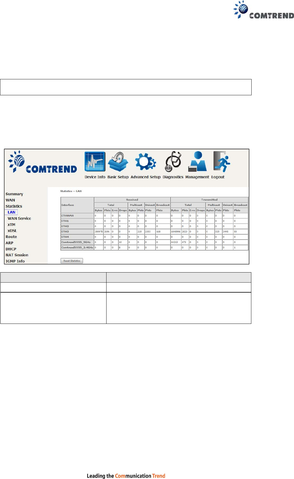
4.2.1 LAN Statistics
This screen shows data traffic statistics for each LAN interface.
Heading Description
Interface LAN interface(s)
Received/Transmitted: - Bytes
- Pkts
- Errs
- Drops
Number of Bytes
Number of Packets
Number of packets with errors
Number of dropped packets
22
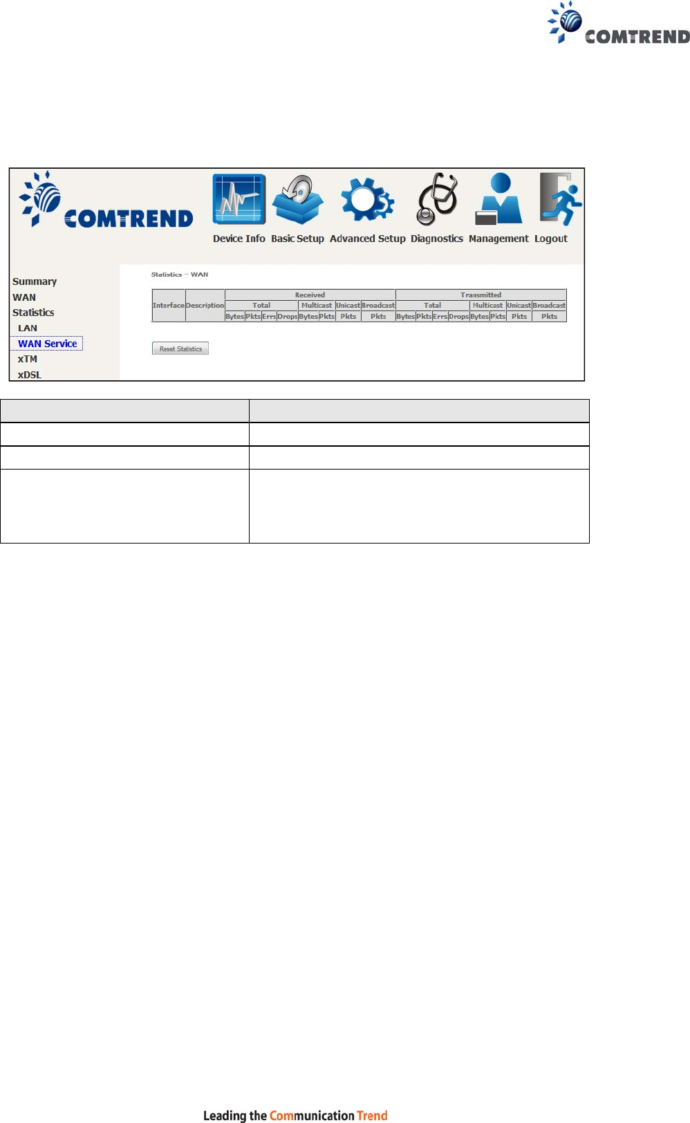
4.2.2 WAN Service
This screen shows data traffic statistics for each WAN interface.
Heading Description
Interface WAN interfaces
Description WAN service label
Received/Transmitted - Bytes
- Pkts
- Errs
- Drops
Number of Bytes
Number of Packets
Number of packets with errors
Number of dropped packets
23
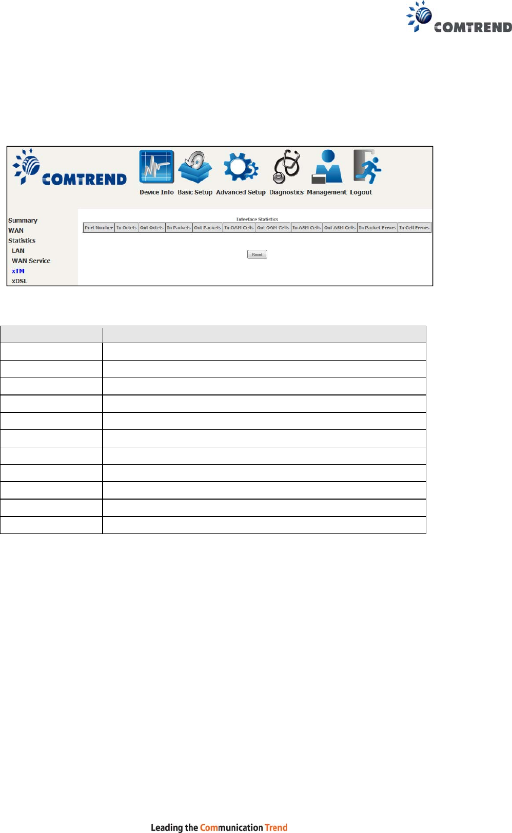
4.2.3 XTM Statistics
The following figure shows ATM (Asynchronous Transfer Mode)/PTM (Packet
Transfer Mode) statistics.
XTM Interface Statistics
Heading Description
Port Number ATM PORT (0-1)
In Octets Number of octets received over the interface
Out Octets Number of octets transmitted over the interface
In Packets Number of packets received over the interface
Out Packets Number of packets transmitted over the interface
In OAM Cells Number of OAM Cells received over the interface
Out OAM Cells Number of OAM Cells transmitted over the interface
In ASM Cells Number of ASM Cells received over the interface
Out ASM Cells Number of ASM Cells transmitted over the interface
In Packet Errors Number of packets in Error
In Cell Errors Number of cells in Error
24
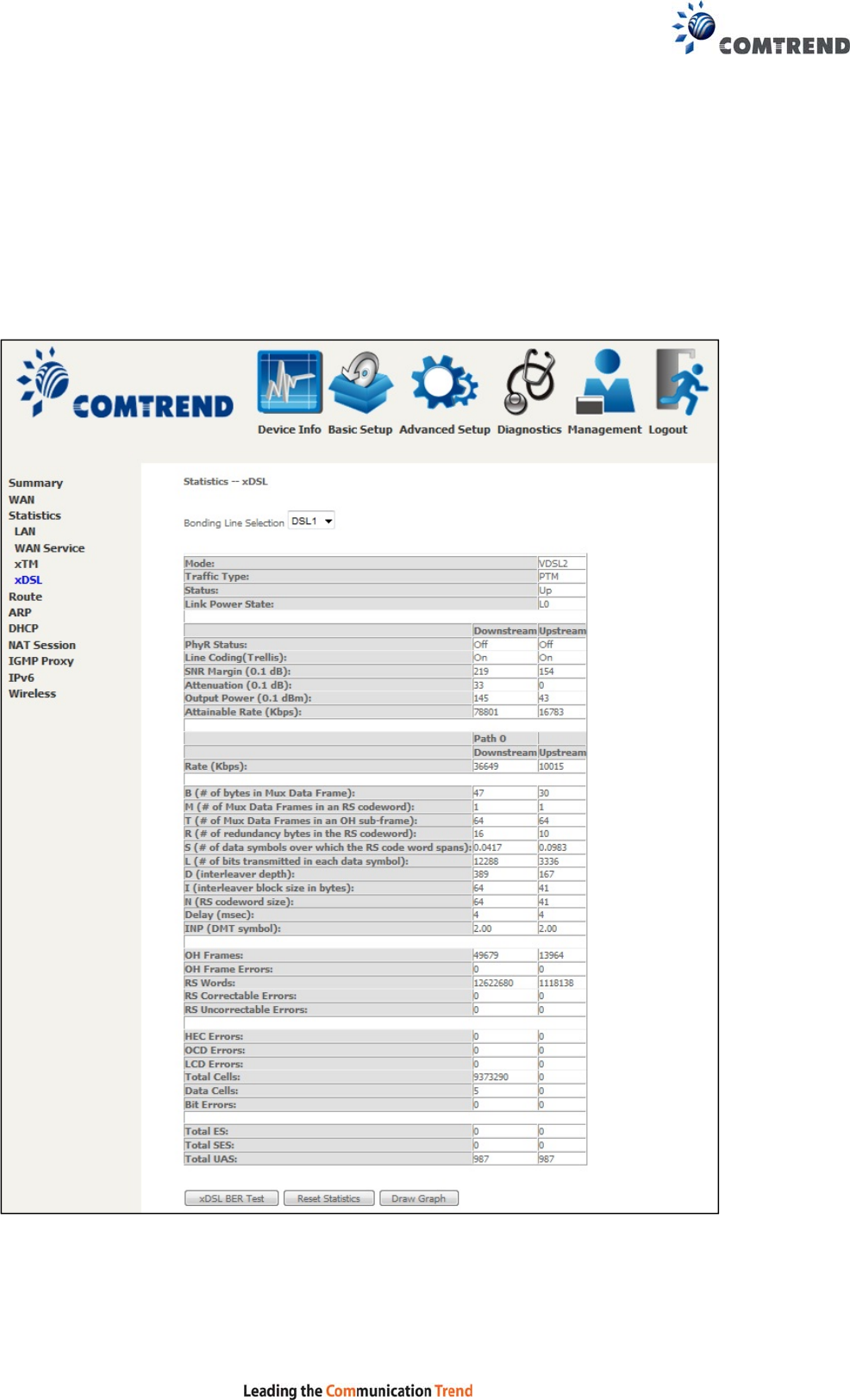
4.2.4 xDSL Statistics
The xDSL Statistics screen displays information corresponding to the xDSL type.
The two examples below (VDSL & ADSL) show this variation.
VDSL
25
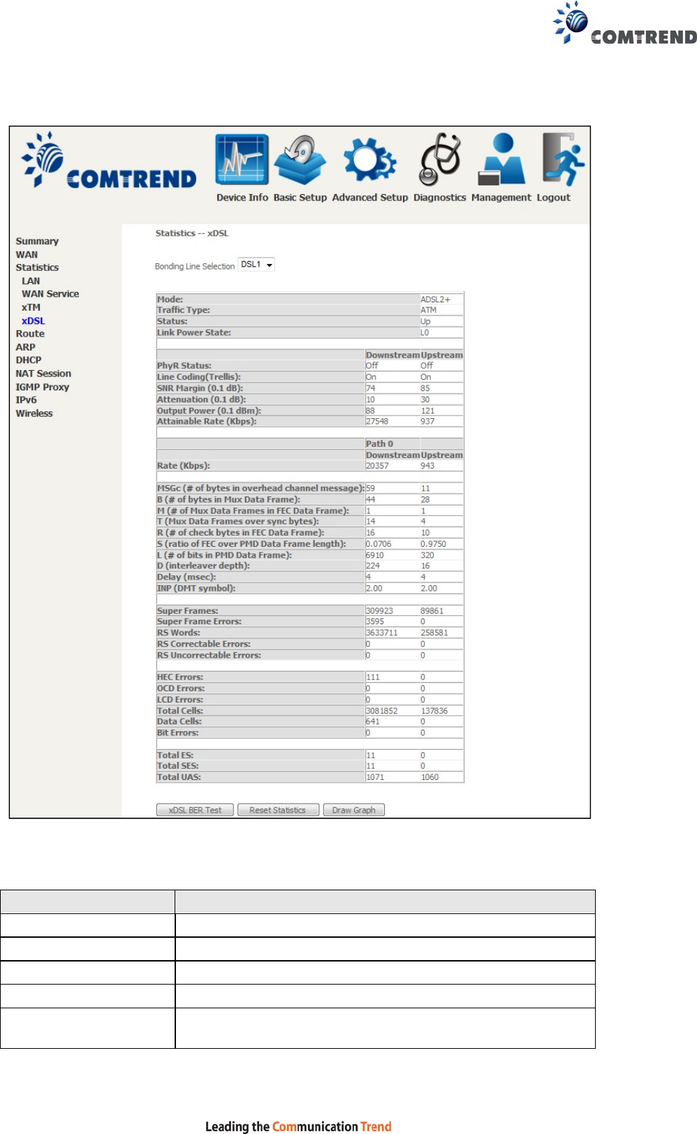
ADSL
Click the Reset Statistics button to refresh this screen.
Field Description
Mode VDSL, VDSL2
Traffic Type ATM, PTM
Status Lists the status of the DSL link
Link Power State Link output power state
phyR Status Shows the status of PhyR™ (Physical Layer
Re-Transmission) impulse noise protection

26
Field Description
Line Coding (Trellis) Trellis On/Off
SNR Margin (0.1 dB) Signal to Noise Ratio (SNR) margin
Attenuation (0.1 dB) Estimate of average loop attenuation in the downstream
direction
Output Power
(0.1 dBm) Total upstream output power
Attainable Rate (Kbps) The sync rate you would obtain
Rate (Kbps) Current sync rates downstream/upstream
In VDSL mode, the following section is inserted.
MSGc Number of bytes in overhead channel message
B Number of bytes in Mux Data Frame
M Number of Mux Data Frames in a RS codeword
T Number of Mux Data Frames in an OH sub-frame
R Number of redundancy bytes in the RS codeword
S Number of data symbols the RS codeword spans
L Number of bits transmitted in each data symbol
D The interleaver depth
I The interleaver block size in bytes
N RS codeword size
Delay The delay in milliseconds (msec)
INP DMT symbol
Super Frames Total number of super frames
Super Frame Errors Number of super frames received with errors
RS Words Total number of Reed-Solomon code errors
RS Correctable Errors Total Number of RS with correctable errors
RS Uncorrectable Errors
Total Number of RS words with uncorrectable errors
OH Frames Total number of OH frames
OH Frame Errors Number of OH frames received with errors
RS Words Total number of Reed-Solomon code errors
RS Correctable Errors Total Number of RS with correctable errors
RS Uncorrectable Errors
Total Number of RS words with uncorrectable errors
HEC Errors Total Number of Header Error Checksum errors
OCD Errors Total Number of Out-of-Cell Delineation errors
LCD Errors Total number of Loss of Cell Delineation
Total Cells Total number of ATM cells (including idle + data cells)
Data Cells Total number of ATM data cells
Bit Errors Total number of bit errors
27
Total ES Total Number of Errored Seconds
Total SES Total Number of Severely Errored Seconds
Total UAS Total Number of Unavailable Seconds
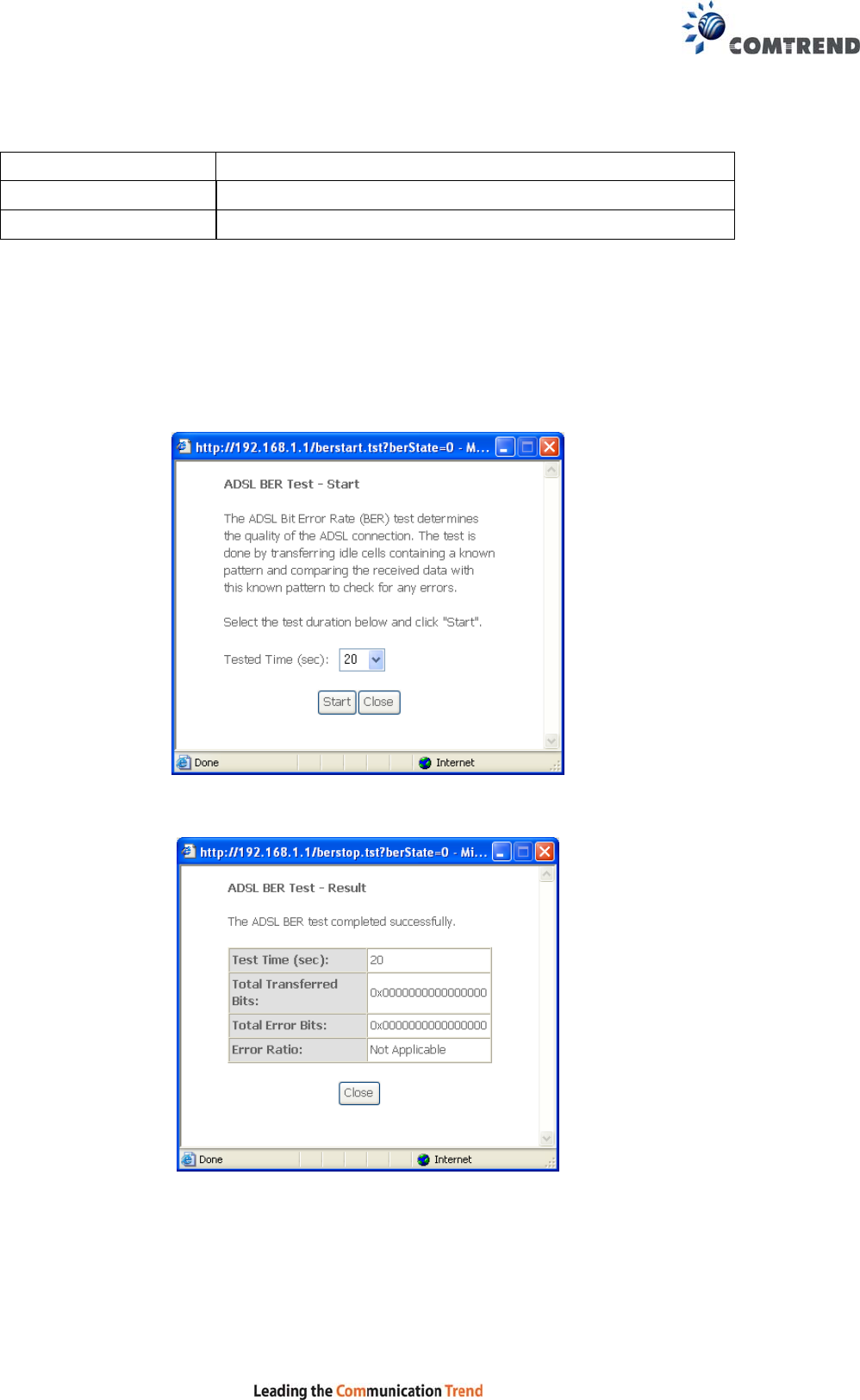
xDSL BER TEST
Click xDSL BER Test on the xDSL Statistics screen to test the Bit Error Rate (BER).
A small pop-up window will open after the button is pressed, as shown below.
Click Start to start the test or click Close to cancel the test. After the BER testing is
complete, the pop-up window will display as follows.
28
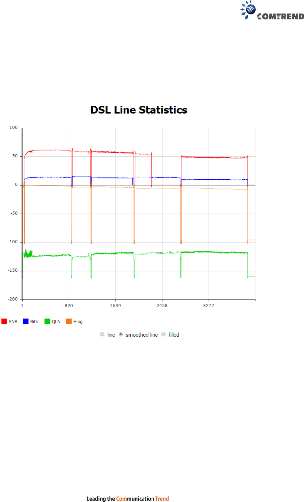
xDSL TONE GRAPH
Click Draw Graph on the xDSL Statistics screen and a pop-up window will display
the xDSL statistics graph, including SNR, Bits per tone, QLN and Hlog of the xDSL
line connection, as shown below.
29
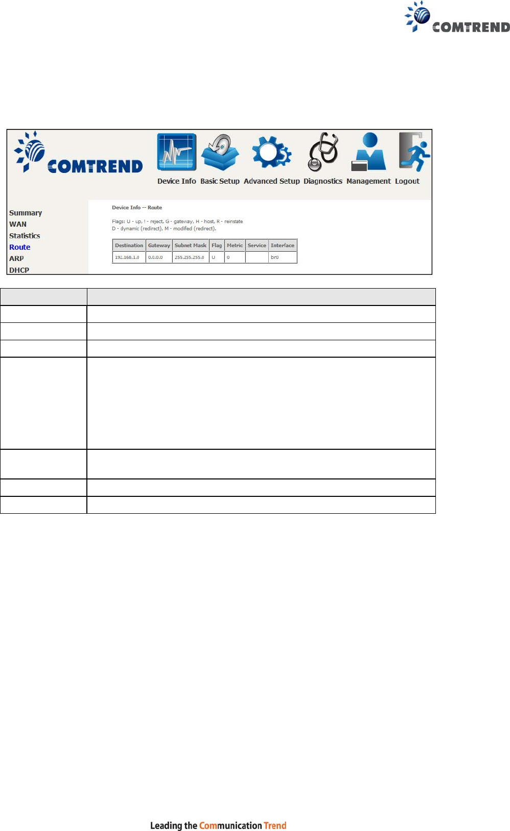
4.3 Route
Choose Route to display the routes that the VR-3060 has found.
Field Description
Destination Destination network or destination host
Gateway Next hop IP address
Subnet Mask Subnet Mask of Destination
Flag U: route is up
!: reject route
G: use gateway
H: target is a host
R: reinstate route for dynamic routing
D: dynamically installed by daemon or redirect
M: modified from routing daemon or redirect
Metric The 'distance' to the target (usually counted in hops). It is not
used by recent kernels, but may be needed by routing daemons.
Service Shows the WAN connection label
Interface Shows connection interfaces
30
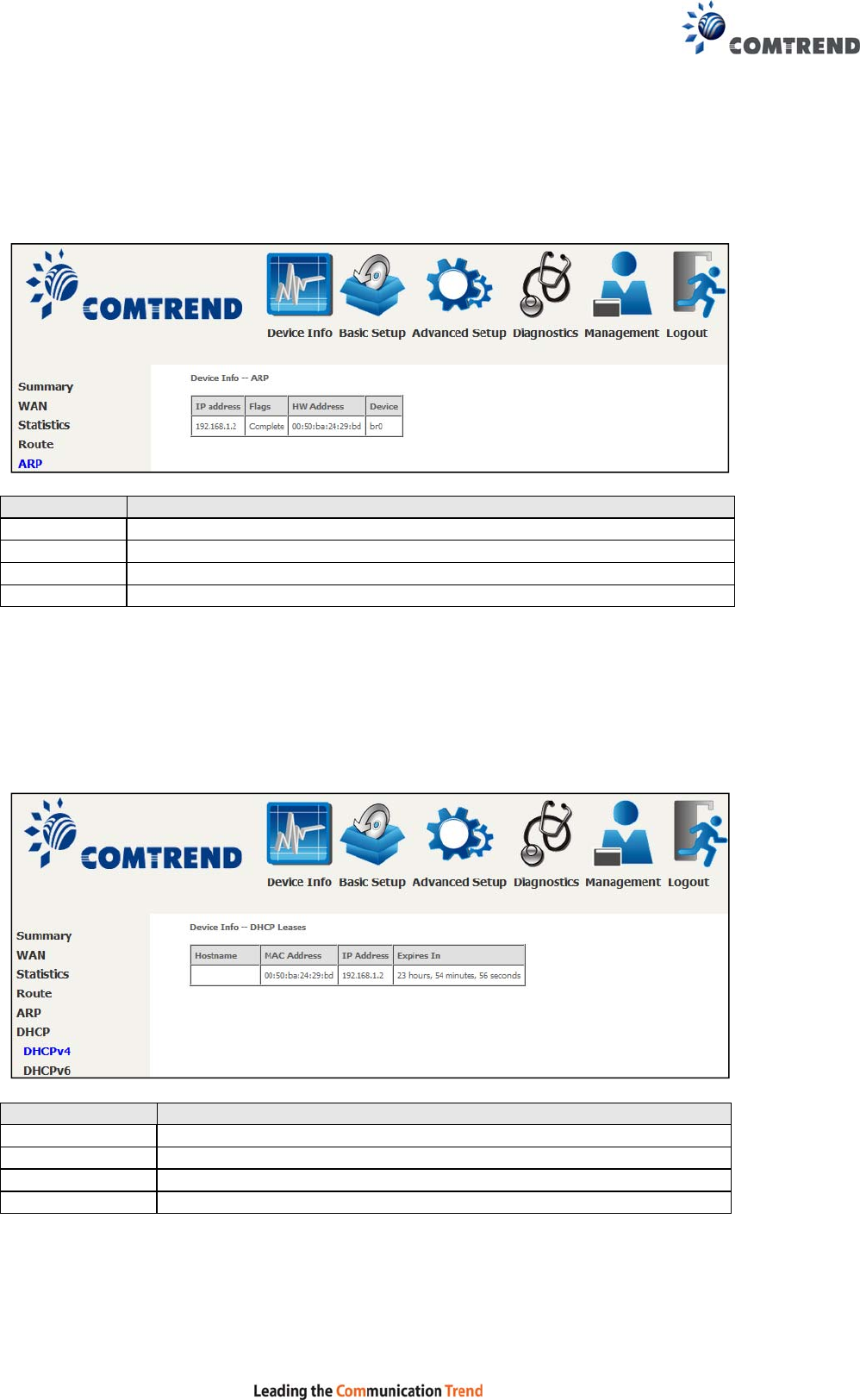
4.4 ARP
Click ARP to display the ARP information.
Field Description
IP address Shows IP address of host PC
Flags Complete, Incomplete, Permanent, or Publish
HW Address Shows the MAC address of host PC
Device Shows the connection interface
4.5 DHCP
Click DHCP to display all DHCP Leases.
Field Description
Hostname Shows the device/host/PC network name
MAC Address Shows the Ethernet MAC address of the device/host/PC
IP Address Shows IP address of device/host/PC
Expires In Shows how much time is left for each DHCP Lease
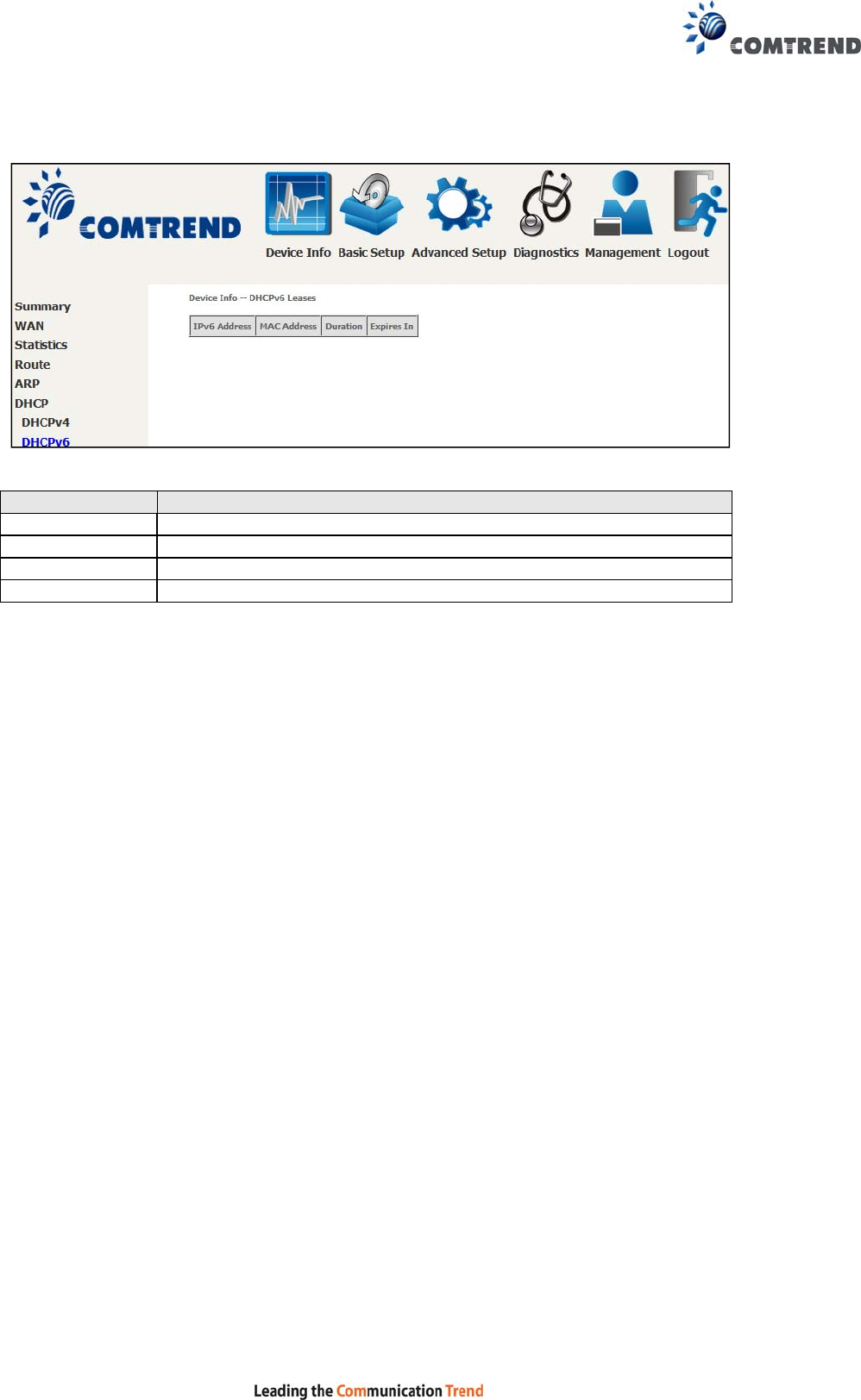
31
Field Description
IPv6 Address Shows IP address of device/host/PC
MAC Address Shows the Ethernet MAC address of the device/host/PC
Duration Shows leased time in hours
Expires In Shows how much time is left for each DHCP Lease
32
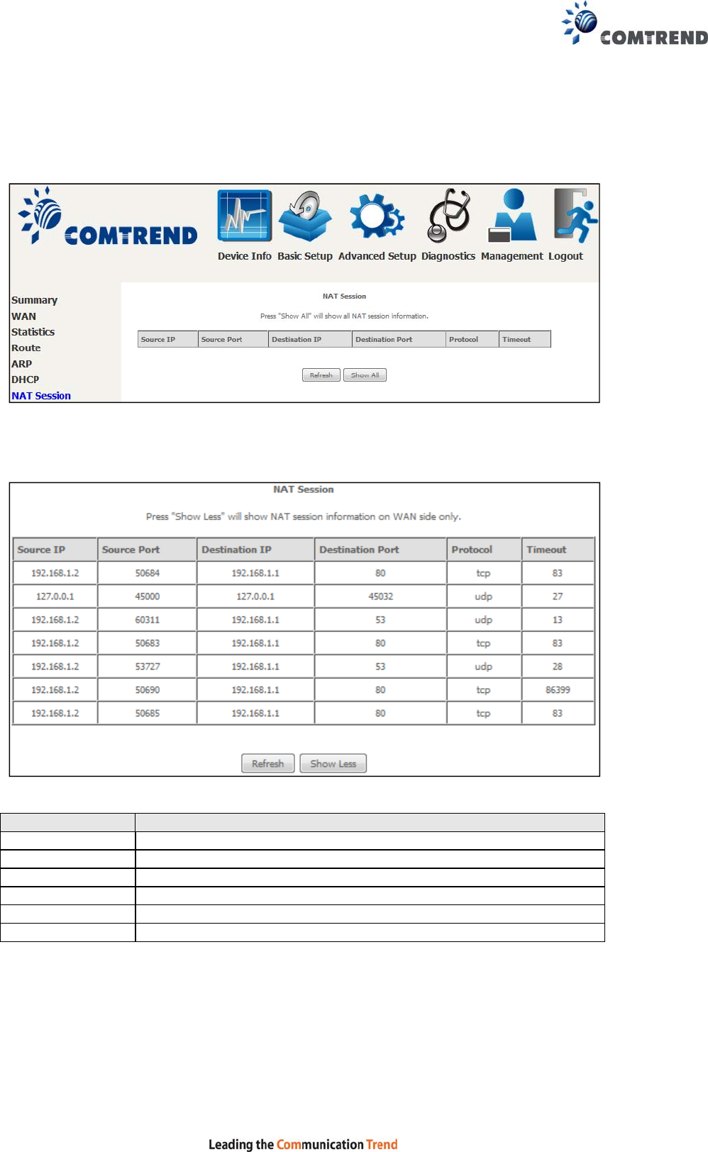
4.6 NAT Session
This page displays all NAT connection session including both UPD/TCP protocols
passing through the device.
Click the “Show All” button to display the following.
Field Description
Source IP The source IP from which the NAT session is established
Source Port The source port from which the NAT session is established
Destination IP
The IP which the NAT session was connected to
Destination Port The port which the NAT session was connected to
Protocol The Protocol used in establishing the particular NAT session
Timeout The time remaining for the TCP/UDP connection to be active
33
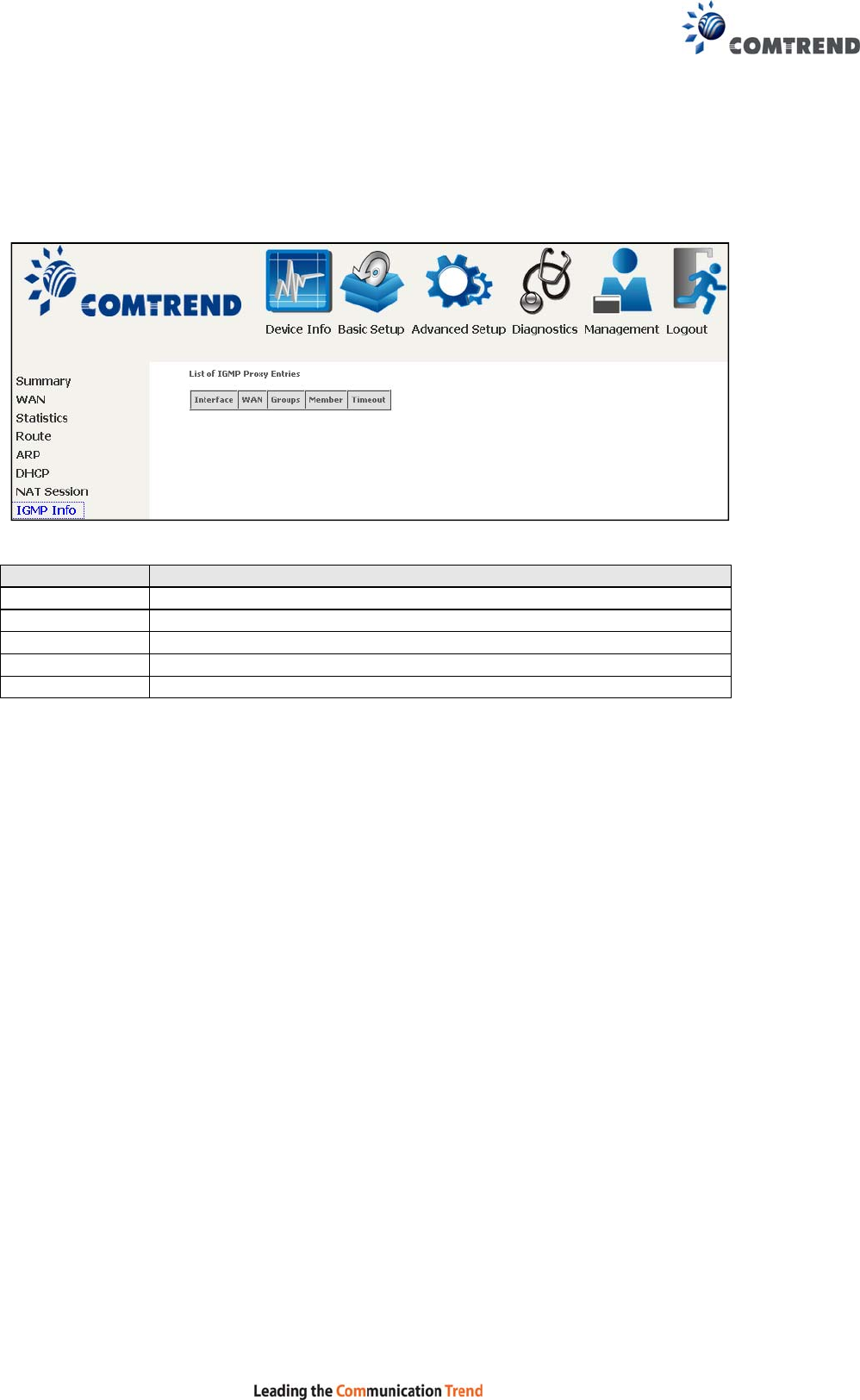
4.7 IGMP Info
Click IGMP Info to display the list of IGMP entries broadcasting through IGMP proxy
enabled wan connection.
Field Description
Interface The Source interface from which the IGMP report was received
WAN The WAN interface from which the multicast traffic is received
Groups The destination IGMP group address
Member The Source IP from which the IGMP report was received
Timeout The time remaining before the IGMP report expires
34
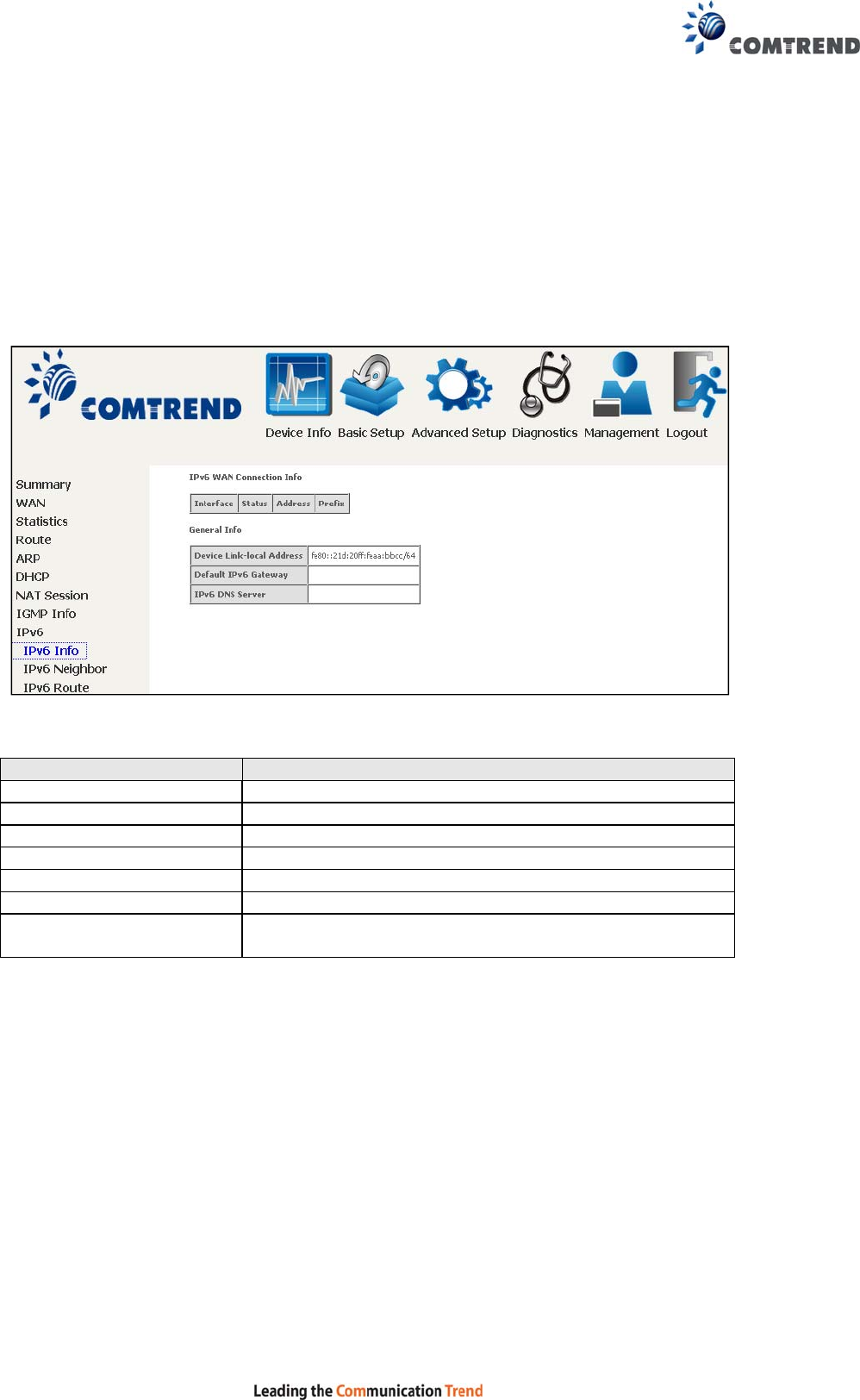
4.8 IPv6
4.8.1 IPv6 Info
Click IPv6 Info to display the IPv6 WAN connection info.
Field Description
Interface WAN interface with IPv6 enabled
Status Connection status of the WAN interface
Address IPv6 Address of the WAN interface
Prefix Prefix received/configured on the WAN interface
Device Link-local Address
The CPE's LAN Address
Default IPv6 Gateway The default WAN IPv6 gateway
IPv6 DNS Server The IPv6 DNS servers received from the WAN interface
/ configured manually
35
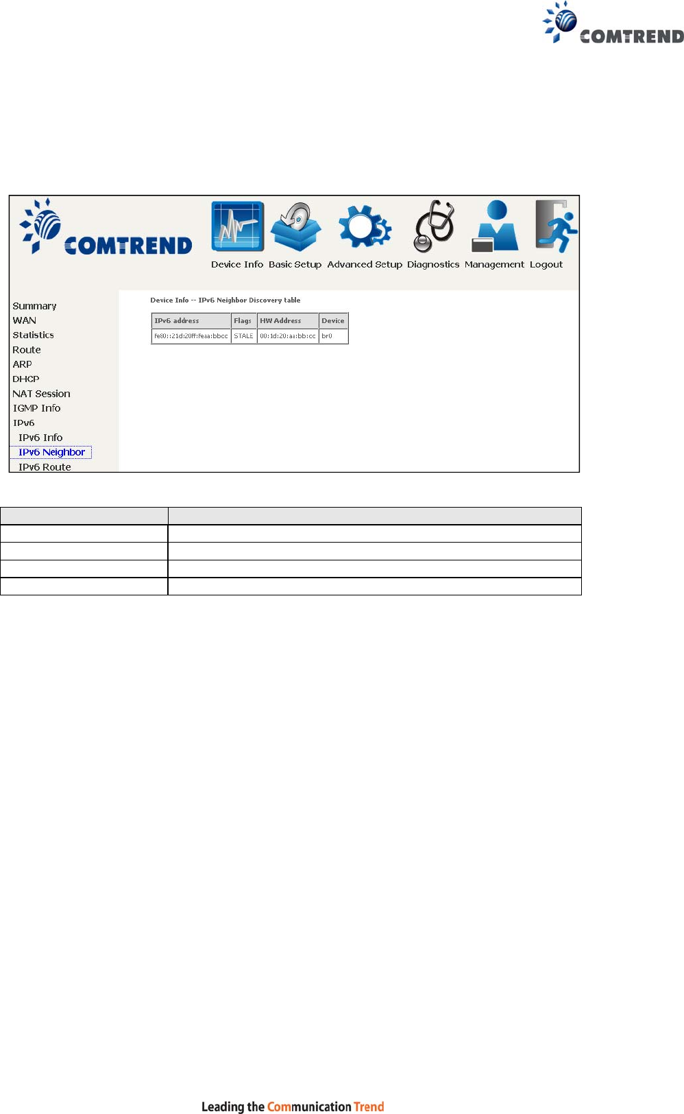
4.8.2 IPv6 Neighbor
Click IPv6 Neighbor to display the list of IPv6 nodes discovered.
Field Description
IPv6 Address Ipv6 address of the device(s) found
Flags Status of the neighbor device
HW Address MAC address of the neighbor device
Device Interface from which the device is located
36
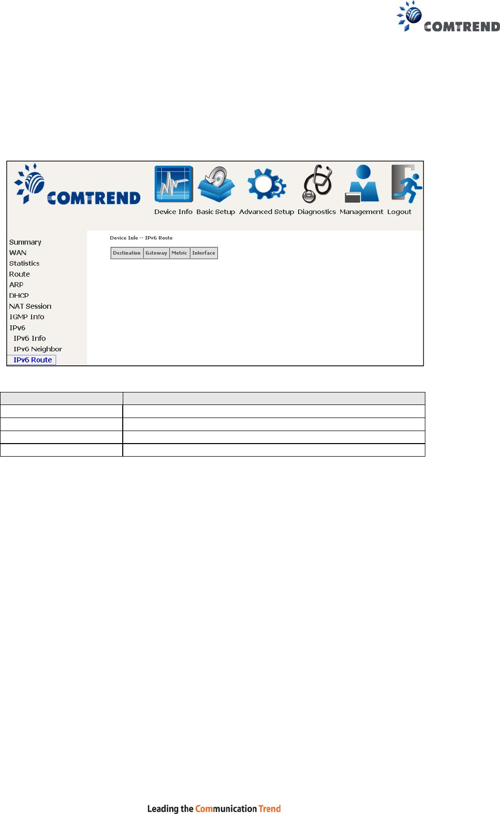
4.8.3 IPv6 Route
Click IPv6 Route to display the IPv6 route info.
Field Description
Destination Destination IP Address
Gateway Gateway address used for destination IP
Metric Metric specified for gateway
Interface Interface used for destination IP
37
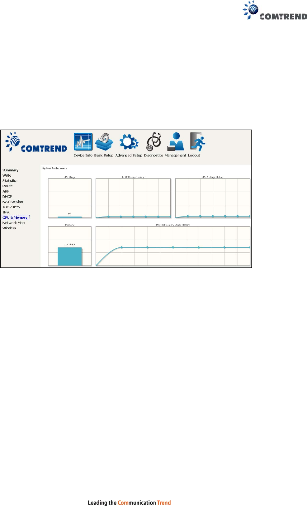
4.9 CPU & Memory
Displays the system performance graphs. Shows the current loading of the CPU and
memory usage with dynamic updates.
Note: This graph is unavailable for Internet Explorer users.
38
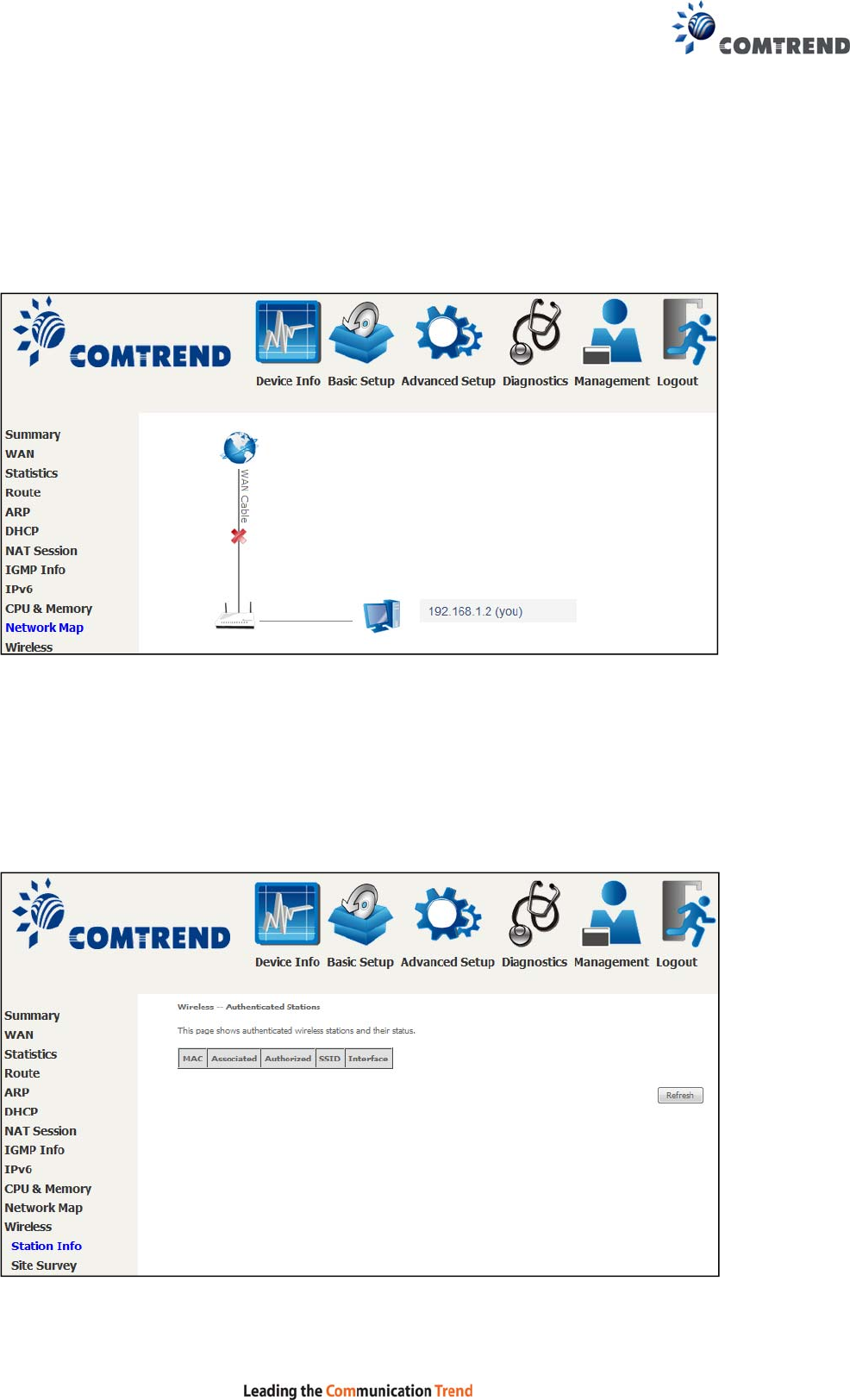
4.10 Network Map
The network map is a graphical representation of router’s wan status and LAN
devices.
Note: This graph is unavailable for Internet Explorer users.
4.11 Wireless
4.11.1 Station Info
This page shows authenticated wireless stations and their status. Click the Refresh
button to update the list of stations in the WLAN.

39
Consult the table below for descriptions of each column heading.
Field Description
MAC Lists the MAC address of all the stations.
Associated Lists all the stations that are associated with the Access
Point, along with the amount of time since packets were
transferred to and from each station. If a station is idle for
too long, it is removed from this list.
Authorized Lists those devices with authorized access.
SSID Lists which SSID of the modem that the stations connect
to.
Interface Lists which interface of the modem that the stations
connect to.
40
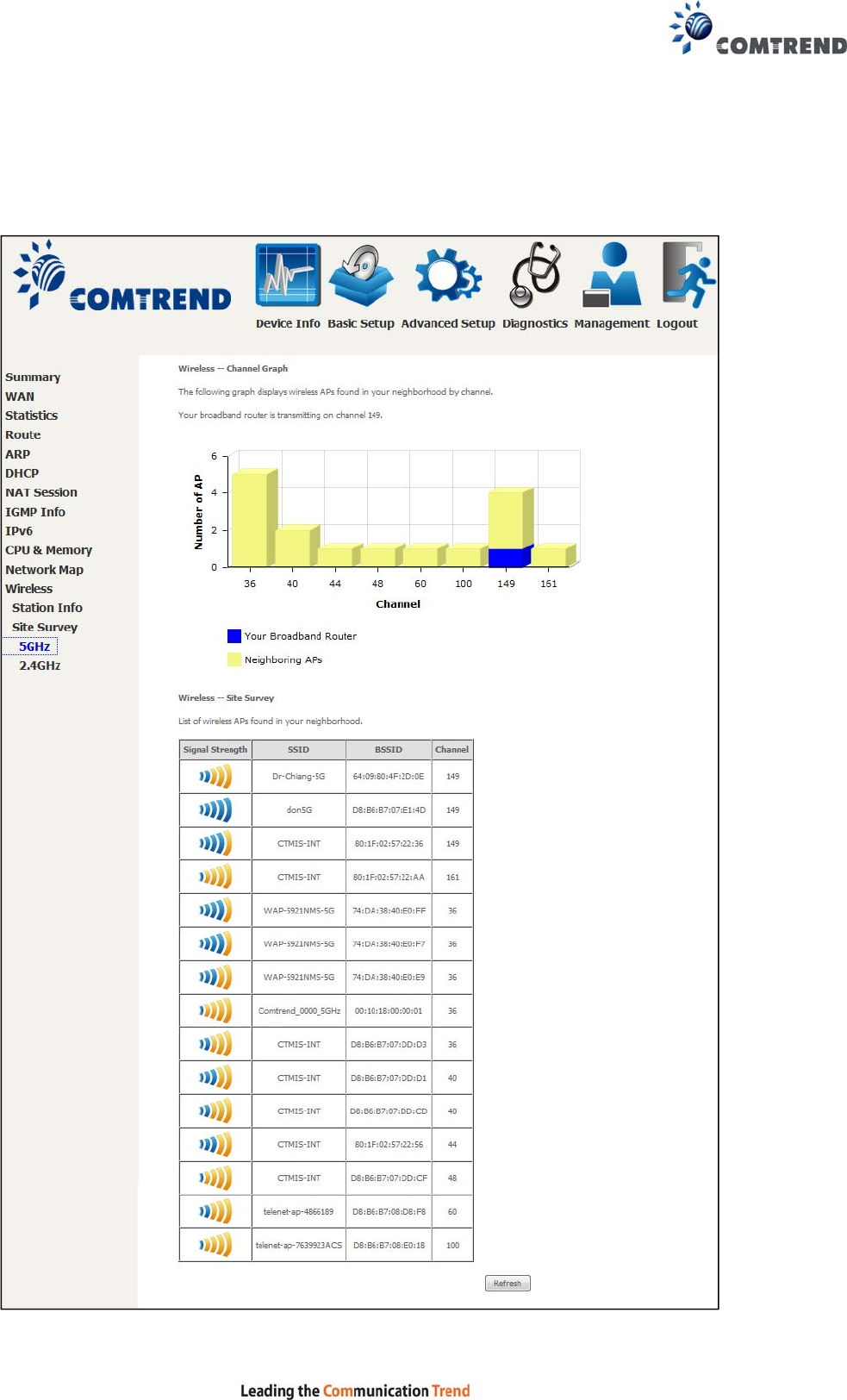
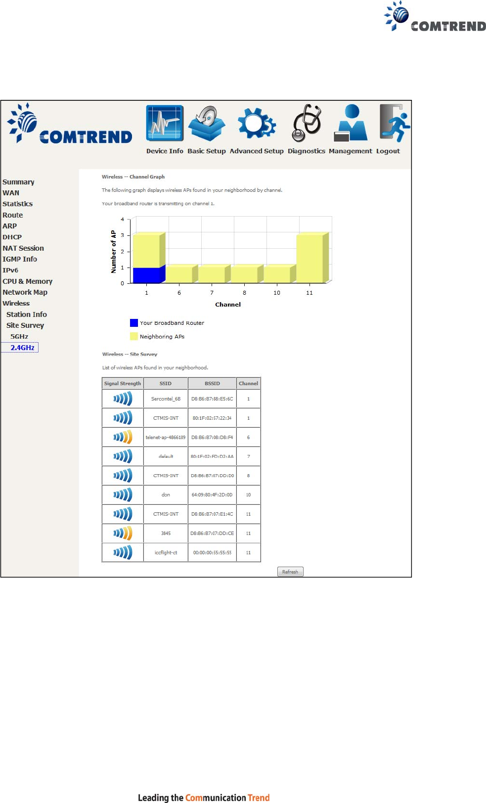
4.11.2 Site Survey
The graph displays wireless APs found in your neighborhood by channel.
5GHz
41
2.4GHz
42
Chapter 5 Basic Setup
You can reach this page by clicking on the following icon located at the top of the
screen.
This will bring you to the following screen.
43
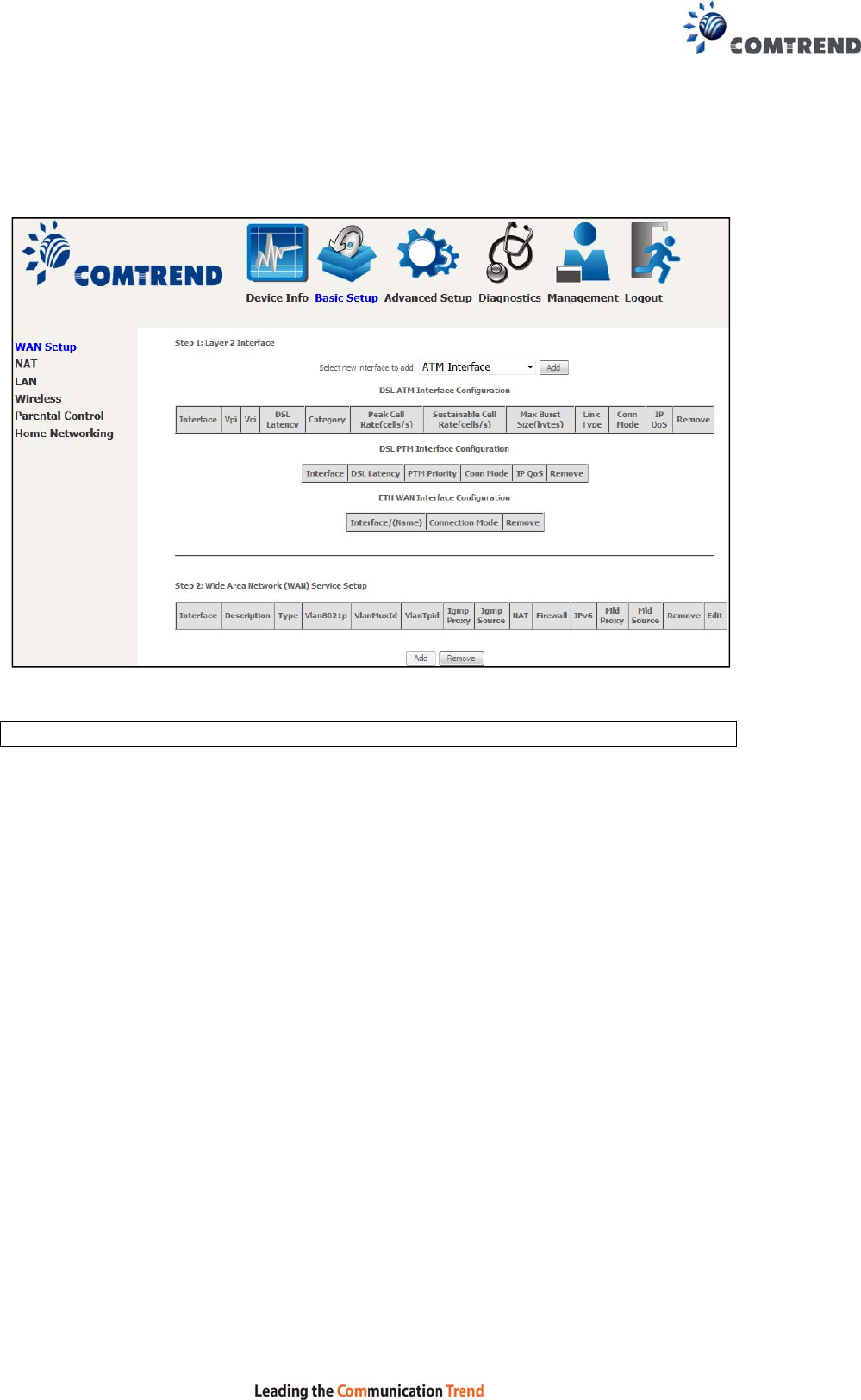
5.1 Wan Setup
Add or remove ATM, PTM and ETH WAN interface connections here.
Click Add to create a new Layer 2 Interface (see Appendix F - Connection Setup).
NOTE: Up to 8 ATM interfaces can be created and saved in flash memory.
To remove a connection, click the Remove button.
44
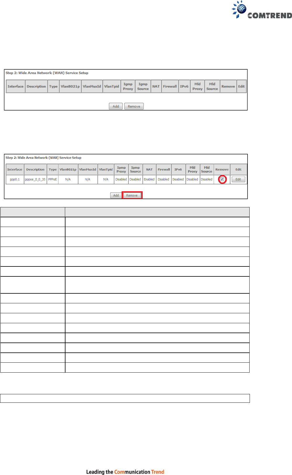
5.1.1 WAN Service Setup
This screen allows for the configuration of WAN interfaces.
Click the Add button to create a new connection. For connections on ATM or PTM or
ETH WAN interfaces see Appendix F - Connection Setup.
To remove a connection, select its Remove column radio button and click Remove.
Heading Description
Interface Name of the interface for WAN
Description Name of the WAN connection
Type Shows the connection type
Vlan8021p VLAN ID is used for VLAN Tagging (IEEE 802.1Q)
VlanMuxId Shows 802.1Q VLAN ID
VlanTpid VLAN Tag Protocol Identifier
IGMP Proxy Shows Internet Group Management Protocol (IGMP) Proxy
status
IGMP Source Shows the status of WAN interface used as IGMP source
NAT Shows Network Address Translation (NAT) status
Firewall Shows the Security status
IPv6 Shows the WAN IPv6 address
MLD Proxy Shows Multicast Listener Discovery (MLD) Proxy status
Mld Source Shows the status of WAN interface used as MLD source
Remove Select interfaces to remove
Edit Click the Edit button to make changes to the WAN interface.
To remove a connection, select its Remove column radio button and click Remove.
NOTE: Up to 16 PVC profiles can be configured and saved in flash memory.
45
5.2 NAT
For NAT features under this section to work, NAT must be enabled in at least one
PVC.
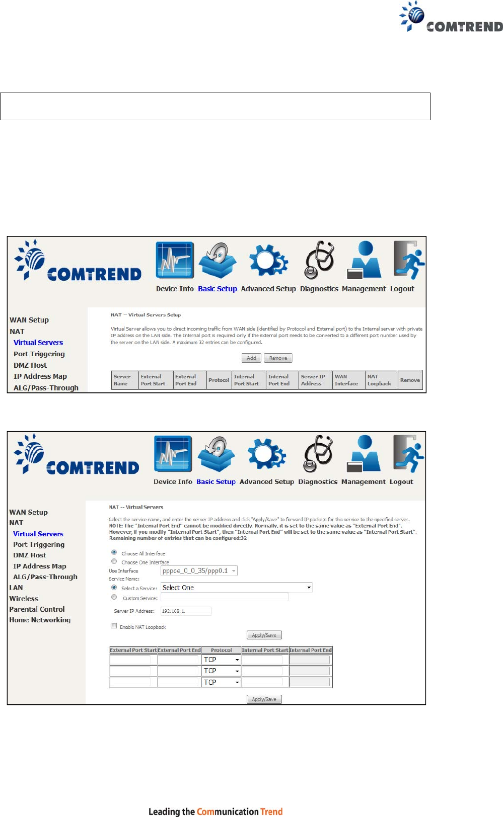
5.2.1 Virtual Servers
Virtual Servers allow you to direct incoming traffic from the WAN side (identified by
Protocol and External port) to the internal server with private IP addresses on the
LAN side. The Internal port is required only if the external port needs to be
converted to a different port number used by the server on the LAN side.
A maximum of 32 entries can be configured.
To add a Virtual Server, click Add. The following will be displayed.
Click Apply/Save to apply and save the settings.

46
Consult the table below for field and header descriptions.
Field/Header Description
Choose All InterfaceVirtual server rules will be created for all WAN interfaces.
Choose One Interface
Use Interface
Select a WAN interface from the drop-down menu.
Select a Service
Or
Custom Service
User should select the service from the list.
Or
User can enter the name of their choice.
Server IP Address Enter the IP address for the server.
Enable NAT Loopback Allows local machines to access virtual server via WAN IP
Address
External Port Start Enter the starting external port number (when you select
Custom Server). When a service is selected, the port
ranges are automatically configured.
External Port End Enter the ending external port number (when you select
Custom Server). When a service is selected, the port
ranges are automatically configured.
Protocol TCP, TCP/UDP, or UDP.
Internal Port Start Enter the internal port starting number (when you select
Custom Server). When a service is selected the port ranges
are automatically configured
Internal Port End Enter the internal port ending number (when you select
Custom Server). When a service is selected, the port
ranges are automatically configured.
47
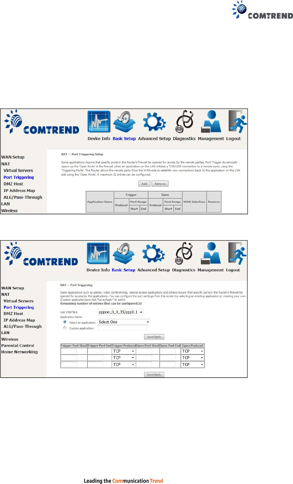
5.2.2 Port Triggering
Some applications require that specific ports in the firewall be opened for access by
the remote parties. Port Triggers dynamically 'Open Ports' in the firewall when an
application on the LAN initiates a TCP/UDP connection to a remote party using the
'Triggering Ports'. The Router allows the remote party from the WAN side to
establish new connections back to the application on the LAN side using the 'Open
Ports'. A maximum 32 entries can be configured.
To add a Trigger Port, click Add. The following will be displayed.
Click Save/Apply to save and apply the settings.
Consult the table below for field and header descriptions.

48
Field/Header Description
Use Interface Select a WAN interface from the drop-down menu.
Select an Application
Or
Custom Application
User should select the application from the list.
Or
User can enter the name of their choice.
Trigger Port Start Enter the starting trigger port number (when you select
custom application). When an application is selected, the
port ranges are automatically configured.
Trigger Port End Enter the ending trigger port number (when you select
custom application). When an application is selected, the
port ranges are automatically configured.
Trigger Protocol TCP, TCP/UDP, or UDP.
Open Port Start Enter the starting open port number (when you select
custom application). When an application is selected, the
port ranges are automatically configured.
Open Port End Enter the ending open port number (when you select
custom application). When an application is selected, the
port ranges are automatically configured.
Open Protocol TCP, TCP/UDP, or UDP.
49
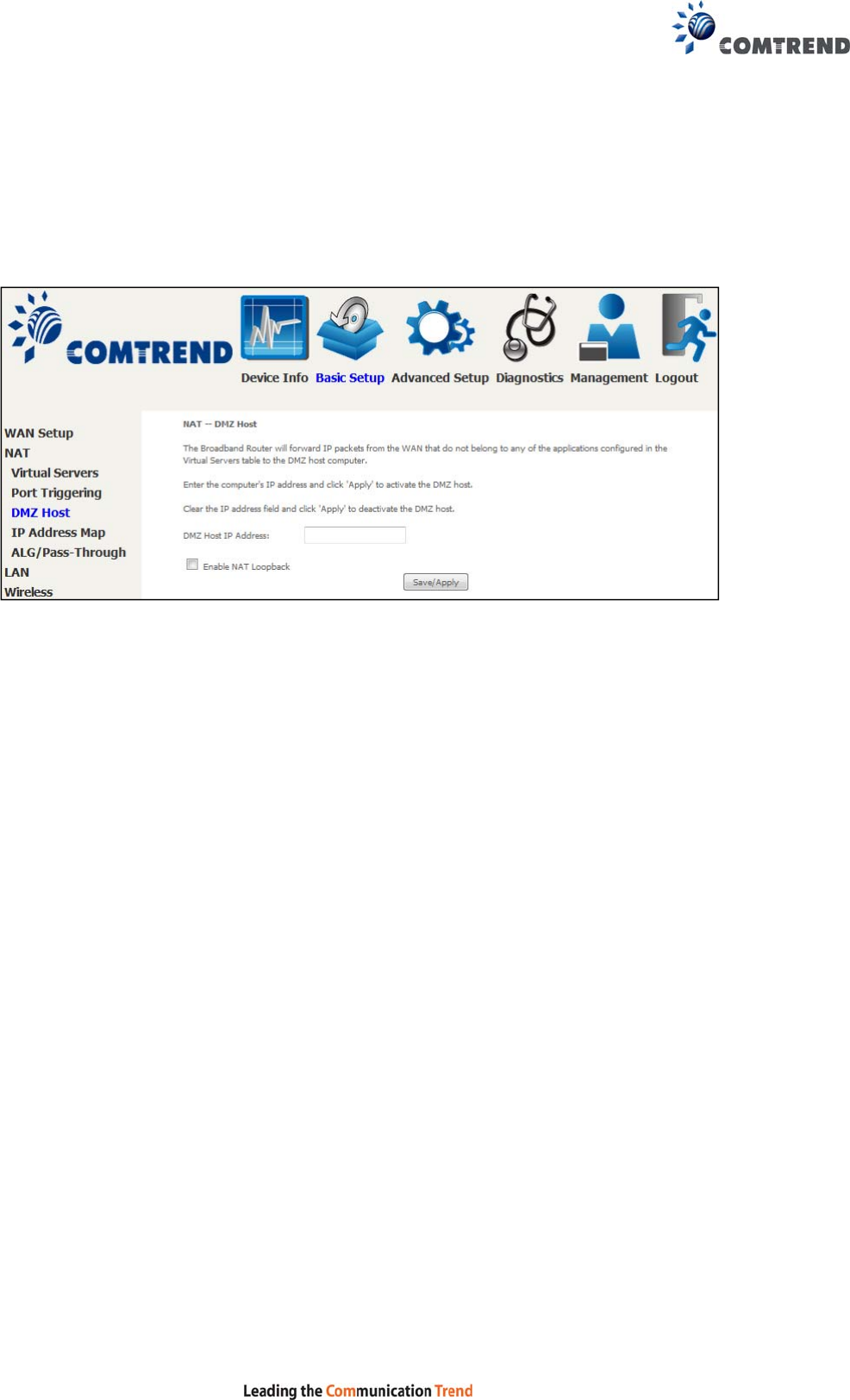
5.2.3 DMZ Host
The DSL router will forward IP packets from the WAN that do not belong to any of
the applications configured in the Virtual Servers table to the DMZ host computer.
To Activate the DMZ host, enter the DMZ host IP address and click Save/Apply.
To Deactivate the DMZ host, clear the IP address field and click Save/Apply.
Enable NAT Loopback allows PC on the LAN side to access servers in the LAN
network via the router’s WAN IP.
50
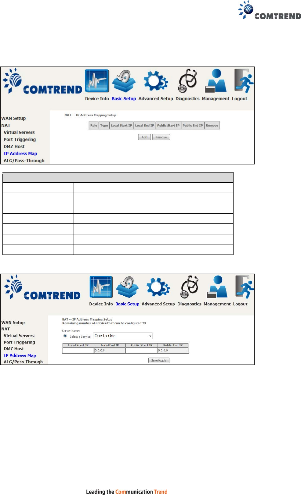
5.2.4 IP Address Map
Mapping Local IP (LAN IP) to some specified Public IP (WAN IP).
Field/Header Description
Rule The number of the rule
Type Mapping type from local to public
Local Start IP The beginning of the local IP
Local End IP The ending of the local IP
Public Start IP The beginning of the public IP
Public End IP The ending of the public IP
Remove Remove this rule
Click the Add button to display the following.
Select a Service, then click the Save/Apply button.
One to One: mapping one local IP to a specific public IP
Many to one: mapping a range of local IP to a specific public IP
Many to many(Overload): mapping a range of local IP to a different range of
public IP
Many to many(No Overload): mapping a range of local IP to a same range of
public IP
51
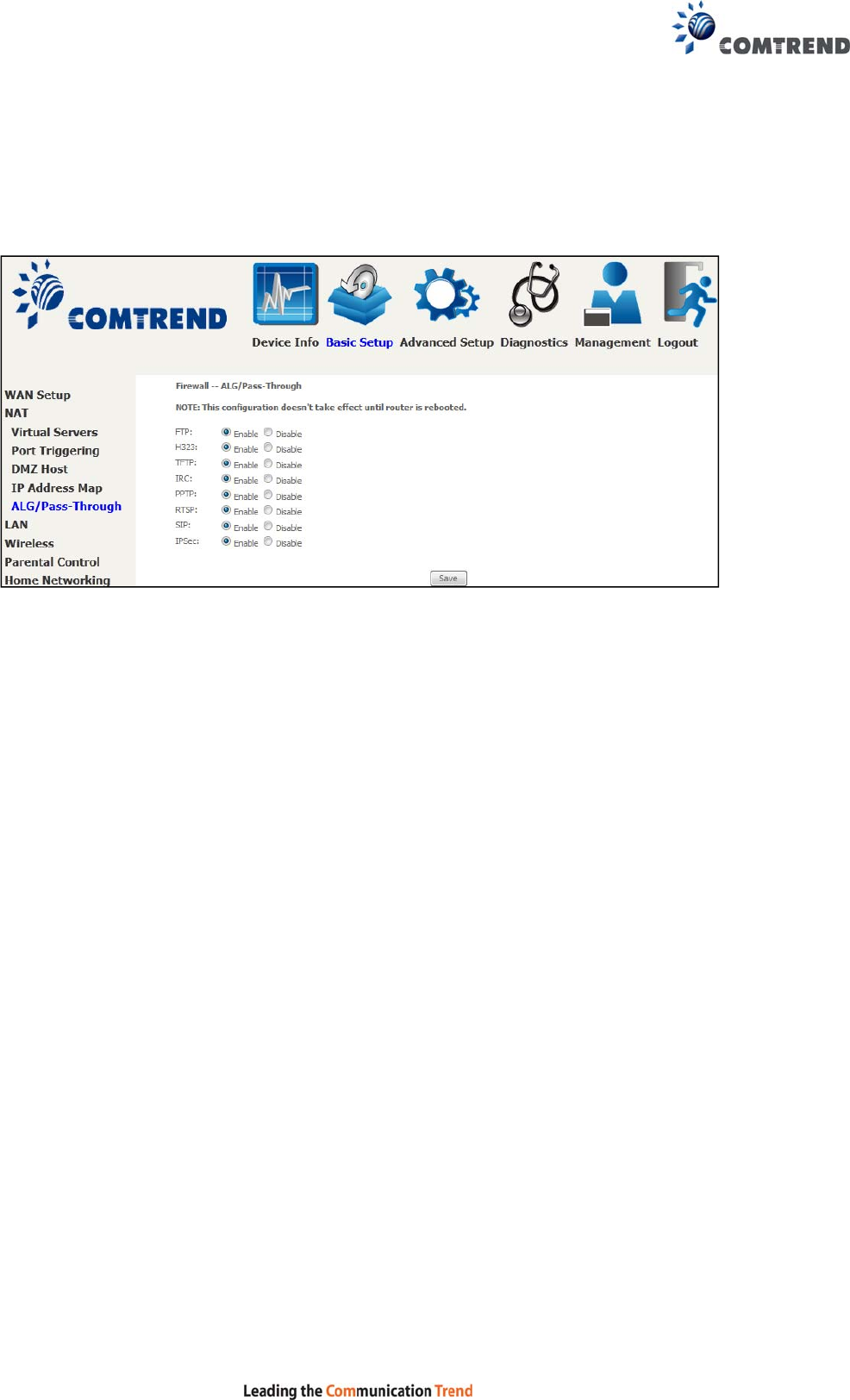
5.2.5 ALG/Pass-Through
Support ALG Pass-through for the listed protocols.
To allow/deny the corresponding ALG protocol, select Enable / Disable and then click
the Save button. After reboot, the protocol will be added/removed from the
system module.
52
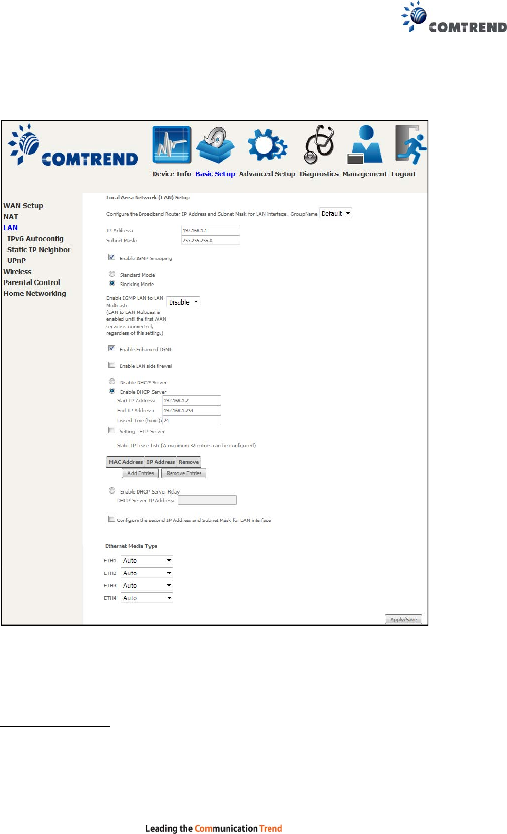
5.3 LAN
Configure the LAN interface settings and then click Apply/Save.
Consult the field descriptions below for more details.
GroupName: Select an Interface Group.
1st LAN INTERFACE
IP Address: Enter the IP address for the LAN port.
Subnet Mask: Enter the subnet mask for the LAN port.
53
Enable IGMP Snooping:
Standard Mode: In standard mode, multicast traffic will flood to all
bridge ports when no client subscribes to a multicast group
even if IGMP snooping is enabled.
Blocking Mode: In blocking mode, the multicast data traffic will be blocked and not
flood to all bridge ports when there are no client subscriptions to any
multicast group.
Enable IGMP LAN to LAN Multicast: Select Enable from the drop-down menu to
allow IGMP LAN to LAN Multicast forwarding
Enable Enhanced IGMP: Enable by ticking the checkbox . IGMP packets
between LAN ports will be blocked.
Enable LAN side firewall: Enable by ticking the checkbox .
DHCP Server: To enable DHCP, select Enable DHCP server and enter Start and
End IP addresses and the Leased Time. This setting configures the
router to automatically assign IP, default gateway and DNS server
addresses to every PC on your LAN.
Setting TFTP Server: Enable by ticking the checkbox . Then, input the TFTP
server address or an IP address.
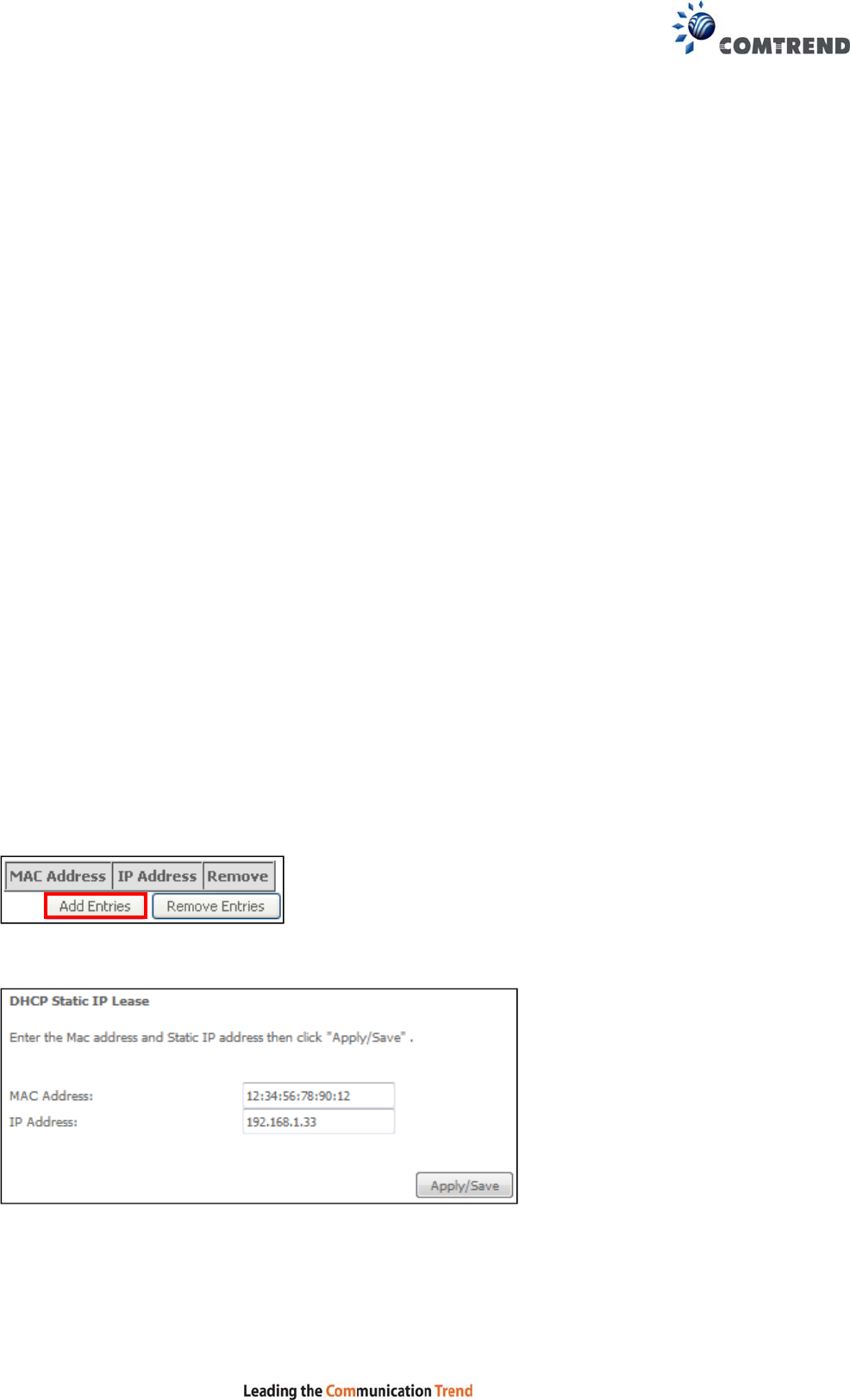
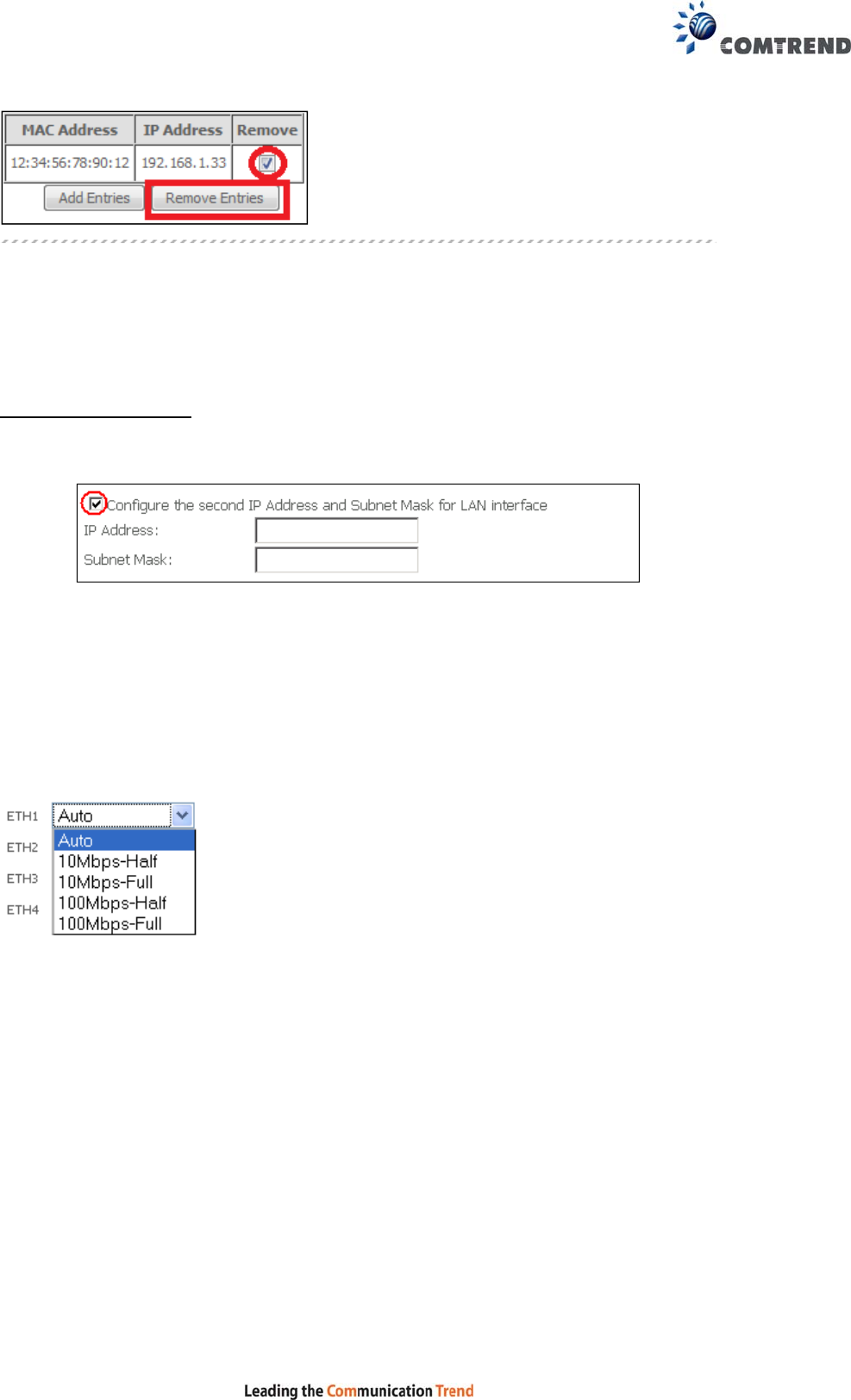
Static IP Lease List: A maximum of 32 entries can be configured.
To add an entry, enter MAC address and Static IP address and then click
Apply/Save.
To remove an entry, tick the corresponding checkbox in the Remove column and
then click the Remove Entries button, as shown below.
54
Select Enable DHCP Server Relay (not available if NAT enabled), and enter the
DHCP Server IP Address. This allows the Router to relay the DHCP packets to the
remote DHCP server. The remote DHCP server will provide the IP address.
2ND LAN INTERFACE
To configure a secondary IP address, tick the checkbox outlined (in RED) below.
IP Address: Enter the secondary IP address for the LAN port.
Subnet Mask: Enter the secondary subnet mask for the LAN port.
Ethernet Media Type:
Configure auto negotiation, or enforce selected speed and duplex mode for the
Ethernet ports.
55
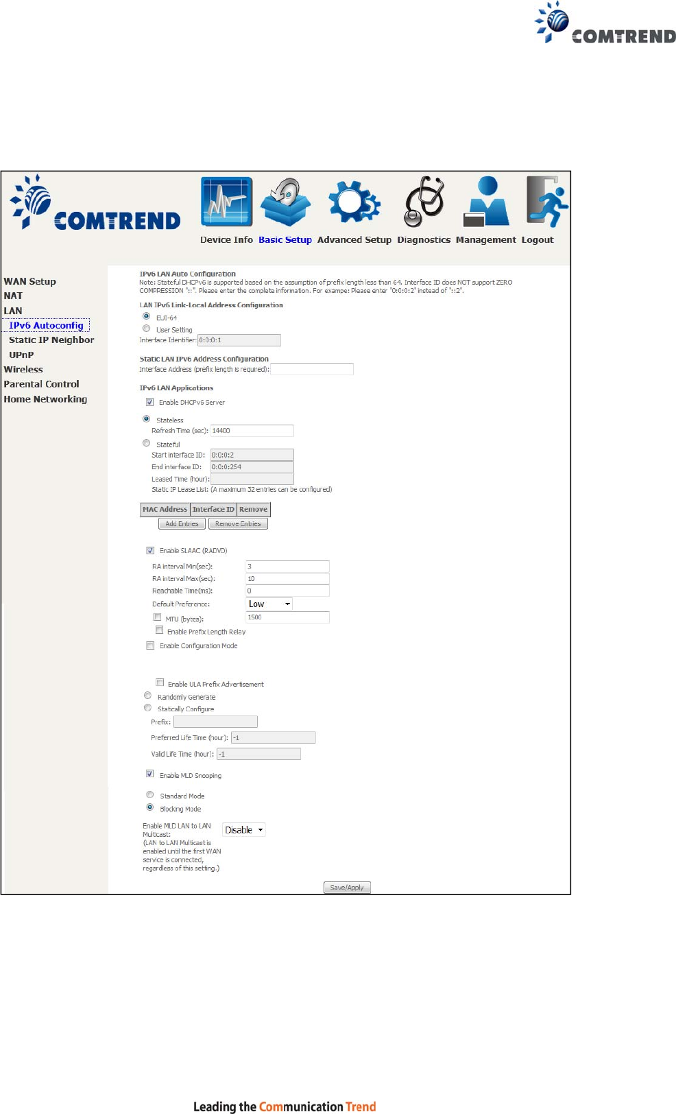
5.3.1 LAN IPv6 Autoconfig
Configure the LAN interface settings and then click Save/Apply.
Consult the field descriptions below for more details.
56
LAN IPv6 Link-Local Address Configuration
Heading Description
EUI-64 Use EUI-64 algorithm to calculate link-local address from MAC
address
User Setting Use the Interface Identifier field to define a link-local address
Static LAN IPv6 Address Configuration
Heading Description
Interface Address
(prefix length is
required):
Configure static LAN IPv6 address and subnet prefix
length
IPv6 LAN Applications
Heading Description
Stateless Use stateless configuration
Refresh Time (sec): The information refresh time option specifies how long a
client should wait before refreshing information retrieved
from DHCPv6
Stateful Use stateful configuration
Start interface ID: Start of interface ID to be assigned to dhcpv6 client
End interface ID: End of interface ID to be assigned to dhcpv6 client
Leased Time (hour): Lease time for dhcpv6 client to use the assigned IP address
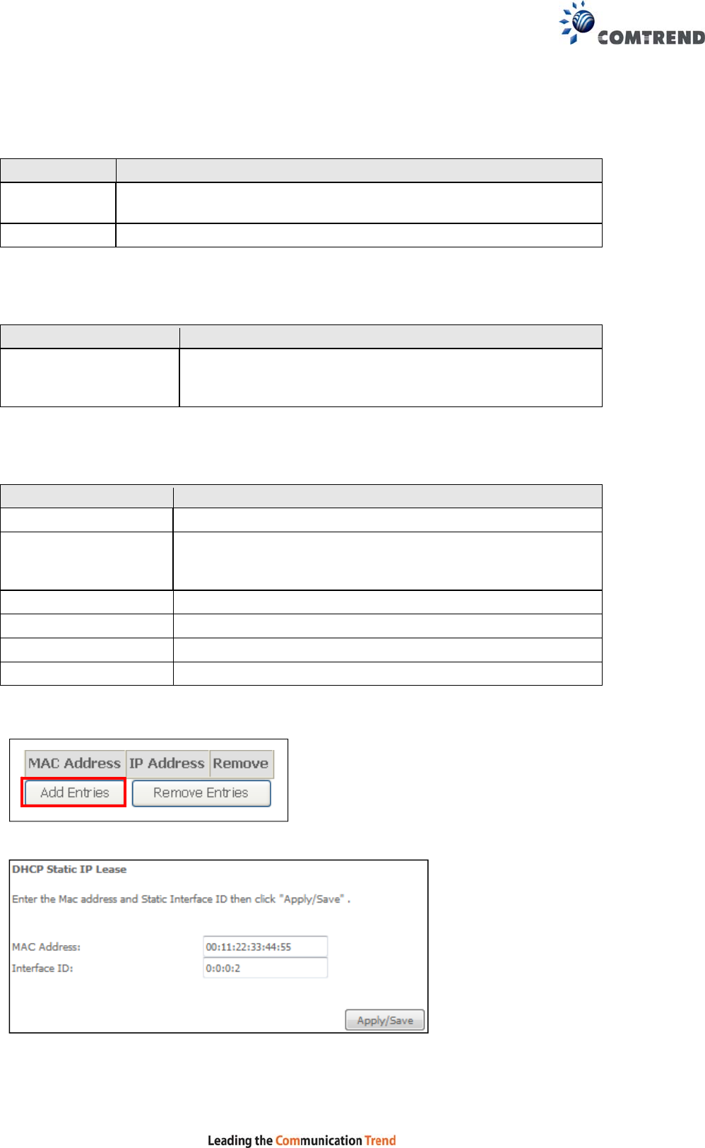
Static IP Lease List: A maximum of 32 entries can be configured.
To add an entry, enter MAC address and Interface ID and then click Apply/Save.
57
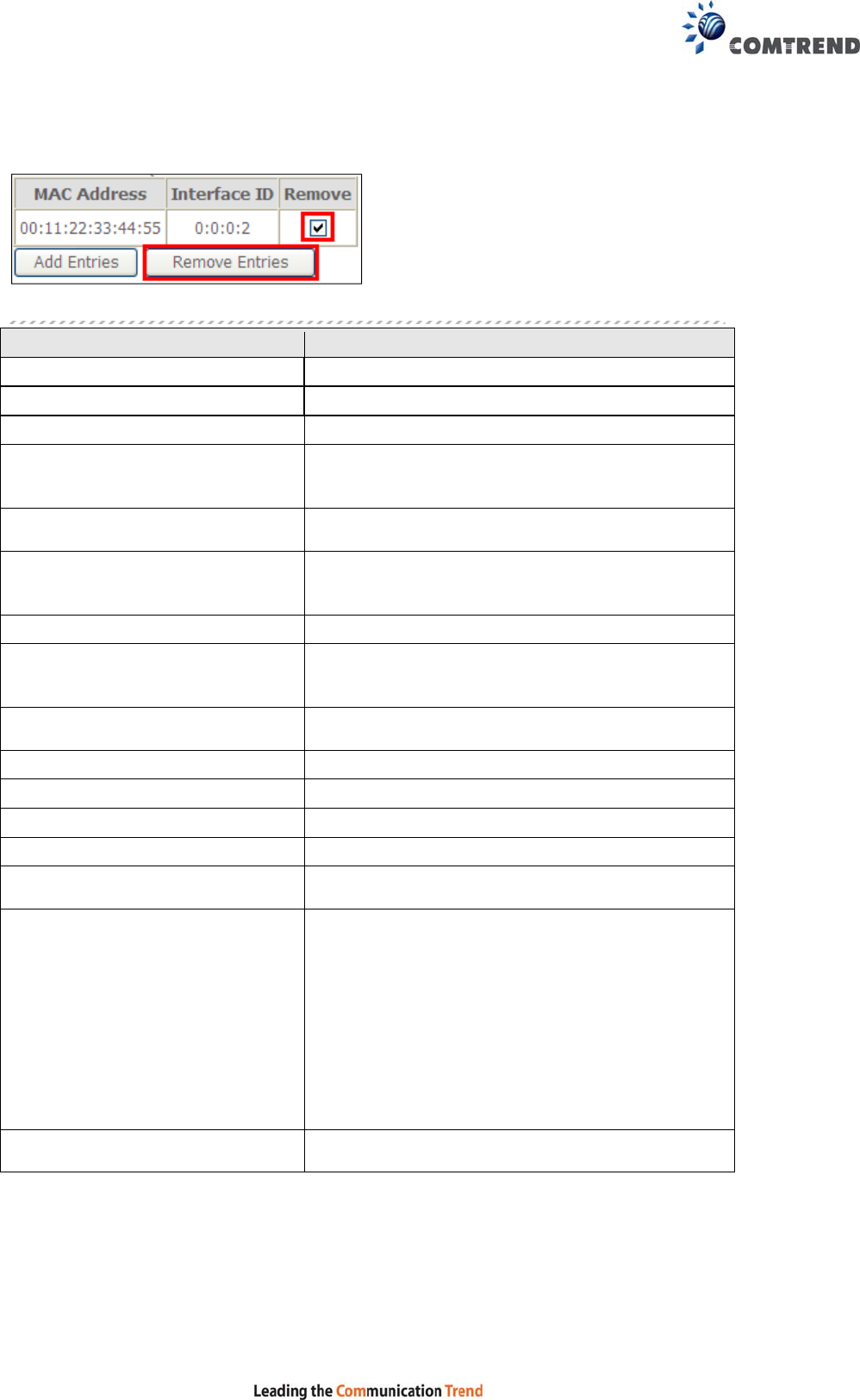
To remove an entry, tick the corresponding checkbox in the Remove column and
then click the Remove Entries button, as shown below.
Heading Description
Enable RADVD Enable use of router advertisement daemon
RA interval Min(sec): Minimum time to send router advertisement
RA interval Max(sec): Maximum time to send router advertisement
Reachable Time(ms): The time, in milliseconds that a neighbor is
reachable after receiving reachability
confirmation
Default Preference: Preference level associated with the default
router
MTU (bytes): MTU value used in router advertisement
messages to insure that all nodes on a link use
the same MTU value
Enable Prefix Length Relay Use prefix length receive from WAN interface
Enable Configuration Mode Manually configure prefix, prefix length,
preferred lifetime and valid lifetime used in
router advertisement
Enable ULA Prefix Advertisement
Allow RADVD to advertise Unique Local Address
Prefix
Randomly Generate Use a Randomly Generated Prefix
Statically Configure Prefix Specify the prefix to be used
Preferred Life Time (hour) The preferred life time for this prefix
Valid Life Time (hour) The valid life time for this prefix
Enable MLD Snooping Enable/disable IPv6 multicast forward to LAN
ports
Standard Mode
Blocking Mode In standard mode, IPv6 multicast traffic will
flood to all bridge ports when no client
subscribes to a multicast group even if MLD
snooping is enabled
In blocking mode, IPv6 multicast data traffic will
be blocked and not flood to all bridge ports when
there are no client subscriptions to any
multicast group
Enable MLD LAN
To LAN Multicast Enable/disable IPv6 multicast between LAN
ports
58
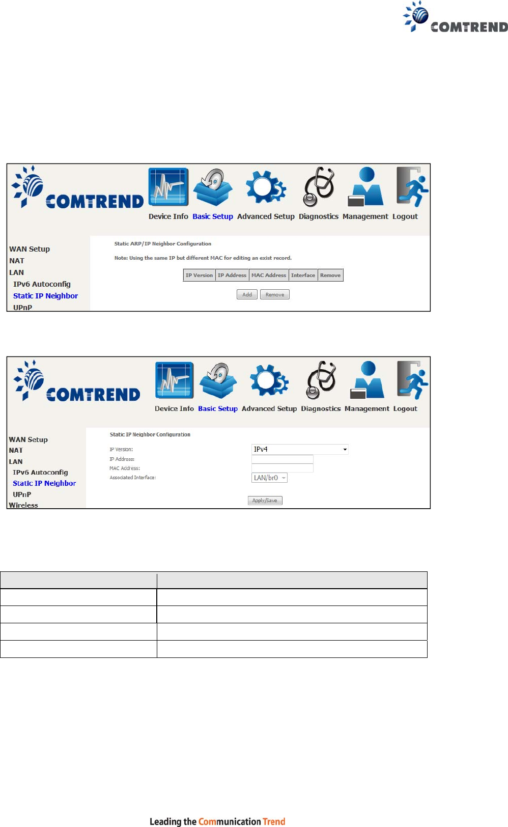
5.3.2 Static IP Neighbor
This page is used to configure a static IPv4 or IPv6 Neighbor entry. Static ARP
entries will be created for these neighbor devices.
Click the Add button to display the following.
Click Apply/Save to apply and save the settings.
Heading Description
IP Version The IP version used for the neighbor device
IP Address Define the IP Address for the neighbor device
MAC Address The MAC Address of the neighbor device
Associated Interface The interface where the neighbor device is located
59
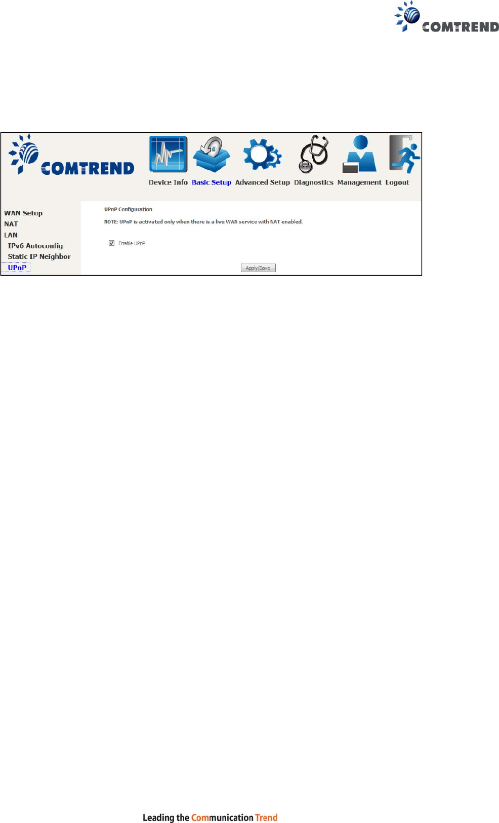
5.3.3 UPnP
Select the checkbox provided and click Apply/Save to enable UPnP protocol.
60
5.4 Wireless
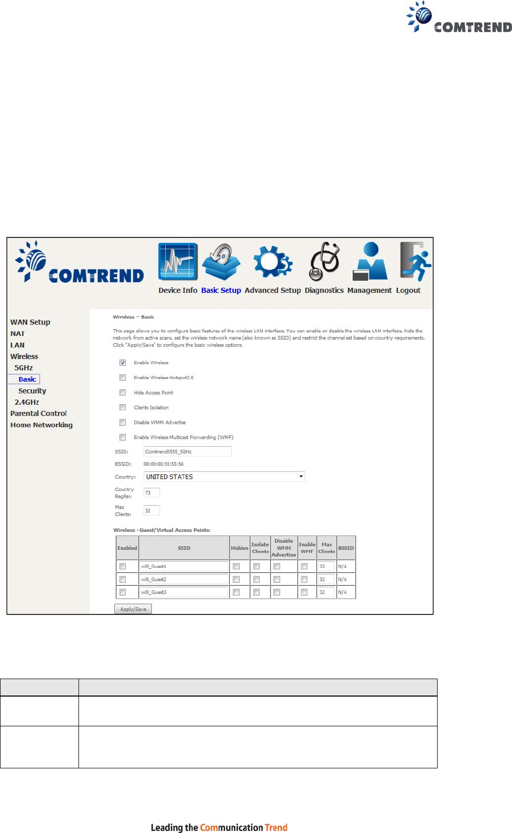
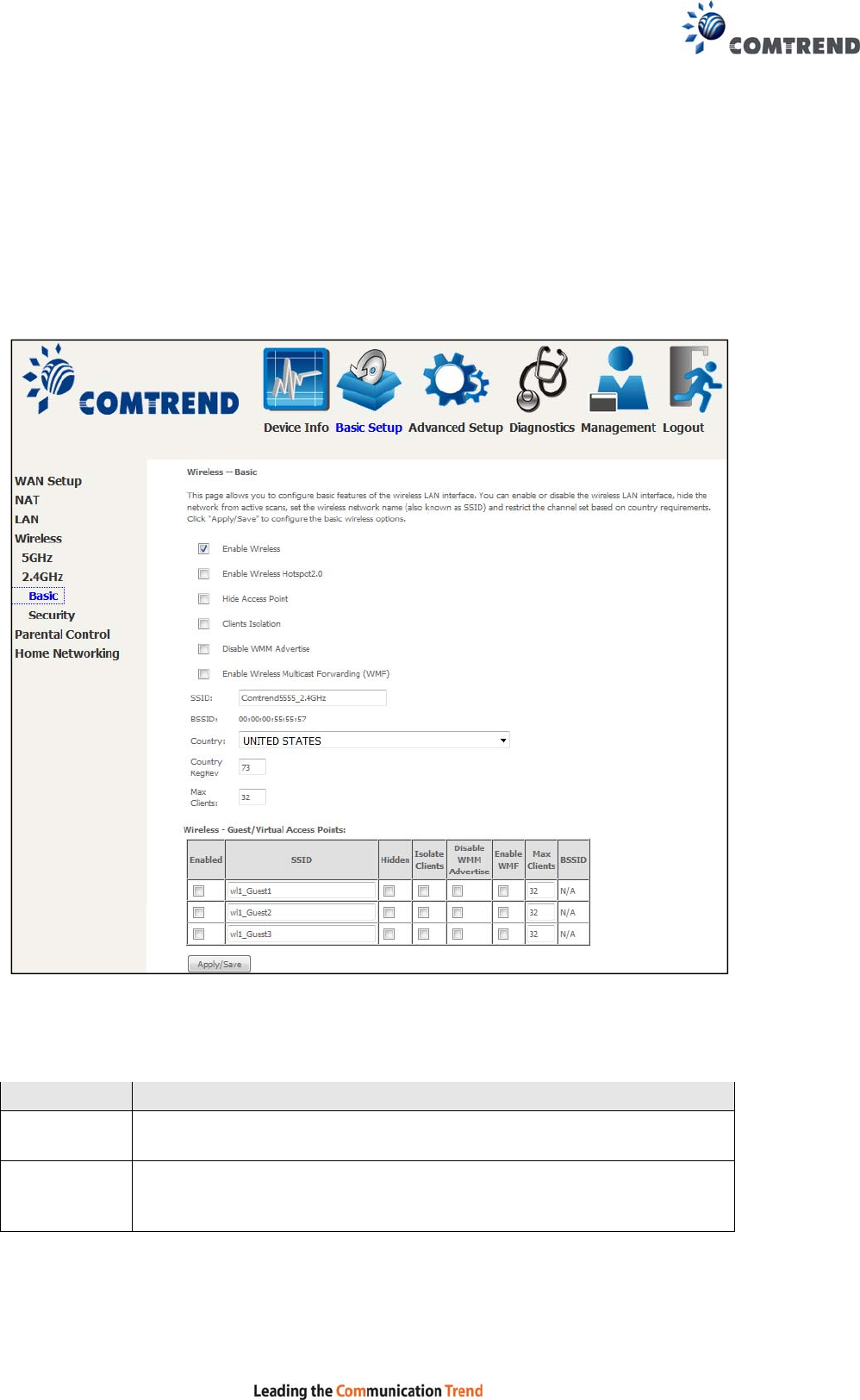
5.4.1 Basic 5GHz
The Basic option allows you to configure basic features of the wireless LAN interface.
Among other things, you can enable or disable the wireless LAN interface, hide the
network from active scans, set the wireless network name (also known as SSID)
and configure the channel setting for the wireless LAN interface.
Click the Apply/Save button to apply the selected wireless options.
Consult the table below for descriptions of these options.
Option Description
Enable
Wireless A checkbox that enables or disables the wireless LAN interface.
When selected, a set of basic wireless options will appear.
Enable
Wireless
Hotspot2.0
Enable Wireless Hotspot 2.0 (Wi-Fi Certified Passpoint) on the
wireless interface.

61
Option Description
Hide Access
Point Select Hide Access Point to protect the access point from detection
by wireless active scans. If the access point is hidden, it will not be
listed or listed with empty SSID in the scan result of wireless
stations. To connect a client to a hidden access point, the station
must add the access point manually to its wireless configuration.
Clients
Isolation When enabled, it prevents client PCs from seeing one another in My
Network Places or Network Neighborhood. Also, prevents one
wireless client communicating with another wireless client.
Disable WMM
Advertise
Stops the router from ‘advertising’ its Wireless Multimedia (WMM)
functionality, which provides basic quality of service for
time-sensitive applications (e.g. VoIP, Video).
Enable
Wireless
Multicast
Forwarding
Select the checkbox to enable this function.
SSID
[1-32
characters]
Sets the wireless network name. SSID stands for Service Set
Identifier. All stations must be configured with the correct SSID to
access the WLAN. If the SSID does not match, that user will not be
granted access.
BSSID The BSSID is a 48-bit identity used to identify a particular BSS (Basic
Service Set) within an area. In Infrastructure BSS networks, the
BSSID is the MAC (Media Access Control) address of the AP (Access
Point); and in Independent BSS or ad hoc networks, the BSSID is
generated randomly.
Country A drop-down menu that permits worldwide and specific national
settings. Local regulations limit channel range:
US= worldwide, Japan=1-14, Jordan= 10-13, Israel= 1-13
Country
RegRev Wireless country code for transmit power limit.
Max Clients The maximum number of clients that can access the router.
Wireless -
Guest /
Virtual
Access
Points
This router supports multiple SSIDs called Guest SSIDs or Virtual
Access Points. To enable one or more Guest SSIDs select the
checkboxes in the Enabled column. To hide a Guest SSID, select
its checkbox in the Hidden column.
Do the same for Isolate Clients and Disable WMM Advertise.
For a description of these two functions, see the previous entries for
“Clients Isolation” and “Disable WMM Advertise”. Similarly, for
Enable WMF, Max Clients and BSSID, consult the matching
entries in this table.
NOTE: Remote wireless hosts cannot scan Guest SSIDs.
62
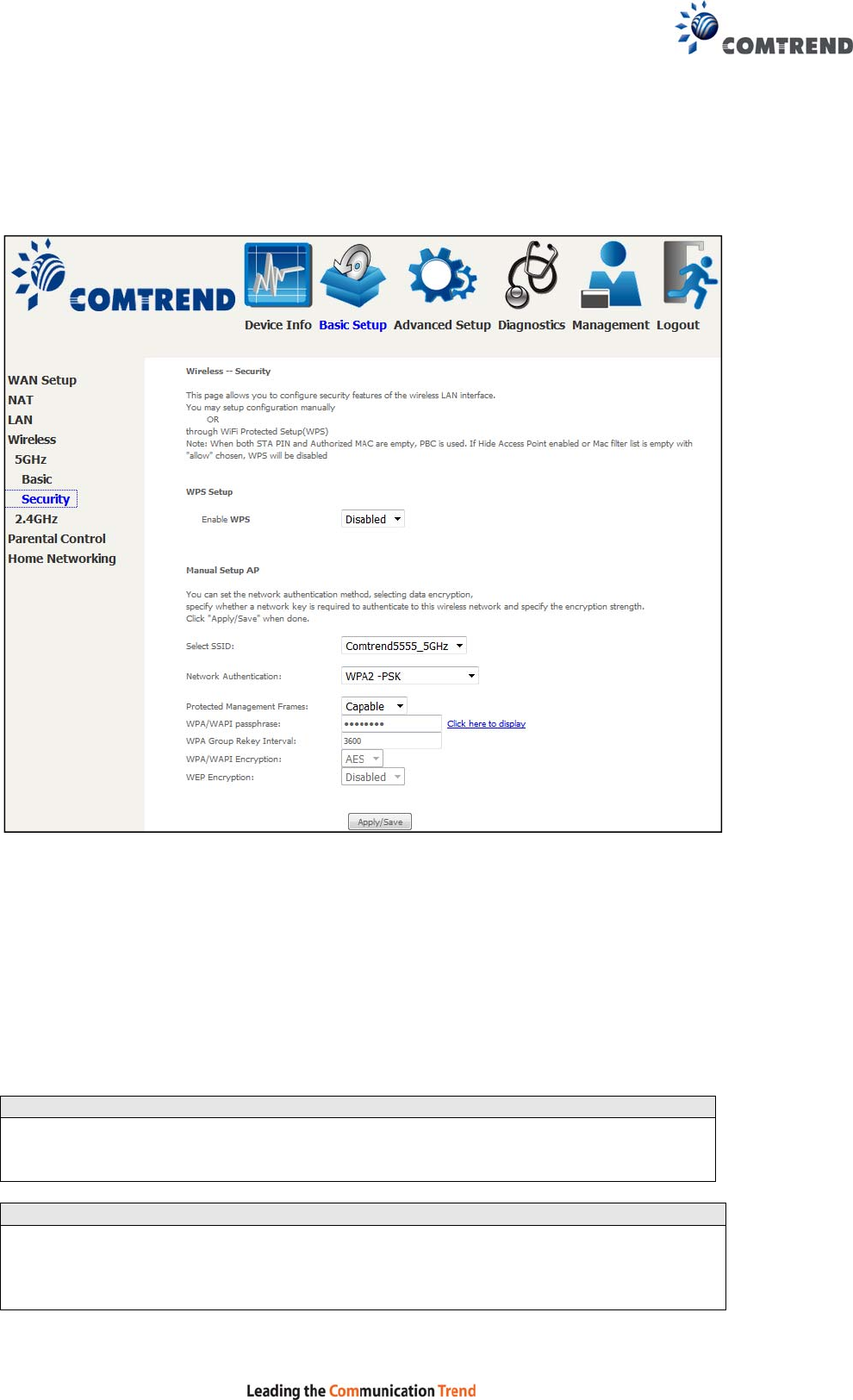
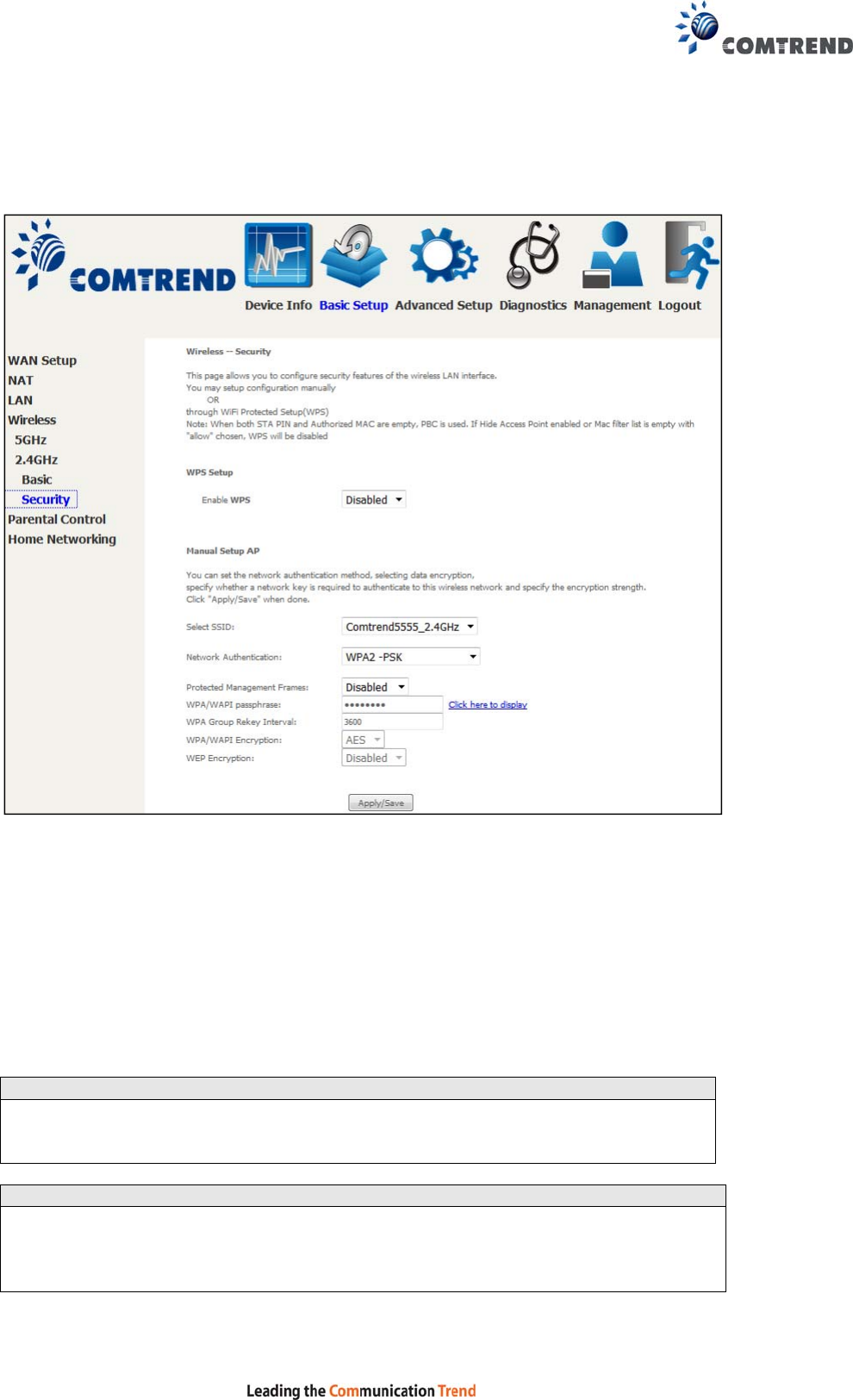
5.4.2 Security 5GHz
The following screen appears when Wireless Security is selected. The options shown
here allow you to configure security features of the wireless LAN interface.
Click Apply/Save to implement new configuration settings.
Please see 6.12.3 for WPS setup instructions.
WIRELESS SECURITY
Setup requires that the user configure these settings using the Web User Interface
(see the table below).
Select SSID
Select the wireless network name from the drop-down menu. SSID stands for
Service Set Identifier. All stations must be configured with the correct SSID to
access the WLAN. If the SSID does not match, that client will not be granted access.
Network Authentication
This option specifies whether a network key is used for authentication to the wireless
network. If network authentication is set to Open, then no authentication is
provided. Despite this, the identity of the client is still verified.
63
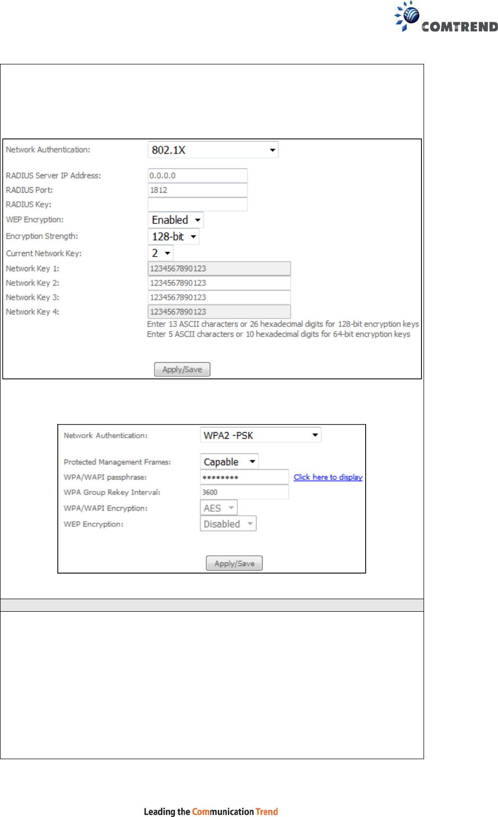
Each authentication type has its own settings. For example, selecting 802.1X
authentication will reveal the RADIUS Server IP address, Port and Key fields. WEP
Encryption will also be enabled as shown below.
The settings for WPA2-PSK authentication are shown next.
WEP Encryption
This option specifies whether data sent over the network is encrypted. The same
network key is used for data encryption and network authentication. Four network
keys can be defined although only one can be used at any one time. Use the Current
Network Key list box to select the appropriate network key.
Security options include authentication and encryption services based on the wired
equivalent privacy (WEP) algorithm. WEP is a set of security services used to
protect 802.11 networks from unauthorized access, such as eavesdropping; in this
case, the capture of wireless network traffic.
When data encryption is enabled, secret shared encryption keys are generated and
used by the source station and the destination station to alter frame bits, thus
avoiding disclosure to eavesdroppers.

64
Under shared key authentication, each wireless station is assumed to have received
a secret shared key over a secure channel that is independent from the 802.11
wireless network communications channel.
Encryption Strength
This drop-down list box will display when WEP Encryption is enabled. The key
strength is proportional to the number of binary bits comprising the key. This
means that keys with a greater number of bits have a greater degree of security and
are considerably more difficult to crack. Encryption strength can be set to either
64-bit or 128-bit. A 64-bit key is equivalent to 5 ASCII characters or 10
hexadecimal numbers. A 128-bit key contains 13 ASCII characters or 26
hexadecimal numbers. Each key contains a 24-bit header (an initiation vector)
which enables parallel decoding of multiple streams of encrypted data.
Please see 6.12 for MAC Filter, Wireless Bridge and Advanced Wireless features.
65
5.4.3 Basic 2.4GHz
The Basic option allows you to configure basic features of the wireless LAN interface.
Among other things, you can enable or disable the wireless LAN interface, hide the
network from active scans, set the wireless network name (also known as SSID)
and restrict the channel set based on country requirements.
Click the Apply/Save button to apply the selected wireless options.
Consult the table below for descriptions of these options.
Option Description
Enable
Wireless A checkbox that enables or disables the wireless LAN interface.
When selected, a set of basic wireless options will appear.
Enable
Wireless
Hotspot2.0
Enable Wireless Hotspot 2.0 (Wi-Fi Certified Passpoint) on the
wireless interface.

66
Option Description
Hide Access
Point Select Hide Access Point to protect the access point from detection
by wireless active scans. If the access point is hidden, it will not be
listed or listed with empty SSID in the scan result of wireless
stations. To connect a client to a hidden access point, the station
must add the access point manually to its wireless configuration.
Clients
Isolation When enabled, it prevents client PCs from seeing one another in My
Network Places or Network Neighborhood. Also, prevents one
wireless client communicating with another wireless client.
Disable WMM
Advertise
Stops the router from ‘advertising’ its Wireless Multimedia (WMM)
functionality, which provides basic quality of service for
time-sensitive applications (e.g. VoIP, Video).
Enable
Wireless
Multicast
Forwarding
Select the checkbox to enable this function.
SSID
[1-32
characters]
Sets the wireless network name. SSID stands for Service Set
Identifier. All stations must be configured with the correct SSID to
access the WLAN. If the SSID does not match, that user will not be
granted access.
BSSID The BSSID is a 48-bit identity used to identify a particular BSS (Basic
Service Set) within an area. In Infrastructure BSS networks, the
BSSID is the MAC (Media Access Control) address of the AP (Access
Point); and in Independent BSS or ad hoc networks, the BSSID is
generated randomly.
Country A drop-down menu that permits worldwide and specific national
settings. Local regulations limit channel range:
US= worldwide, Japan=1-14, Jordan= 10-13, Israel= 1-13
Country
RegRev Wireless country code for transmit power limit.
Max Clients The maximum number of clients that can access the router.
Wireless -
Guest /
Virtual
Access
Points
This router supports multiple SSIDs called Guest SSIDs or Virtual
Access Points. To enable one or more Guest SSIDs select the
checkboxes in the Enabled column. To hide a Guest SSID, select
its checkbox in the Hidden column.
Do the same for Isolate Clients and Disable WMM Advertise.
For a description of these two functions, see the previous entries for
“Clients Isolation” and “Disable WMM Advertise”. Similarly, for
Enable WMF, Max Clients and BSSID, consult the matching
entries in this table.
NOTE: Remote wireless hosts cannot scan Guest SSIDs.
67
5.4.4 Security 2.4GHz
The following screen appears when Wireless Security is selected. The options shown
here allow you to configure security features of the wireless LAN interface.
Click Apply/Save to implement new configuration settings.
Please see 6.12.9 for WPS setup instructions.
WIRELESS SECURITY
Setup requires that the user configure these settings using the Web User Interface
(see the table below).
Select SSID
Select the wireless network name from the drop-down menu. SSID stands for
Service Set Identifier. All stations must be configured with the correct SSID to
access the WLAN. If the SSID does not match, that client will not be granted access.
Network Authentication
This option specifies whether a network key is used for authentication to the wireless
network. If network authentication is set to Open, then no authentication is
provided. Despite this, the identity of the client is still verified.
68
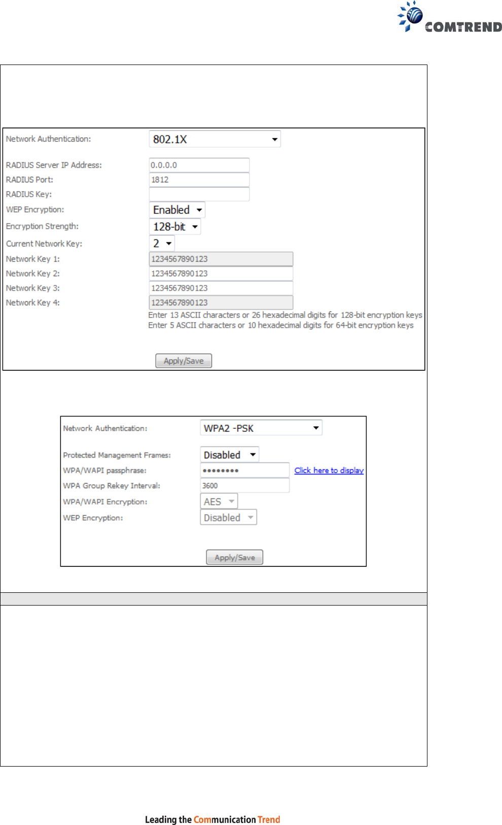
Each authentication type has its own settings. For example, selecting 802.1X
authentication will reveal the RADIUS Server IP address, Port and Key fields. WEP
Encryption will also be enabled as shown below.
The settings for WPA2-PSK authentication are shown next.
WEP Encryption
This option specifies whether data sent over the network is encrypted. The same
network key is used for data encryption and network authentication. Four network
keys can be defined although only one can be used at any one time. Use the Current
Network Key list box to select the appropriate network key.
Security options include authentication and encryption services based on the wired
equivalent privacy (WEP) algorithm. WEP is a set of security services used to
protect 802.11 networks from unauthorized access, such as eavesdropping; in this
case, the capture of wireless network traffic.
When data encryption is enabled, secret shared encryption keys are generated and
used by the source station and the destination station to alter frame bits, thus
avoiding disclosure to eavesdroppers.

69
Under shared key authentication, each wireless station is assumed to have received
a secret shared key over a secure channel that is independent from the 802.11
wireless network communications channel.
Encryption Strength
This drop-down list box will display when WEP Encryption is enabled. The key
strength is proportional to the number of binary bits comprising the key. This
means that keys with a greater number of bits have a greater degree of security and
are considerably more difficult to crack. Encryption strength can be set to either
64-bit or 128-bit. A 64-bit key is equivalent to 5 ASCII characters or 10
hexadecimal numbers. A 128-bit key contains 13 ASCII characters or 26
hexadecimal numbers. Each key contains a 24-bit header (an initiation vector)
which enables parallel decoding of multiple streams of encrypted data.
Please see 6.12 for MAC Filter, Wireless Bridge and Advanced Wireless features.
70
5.5 Parental Control
This selection provides WAN access control functionality.
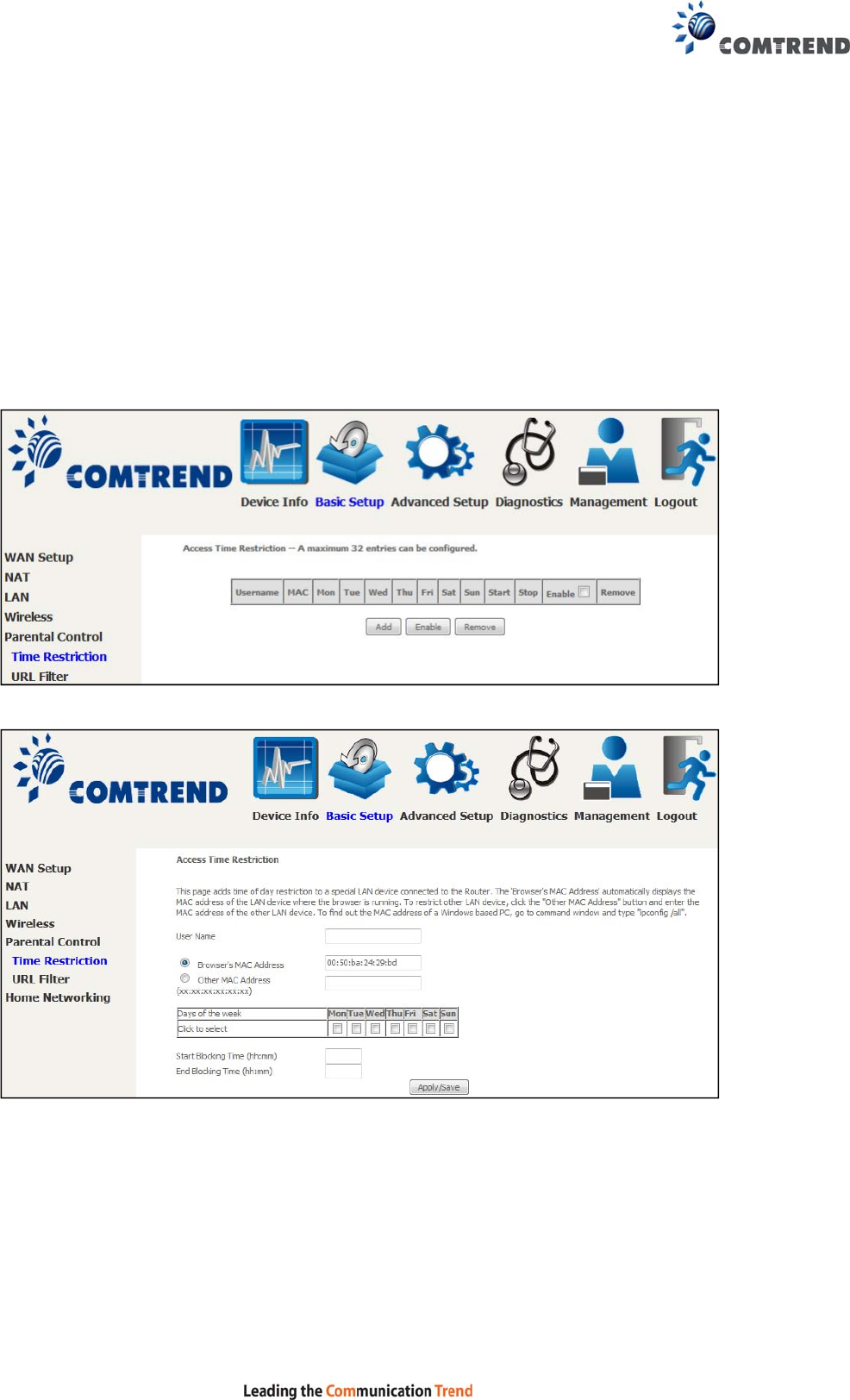
5.5.1 Time Restriction
This feature restricts access from a LAN device to an outside network through the
device on selected days at certain times. Make sure to activate the Internet Time
server synchronization as described in section 8.5 Internet Time, so that the
scheduled times match your local time.
Clicking on the checkbox in the Enable field allows the user to select all / none
entries for Enabling/Disabling.
Click Add to display the following screen.
See below for field descriptions. Click Apply/Save to add a time restriction.
User Name: A user-defined label for this restriction.
Browser's MAC Address: MAC address of the PC running the browser.
Other MAC Address: MAC address of another LAN device.
Days of the Week: The days the restrictions apply.
Start Blocking Time: The time the restrictions start.
End Blocking Time: The time the restrictions end.
71
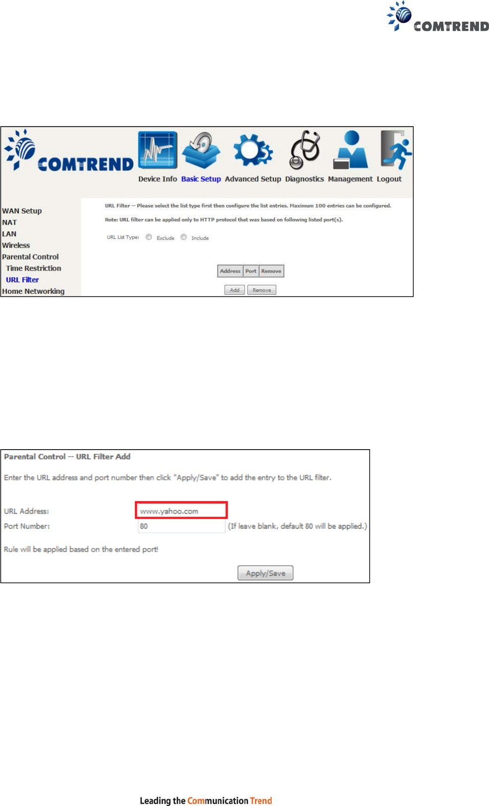
5.5.2 URL Filter
This screen allows for the creation of a filter rule for access rights to websites based
on their URL address and port number.
Select URL List Type: Exclude or Include.
Tick the Exclude radio button to deny access to the websites listed.
Tick the Include radio button to restrict access to only those listed websites.
Then click Add to display the following screen.
Enter the URL address and port number then click Apply/Save to add the entry to
the URL filter. URL Addresses begin with “www”, as shown in this example.
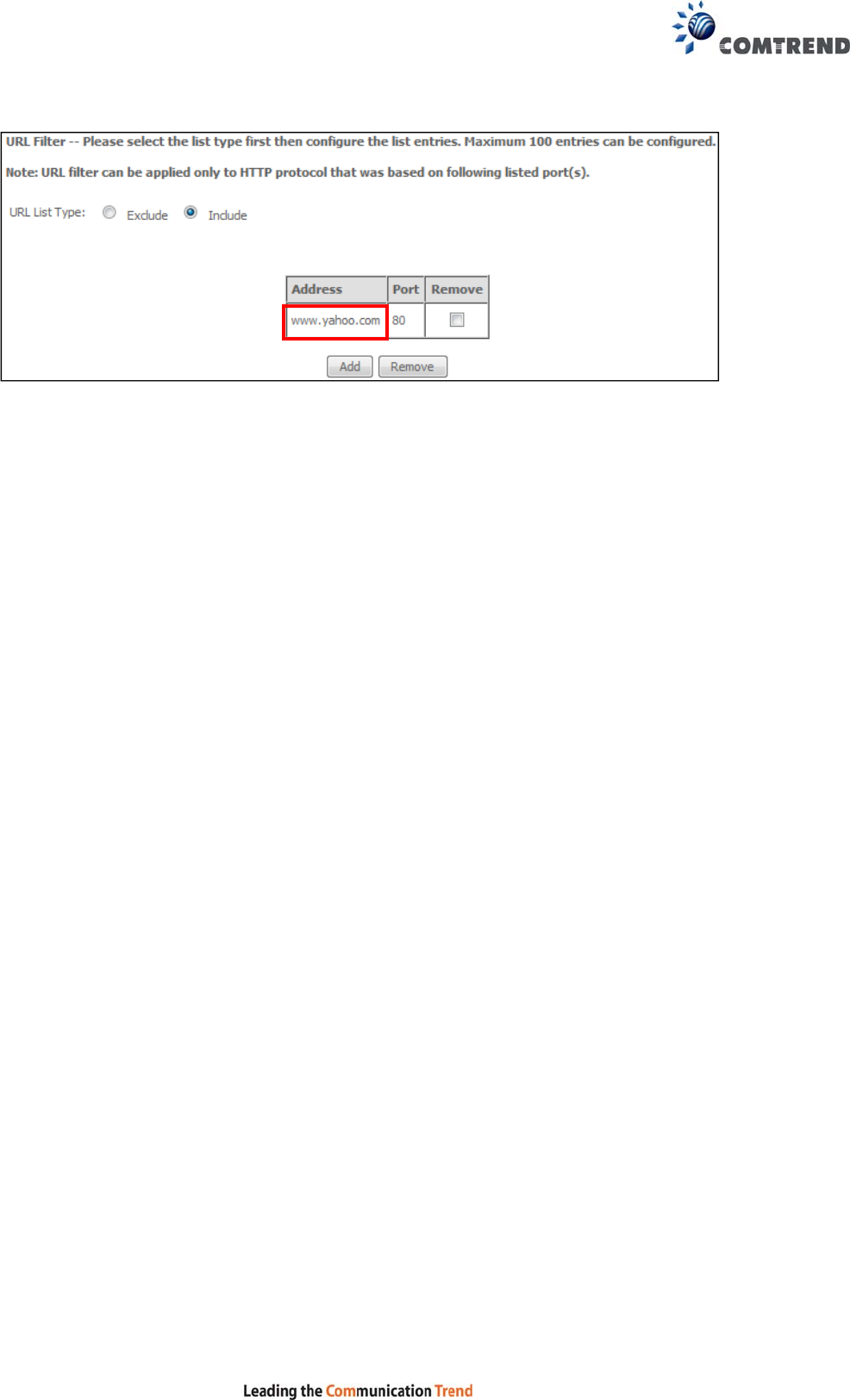
72
A maximum of 100 entries can be added to the URL Filter list.
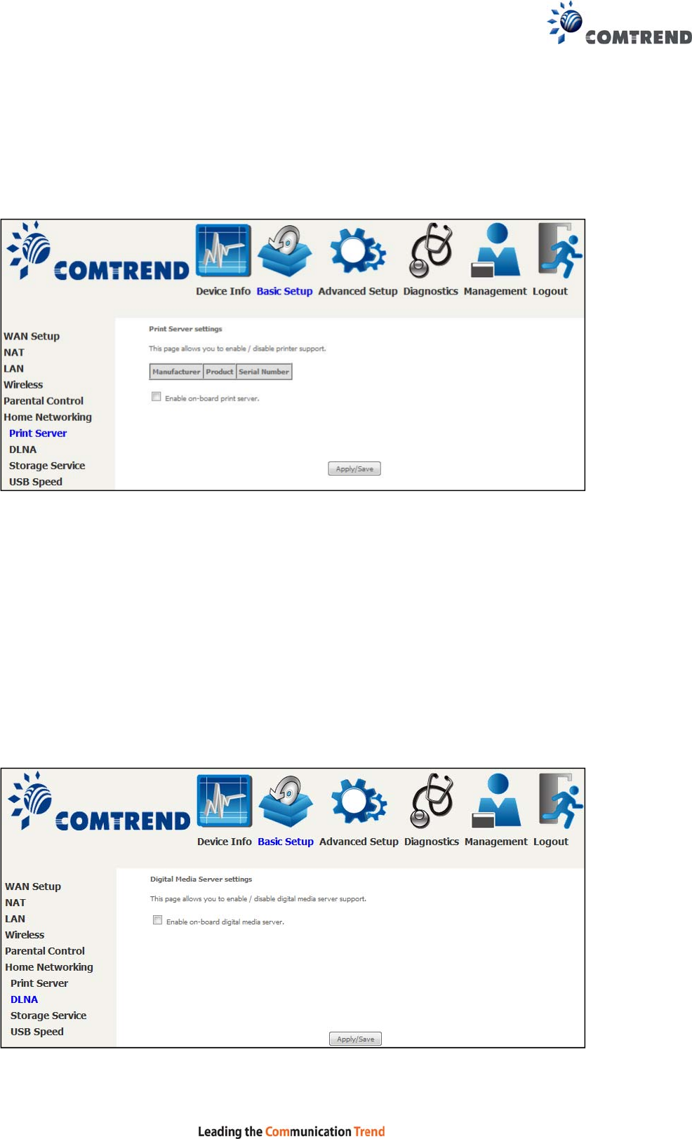
73
5.6 Home networking
5.6.1 Print Server
This page allows you to enable or disable printer support.
Please reference Appendix E to see the procedure for enabling the Printer Server.
5.6.2 DLNA
Enabling DLNA allows users to share digital media, like pictures, music and video, to
other LAN devices from the digital media server.
Insert the USB drive into the USB host port on the back of the router.
Click Enable on-board digital media server, a dropdown list of directories found on
the USB driver will be available for selection. Select media path from the
drop-down list or manually modify the media library path and click Apply/Save to
enable the DLNA media server.
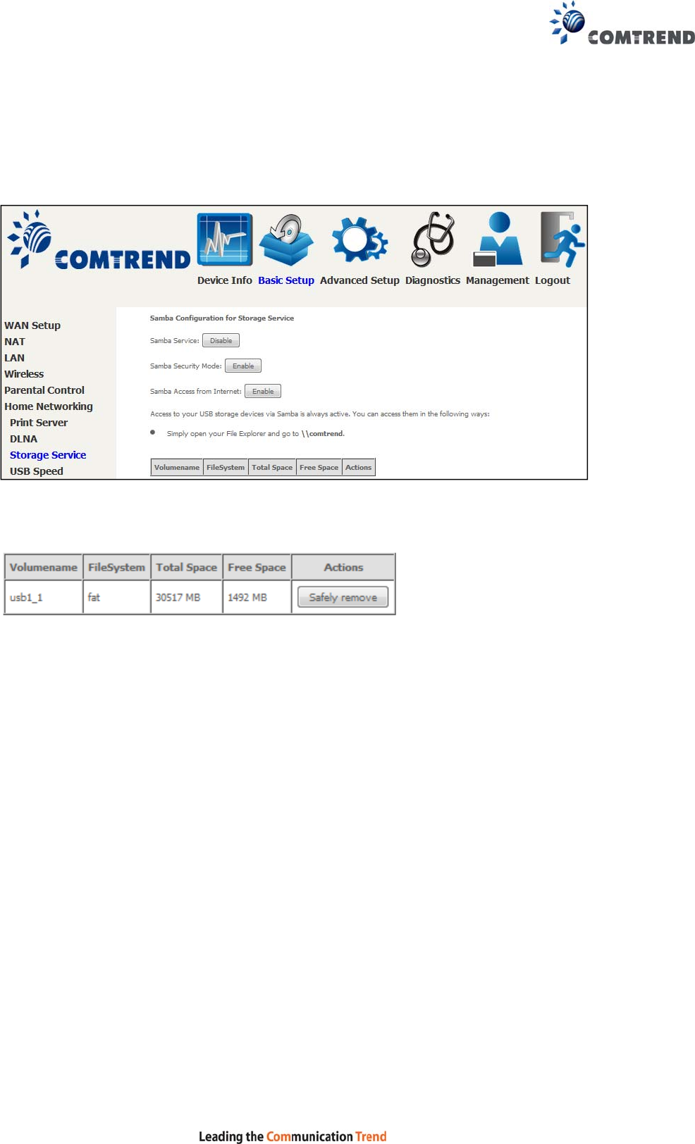
74
5.6.3 Storage Service
Enabling Samba service allows the user to share files on the storage
device. Different levels of user access can be configured after samba security mode
is enabled. This page also displays storage devices attached to the USB host.
Display after storage device attached (for your reference).
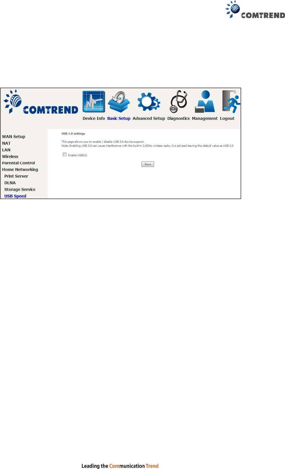
75
5.6.4 USB Speed
This page allows you to enable / disable USB 3.0 device support.
Note: Enabling USB 3.0 can cause interference with the built-in 2.4GHz wireless
radio. It is advised leaving the default value as USB 2.0
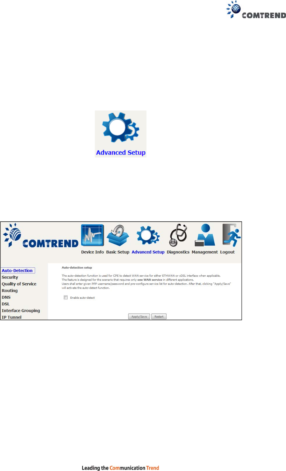
76
Chapter 6 Advanced Setup
You can reach this page by clicking on the following icon located at the top of the
screen.
6.1 Auto-detection setup
The auto-detection function is used for CPE to detect WAN service for either
ETHWAN or xDSL interfaces. The feature is designed for the scenario that requires
only one WAN service in different applications.
The Auto Detection page simply provides a checkbox allowing users to enable or
disable the feature. Check the checkbox to display the following configuration
options.
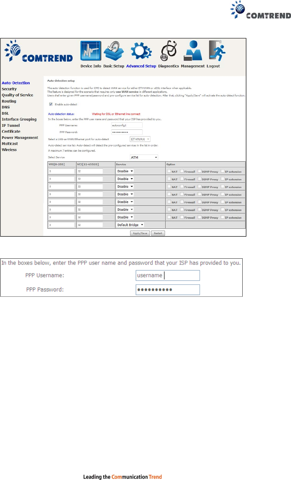
77
Enter the PPP username/password given by your service provider for PPP service
detection.
Select a LAN-as-WAN Ethernet port for auto-detect:
Select the Ethernet Port that will be used as ETH WAN during auto-detection. For
models with ETH WAN port, only ETH WAN port is available to be used as WAN port.
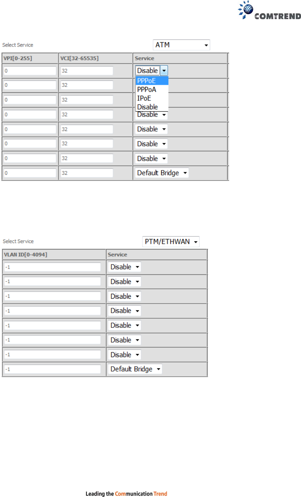
78
WAN services list for ATM mode: A maximum of 7 WAN services with
corresponding PVC are required to be configured for ADSL ATM mode. The services
will be detected in order. Users can modify the 7 pre-configured services and select
disable to ignore any of those services to meet their own requirement and also
reduce the detection cycle.
WAN services list for PTM mode: A maximum of 7 WAN services with
corresponding VLAN ID (-1 indicates no VLAN ID is required for the service) are
required to be configured for ADSL/VDSL PTM mode and ETHWAN. The services will
be detected in order. Users can modify the 7 pre-configured services and select
disable to ignore any of the services to meet their own requirements and also
reduce the detection cycle.
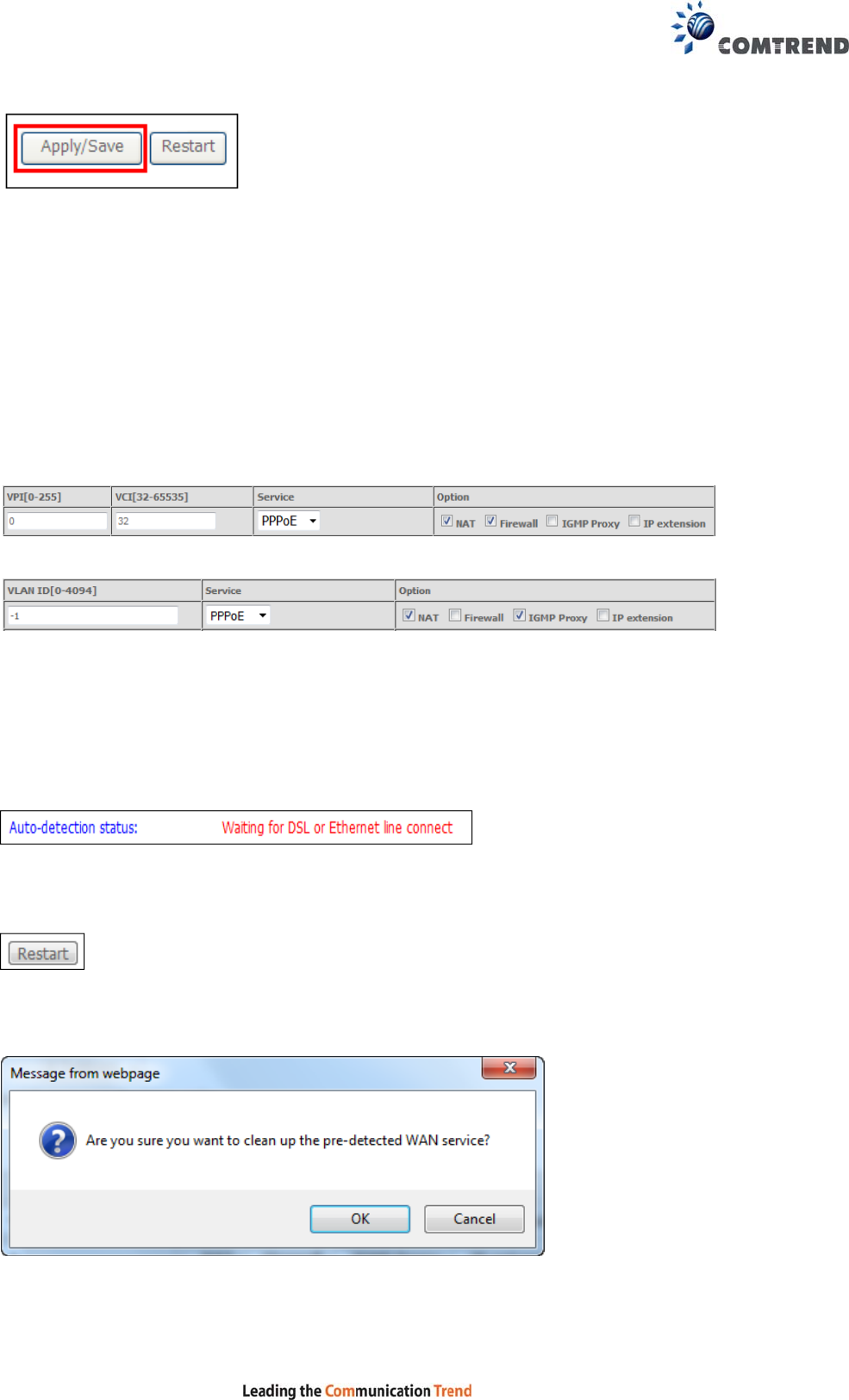
79
Click "Apply/Save" to activate the auto-detect function.
Options for each WAN service: These options are selectable for each WAN
service. Users can pre-configure both WAN services and other provided settings to
meet their deployed requirements.
Auto Detection status and Restart
The Auto-detection status is used to display the real time status of the
Auto-detection feature.
The Restart button is used to detect all the WAN services that are either detected
by the auto-detection feature or configured manually by users.
The following window will pop up upon clicking the Restart button. Click the OK
button to proceed.

80
Auto Detection notice
Note: The following description concerning ETHWAN is for multiple LAN port devices
only.
1) This feature will automatically detect one WAN service only. If customers require
multiple WAN services, manual configuration is required.
2) If a physical ETHWAN port is detected, the Auto Detection for ETHWAN will be
fixed on the physical ETHWAN port and cannot be configured for any LAN port;
if the physical ETHWAN port is not detected, the Auto Detection for ETHWAN will
be configured to the 4th LAN port by default and allows it to be configured for any
LAN port as well.
3) For cases in which both the DSL port and ETHWAN port are plugged in at the
same time, the DSL WAN will have priority over ETHWAN. For example, the
ETHWAN port is plugged in with a WAN service detected automatically and then
the DSL port is plugged in and linked up. The Auto Detection feature will clear
the WAN service for ETHWAN and re-detect the WAN service for DSL port.
4) If none of the pre-configured services are detected, a Bridge service will be
created.
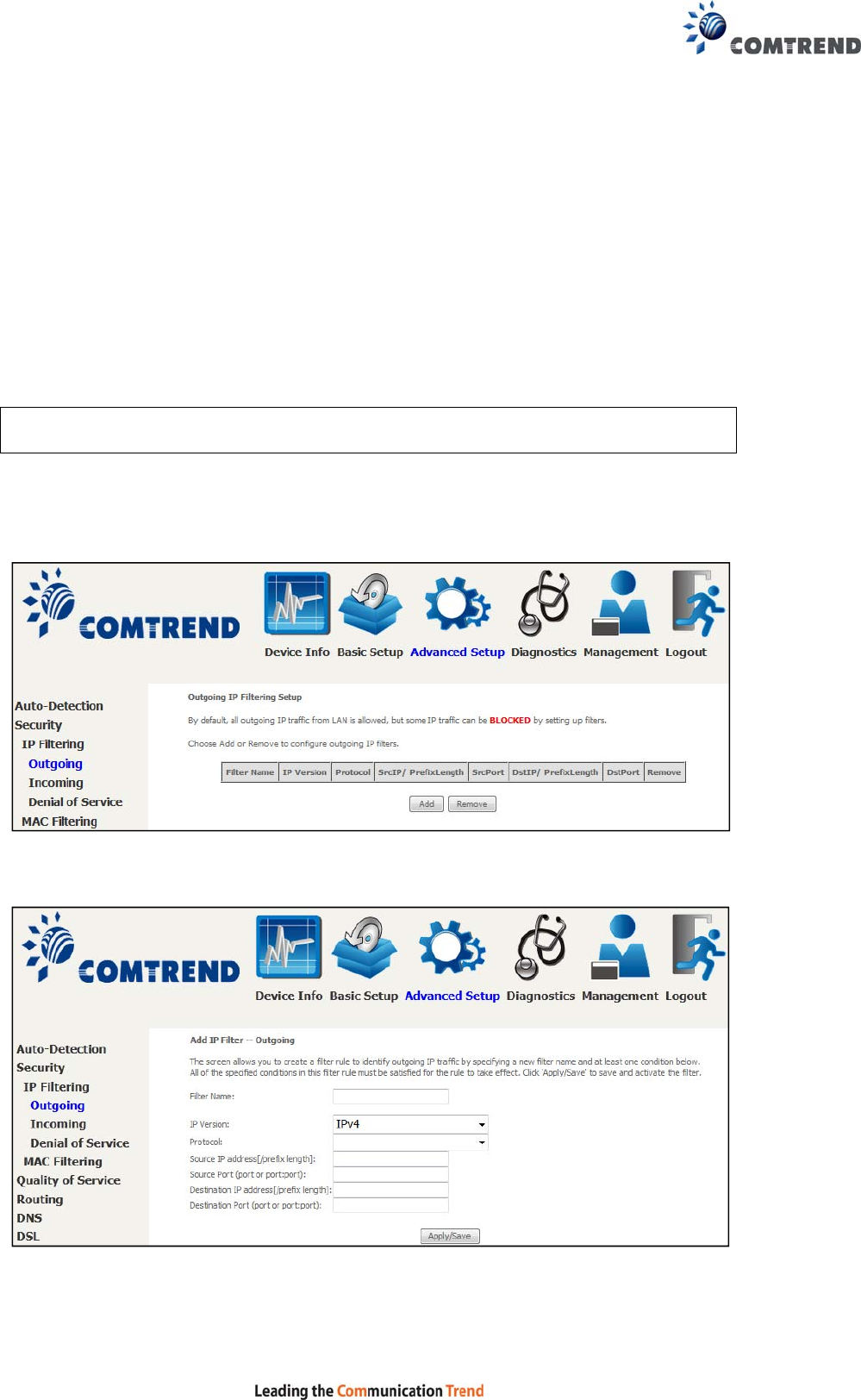
81
6.2 Security
For detailed descriptions, with examples, please consult Appendix A - Firewall.
6.2.1 IP Filtering
This screen sets filter rules that limit IP traffic (Outgoing/Incoming). Multiple filter
rules can be set and each applies at least one limiting condition. For individual IP
packets to pass the filter all conditions must be fulfilled.
NOTE: This function is not available when in bridge mode. Instead, MAC Filtering
performs a similar function.
OUTGOING IP FILTER
By default, all outgoing IP traffic is allowed, but IP traffic can be blocked with filters.
To add a filter (to block some outgoing IP traffic), click the Add button.
On the following screen, enter your filter criteria and then click Apply/Save.
Consult the table below for field descriptions.
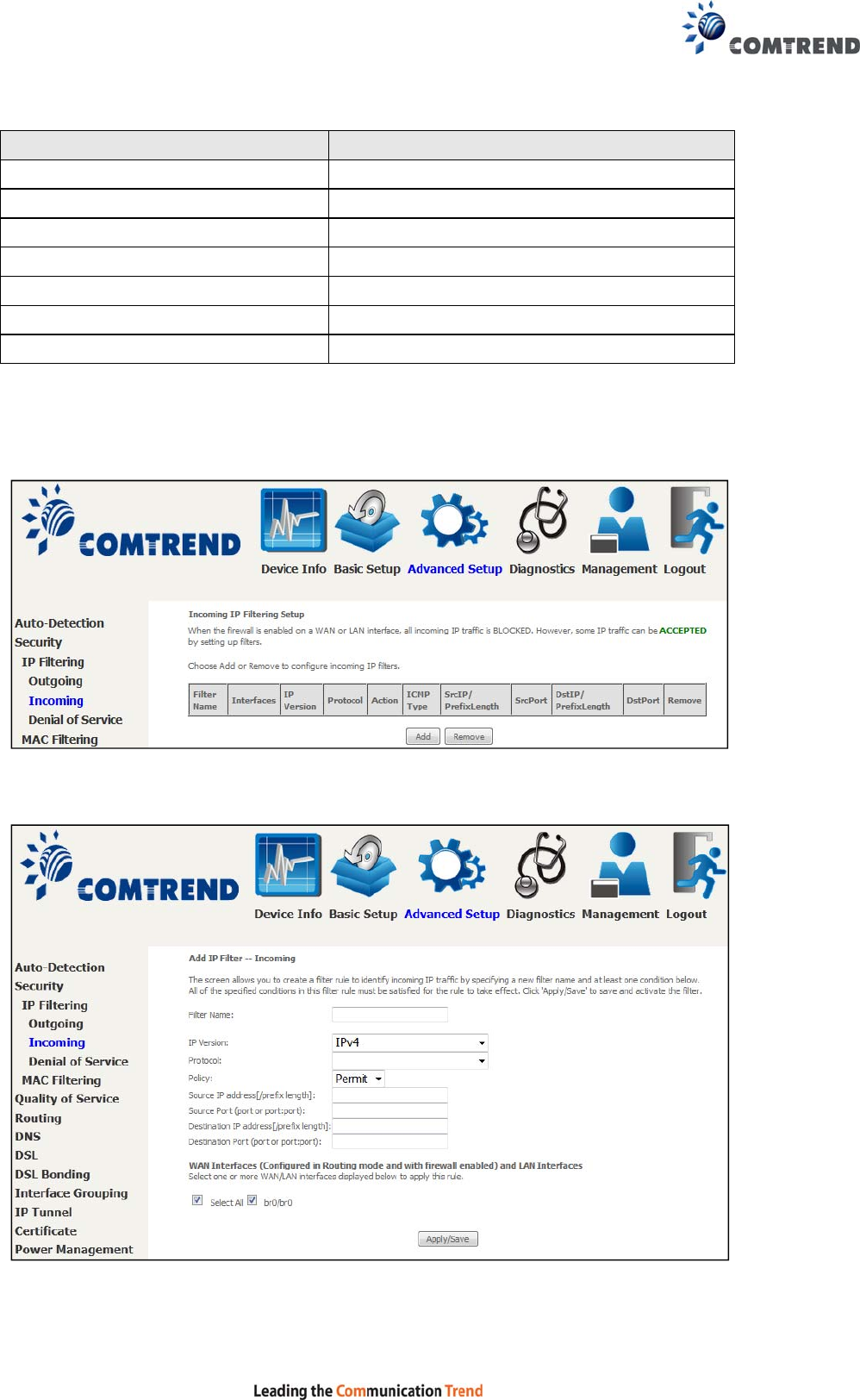
82
Field Description
Filter Name The filter rule label.
IP Version Select from the drop down menu.
Protocol TCP, TCP/UDP, UDP, or ICMP.
Source IP address Enter source IP address.
Source Port (port or port:port) Enter source port number or range.
Destination IP address Enter destination IP address.
Destination Port (port or port:port)
Enter destination port number or range.
INCOMING IP FILTER
By default, all incoming IP traffic is blocked, but IP traffic can be allowed with filters.
To add a filter (to allow incoming IP traffic), click the Add button.
On the following screen, enter your filter criteria and then click Apply/Save.
Consult the table below for field descriptions.

83
Field Description
Filter Name The filter rule label.
IP Version Select from the drop down menu.
Protocol TCP, TCP/UDP, UDP, or ICMP.
Policy Permit/Drop packets specified by the firewall
rule.
Source IP address Enter source IP address.
Source Port (port or port:port) Enter source port number or range.
Destination IP address Enter destination IP address.
Destination Port (port or port:port)
Enter destination port number or range.
At the bottom of this screen, select the WAN and LAN Interfaces to which the filter
rule will apply. You may select all or just a subset. WAN interfaces in bridge mode or
without firewall enabled are not available.
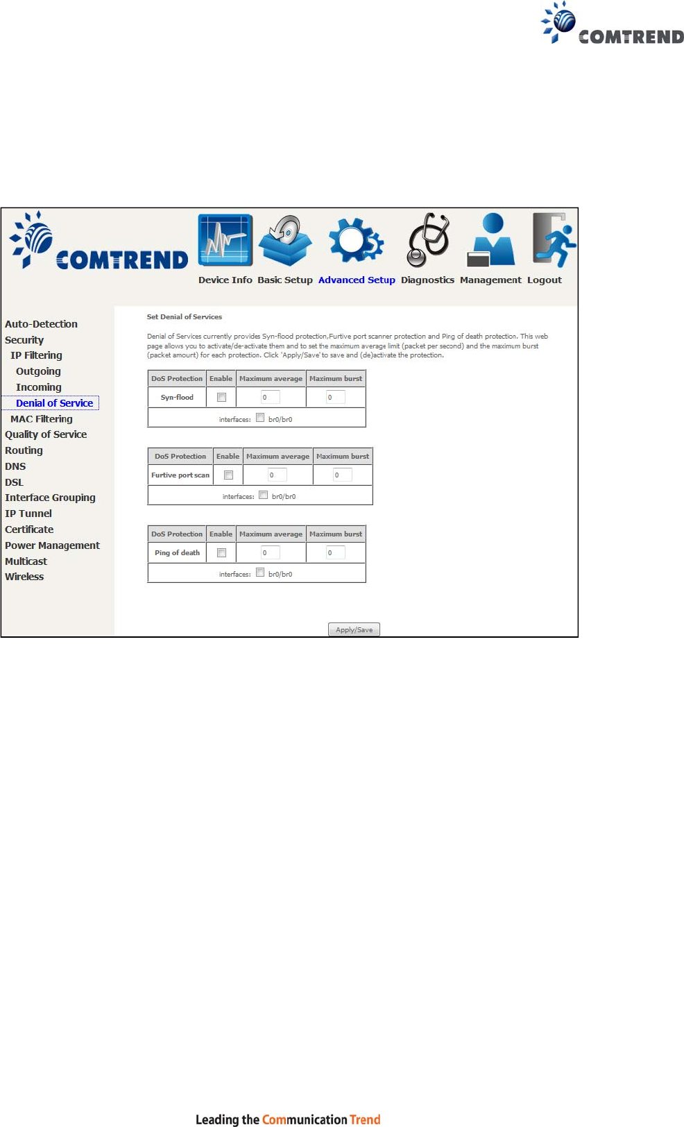
84
Denial of Service
Denial of Services currently provides Syn-flood protection, furtive port scanner
protection and Ping of death protection. This web page allows you to
activate/de-activate them and to set the maximum average limit (packet per second)
and the maximum burst (packet amount) for each protection.
Click the Apply/Save button to save and (de)activate the protection.
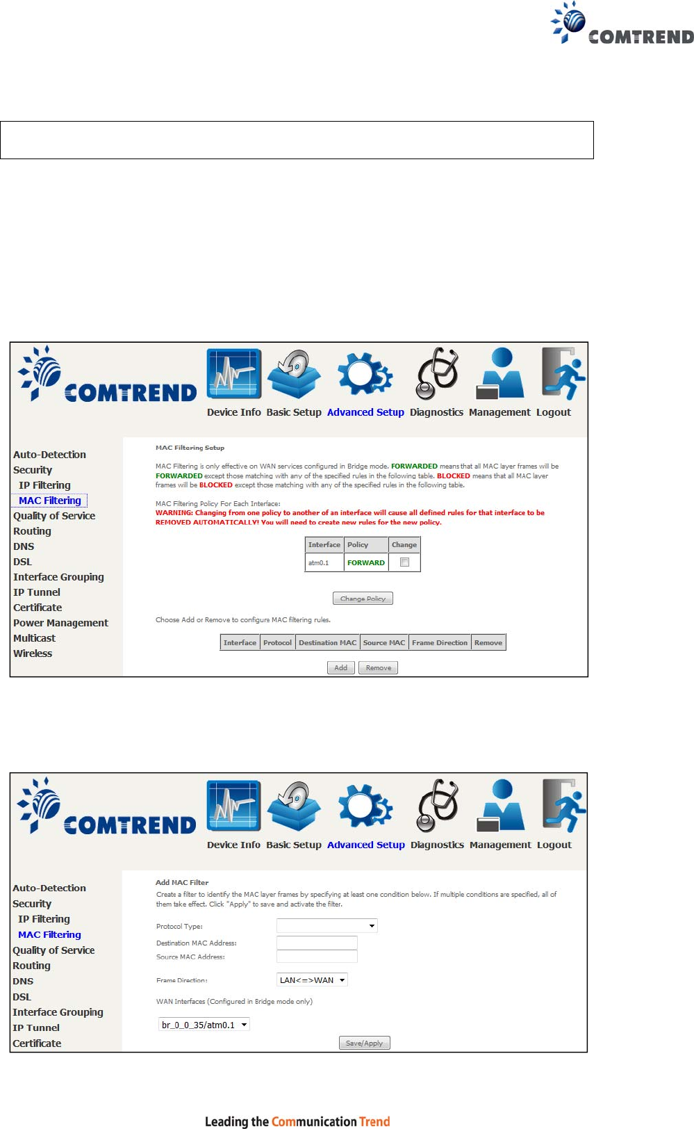
85
6.2.2 MAC Filtering
NOTE: This option is only available in bridge mode. Other modes use IP Filtering
to perform a similar function.
Each network device has a unique 48-bit MAC address. This can be used to filter
(block or forward) packets based on the originating device. MAC filtering policy and
rules for the VR-3060 can be set according to the following procedure.
The MAC Filtering Global Policy is defined as follows. FORWARDED means that all
MAC layer frames will be FORWARDED except those matching the MAC filter rules.
BLOCKED means that all MAC layer frames will be BLOCKED except those
matching the MAC filter rules. The default MAC Filtering Global policy is
FORWARDED. It can be changed by clicking the Change Policy button.
Choose Add or Remove to configure MAC filtering rules. The following screen will
appear when you click Add. Create a filter to identify the MAC layer frames by
specifying at least one condition below. If multiple conditions are specified, all of
them must be met.

86
Click Save/Apply to save and activate the filter rule.
Consult the table below for detailed field descriptions.
Field Description
Protocol Type PPPoE, IPv4, IPv6, AppleTalk, IPX, NetBEUI, IGMP
Destination MAC Address Defines the destination MAC address
Source MAC Address Defines the source MAC address
Frame Direction Select the incoming/outgoing packet interface
WAN Interfaces Applies the filter to the selected bridge interface
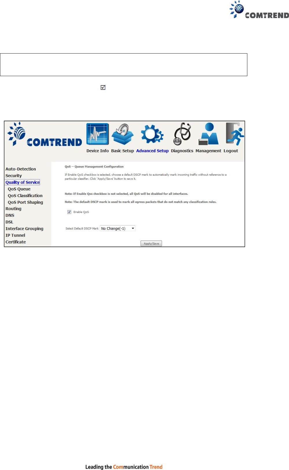
87
6.3 Quality of Service (QoS)
NOTE: QoS must be enabled in at least one PVC to display this option.
(See Appendix F - Connection Setup for detailed PVC setup instructions).
To Enable QoS tick the checkbox and select a Default DSCP Mark.
Click Apply/Save to activate QoS.
QoS and DSCP Mark are defined as follows:
Quality of Service (QoS): This provides different priority to different users or data
flows, or guarantees a certain level of performance to a data flow in accordance with
requests from Queue Prioritization.
Default Differentiated Services Code Point (DSCP) Mark: This specifies the per hop
behavior for a given flow of packets in the Internet Protocol (IP) header that do not
match any other QoS rule.

88
6.3.1 QoS Queue
6.3.1.1 QoS Queue Configuration
Configure queues with different priorities to be used for QoS setup.
In ATM mode, a maximum of 16 queues can be configured.
In PTM mode, a maximum of 8 queues can be configured.
For each Ethernet interface, a maximum of 8 queues can be configured.
For each Ethernet interface, a maximum of 8 queues can be configured.
(Please see the screen on the following page).
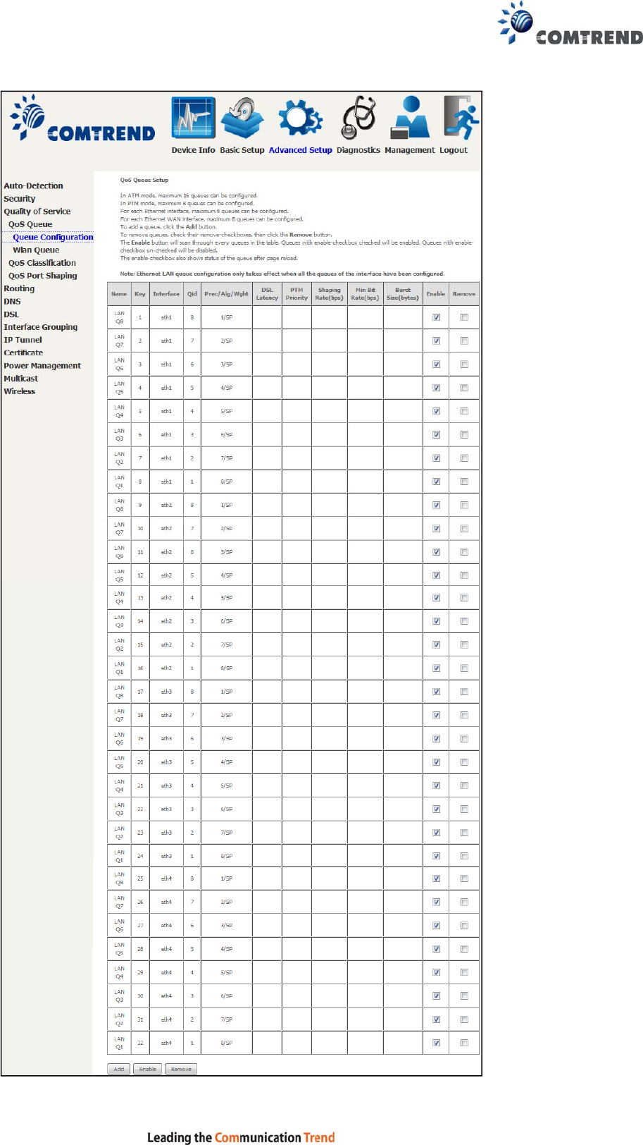
89
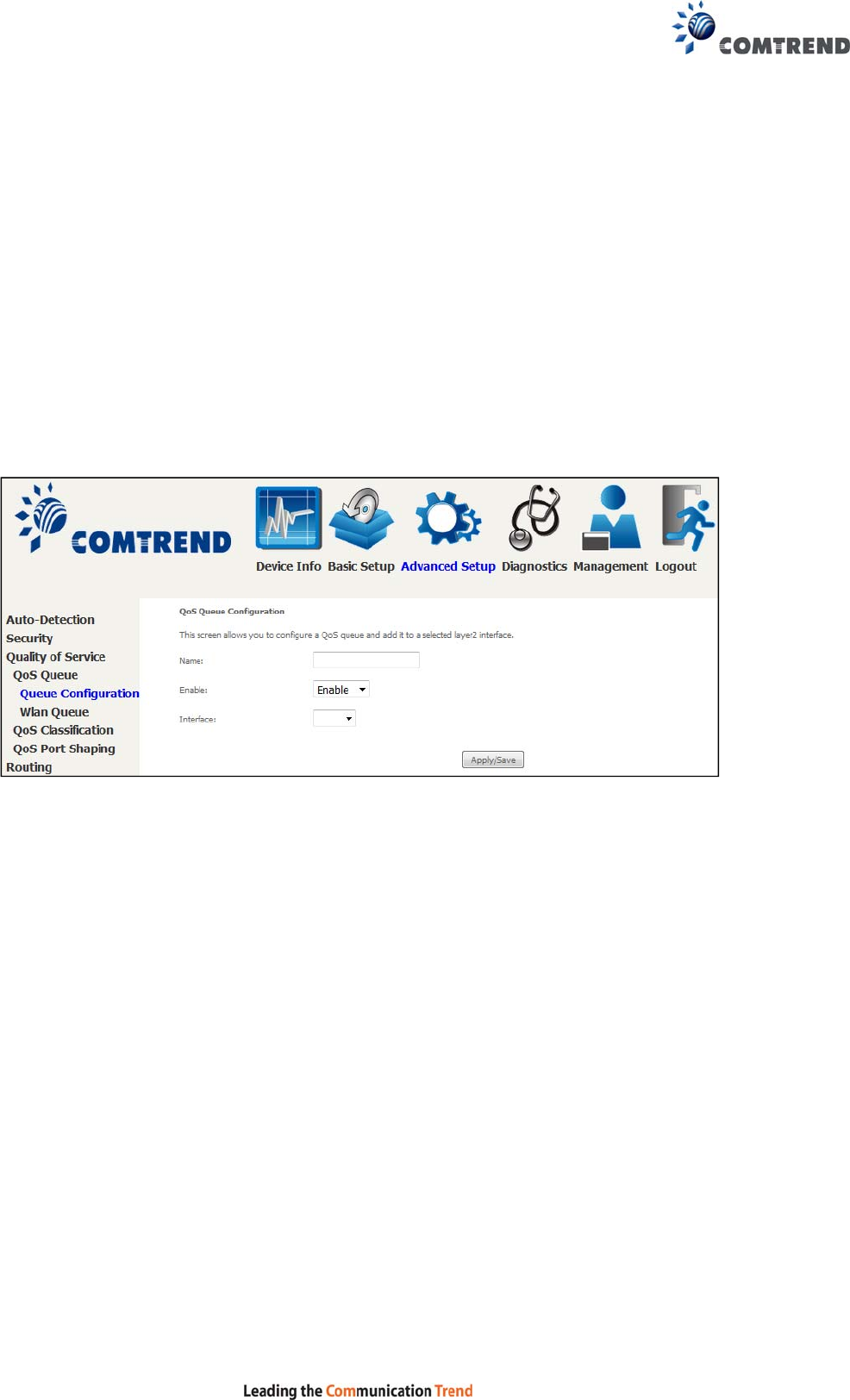
90
To remove queues, check their remove-checkboxes (for user created queues), then
click the Remove button.
The Enable button will scan through every queue in the table. Queues with the
enable-checkbox checked will be enabled. Queues with the enable-checkbox
un-checked will be disabled.
The enable-checkbox also shows status of the queue after page reload.
Note that if WMM function is disabled in the Wireless Page, queues related to
wireless will not take effect. This function follows the Differentiated Services rule of
IP QoS. You can create a new Queue entry by clicking the Add button.
Enable and assign an interface and precedence on the next screen. Click
Save/Reboot on this screen to activate it.
Click Add to display the following screen.
Name: Identifier for this Queue entry.
Enable: Enable/Disable the Queue entry.
Interface: Assign the entry to a specific network interface (QoS enabled).
After selecting an Interface the following will be displayed.
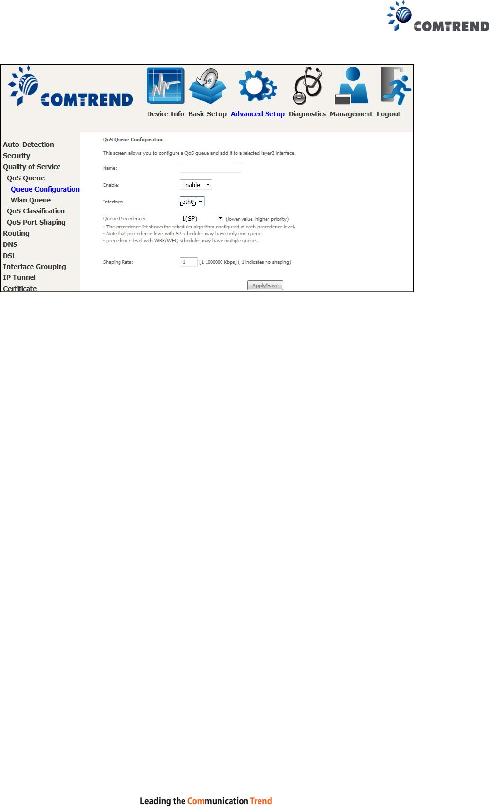
91
The precedence list shows the scheduler algorithm for each precedence level.
Queues of equal precedence will be scheduled based on the algorithm.
Queues of unequal precedence will be scheduled based on SP.
Shaping Rate: Specify a shaping rate limit to the defined queue.
Click Apply/Save to apply and save the settings.
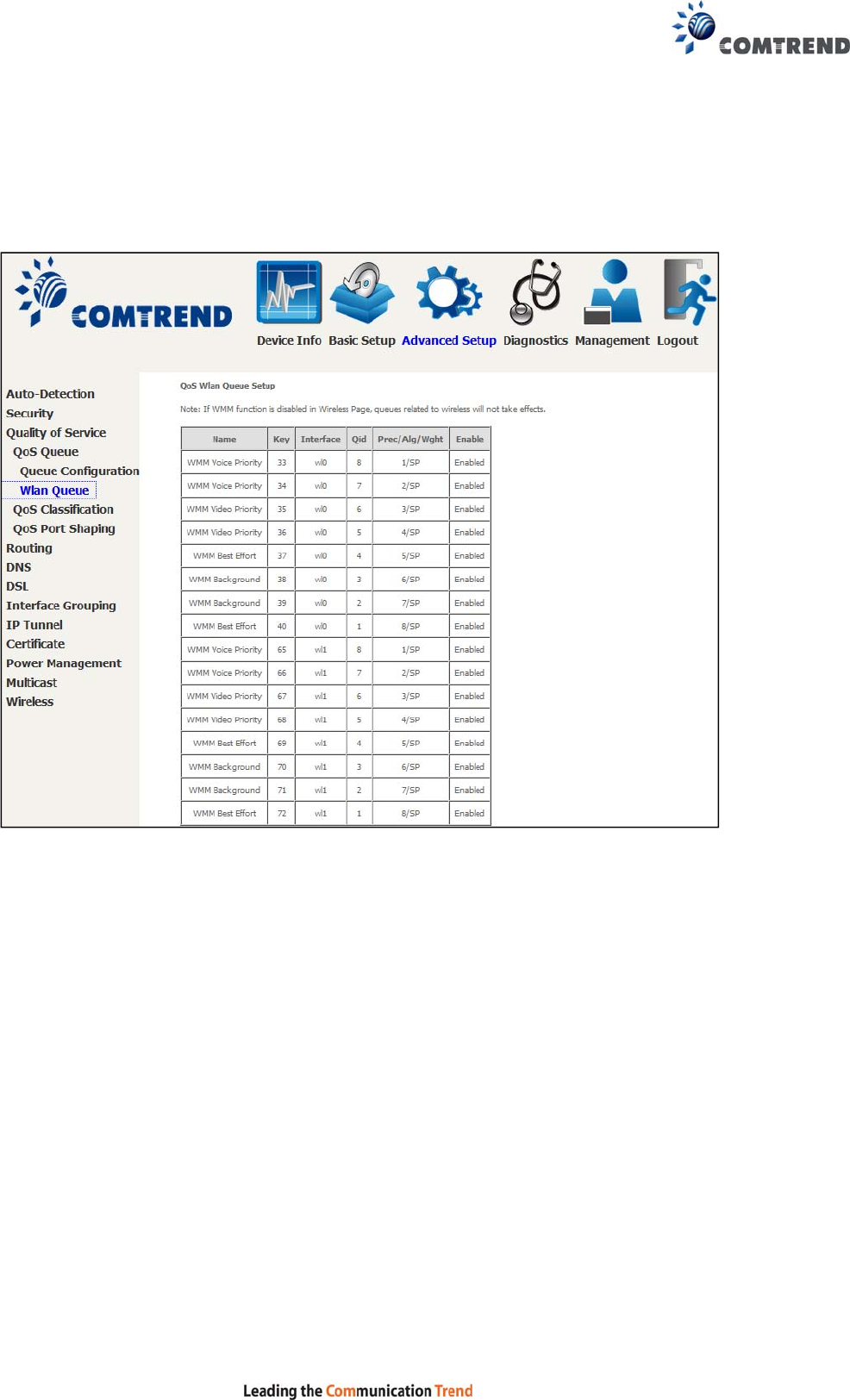
92
6.3.1.2 Wlan Queue
Displays the list of available wireless queues for WMM and wireless data transmit
priority.
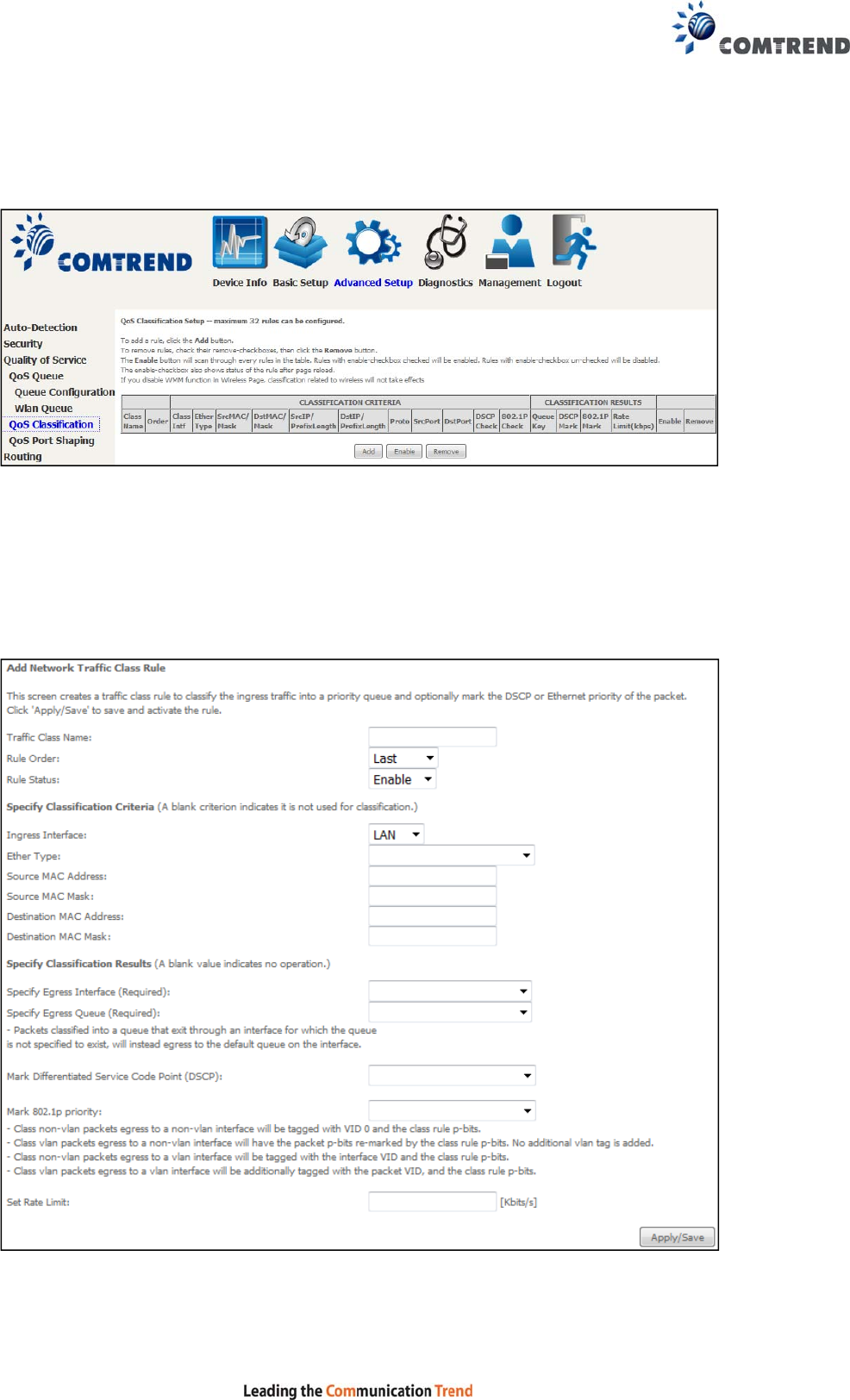
93
6.3.2 QoS Classification
The network traffic classes are listed in the following table.
Click Add to configure a network traffic class rule and Enable to activate it. To
delete an entry from the list, click Remove.
This screen creates a traffic class rule to classify the upstream traffic, assign
queuing priority and optionally overwrite the IP header DSCP byte. A rule consists of
a class name and at least one logical condition. All the conditions specified in the
rule must be satisfied for it to take effect.
Click Apply/Save to save and activate the rule.

94
Field Description
Traffic Class Name Enter a name for the traffic class.
Rule Order Last is the only option.
Rule Status Disable or enable the rule.
Classification Criteria
Ingress Interface Select an interface: (i.e. LAN, WAN, local, ETH1, ETH2,
ETH3, wl0)
Ether Type Set the Ethernet type (e.g. IP, ARP, IPv6).
Source MAC Address A packet belongs to SET-1, if a binary-AND of its source
MAC address with the Source MAC Mask is equal to the
binary-AND of the Source MAC Mask and this field.
Source MAC Mask This is the mask used to decide how many bits are checked
in Source MAC Address.
Destination MAC
Address A packet belongs to SET-1 then the result that the
Destination MAC Address of its header binary-AND to the
Destination MAC Mask must equal to the result that this
field binary-AND to the Destination MAC Mask.
Destination MAC Mask This is the mask used to decide how many bits are checked
in the Destination MAC Address.
Classification Results
Specify Egress
Interface Choose the egress interface from the available list.
Specify Egress Queue Choose the egress queue from the list of available for the
specified egress interface.
Mark Differentiated
Service Code Point The selected Code Point gives the corresponding priority to
packets that satisfy the rule.
Mark 802.1p Priority Select between 0-7.
- Class non-vlan packets egress to a non-vlan interface will
be tagged with VID 0 and the class rule p-bits.
- Class vlan packets egress to a non-vlan interface will
have the packet p-bits re-marked by the class rule p-bits.
No additional vlan tag is added.
- Class non-vlan packets egress to a vlan interface will be
tagged with the interface VID and the class rule p-bits.
- Class vlan packets egress to a vlan interface will be
additionally tagged with the packet VID, and the class rule
p-bits.
Set Rate Limit The data transmission rate limit in kbps.
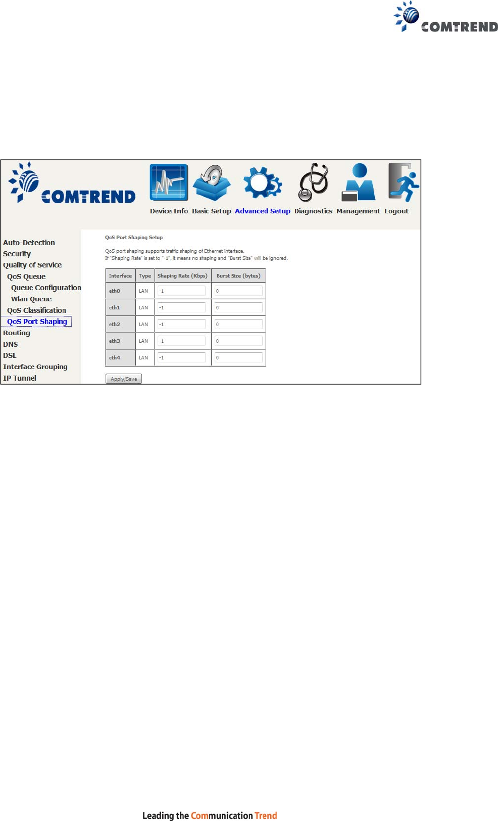
95
6.3.3 QoS Port Shaping
QoS port shaping supports traffic shaping of the Ethernet interface.
Input the shaping rate and burst size to enforce QoS rule on each interface.
If "Shaping Rate" is set to "-1", it means no shaping and "Burst Size" will be ignored.
Click Apply/Save to apply and save the settings.
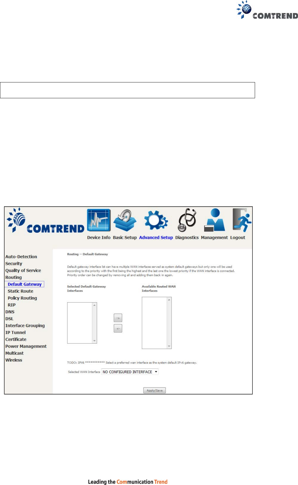
96
6.4 Routing
The following routing functions are accessed from this menu:
Default Gateway, Static Route, Policy Routing and RIP.
NOTE: In bridge mode, the RIP menu option is hidden while the other menu
options are shown but ineffective.
6.4.1 Default Gateway
The default gateway interface list can have multiple WAN interfaces served as
system default gateways but only one will be used according to the priority with the
first being the highest and the last one the lowest priority if the WAN interface is
connected. Priority order can be changed by removing all and adding them back in
again.
Click Apply/Save to apply and save the settings.
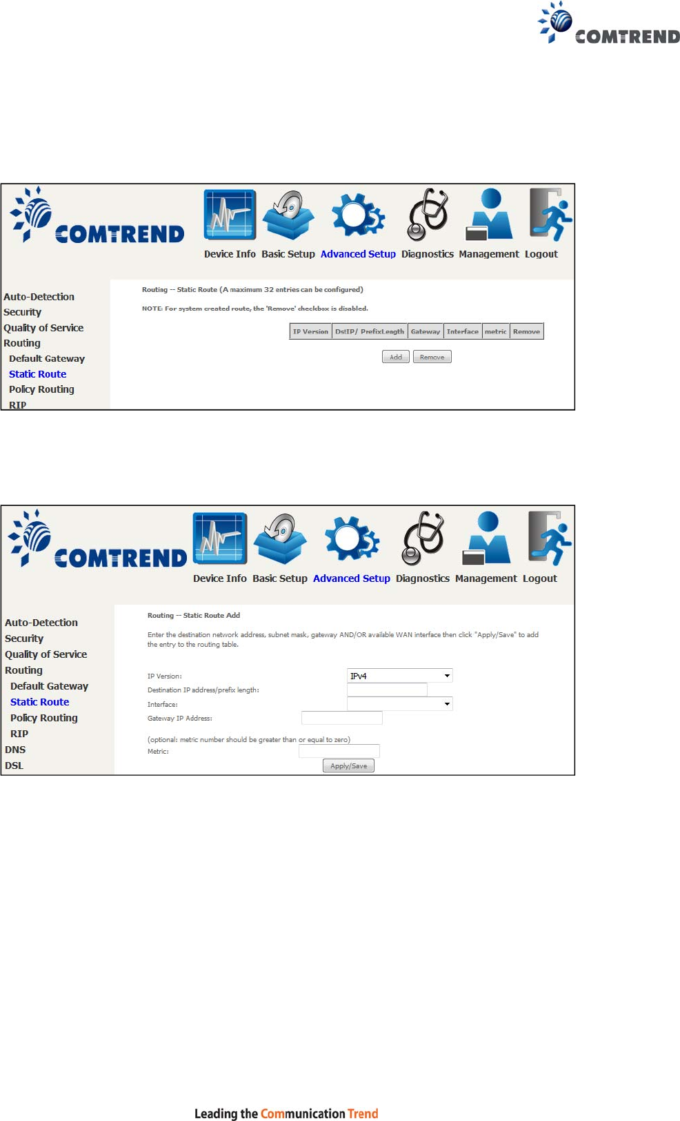
97
6.4.2 Static Route
This option allows for the configuration of static routes by destination IP.
Click Add to create a static route or click Remove to delete a static route.
After clicking Add the following will display.
IP Version: Select the IP version to be IPv4 or IPv6.
Destination IP address/prefix length: Enter the destination IP address.
Interface: Select the proper interface for the rule.
Gateway IP Address: The next-hop IP address.
Metric: The metric value of routing.
After completing the settings, click Apply/Save to add the entry to the routing
table.
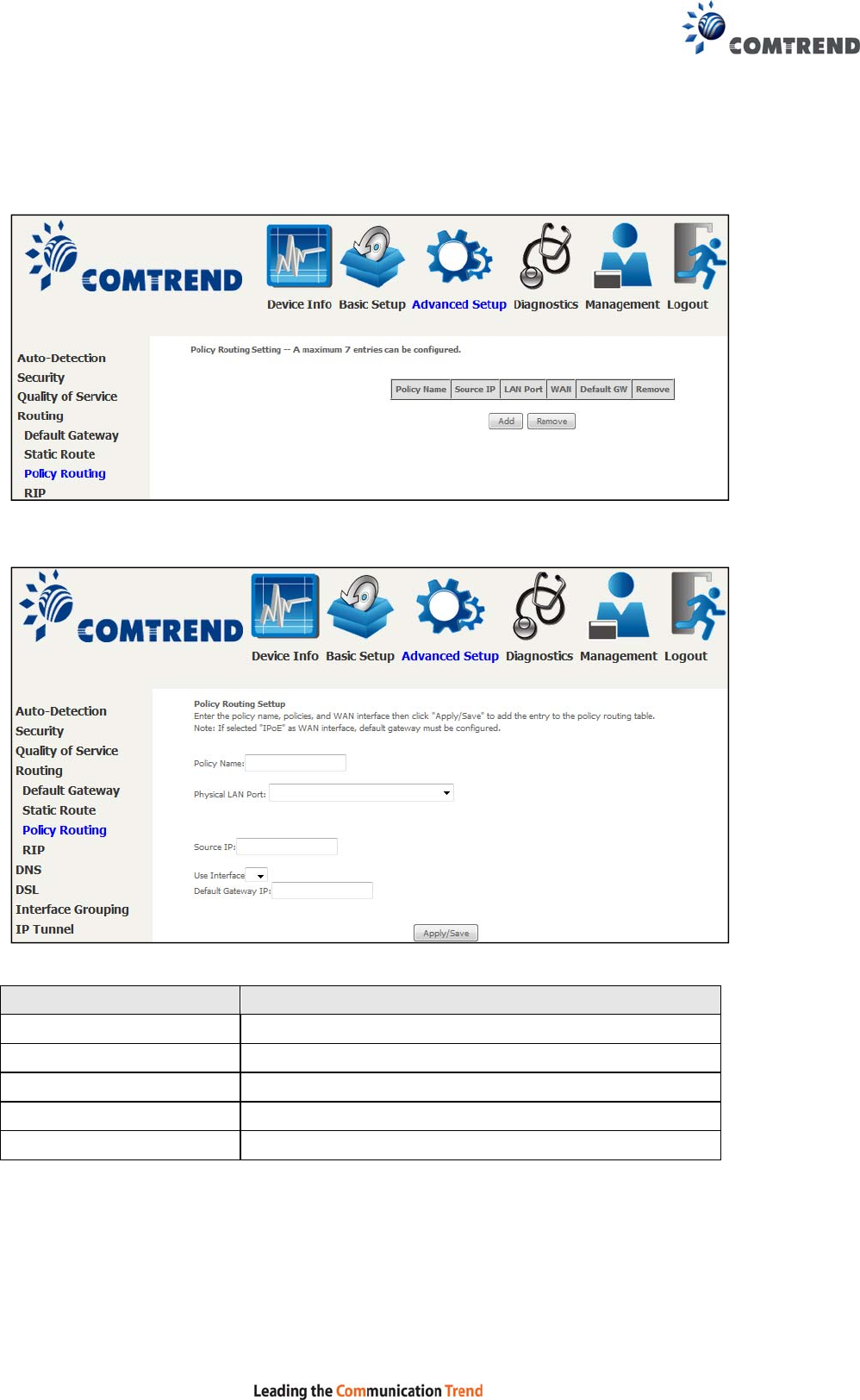
98
6.4.3 Policy Routing
This option allows for the configuration of static routes by policy.
Click Add to create a routing policy or Remove to delete one.
On the following screen, complete the form and click Apply/Save to create a policy.
Field Description
Policy Name Name of the route policy
Physical LAN Port Specify the port to use this route policy
Source IP IP Address to be routed
Use Interface Interface that traffic will be directed to
Default Gateway IP IP Address of the default gateway
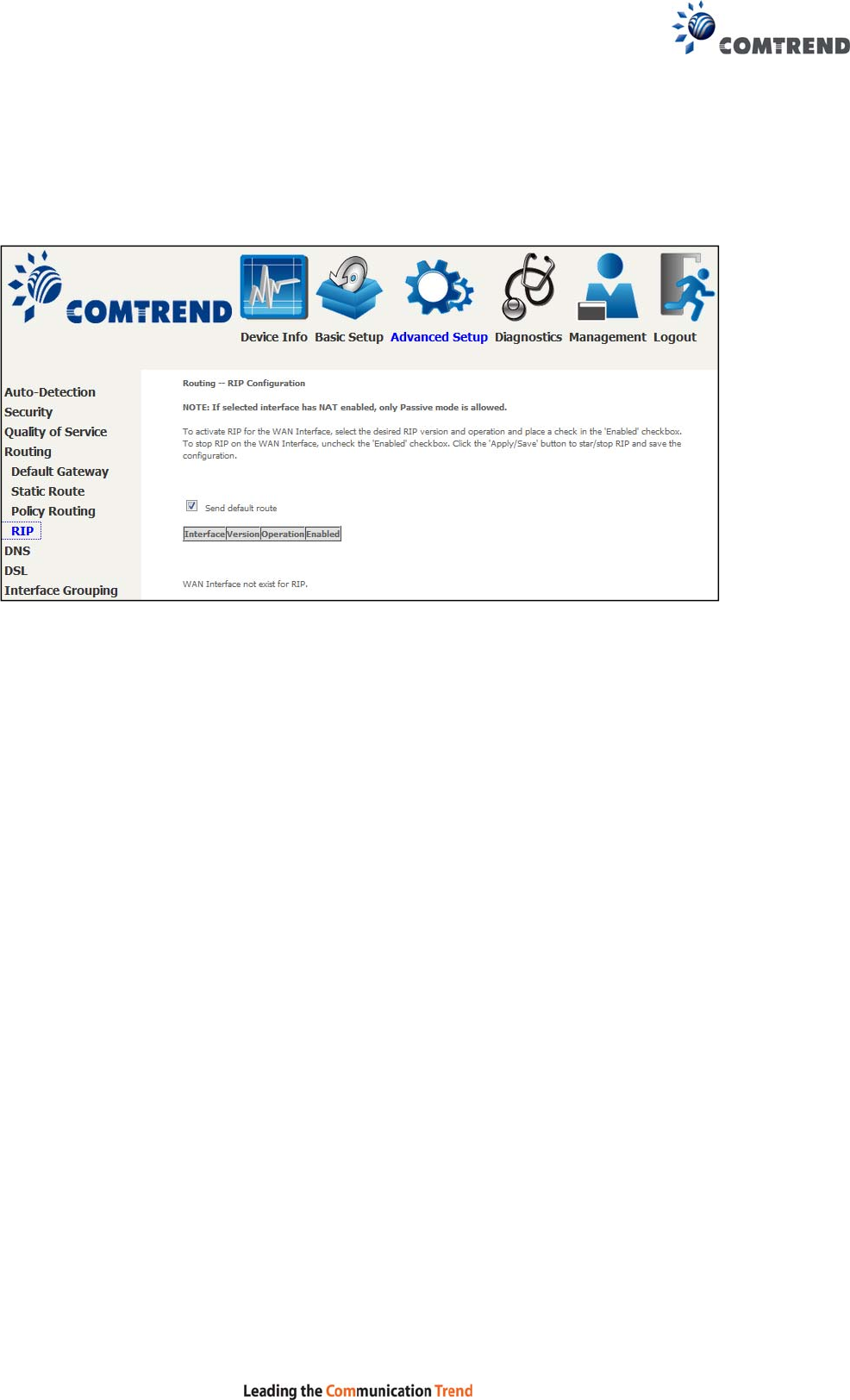
99
6.4.4 RIP
To activate RIP, configure the RIP version/operation mode and select the Enabled
checkbox for at least one WAN interface before clicking Save/Apply.
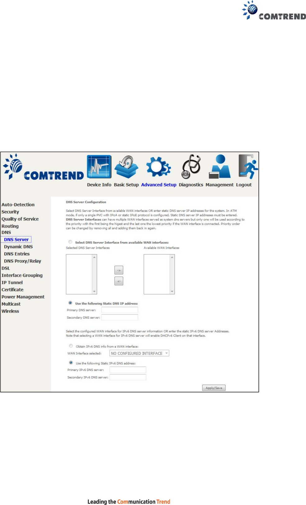
100
6.5 DNS
6.5.1 DNS Server
Select DNS Server Interface from available WAN interfaces OR enter static DNS
server IP addresses for the system. In ATM mode, if only a single PVC with IPoA or
static IPoE protocol is configured, Static DNS server IP addresses must be entered.
DNS Server Interfaces can have multiple WAN interfaces served as system DNS
servers but only one will be used according to the priority with the first being the
highest and the last one the lowest priority if the WAN interface is connected.
Priority order can be changed by removing all and adding them back in again.
Click Apply/Save to save the new configuration.
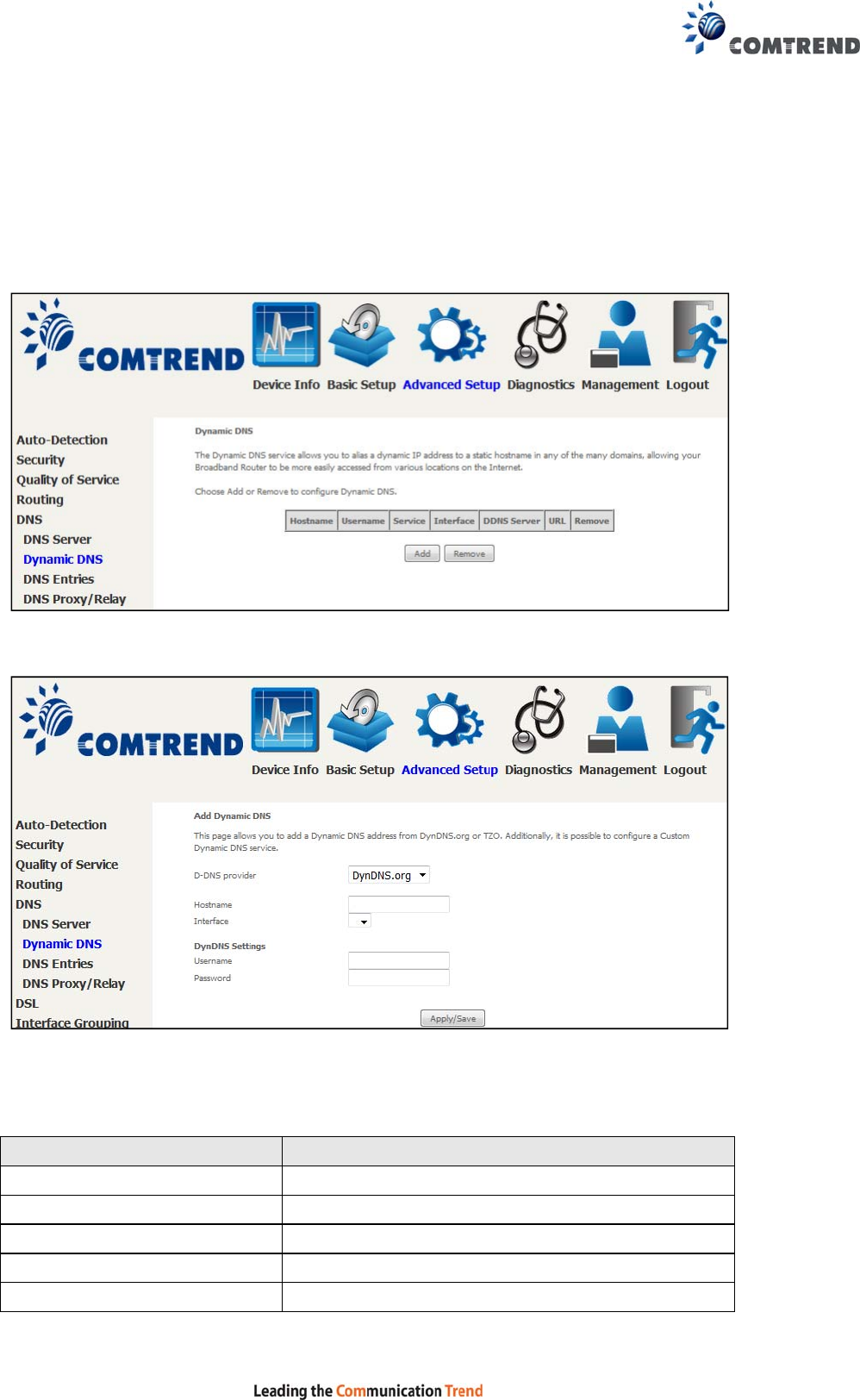
101
6.5.2 Dynamic DNS
The Dynamic DNS service allows you to map a dynamic IP address to a static
hostname in any of many domains, allowing the VR-3060 to be more easily accessed
from various locations on the Internet.
To add a dynamic DNS service, click Add. The following screen will display.
Click Apply/Save to save your settings.
Consult the table below for field descriptions.
Field Description
D-DNS provider Select a dynamic DNS provider from the list
Hostname Enter the name of the dynamic DNS server
Interface Select the interface from the list
Username Enter the username of the dynamic DNS server
Password Enter the password of the dynamic DNS server
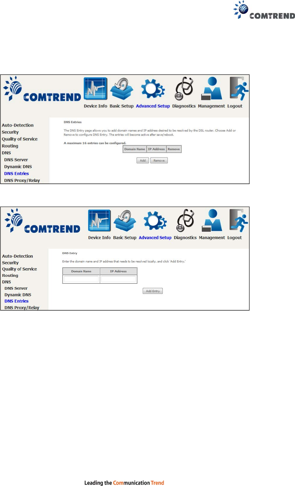
102
6.5.3 DNS Entries
The DNS Entry page allows you to add domain name and IP address pairs desired to
be resolved by the DSL router.
Choose Add or Remove to configure a DNS Entry. The entries will become active
after save/reboot.
Enter the domain name and IP address that needs to be resolved locally, and click
the Add Entry button.
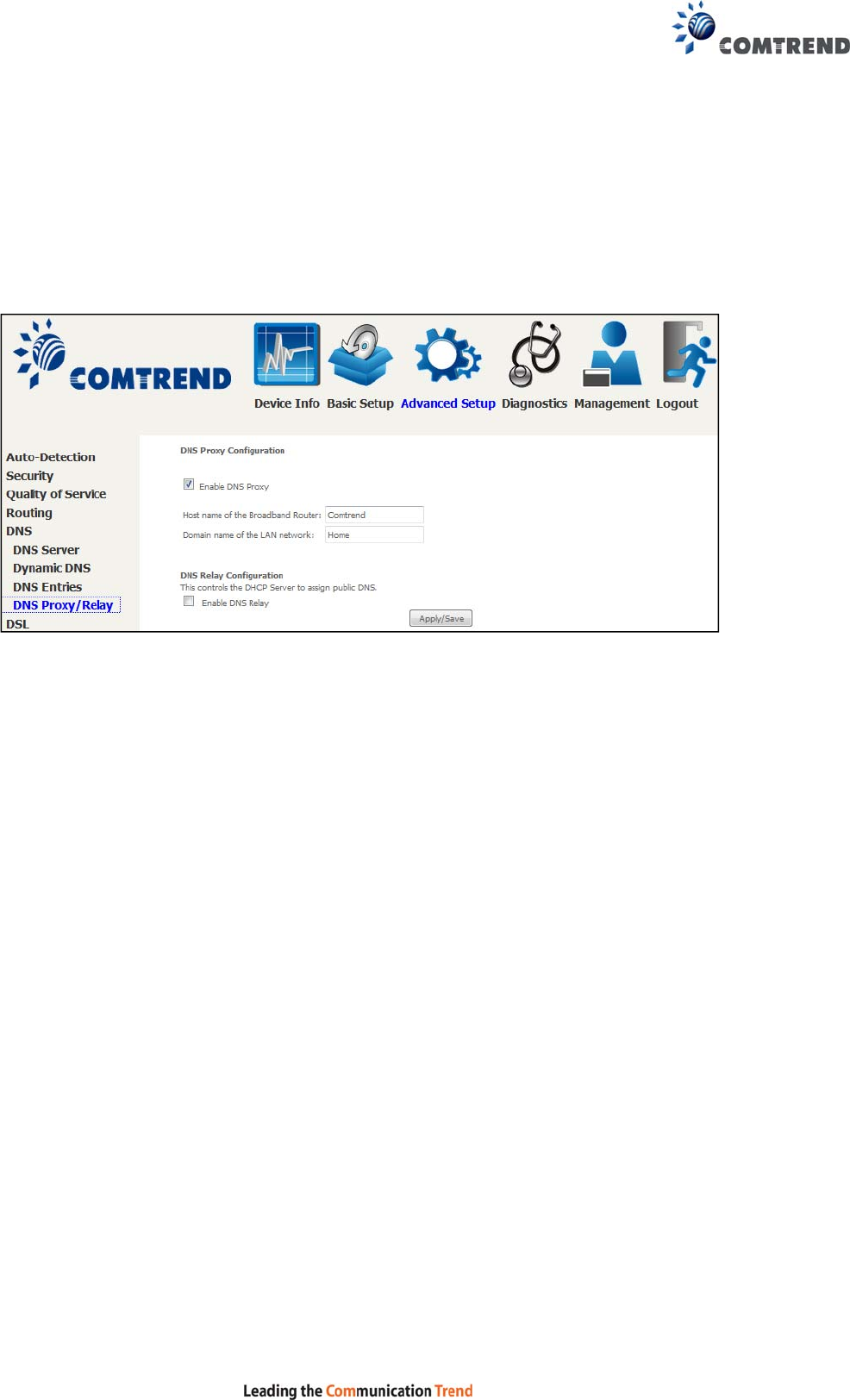
103
6.5.4 DNS Proxy/Relay
DNS proxy receives DNS queries and forwards DNS queries to the Internet. After the
CPE gets answers from the DNS server, it replies to the LAN clients. Configure DNS
proxy with the default setting, when the PC gets an IP via DHCP, the domain name,
Home, will be added to PC’s DNS Suffix Search List, and the PC can access route with
“Comtrend.Home”.
Click Apply/Save to apply and save the settings.
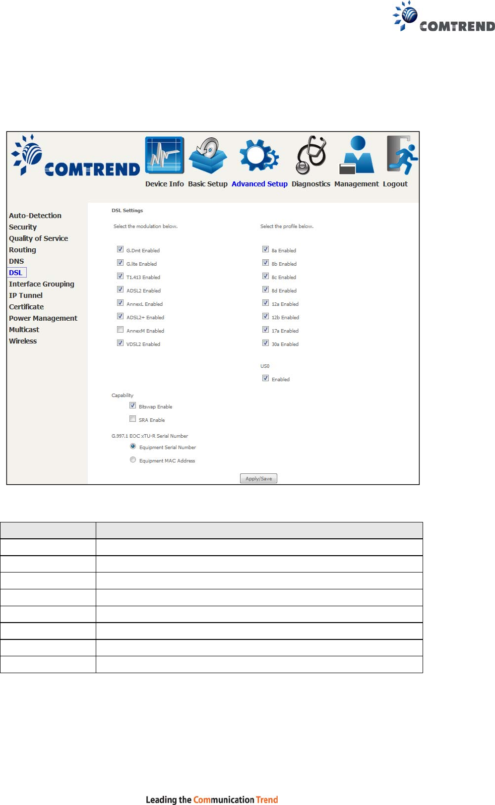
104
6.6 DSL
The DSL Settings screen allows for the selection of DSL modulation modes.
For optimum performance, the modes selected should match those of your ISP.
DSL Mode Data Transmission Rate - Mbps (Megabits per second)
G.Dmt Downstream: 12 Mbps Upstream: 1.3 Mbps
G.lite Downstream: 4 Mbps Upstream: 0.5 Mbps
T1.413 Downstream: 8 Mbps Upstream: 1.0 Mbps
ADSL2 Downstream: 12 Mbps Upstream: 1.0 Mbps
AnnexL Supports longer loops but with reduced transmission rates
ADSL2+ Downstream: 24 Mbps Upstream: 1.0 Mbps
AnnexM Downstream: 24 Mbps Upstream: 3.5 Mbps
VDSL2 Downstream: 100 Mbps Upstream: 60 Mbps

105
VDSL Profile Maximum Downstream Throughput- Mbps (Megabits per
second)
8a Downstream 50
8b Downstream 50
8c Downstream: 50
8d Downstream: 50
12a Downstream: 68
12b Downstream: 68
17a Downstream: 100
30a Downstream: 100 Mbps Upstream: 100 Mbps
Options Description
US0 Band between 20 and 138 kHz for long loops to upstream
Bitswap Enable Enables adaptive handshaking functionality
SRA Enable Enables Seamless Rate Adaptation (SRA)
G997.1 EOC
xTU-R Serial
Number
Select Equipment Serial Number or Equipment MAC Address to
use router’s serial number or MAC address in ADSL EOC
messages
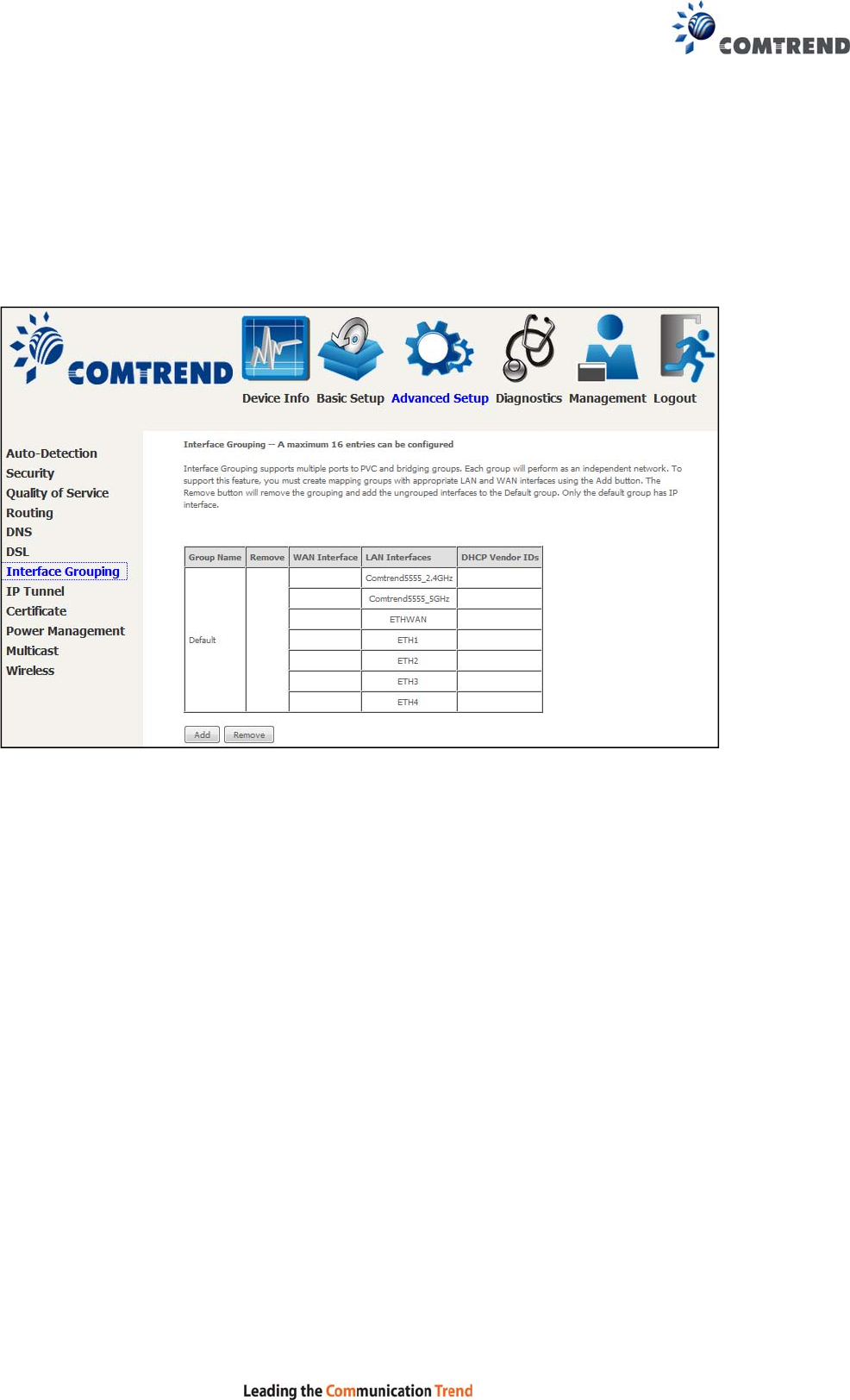
106
6.7 Interface Grouping
Interface Grouping supports multiple ports to PVC and bridging groups. Each group
performs as an independent network. To use this feature, you must create mapping
groups with appropriate LAN and WAN interfaces using the Add button.
The Remove button removes mapping groups, returning the ungrouped interfaces
to the Default group. Only the default group has an IP interface.
To add an Interface Group, click the Add button. The following screen will appear.
It lists the available and grouped interfaces. Follow the instructions shown
onscreen.
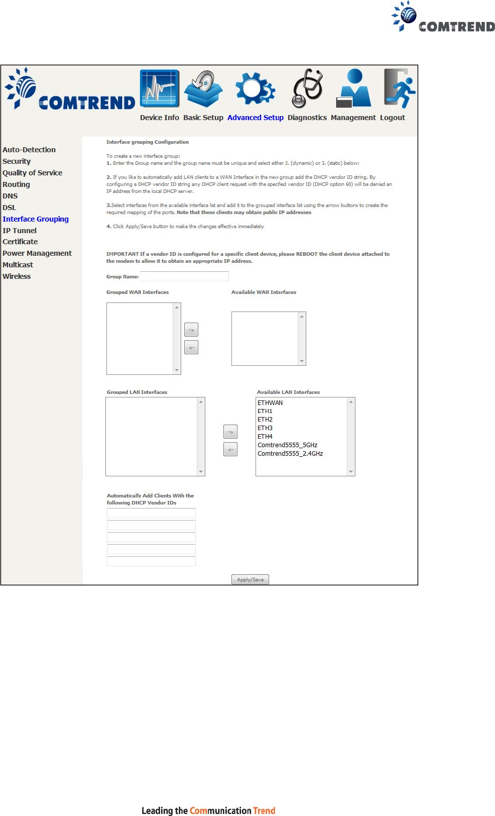
107
Automatically Add Clients With Following DHCP Vendor IDs:
Add support to automatically map LAN interfaces to PVC's using DHCP vendor ID
(option 60). The local DHCP server will decline and send the requests to a remote
DHCP server by mapping the appropriate LAN interface. This will be turned on when
Interface Grouping is enabled.
For example, imagine there are 4 PVCs (0/33, 0/36, 0/37, 0/38). VPI/VCI=0/33 is
for PPPoE while the other PVCs are for IP set-top box (video). The LAN interfaces are
ETH1, ETH2, ETH3, and ETH4.

108
The Interface Grouping configuration will be:
1. Default: ETH1, ETH2, ETH3, and ETH4.
2. Video: nas_0_36, nas_0_37, and nas_0_38. The DHCP vendor ID is "Video".
If the onboard DHCP server is running on "Default" and the remote DHCP server is
running on PVC 0/36 (i.e. for set-top box use only). LAN side clients can get IP
addresses from the CPE's DHCP server and access the Internet via PPPoE (0/33).
If a set-top box is connected to ETH1 and sends a DHCP request with vendor ID
"Video", the local DHCP server will forward this request to the remote DHCP server.
The Interface Grouping configuration will automatically change to the following:
1. Default: ETH2, ETH3, and ETH4
2. Video: nas_0_36, nas_0_37, nas_0_38, and ETH1.
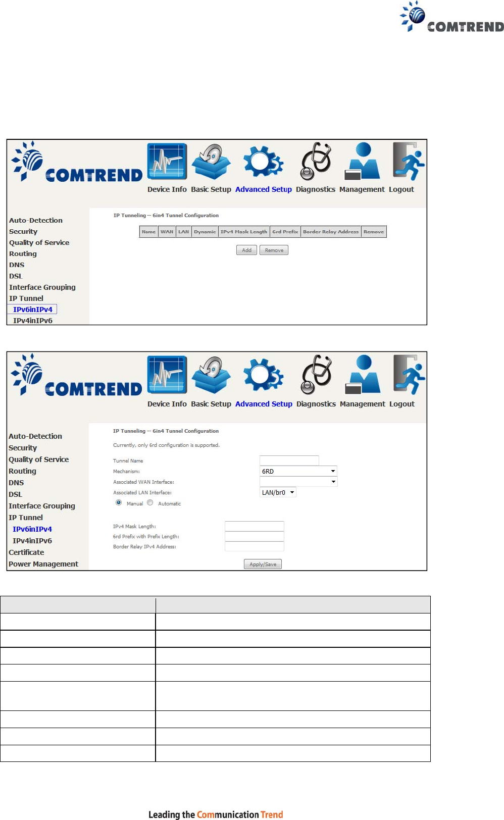
109
6.8 IP Tunnel
6.8.1 IPv6inIPv4
Configure 6in4 tunneling to encapsulate IPv6 traffic over explicitly-configured IPv4
links.
Click the Add button to display the following.
Click Apply/Save to apply and save the settings.
Options Description
Tunnel Name Input a name for the tunnel
Mechanism Mechanism used by the tunnel deployment
Associated WAN Interface Select the WAN interface to be used by the tunnel
Associated LAN Interface Select the LAN interface to be included in the tunnel
Manual/Automatic Select automatic for point-to-multipoint tunneling /
manual for point-to-point tunneling
IPv4 Mask Length The subnet mask length used for the IPv4 interface
6rd Prefix with Prefix Length Prefix and prefix length used for the IPv6 interface
Border Relay IPv4 Address Input the IPv4 address of the other device
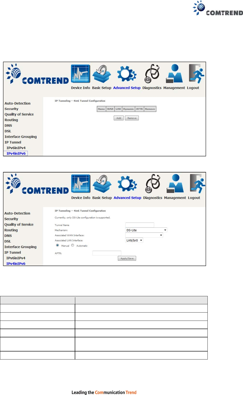
110
6.8.2 IPv4inIPv6
Configure 4in6 tunneling to encapsulate IPv4 traffic over an IPv6-only environment.
Click the Add button to display the following.
Click Apply/Save to apply and save the settings.
Options Description
Tunnel Name Input a name for the tunnel
Mechanism Mechanism used by the tunnel deployment
Associated WAN Interface Select the WAN interface to be used by the tunnel
Associated LAN Interface Select the LAN interface to be included in the tunnel
Manual/Automatic Select automatic for point-to-multipoint tunneling /
manual for point-to-point tunneling
AFTR Address of Address Family Translation Router
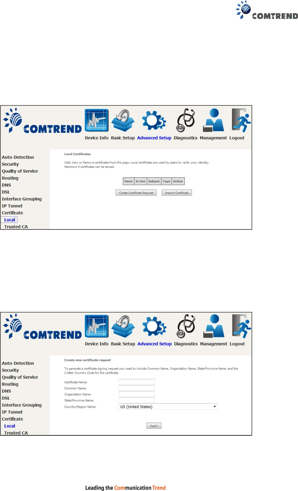
111
6.9 Certificate
A certificate is a public key, attached with its owner’s information (company name,
server name, personal real name, contact e-mail, postal address, etc) and digital
signatures. There will be one or more digital signatures attached to the certificate,
indicating that these entities have verified that this certificate is valid.
6.9.1 Local
CREATE CERTIFICATE REQUEST
Click Create Certificate Request to generate a certificate-signing request.
The certificate-signing request can be submitted to the vendor/ISP/ITSP to apply for
a certificate. Some information must be included in the certificate-signing request.
Your vendor/ISP/ITSP will ask you to provide the information they require and to
provide the information in the format they regulate. Enter the required information
and click Apply to generate a private key and a certificate-signing request.
The following table is provided for your reference.
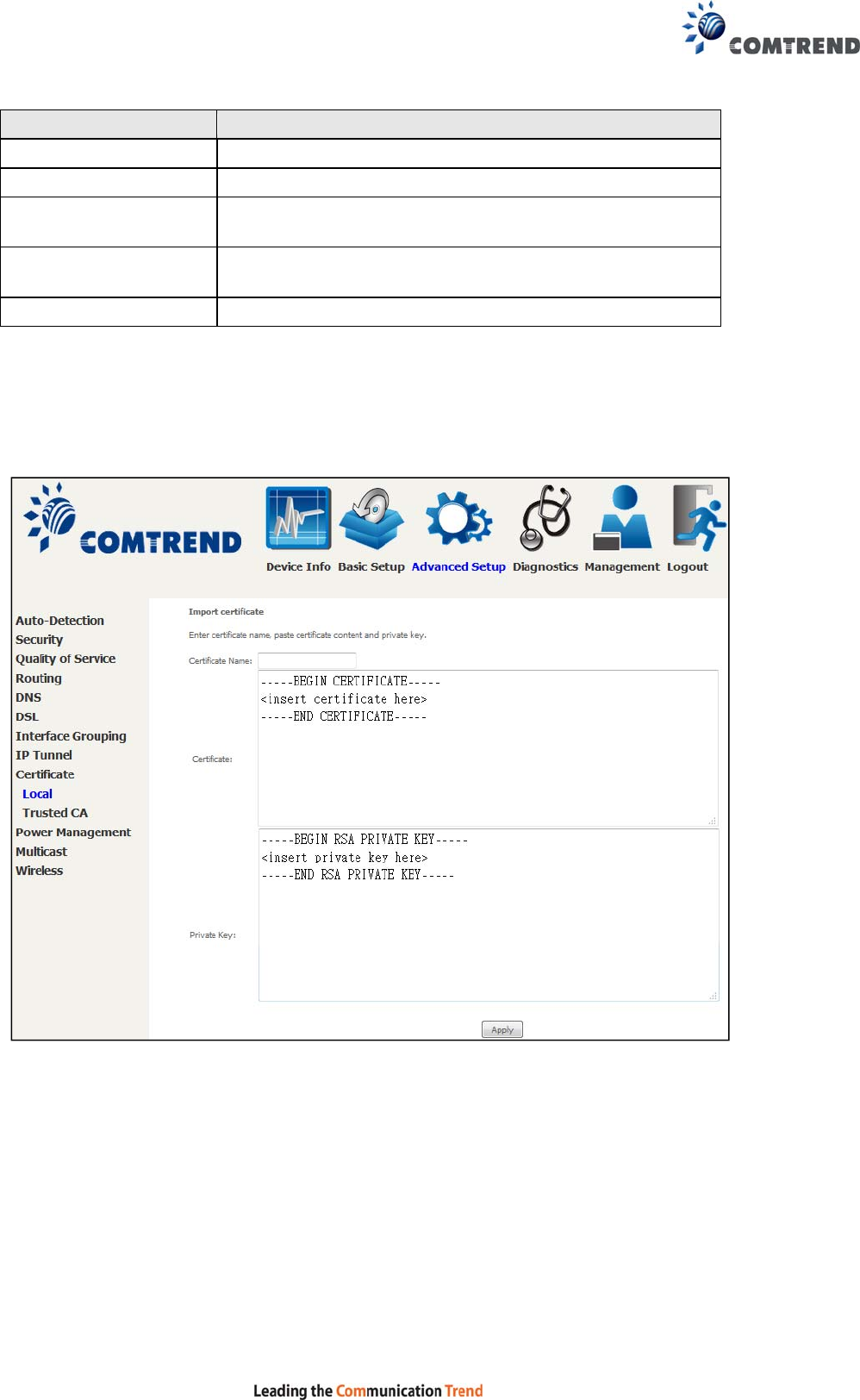
112
Field Description
Certificate Name A user-defined name for the certificate.
Common Name Usually, the fully qualified domain name for the machine.
Organization Name The exact legal name of your organization.
Do not abbreviate.
State/Province Name The state or province where your organization is located.
It cannot be abbreviated.
Country/Region Name The two-letter ISO abbreviation for your country.
IMPORT CERTIFICATE
Click Import Certificate to paste the certificate content and the private key
provided by your vendor/ISP/ITSP into the corresponding boxes shown below.
Enter a certificate name and click the Apply button to import the certificate and its
private key.
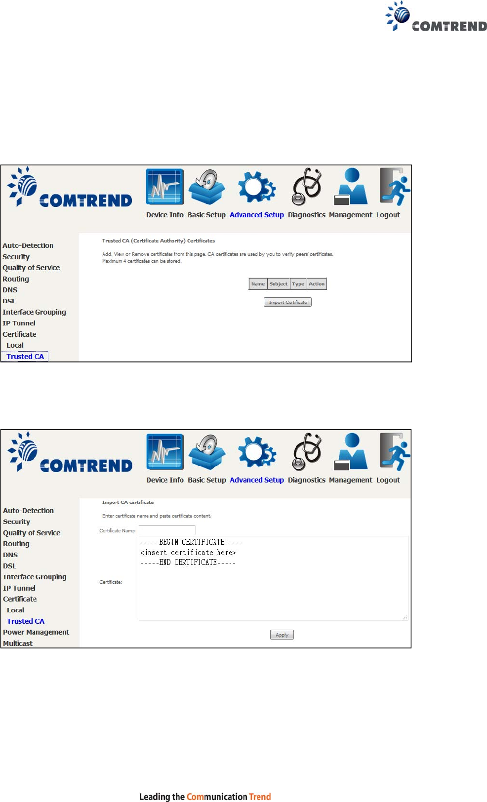
113
6.9.2 Trusted CA
CA is an abbreviation for Certificate Authority, which is a part of the X.509 system.
It is itself a certificate, attached with the owner information of this certificate
authority; but its purpose is not encryption/decryption. Its purpose is to sign and
issue certificates, in order to prove that these certificates are valid.
Click Import Certificate to paste the certificate content of your trusted CA. The
CA certificate content will be provided by your vendor/ISP/ITSP and is used to
authenticate the Auto-Configuration Server (ACS) that the CPE will connect to.
Enter a certificate name and click Apply to import the CA certificate.
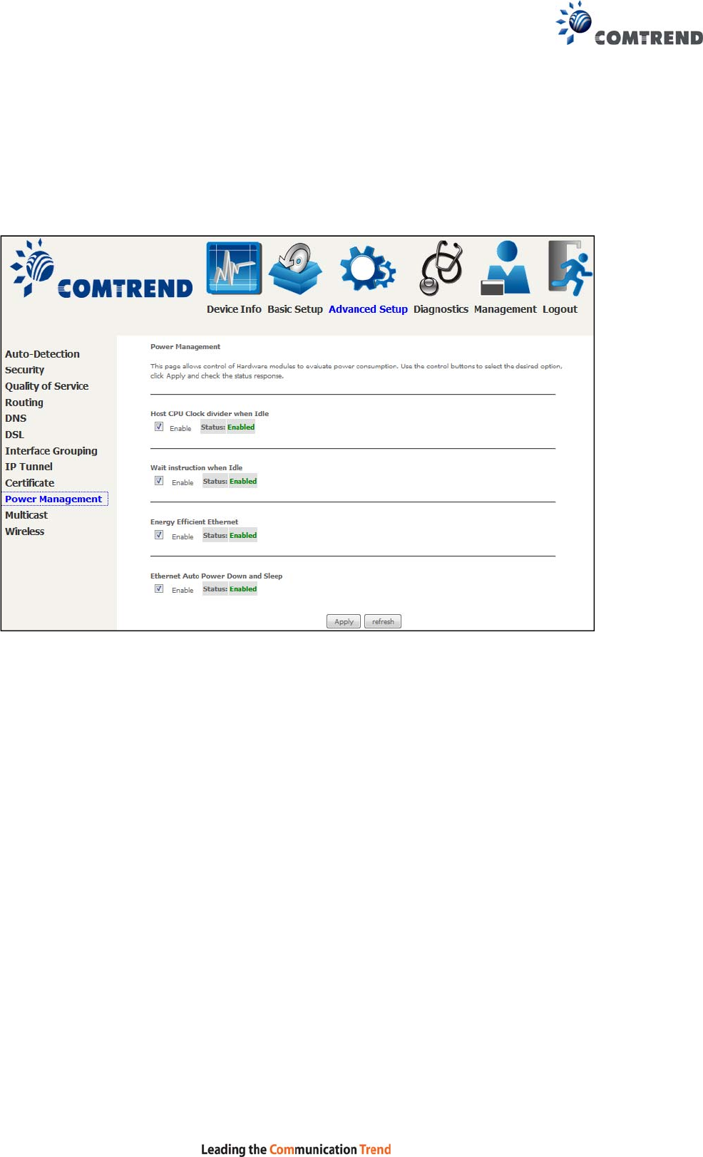
114
6.10 Power Management
This screen allows for control of hardware modules to evaluate power consumption.
Use the buttons to select the desired option, click Apply and check the response.
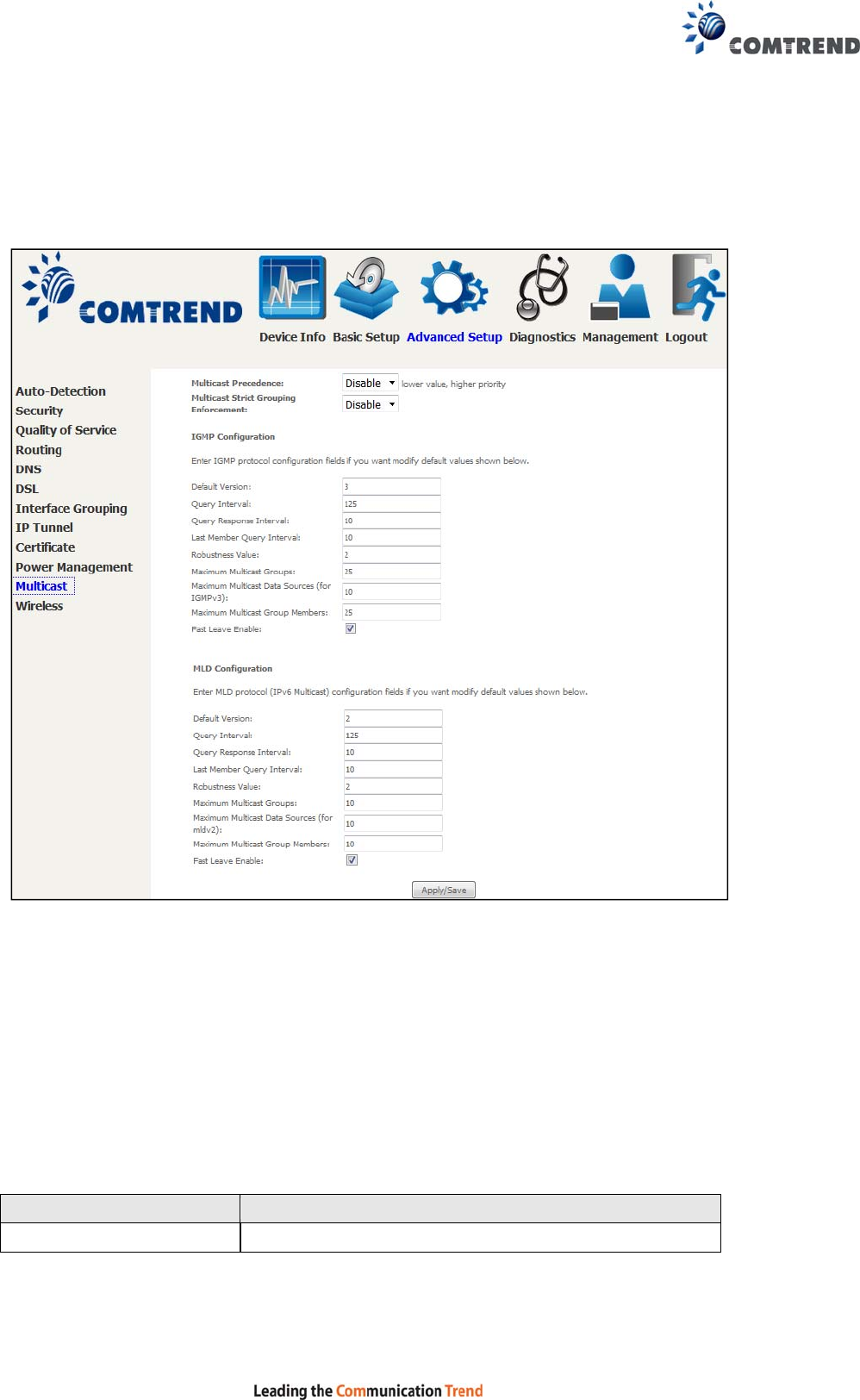
115
6.11 Multicast
Input new IGMP or MLD protocol configuration fields if you want modify default
values shown. Then click Apply/Save.
Multicast Precedence:
Select precedence of multicast packets.
Multicast Strict Grouping Enforcement:
Enable/Disable multicast strict grouping.
Field Description
Default Version Define IGMP using version with video server.

116
Field Description
Query Interval The query interval is the amount of time in seconds
between IGMP General Query messages sent by the
router (if the router is the querier on this subnet). The
default query interval is 125 seconds.
Query Response Interval The query response interval is the maximum amount
of time in seconds that the IGMP router waits to
receive a response to a General Query message. The
query response interval is the Maximum Response
Time field in the IGMP v2 Host Membership Query
message header. The default query response interval
is 10 seconds and must be less than the query
interval.
Last Member Query
Interval The last member query interval is the amount of time
in seconds that the IGMP router waits to receive a
response to a Group-Specific Query message. The last
member query interval is also the amount of time in
seconds between successive Group-Specific Query
messages. The default last member query interval is
10 seconds.
Robustness Value The robustness variable is a way of indicating how
susceptible the subnet is to lost packets. IGMP can
recover from robustness variable minus 1 lost IGMP
packets. The robustness variable should be set to a
value of 2 or greater. The default robustness variable
value is 2.
Maximum Multicast
Groups Setting the maximum number of Multicast groups.
Maximum Multicast Data
Sources (for IGMPv3) Define the maximum multicast video stream number.
Maximum Multicast
Group Members Setting the maximum number of groups that ports
can accept.
Fast Leave Enable When you enable IGMP fast-leave processing, the
switch immediately removes a port when it detects an
IGMP version 2 leave message on that port.
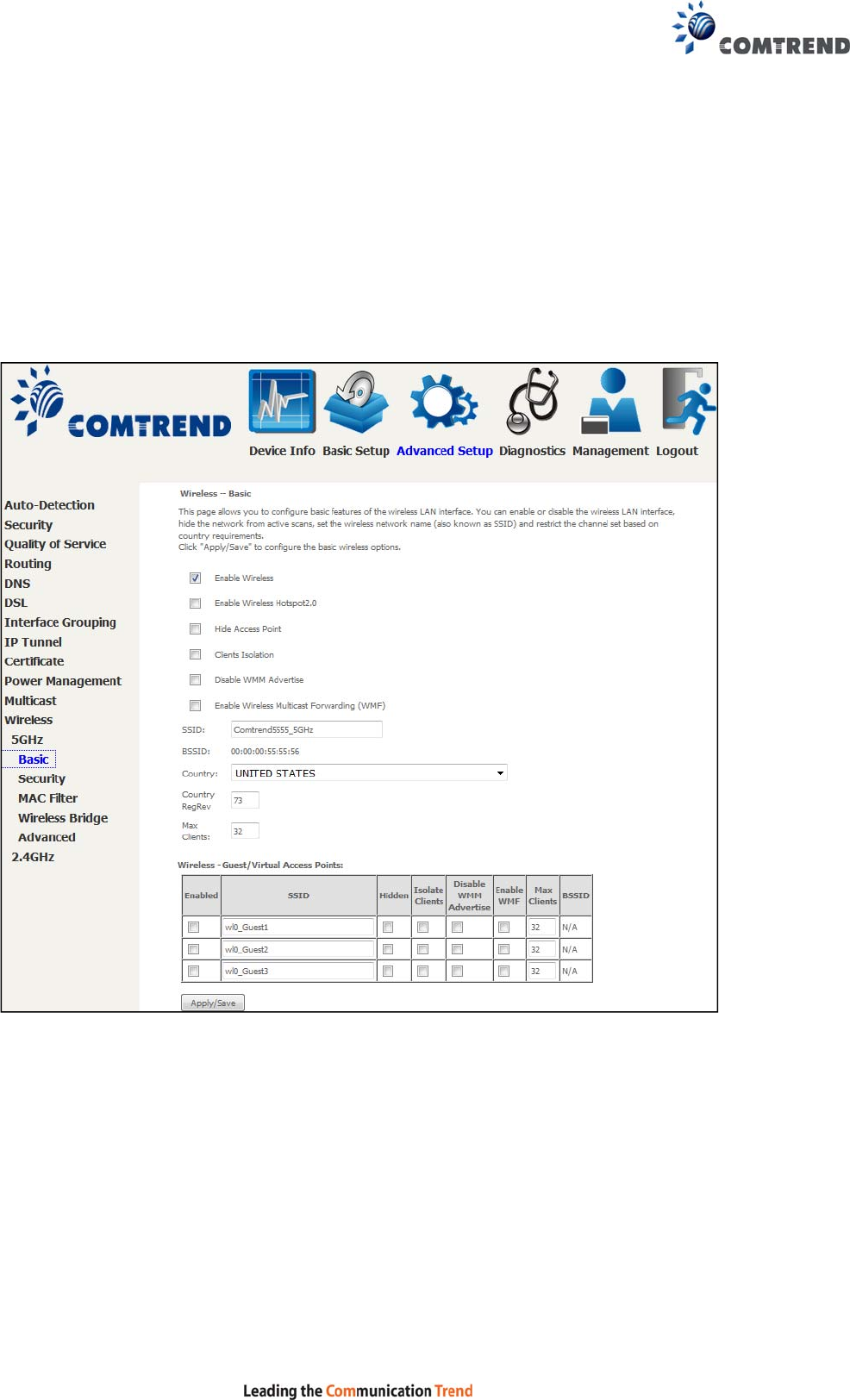
117
6.12 Wireless
6.12.1 Basic 5GHz
The Basic option allows you to configure basic features of the wireless LAN interface.
Among other things, you can enable or disable the wireless LAN interface, hide the
network from active scans, set the wireless network name (also known as SSID)
and restrict the channel set based on country requirements.
Click Apply/Save to configure the basic wireless options.
Consult the table below for descriptions of these options.

118
Option Description
Enable
Wireless A checkbox that enables or disables the wireless LAN interface.
When selected, a set of basic wireless options will appear.
Enable
Wireless
Hotspot2.0
Enable Wireless Hotspot 2.0 (Wi-Fi Certified Passpoint) on the
wireless interface.
Hide Access
Point Select Hide Access Point to protect the access point from detection by
wireless active scans. If the access point is hidden, it will not be listed
or listed with empty SSID in the scan result of wireless stations. To
connect a client to a hidden access point, the station must add the
access point manually to its wireless configuration.
Clients
Isolation When enabled, it prevents client PCs from seeing one another in My
Network Places or Network Neighborhood. Also, prevents one
wireless client communicating with another wireless client.
Disable
WMM
Advertise
Stops the router from ‘advertising’ its Wireless Multimedia (WMM)
functionality, which provides basic quality of service for time-sensitive
applications (e.g. VoIP, Video).
Enable
Wireless
Multicast
Forwarding
Select the checkbox to enable this function.
SSID
[1-32
characters]
Sets the wireless network name. SSID stands for Service Set
Identifier. All stations must be configured with the correct SSID to
access the WLAN. If the SSID does not match, that user will not be
granted access.
BSSID The BSSID is a 48-bit identity used to identify a particular BSS (Basic
Service Set) within an area. In Infrastructure BSS networks, the
BSSID is the MAC (Media Access Control) address of the AP (Access
Point); and in Independent BSS or ad hoc networks, the BSSID is
generated randomly.
Country A drop-down menu that permits worldwide and specific national
settings. Local regulations limit channel range:
US= worldwide, Japan=1-14, Jordan= 10-13, Israel= 1-13
Country
RegRev Wireless country code for transmit power limit.
Max Clients The maximum number of clients that can access the router.
Wireless -
Guest /
Virtual
Access
Points
This router supports multiple SSIDs called Guest SSIDs or Virtual
Access Points. To enable one or more Guest SSIDs select the
checkboxes in the Enabled column. To hide a Guest SSID select its
checkbox in the Hidden column.
Do the same for Isolate Clients and Disable WMM Advertise. For
a description of these two functions, see the previous entries for
“Clients Isolation” and “Disable WMM Advertise”. Similarly, for Enable
WMF, Max Clients and BSSID, consult the matching entries in this
table.
NOTE: Remote wireless hosts cannot scan Guest SSIDs.
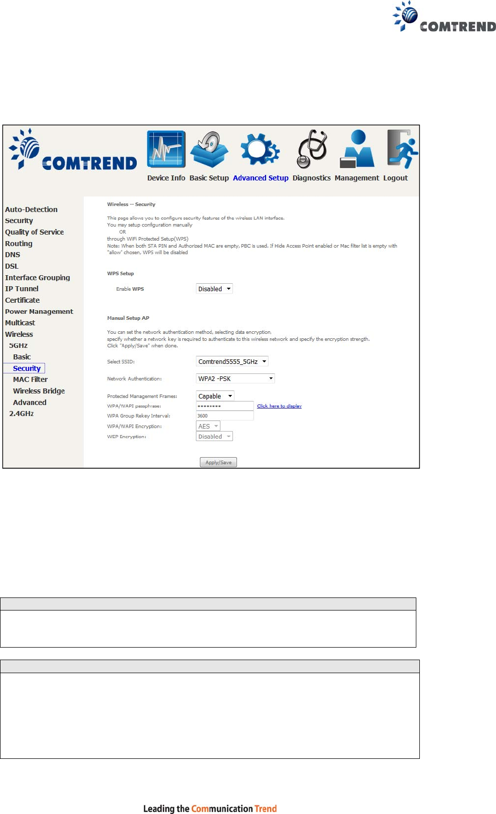
119
6.12.2 Security 5GHz
The following screen appears when Wireless Security is selected. The options shown
here allow you to configure security features of the wireless LAN interface.
Please see 6.12.3 for WPS setup instructions.
Click Apply/Save to implement new configuration settings.
WIRELESS SECURITY
Setup requires that the user configure these settings using the Web User Interface
(see the table below).
Select SSID
Select the wireless network name from the drop-down menu. SSID stands for
Service Set Identifier. All stations must be configured with the correct SSID to
access the WLAN. If the SSID does not match, that client will not be granted access.
Network Authentication
This option specifies whether a network key is used for authentication to the
wireless network. If network authentication is set to Open, then no authentication
is provided. Despite this, the identity of the client is still verified.
Each authentication type has its own settings. For example, selecting 802.1X
authentication will reveal the RADIUS Server IP address, Port and Key fields. WEP
Encryption will also be enabled as shown below.
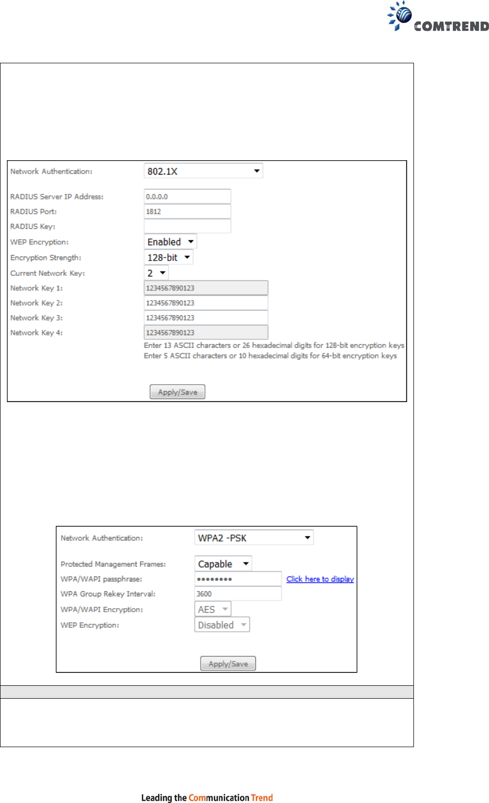
120
Different authentication type pops up different settings requests.
Choosing 802.1X, enter RADIUS Server IP address, RADIUS Port, RADIUS key and
Current Network Key.
Also, enable WEP Encryption and select Encryption Strength.
Select the Current Network Key and enter 13 ASCII characters or 26 hexadecimal
digits for 128-bit encryption keys and enter 5 ASCII characters or 10 hexadecimal
digits for 64-bit encryption keys.
Choosing WPA2-PSK, you must enter WPA Pre-Shared Key and Group Rekey
Interval.
WEP Encryption
This option specifies whether data sent over the network is encrypted. The same
network key is used for data encryption and network authentication. Four network
keys can be defined although only one can be used at any one time. Use the Current
Network Key list box to select the appropriate network key.