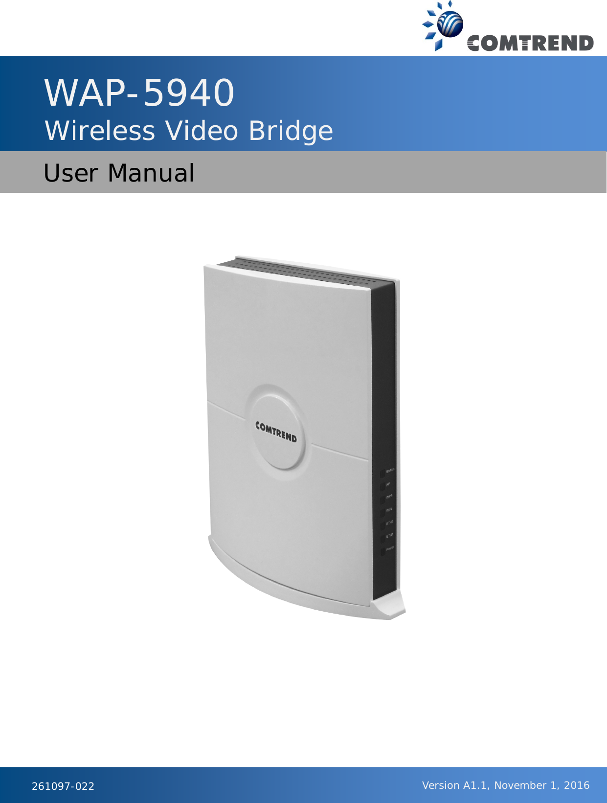
Comtrend WAP-5940 Wireless Video Bridge User Manual CT 5374
Comtrend Corporation Wireless Video Bridge CT 5374
UserManual.wiki
>
Comtrend
>
WAP 5940 User Manual
User manual
Navigation menu
Upload a User Manual
Namespaces
Wiki Guide
HTML
PDF
Info
Views
User Manual
Discussion / Help
Navigation
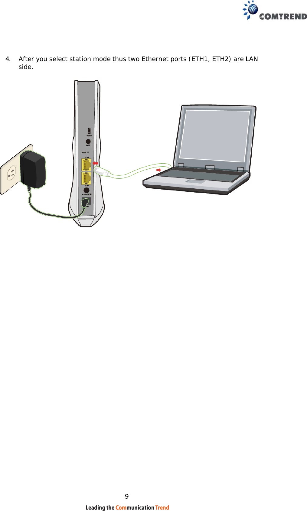
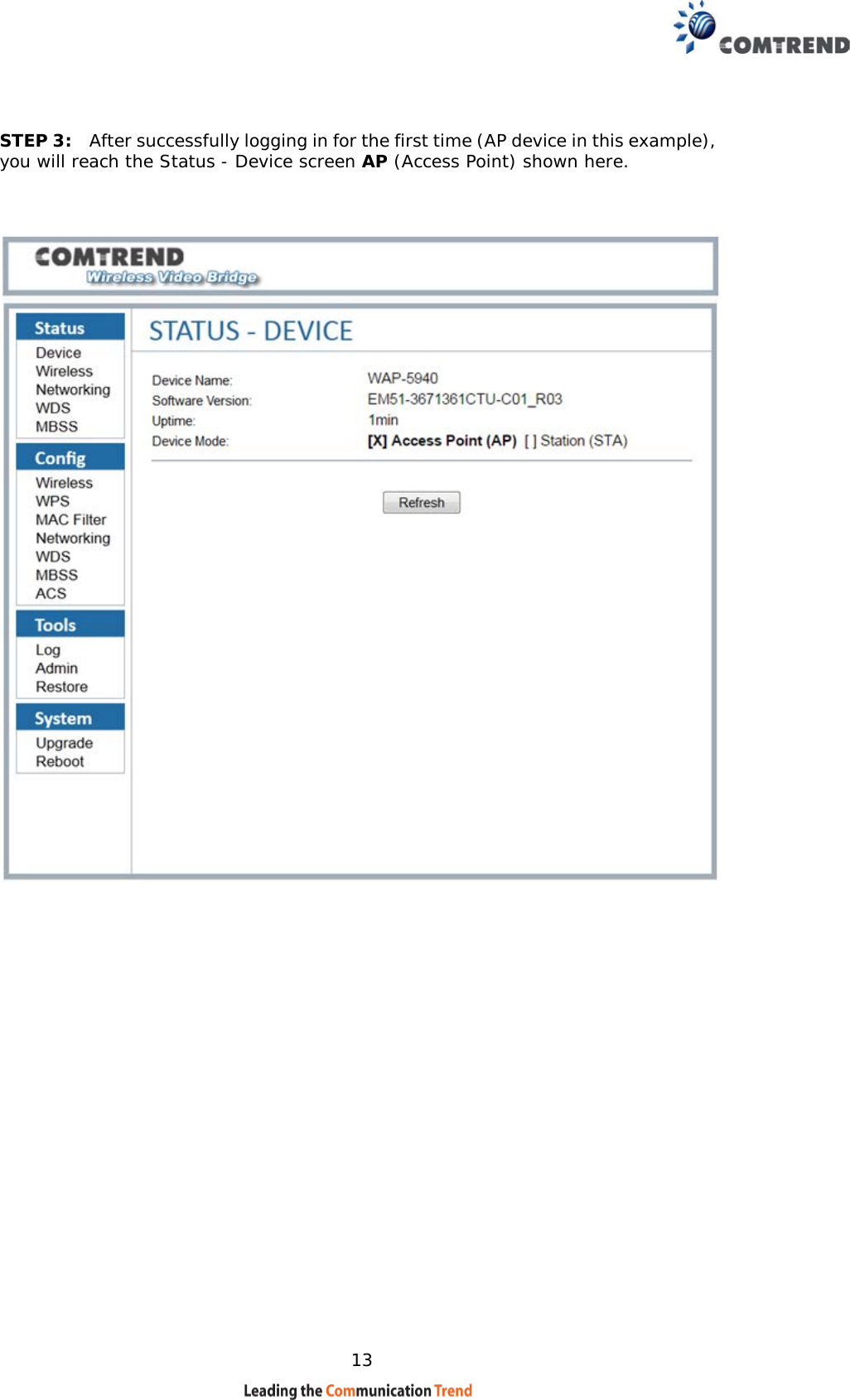
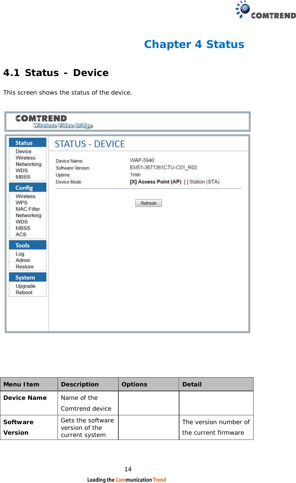
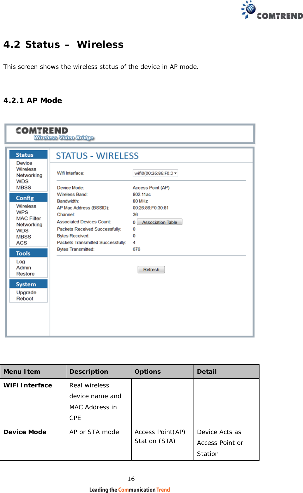
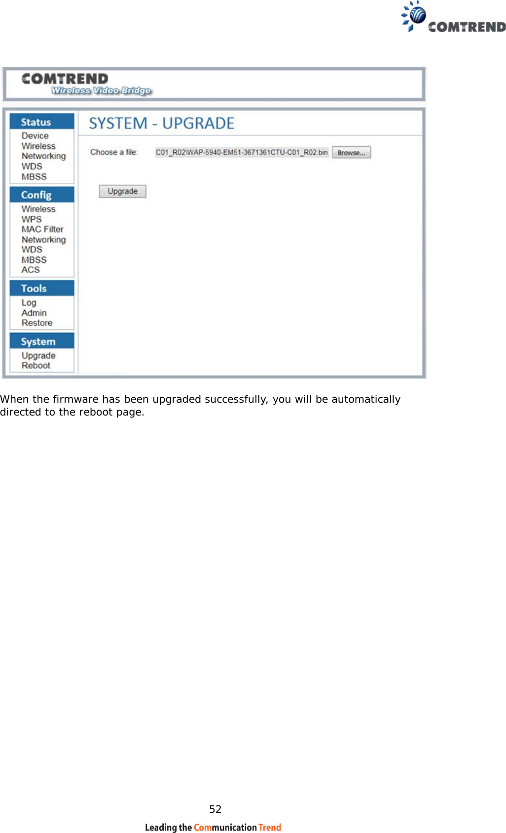
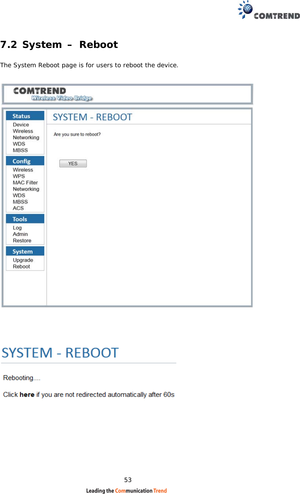
![15 Uptime Displays the uptime of the device There are two types of display, one kind is minutes and days, another kind is XX:XX(hours:minutes) Device Mode AP or STA mode Access Point(AP) Station(STA) Device Acts as Access Point or Station. The [X] indicates the current device mode.](https://usermanual.wiki/Comtrend/WAP-5940/User-Guide-3304496-Page-16.png)