Comtrend WAP-5940 Wireless Video Bridge User Manual CT 5374
Comtrend Corporation Wireless Video Bridge CT 5374
Comtrend >
User manual
261097-022
WAP-5940
Wireless Video Bridge
User Manual
Version A1.1, November 1, 2016

1
Preface
This manual provides information related to the installation and operation of this
device. The individual reading this manual is presumed to have a basic
understanding of telecommunications terminology and concepts.
If you find the product to be inoperable or malfunctioning, please contact technical
support for immediate service by email at INT-support@comtrend.com
For product update, new product release, manual revision, or software upgrades,
please visit our website at http://www.comtrend.com
Important Safety Instructions
With reference to unpacking, installation, use, and maintenance of your electronic
device, the following basic guidelines are recommended:
• Do not use or install this product near water, to avoid fire or shock hazard. For
example, near a bathtub, kitchen sink or laundry tub, or near a swimming pool.
Also, do not expose the equipment to rain or damp areas (e.g. a wet basement).
• Do not connect the power supply cord on elevated surfaces. Allow it to lie freely.
There should be no obstructions in its path and no heavy items should be placed
on the cord. In addition, do not walk on, step on, or mistreat the cord.
• Use only the power cord and adapter that are shipped with this device.
• To safeguard the equipment against overheating, make sure that all openings in
the unit that offer exposure to air are not blocked.
• Avoid using a telephone (other than a cordless type) during an electrical storm.
There may be a remote risk of electric shock from lightening. Also, do not use
the telephone to report a gas leak in the vicinity of the leak.
• Never install telephone wiring during stormy weather conditions.
CAUTION:
To reduce the risk of fire, use only No. 26 AWG or larger
telecommunication line cord.
Always disconnect all telephone lines from the wall outlet before servicing
or disassembling this equipment.
WARNING
Disconnect the power line from the device before servicing.
Power supply specifications are clearly stated in Appendix A -
Specifications.
2
Copyright
Copyright©2016 Comtrend Corporation. All rights reserved. The information
contained herein is proprietary to Comtrend Corporation. No part of this document
may be translated, transcribed, reproduced, in any form, or by any means without
prior written consent of Comtrend Corporation.
This program is free software: you can redistribute it and/or modify it under the
terms of the GNU General Public License as published by the Free Software
Foundation, either version 3 of the License, or (at your option) any later version.
This program is distributed in the hope that it will be useful, but WITHOUT ANY
WARRANTY; without even the implied warranty of MERCHANTABILITY or FITNESS
FOR A PARTICULAR PURPOSE. See the GNU General Public License for more
details.
You should have received a copy of the GNU General Public License
along with this program. If not, see http://www.gnu.org/licenses/
NOTE: This document is subject to change without notice.
This program is free software: you can redistribute it and/or modify it
under the terms of the GNU General Public Li
Protect Our Environment
This symbol indicates that when the equipment has reached the end of
its useful life, it must be taken to a recycling centre and processed
separate from domestic waste.
The cardboard box, the plastic contained in the packaging, and the parts that make
up this router can be recycled in accordance with regionally established regulations.
Never dispose of this electronic equipment along with your household waste; you
may be subject to penalties or sanctions under the law. Instead, please be
responsible and ask for disposal instructions from your local government.

3
Table of Contents
CHAPTER 1 INTRODUCTION ........................................................................................................... 4
CHAPTER 2 INSTALLATION ............................................................................................................. 5
2.1 HARDWARE SETUP ........................................................................................................................... 5
2.2 LED INDICATORS............................................................................................................................. 7
2.3 INITIAL DEVICE SETUP .................................................................................................................... 8
CHAPTER 3 WEB USER INTERFACE............................................................................................ 10
3.1 DEFAULT SETTINGS ....................................................................................................................... 10
3.2 IP CONFIGURATION ........................................................................................................................ 11
3.3 LOGIN PROCEDURE ........................................................................................................................ 12
CHAPTER 4 STATUS .......................................................................................................................... 14
4.1 STATUS - DEVICE ........................................................................................................................... 14
4.2 STATUS – WIRELESS ................................................................................................................ 16
4.2.1 AP Mode ................................................................................................................................ 16
4.2.2 STA Mode ............................................................................................................................... 19
4.3 STATUS – NETWORKING ................................................................................................................. 22
4.4 STATUS – WDS .............................................................................................................................. 24
4.5 STATUS – MBSS ............................................................................................................................ 25
CHAPTER 5 CONFIG ......................................................................................................................... 27
5.1 CONFIG – WIRELESS ...................................................................................................................... 27
5.2 CONFIG – WPS .............................................................................................................................. 32
5.3 CONFIG – MAC FILTER ................................................................................................................. 34
5.4 CONFIG – NETWORKING ................................................................................................................ 36
5.5 CONFIG – WDS ............................................................................................................................. 39
5.6 CONFIG – MBSS ............................................................................................................................ 41
5.7 CONFIG – ACS ............................................................................................................................... 42
CHAPTER 6 TOOLS ........................................................................................................................... 46
6.1 TOOLS – LOG ................................................................................................................................. 46
6.2 TOOLS – ADMIN ............................................................................................................................. 49
6.3 TOOLS – RESTORE ......................................................................................................................... 50
CHAPTER 7 SYSTEM ........................................................................................................................ 51
7.1 SYSTEM – UPGRADE ...................................................................................................................... 51
7.2 SYSTEM – REBOOT ........................................................................................................................ 53
APPENDIX A - SPECIFICATIONS ................................................................................................... 54
APPENDIX B - AP / STATION ........................................................................................................... 55

4
Chapter 1 Introduction
The WAP-5940 is an 802.11ac 4T4R wireless video bridge, with two Giga Ethernet
ports. WAP-5940 performs AP to transmission package TCP/UDP to client, also
supporting station mode, receiving packets and forwarding to the Ethernet port.
WAP-5940 has a high power wireless design which supports 802.11ac 5Ghz band
4T4R and is backward compatible 802.11n, 802.11a.

5
Chapter 2 Installation
2.1 Hardware Setup
Follow the instructions below to complete the hardware setup.
BACK PANEL
The figure below shows the back panel of the device.

6
Power ON
Press the power button to the OFF position (OUT). Connect the power adapter to the
power port. Attach the power adapter to a wall outlet or other AC source. Press the
power button to the ON position (IN). If the Power LED displays as expected then
the device is ready for setup (see section 2.2 LED Indicators).
Caution 1: If the device fails to power up, or it malfunctions, first verify that the
power cords are connected securely and then power it on again. If the
problem persists, contact technical support.
Caution 2: Before servicing or disassembling this equipment, disconnect all power
cords and telephone lines from their outlets.
Ethernet (LAN) Ports
Use 1000-BASE-T RJ-45 cables to connect two network devices to a Gigabit LAN, or
10/100BASE-T RJ-45 cables for standard network usage. These ports are
auto-sensing MDI/X; so either straight-through or crossover cable can be used.
Reset Button
To reboot the device press the Reset button for 1-5 seconds. Restore the default
parameters of the device by pressing the Reset button for more than 5 seconds.
After the device has rebooted successfully, the front panel should display as
expected (see section 2.2 LED Indicators for details).
WPS Button
Press and release the WPS button to start the WPS connection process with the
other device. The connection duration is 2 minutes during which the WPS LED will
blink. If there is no client connection the WPS led will turn off. If connection is
successful the WPS LED will stay on.
AP/Station Switch
Select the desired option.

7
2.2 LED Indicators
The front panel LED indicators are shown below and explained in the following table.
This information can be used to check the status of the device and its connections.
LED Color Mode Description
POWER GREEN On Power on
Off Power off
ETH1 GREEN
On
Ethernet connected
Off
Ethernet not connected
Blink
Ethernet is transmitting/receiving
ETH2 GREEN
On
Ethernet connected
Off
Ethernet not connected
Blink
Ethernet is transmitting/receiving
WiFi GREEN
On
Wi-Fi enabled
Off
Wi-Fi disabled
Blink
When no client connected
WPS GREEN
On WPS connection successful
Off
No WPS (5G) association process ongoing
Blink
WPS (5G) connection in progress
AP GREEN On
WAP-5940 working in AP mode
Off
WAP-5940 working in Station mode
Station GREEN On
WAP-5940 working in Station mode
Off
WAP-5940 working in AP mode
8
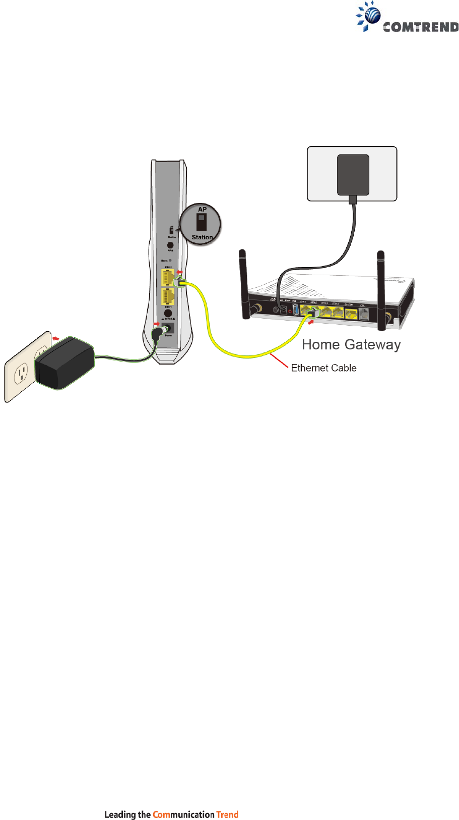
2.3 Initial Device Setup
Device Setup
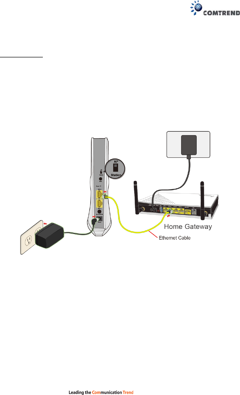
1. Setup the first Wireless Video Bridge by plugging in the power adapter and
press the Power Button to the ON position (IN). Set the Wireless Video
Bridge to AP Mode by sliding the AP/Station Switch to the up position.
2. Connect the Wireless Video Bridge to a Network Device (Gateway, Router,
etc.) with an Ethernet (RJ-45) cable. You can use either Ethernet ports of the
Wireless Video Bridge to make this connection.
3. After you select AP mode thus the Ethernet port (ETH1) will be WAN port,
another Ethernet port (ETH2) is LAN side.
9
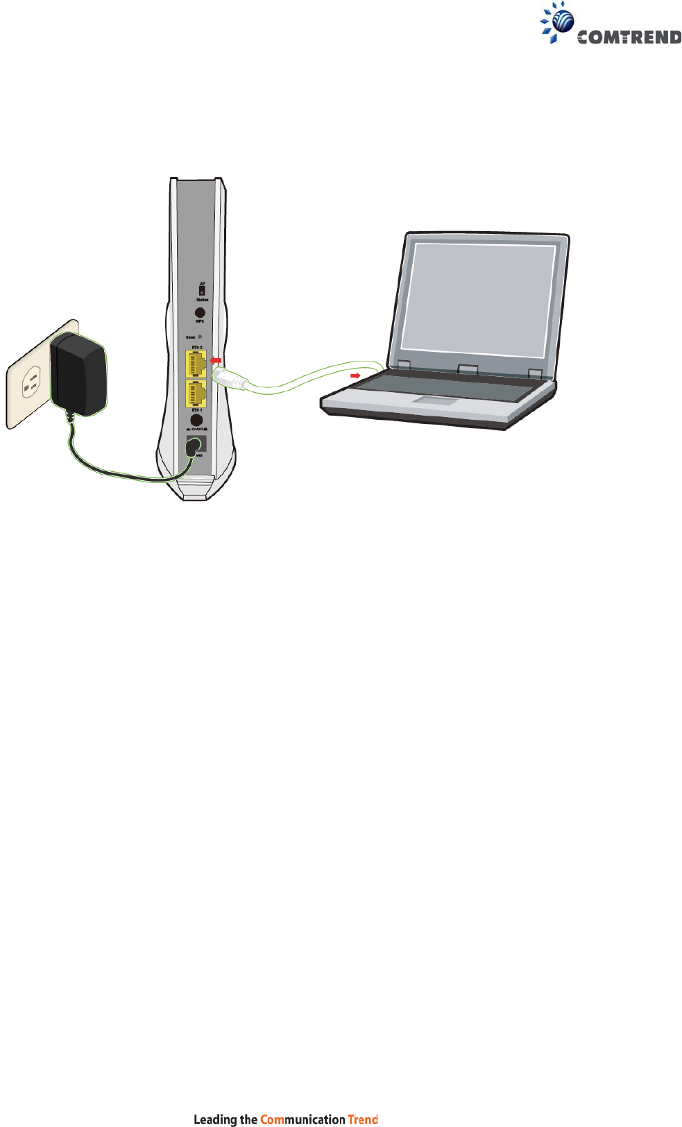
4. After you select station mode thus two Ethernet ports (ETH1, ETH2) are LAN
side.

10
Chapter 3 Web User Interface
This section describes how to access the device via the web user interface (WUI)
using an Internet browser such as Internet Explorer (version 6.0 and later).
3.1 Default Settings
The factory default settings of this device are summarized below.
• LAN IP address AP: 10.0.0.2
• LAN IP address STA: 10.0.0.10
• LAN subnet mask: 255.255.255.0
• Administrative access (username: root, password: 12345)
Caution: The LAN setting default is DHCP mode, if a device connects to the DHCP
network, the LAN IP will be changed by the DHCP server assigned.
Technical Note
During power on, the device initializes all settings to default values. It will then
read the configuration profile from the permanent storage section of flash memory.
The default attributes are overwritten when identical attributes with different values
are configured. The configuration profile in permanent storage can be created via
the web user interface or telnet user interface, or other management protocols.
The factory default configuration can be restored either by pushing the reset button
for more than ten seconds until the power indicates LED blinking or by clicking the
Restore Default Configuration option in the Restore Settings screen.
11
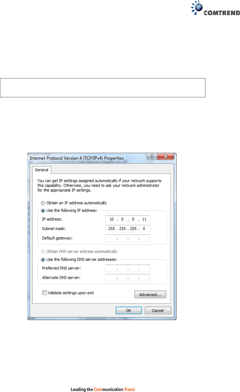
3.2 IP Configuration
STATIC IP MODE
In static IP mode, you assign IP settings to your PC manually.
Follow these steps to configure your PC IP address to use subnet 10.0.0.x.
NOTE: The following procedure assumes you are running Windows. However,
the general steps involved are similar for most operating systems (OS).
Check your OS support documentation for further details.
STEP 1: From the Network Connections window, open Local Area Connection (You
may also access this screen by double-clicking the Local Area Connection
icon on your taskbar). Click the Properties button.
STEP 2: Select Internet Protocol (TCP/IP) and click the Properties button.
STEP 3: Change the IP address to the 10.0.0.x (10<x<254) subnet with subnet
mask of 255.255.255.0. The screen should now display as shown below.
STEP 4: Click OK to submit these settings.
12
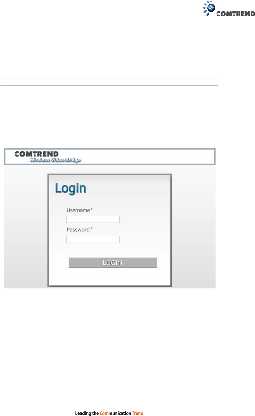
3.3 Login Procedure
Perform the following steps to login to the web user interface.
NOTE: The default settings can be found in section 3.1 Default Settings.
STEP 1: Start the Internet browser and enter the default IP address for the device
in the Web address field. For example, if it is the AP device default IP is
10.0.0.2, type http://10.0.0.2
STEP 2: A dialog box will appear, such as the one below. Enter the default
username and password, as defined in section 3.1 Default Settings.
Click LOGIN to continue.
13
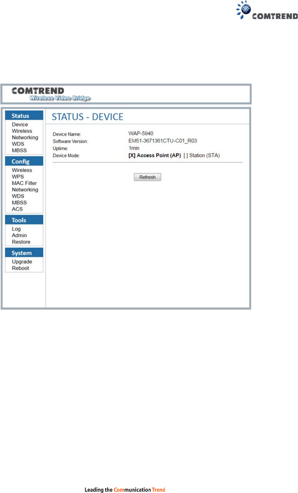
STEP 3: After successfully logging in for the first time (AP device in this example),
you will reach the Status - Device screen AP (Access Point) shown here.
14
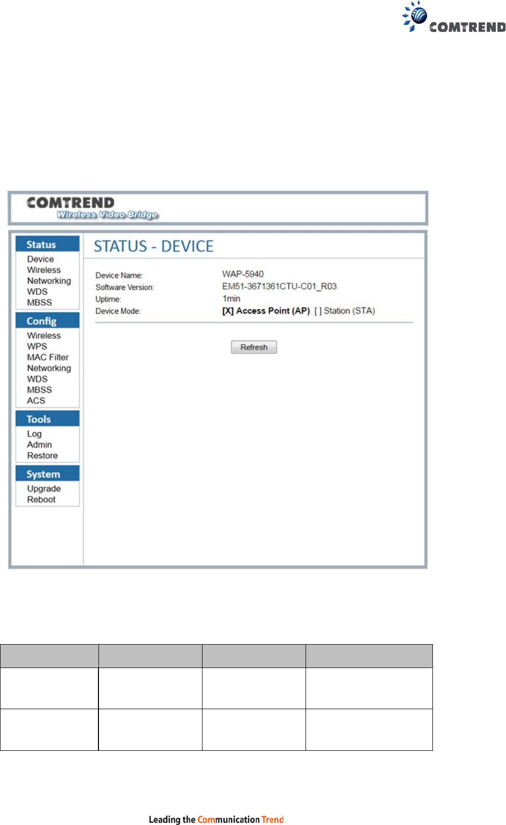
Chapter 4 Status
4.1 Status - Device
This screen shows the status of the device.
Menu Item Description Options Detail
Device Name Name of the
Comtrend device
Software
Version
Gets the software
version of the
current system
The version number of
the current firmware

15
Uptime Displays the
uptime of the
device
There are two types of
display, one kind is
minutes and days,
another kind is
XX:XX(hours:minutes)
Device Mode AP or STA mode Access Point(AP)
Station(STA) Device Acts as Access
Point or Station. The
[X] indicates the
current device mode.
16
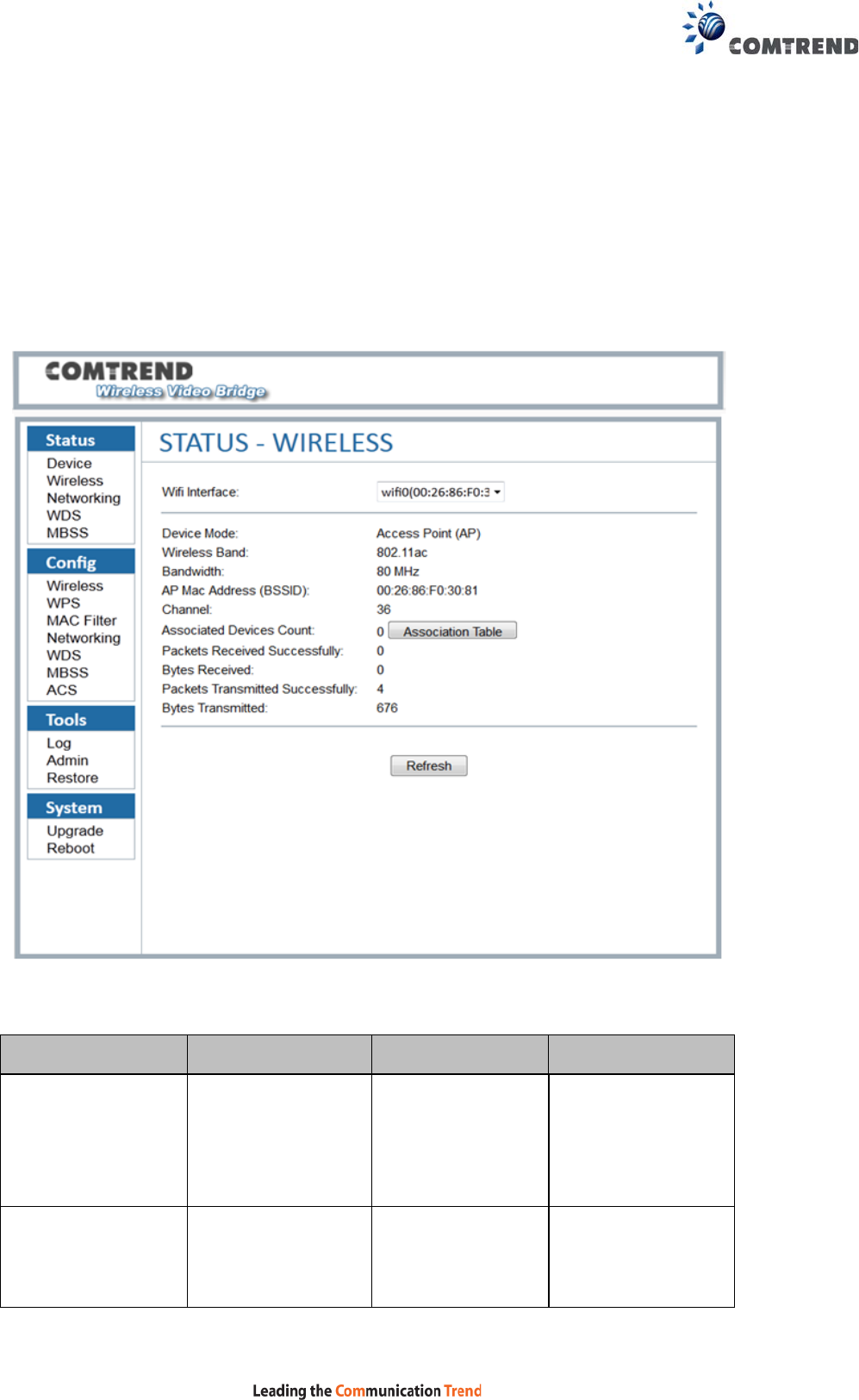
4.2 Status – Wireless
This screen shows the wireless status of the device in AP mode.
4.2.1 AP Mode
Menu Item Description Options Detail
WiFi Interface Real wireless
device name and
MAC Address in
CPE
Device Mode
AP or STA mode
Access Point(AP)
Station (STA) Device Acts as
Access Point or
Station

17
Wireless Band
Current system
Band
802.11a or
802.11an or
802.11ac
802.11an supports
802.11n and is
backward
compatible with
802.11a
Bandwidth Per the 802.11a or
802.11an or
802.11ac standard
20 MHz
20 MHz operation
Per 802.11an or
802.11ac standard
40 MHz 40 MHz operation
Per the 802.11ac
standard
80MHz 80 MHz operation
AP Mac Address
(BSSID)
The current
associated BSSID
of the Wi-Fi system
In AP mode, it will
be the same as the
Wireless MAC
address
Channel Available 5Ghz
channels based on
region setting
36-48, 149-165 5.150-5.250,
5.725-5.850 GHz
are the supported
frequency ranges
Associated
Devices Count
The connected
devices number
The number of
devices connecting
to the AP.
Clicking the
“Association Table”
will link to the
Association Table
page and display
information of all
the connected
devices.
Packets Received
Successfully
Wireless packets
which are received
successfully
Bytes Received The total bytes
received
successfully
18
Packets
Transmitted
Successfully
Wireless packets
transmitted
Bytes
Transmitted
Total bytes
transmitted
successfully
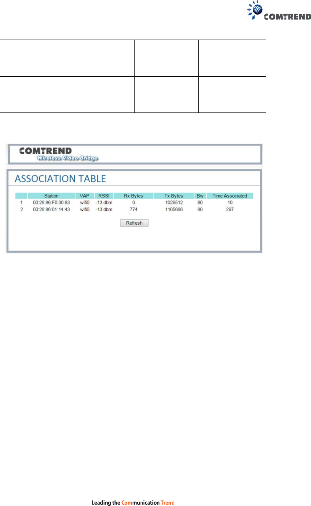
This screen shows the information of all station devices which are connecting with
the wifi0 of the AP.
19
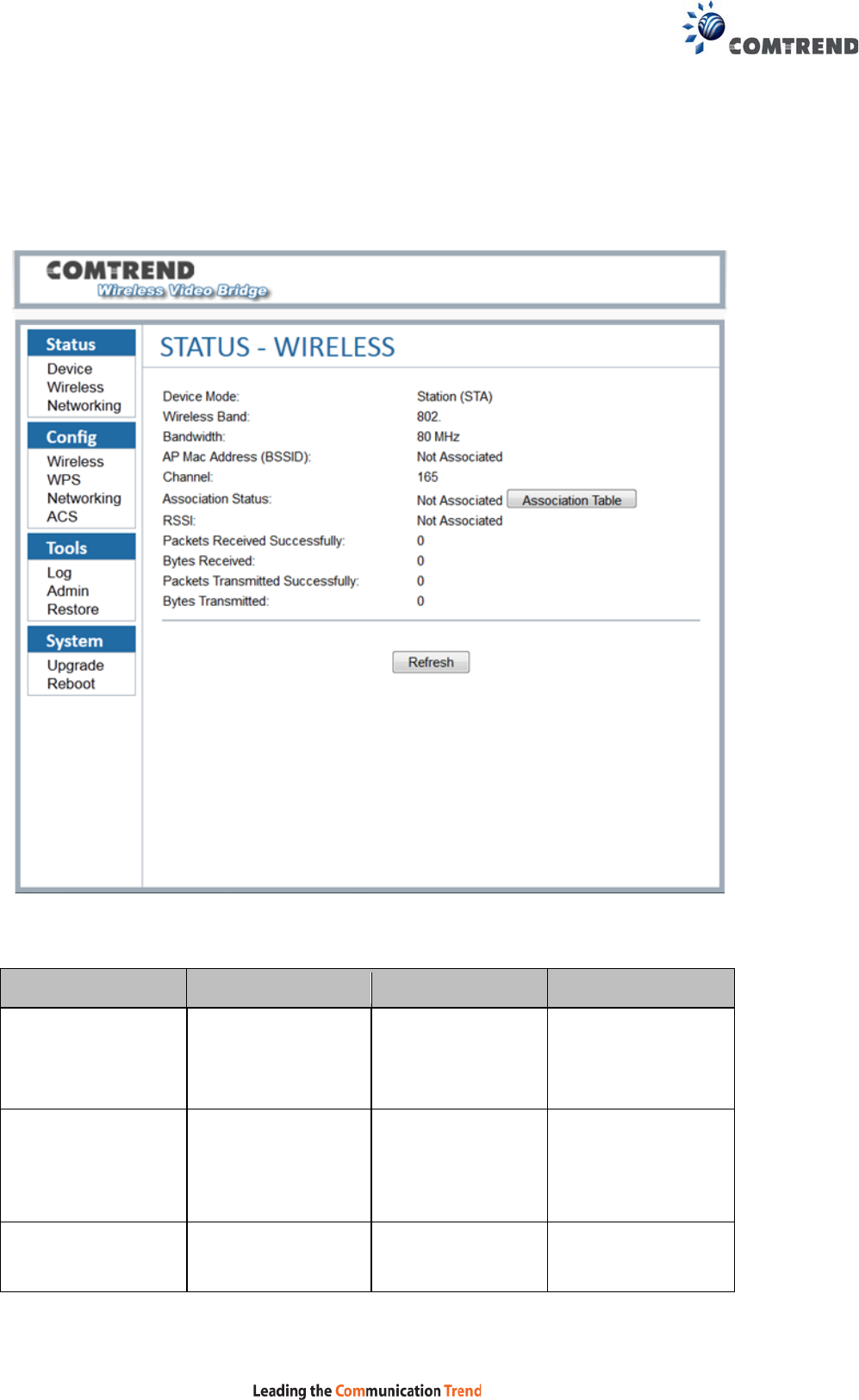
4.2.2 STA Mode
This screen shows the wireless status of the device that acts as a STA.
This STA mode is mainly with other client bridge, Not directly used as a client.
Menu Item Description Options Detail
Device Mode
AP or STA mode
Access Point(AP)
Station (STA) Device Acts as
Access Point or
Station
Wireless Band
Current system
Band
802.11a or
802.11an or
802.11ac
802.11an supports
802.11n and is
backward
compatible with
802.11a
Bandwidth Per the 802.11a
or
802.11an or
20 MHz
20 MHz operation

20
802.11ac standard
Per 802.11an or
802.11ac standard
40 MHz 40 MHz operation
Per the 802.11ac
standard
80MHz 80 MHz operation
AP Mac Address
(BSSID)
The current
associated BSSID
of the Wi-Fi system
In AP mode, it will
be the same as the
Wireless MAC
address
Channel Available 5Ghz
channels based on
region setting
36-48, 149-165 5.150-5.250,
5.725-5.850 GHz
are the supported
frequency ranges
Association
Status
The connected
devices number
The number of
devices connecting
to the AP.
Clicking the
“Association Table”
will link to the
Association Table
page and display
information of all
the connected
devices.
RSSI Received Signal
Strength Indication
A measurement of
the power present
in a received radio
signal. The value is
the current RSSI in
dBm for the
association.
Packets Received
Successfully
Wireless packets
which are received
successfully

21
Bytes Received The total bytes
received
successfully
Packets
Transmitted
Successfully
Wireless packets
transmitted
Bytes
Transmitted
Total bytes
transmitted
successfully
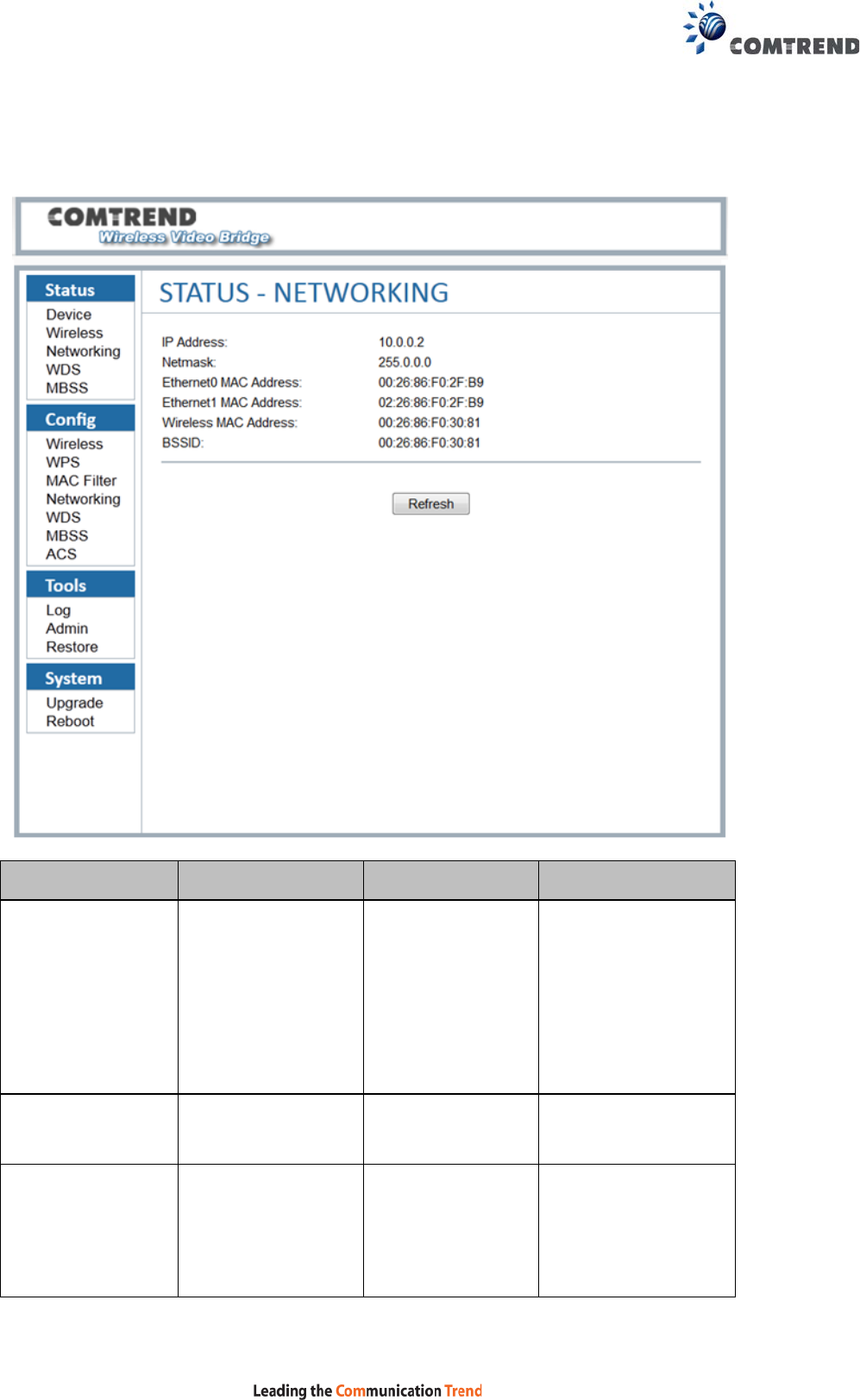
22
4.3 Status – Networking
This screen shows the status of the networking.
Menu Item Description Options Detail
IP Address The IP Address of
the system
Logged into the web
GUI with this IP
address. It can be
changed in the
Config Networking
page.
Netmask The netmask of the
IP address
Ethernet MAC
Address
This is the IEEE
compliant MAC
address of the
Ethernet interface
The internal network
bridge uses this MAC
address

23
Wireless MAC
Address
This is the IEEE
compliant MAC
address of the
Wi-Fi interface
The WLAN MAC
address
BSSID The current
associated BSSID
of the Wi-Fi system
In AP mode: this will
be the SAME as the
Wireless MAC
address.
In STA mode and
associated to an AP:
this will be the value
of the AP’s MAC
address.
If the STA is not
associated, this will
state:
“Not-Associated”.
24
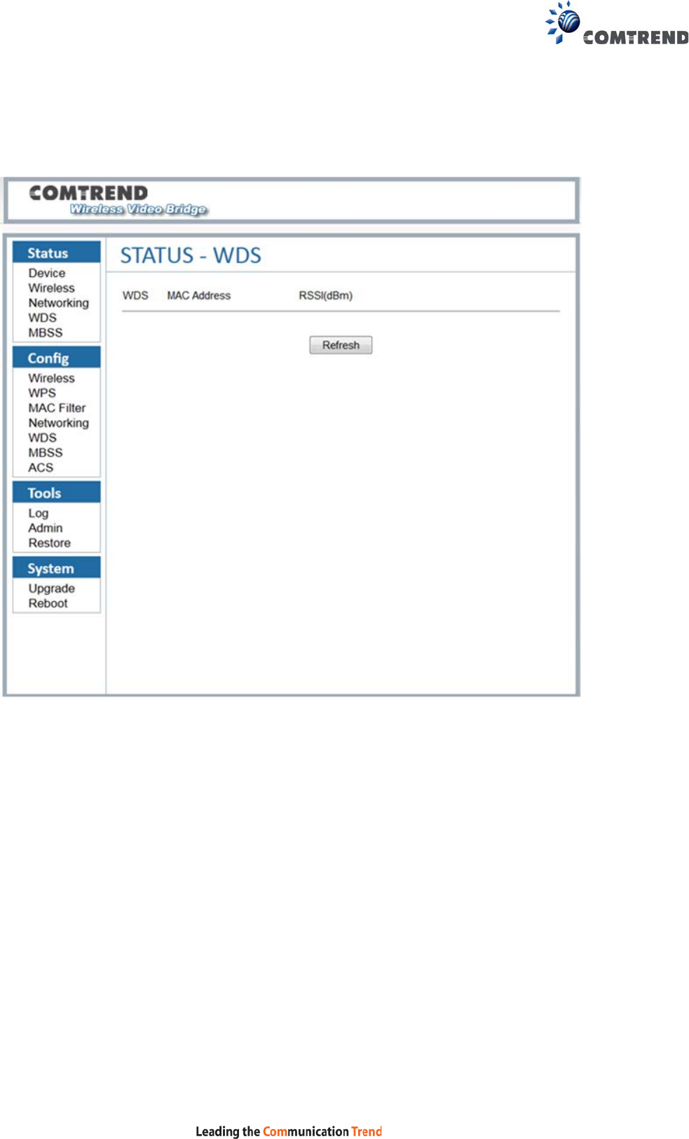
4.4 Status – WDS
This screen shows the status of the WDS links.
This typical WDS link status includes:
• The interface name of the WDS link, the name is managed by the system
automatically, usually it is: WDS0/WDS1/WDS2…so on.
• The WDS peer MAC address of the opposite side, this MAC address is same
as the address which you are using when creating WDS links.
• The WDS link quality.
25
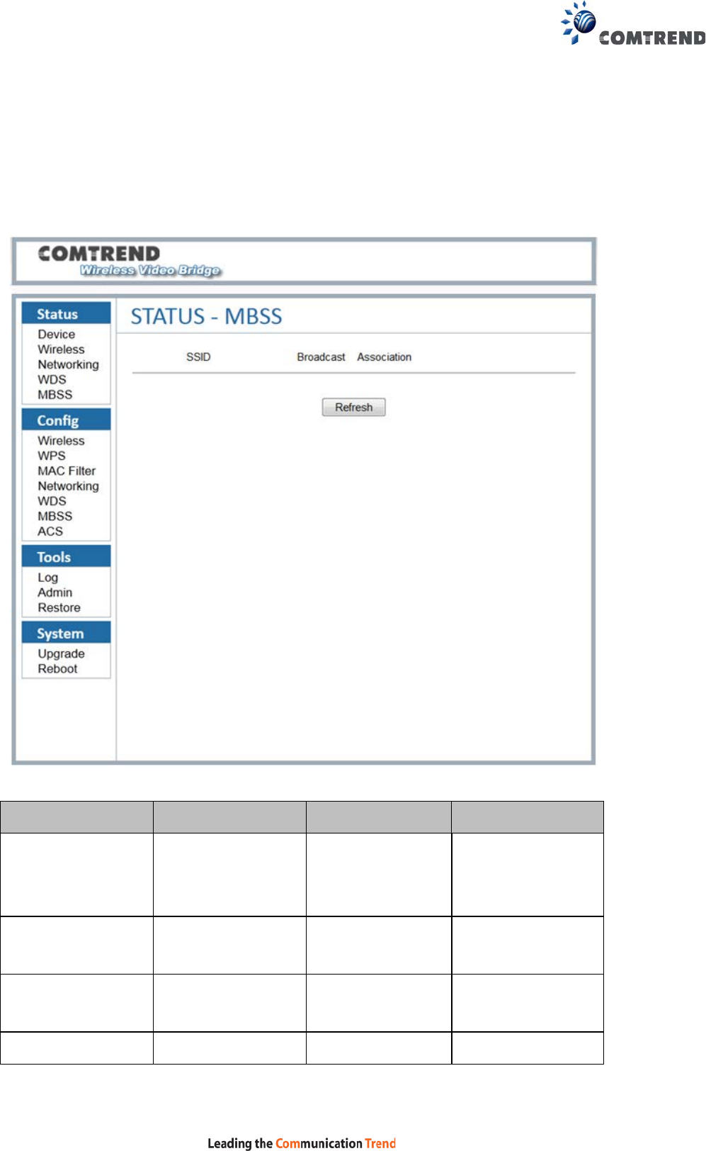
4.5 Status – MBSS
Displays the information of multiple Basic Service Set Identifiers (BSSIDs) created
on the device: SSID, Broadcast, Association count and details of the station
connected. This option is not available if the device is configured as a STA. For
instructions on setting up WAP-5940 as a WDS using AP mode, please refer to Appendix B.
Menu Item Description Options Detail
SSID SSID of the MBSS
This will be the
SSID of the
wireless network.
Broadcast
Enabled or disabled
SSID broadcast
TRUE
SSID will be
broadcasted
FALSE Wi-Fi devices can’t
scan out this SSID
Association Associated client >=0 The number of

26
number client which are
connected to the
Virtual AP
27
Chapter 5 Config
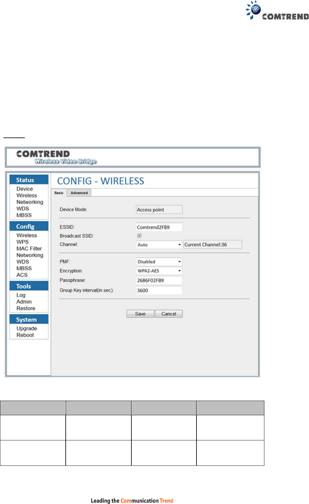
5.1 Config – Wireless
This screen has two tab pages, “Basic” and “Advanced”.
Basic
Menu Item Description Options Detail
Device Mode
AP or STA mode
Access Point
Device Acts as
Access Point
Station Device Acts as
Station

28
ESSID SSID of the AP Can be set to
desired SSID
name
This will be the
SSID of the
wireless network.
Channel Available 5Ghz
channels based on
region setting
36-48, 149-165 5.150-5.250,
5.725-5.850 GHz
are the supported
frequency ranges
PMF Protected
Management
Frames
Sets the 802.11w /
PMF capability.
Applies to AP
Encryption 802.11 compliant
authentication and
encryption
WPA2/AES
NONE-OPEN Disables encryption
(OPEN mode)
WPA2 + WPA
(Mixed mode)
WPA2/AES
Enterprise
WPA2 + WPA
Enterprise
Passphrase The current
passphrase.
Applies to AP only.
Group Key
interval(in sec)
Group key renewal
interval for
enterprise security
Group key interval
needs to be
between 0 and
43200
This is the interval
at which the group
key is renewed for
clients associated
to this SSID
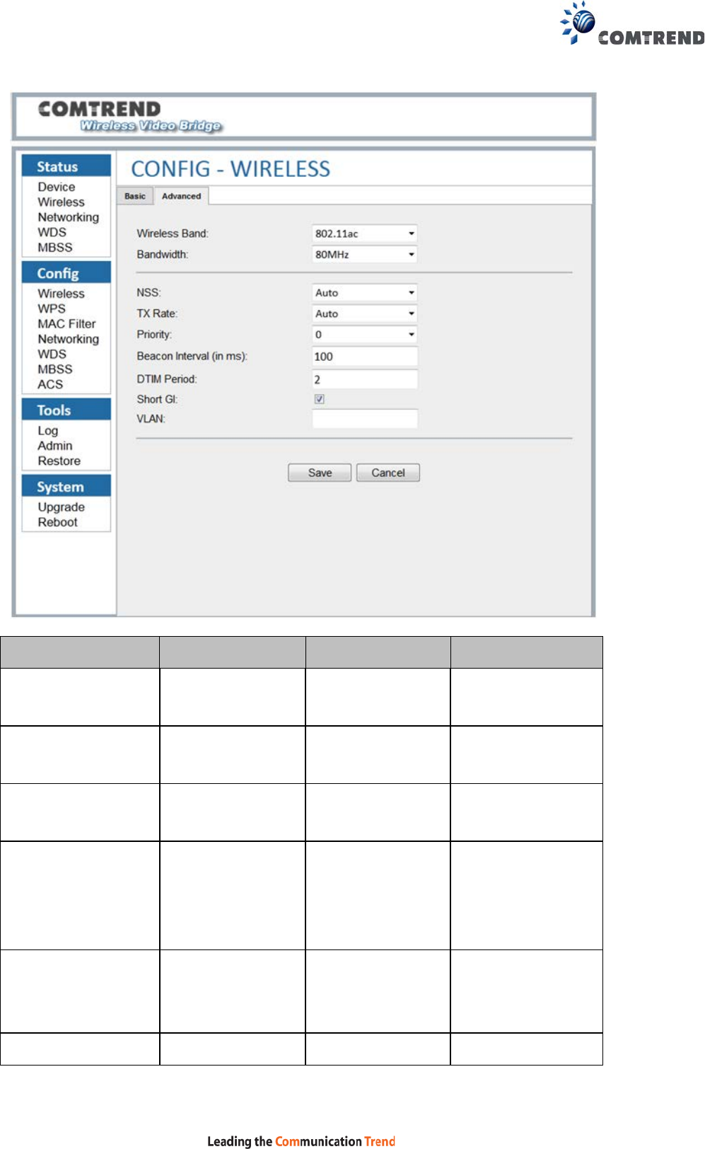
Advanced
29
Menu Item Description Options Detail
Wireless Band Frequency Band to
be used
802.11a
802.11a 5 GHz
operation
802.11an 802.11an 5 GHz
operation
802.11ac 802.11ac 5 GHz
operation
Bandwidth Per the 802.11a or
802.11an or
802.11ac
standard
20 MHz
20 MHz operation
Per the 802.11an
or 802.11ac
standard
40 MHz 40 MHz operation
Per the 802.11ac 80MHz 80 MHz operation

30
standard
NSS The maximum
number of spatial
streams
Auto
1
2
3
4
Tx Rate Transmitted data
rate
Not supported for
802.11a standard
Auto or MCS0
~MCS76 for
802.11an
standard
Auto Rate Control,
MCS 0-76
Only Auto option
available for
802.11ac
standard when
NSS is set to Auto.
When NSS is not
set to Auto,
MCS0~MCS9
options are
available.
Priority The priority is
used to
differentiate
traffic between
different
SSIDs
0~3
Beacon Interval Set the interval of
the beacon
How often the
device sends a
Beacon. The
interval should be
between 25 and
5000. The default
value is 100.
DTIM Period
Delivery Traffic
Indication
Message
The DTIM period
indicates how often
clients serviced by
the access point

31
should check for
buffered data
awaiting pickup on
the access point.
The value should
between 1 and 15.
Short GI Guard Intervals Checked The 802.11n draft
specifies two guard
intervals: 400ns
(short) and 800ns
(long).
The GI is 400ns.
VLAN Virtual Lan for
different interface
1-4096
32
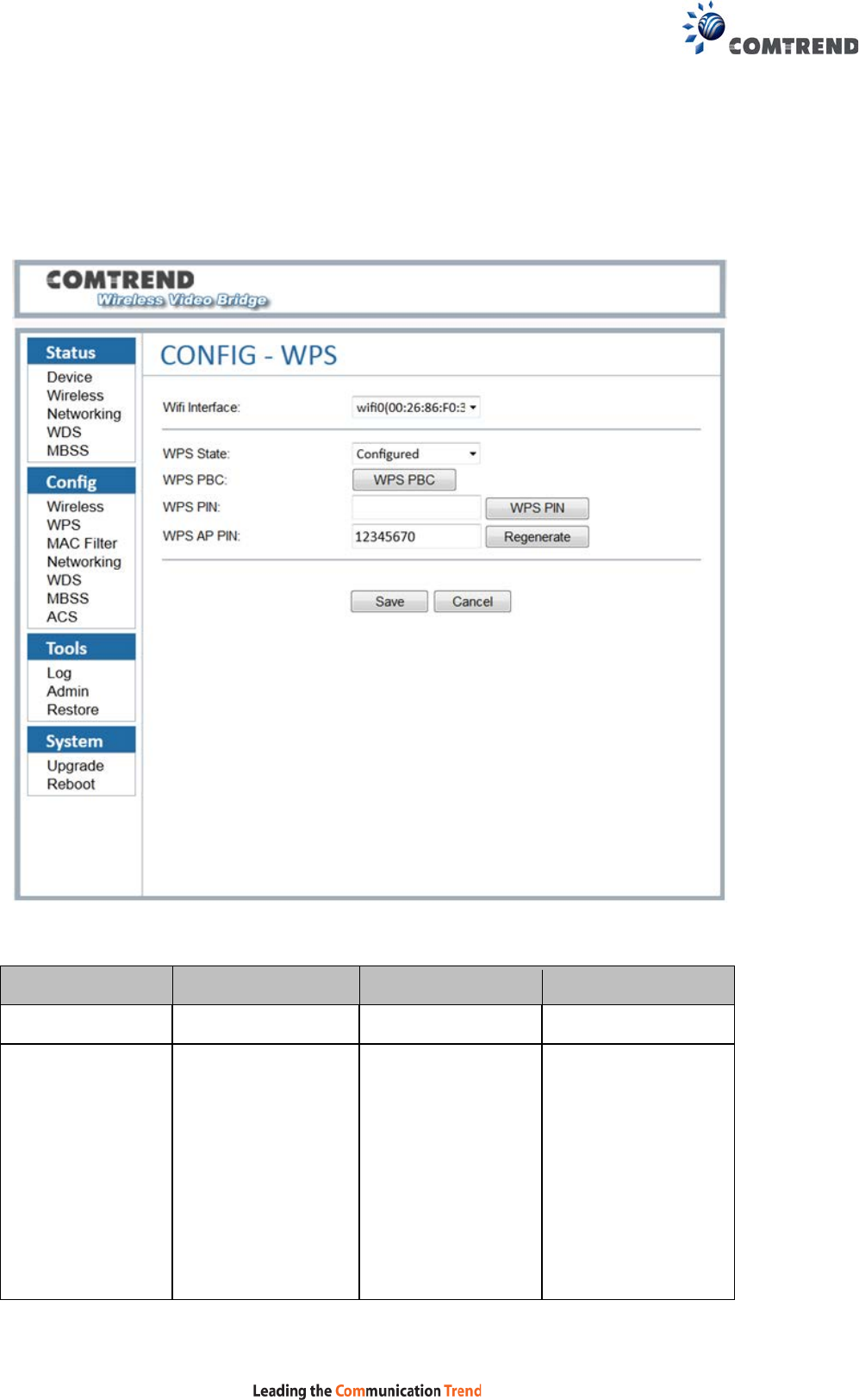
5.2 Config – WPS
Connect to without selecting an SSID and inputting a Passphrase.
Menu Item Description Options Detail
WPS State Set WPS states Disabled WPS disabled
Not configured WPS enabled
User can remotely
change AP's
wireless
settings…SSID,
Encryption and
Passphrase for
example.

33
Configured User needs to fill
certain parameters
to start WPS
connection
WPS PBC WPS push button Push button to start
WPS connection
WPS PIN For Web UI pin
WPS pin mode
Character string
This will be the PIN
used for Web UI
WPS pin mode.
WPS AP PIN Client must have
same PIN within 2
minutes. It is
recommended to
use the external
WPS push button on
the device.
34
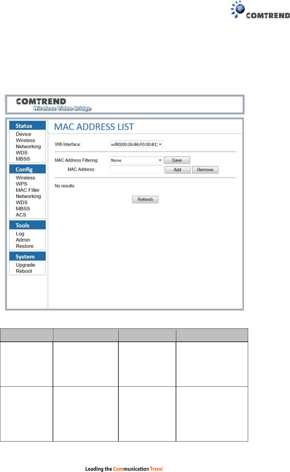
5.3 Config – MAC Filter
This screen shows the MAC addresses filtering configurations that are used for the
AP.
Menu Item Description Options Detail
Wifi Interface Real wireless device
name and MAC
Address in CPE
MAC Address
Filtering
The device filter
MAC address
NONE The AP can block a
selected station from
associating based on
its MAC (hardware
interface) address.

35
“NONE”= Disable MAC
address filtering.
White list mode Accept a client
association request
unless the MAC
address for that client
has been blocked
Black list mode
Block a client
association request
unless the MAC
address for that client
has been authorized
MAC Address Verify the MAC
address
Checks whether the
MAC address can be
validated
MAC Address
List
List the authorized
or denied MAC
addresses
According to the MAC
address filter
“Authorize if not
denied” filter lists the
denied MAC
addresses.
“Deny if not
authorized” filter lists
the authorized MAC
addresses.
36
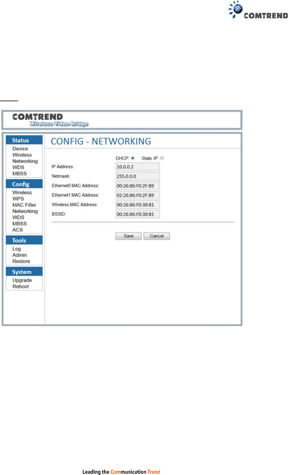
5.4 Config – Networking
These screens show the networking configuration.
DHCP
37
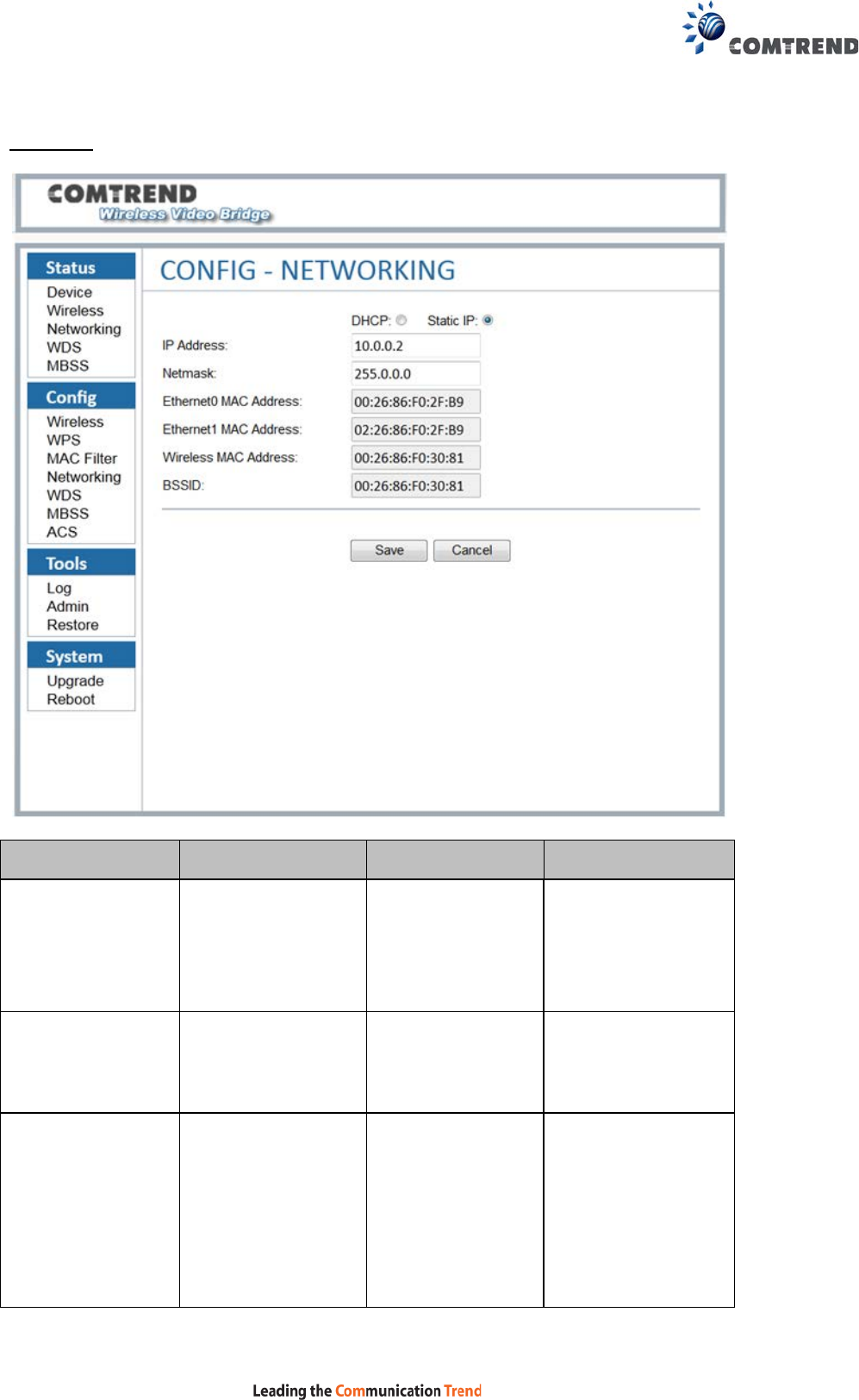
Static IP
Menu Item Description Options Detail
DHCP or Static
IP
Set the network
configuration to
DHCP or Static IP
DHCP
The device will try
to get its IP address
with DHCP from a
device like a router
Static IP The device will use
the static IP
address
IP Address
The IP Address of
the system
This can be
changed from this
interface, by editing
this field.
If the device is
using DHCP, the IP

38
address is not
allowed to change.
CAUTION: After
selecting “Save”,
the IP Address will
change
IMMEDIATELY. The
Web UI must be
pointed at the new
address in order to
continue your Web
UI Session.
Netmask Netmask of the IP
address
Ethernet MAC
Address
This is the IEEE
compliant MAC
address of the
Ethernet interface
The internal
network bridge
uses this MAC
address. This
cannot be changed.
Wireless MAC
Address
This is the IEEE
compliant MAC
address of the
Wi-Fi interface.
The WLAN MAC
address. This
cannot be changed.
BSSID The current
associated BSSID
of the Wi-Fi
system.
this will be the
SAME as the
Wireless MAC
address.
39
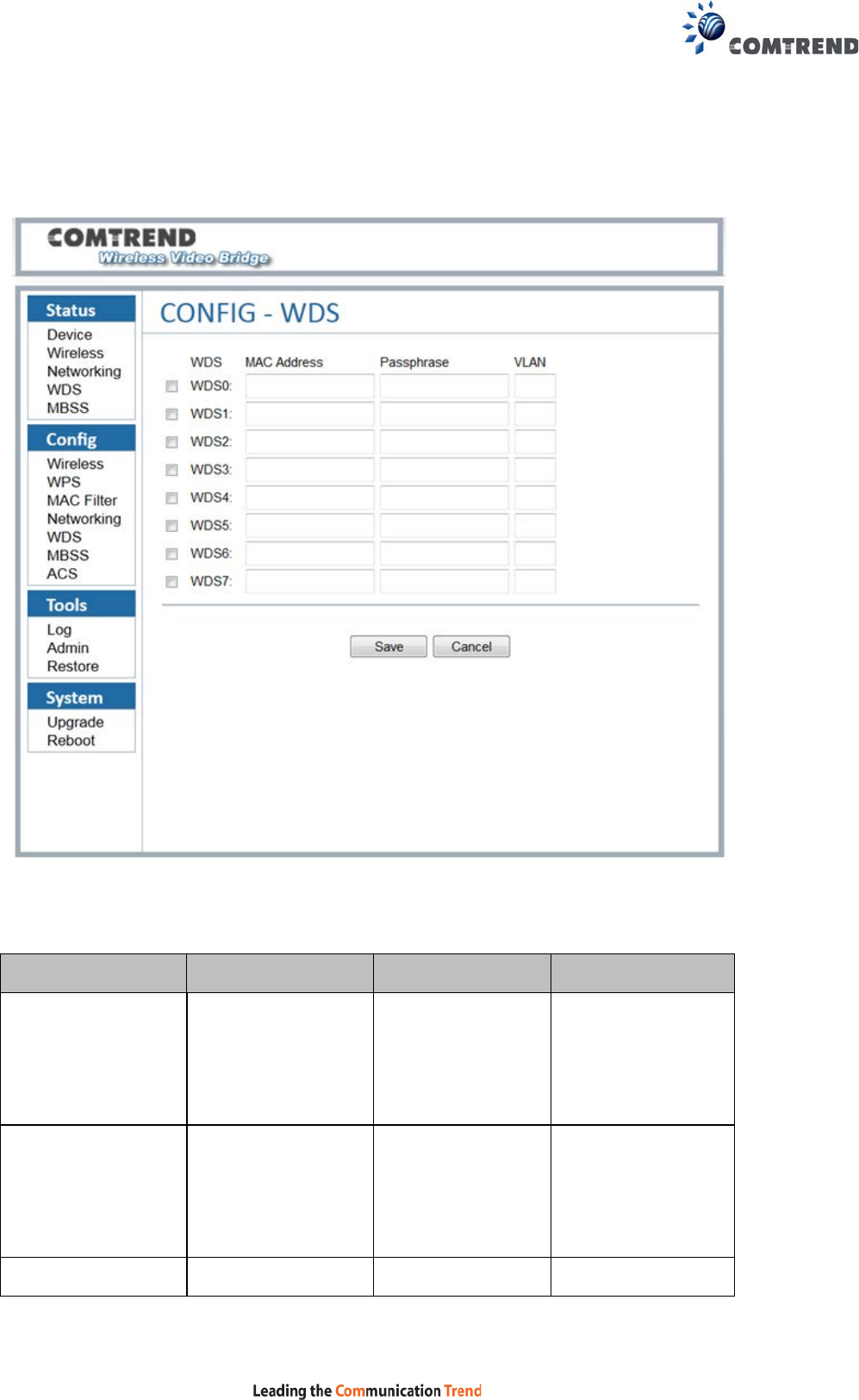
5.5 Config – WDS
This screen shows the configuration of the WDS links.
This option is not available if the device is configured as a STA.
Menu Item Description Options Detail
WDS checkbox To determine if the
WDS link is enabled
Checked
The WDS link will
be stored to a file
after clicking the
Save Button
Not Checked The WDS link will
be discarded after
clicking the Save
Button
MAC Address 48bit MAC address
The WDS peer MAC

40
address on the
opposite side
Passphrase
64 ASCII PSK
Wi-Fi devices can
see the SSID in
scan. Now the
passphrase string
is displayed as
"*******"
instead.
Empty
The WDS link does
not have security
VLAN Virtual Lan for
different interface
1-4096
41
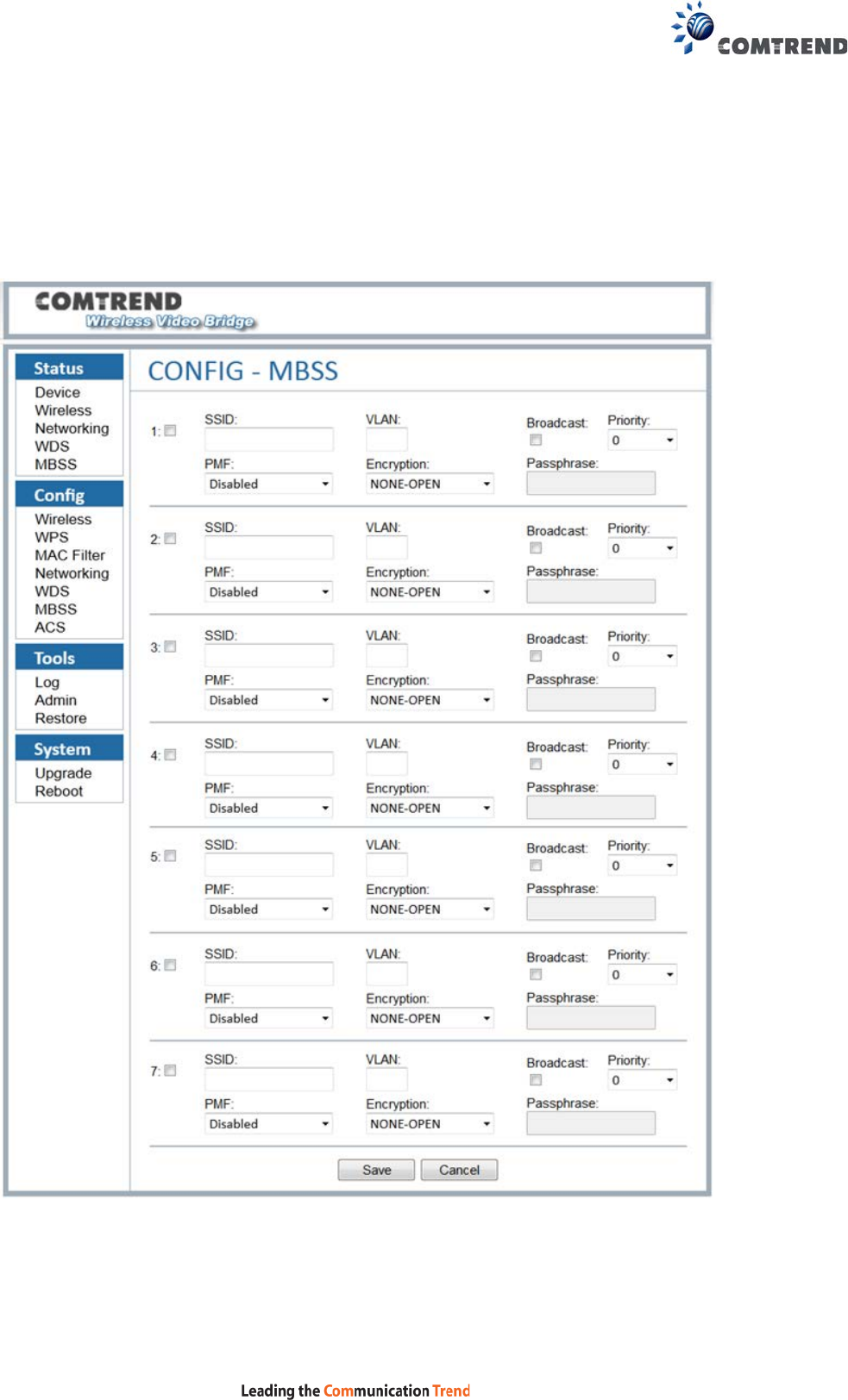
5.6 Config – MBSS
One can create multiple Basic Service Set Identifiers (BSSIDs) on a device initially
configured as an access point (AP). This capability is not available on a device
configured as a STA. The first step in creating an additional BSSID is to create the
wireless interface device for that BSSID.

42
Menu Item Description Options Detail
SSID SSID of the MBSS This will be the SSID
of the wireless
network.
VLAN Virtual Lan for different
interface
1-4096
Broadcast Enabled or disabled
SSID broadcast
Checked
SSID will be broadcast
Unchecked Wi-Fi devices can see
the SSID in scan
Priority The priority is used to
differentiate traffic
between different
SSIDs
0 is highest
priority.
3 is lowest
priority.
PMF Protected Management
Frames
Sets the 802.11w /
PMF capability. Applies
to AP
Encryption 802.11 compliant
encryption
NONE-OPEN
Disables encryption
(OPEN mode)
WPA2/AES
WPA2+WPA
(mixed mode)
Passphrase
The passphrase
applies to this MBSS
SSID
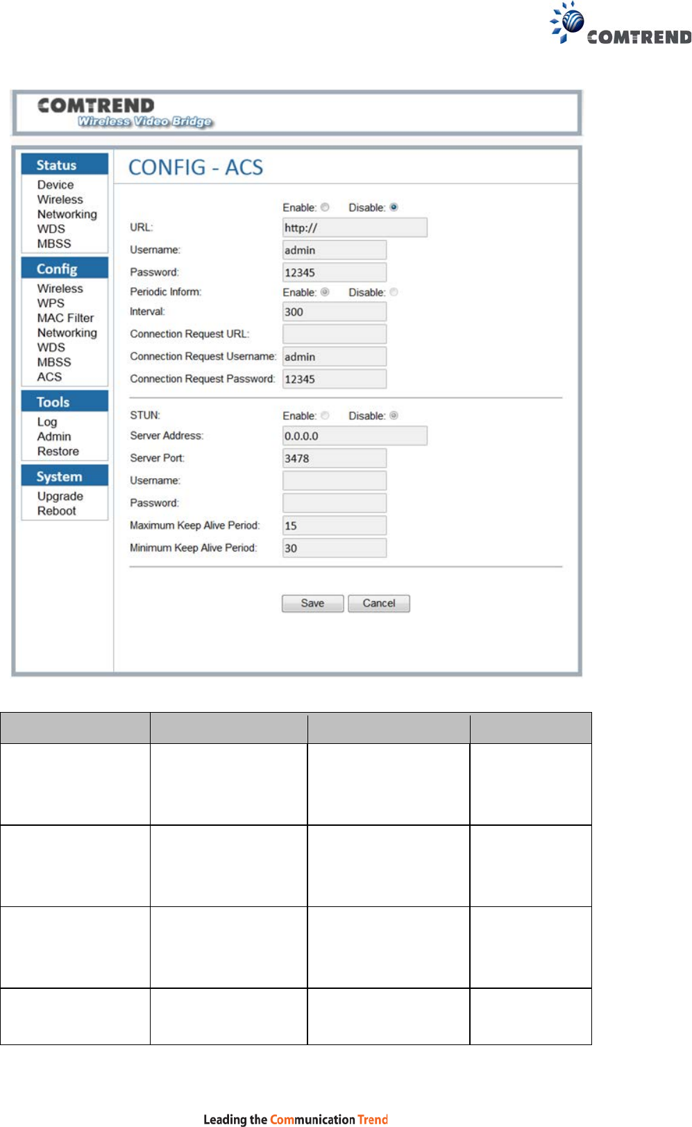
5.7 Config – ACS
WAN Management Protocol CWMP (TR-069) allows an Auto-Configuration Server
(ACS) to perform auto-configuration, provision, collection, and diagnostics to this
device. Select desired values and click SAVE to configure TR-069 options.
43
Menu Item Description Options Detail
Enable Enable TR-069
daemon connection
to ACS
Select to enable
Disable Disable TR-069
daemon connection
to ACS
Select to disable
URL IP address and port
the device uses to
connect to the ACS
Username Username used to
authenticate on ACS

44
Password Password used to
authenticate on ACS
Periodic Inform Activate /
Deactivate the info
message to ACS
server
Unit is
second(s)
Interval Periodic time
interval of sending
the info message
Connection
Request URL
The path for the
connection from the
ACS to the CPE. It is
recommended to
keep the default
setting.
Connection
Request
Username
Username used to
authenticate an ACS
making a
Connection Request
to the CPE
Connection
Request
Password
Password used to
authenticate an ACS
making a
Connection Request
to the CPE
STUN Activate the TR-111
function
Select to enable
Deactivate the
TR-111 function
Select to disable
Server Address IP address of device
used to connect to
the ACS which
support STUN
Server Port Port of device used
to connect to the

45
ACS which support
STUN
Username Username used to
authenticate on ACS
which support STUN
Password Password used to
authenticate on ACS
which support STUN
Maximum Keep
Alive Period
The maximum
connect duration to
the ACS server
Unit is
second(s)
Minimum Keep
Alive Period
The minimum
connect duration to
the ACS server
Unit is
second(s)
46
Chapter 6 Tools
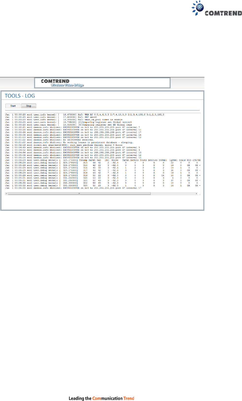
6.1 Tools – Log
This page has the ability to directly view the PHY statistics of the device.
Pressing the “Start” button will start a 10 second polling log. This data can be useful
to assist in debugging the system.
After selecting “Start”, the page will look similar to the image above. The logging will
stop after pressing the “Stop” button. If the IP address is changed or if the device is
shut off, this page will give an error message if logging was in progress. To recover
the session, please press the “Start” button again.
This interface takes data from an internal OS file, so intermittently; there may be
management messages that show up in this log.

47
Metric Description Comments
Tstamp This is the system time of
the measurement taken
from the internal system
clock
RxPkts
This represents the
number of packets that
were successfully received
over 1 second intervals.
Each line represents 1
second of time.
RxGain This is the higher receiver
gain value that was
recorded on successfully
received packets during
this measurement
interval. If no packets
were received, this may be
an invalid number.
The maximum value of
RxGain is 62
CRC This is the number of CRC
errors received over the 1
second measurement
interval
If (CRC/Rx Packets) >
10-20%, then the channel
condition or link quality is
poor. This is possibly due to
interference, another Wi-Fi
network or being too far for
the current configuration to
be reliable.
Noise This is the MAX receiver
noise floor as measured
over this 1 second interval
This value is an internal
noise calculation, not
external. In normal
operation it will vary
between 20 and 70.
TxPkts This is the number of
successfully transmitted
packets over the last 1
second interval.

48
Defers This number counts the
number of times an
attempted transmission
was deferred due to the
medium being busy.
This is helpful in
determining if an
environment is very busy.
Defers are common in busy
WiFi environments
Tout This is an indicator of Tx
packet timeout
Timeouts are not common.
The Packet could not find a
time slot to transmit.
Retries
This counts the number of
transmission retries that
have occurred over the
last one second.
This is primarily due to the
lack of acknowledgements
from the partner device.
On the transmit side, note
that the general packet flow
for error is as follows:
Defer
Retry
Timeout
ShPre This counts the number of
Short Preamble Detection
Errors
These are very common in
high throughput conditions
LgPre This counts the number of
Long Preamble Detection
errors
The wireless received a
signal which passed the
short preamble, but failed
the more complex long
preamble. These are less
common than short
preamble errors.
Rate This is a legacy
measurement for rate and
is not currently used
49
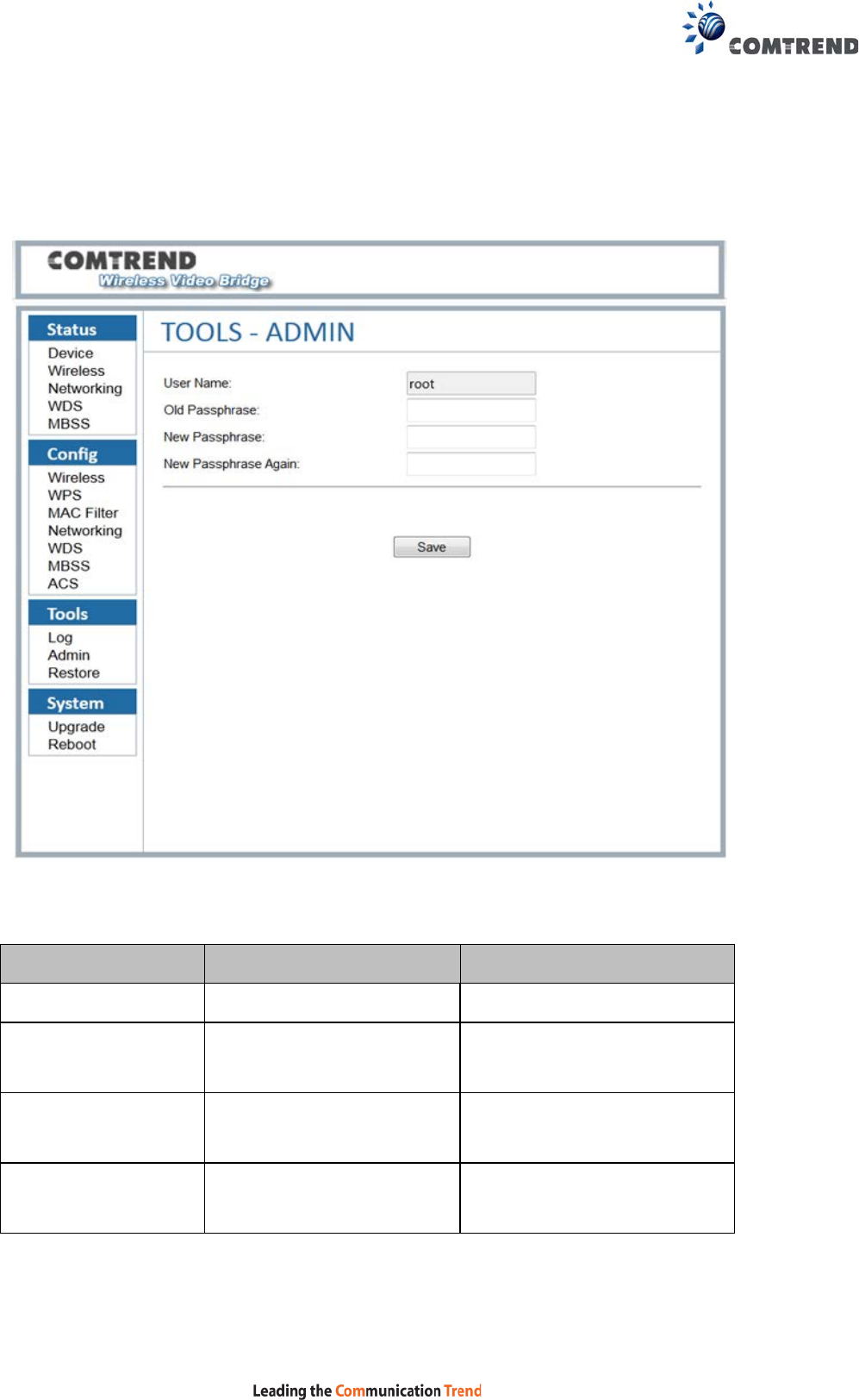
6.2 Tools – Admin
This page is for administration of the user passwords.
Menu Item Description Notes
User Name The user name for login Only for the login privilege
Old Passphrase Enter the original password
of the user name
New Passphrase Enter the new passphrase
New Passphrase
Again
Enter the new passphrase
again
It should be the same as the
“New Passphrase”
50
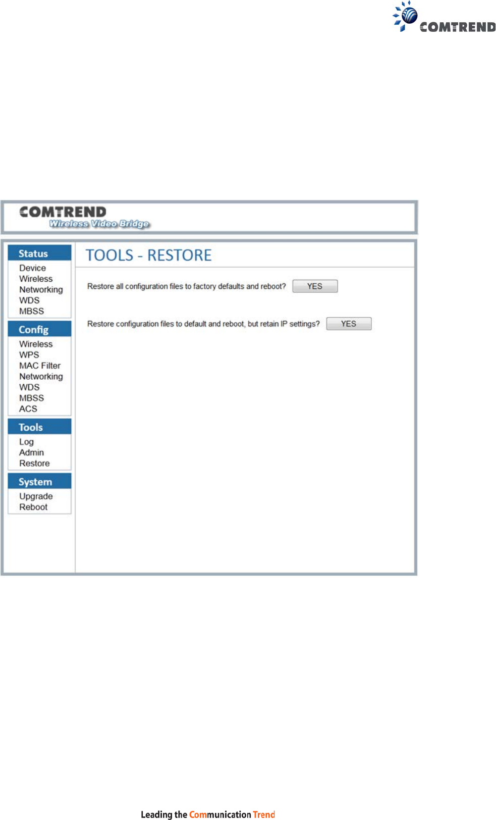
6.3 Tools – Restore
The Tools Restore page is for users to restore all the configurations of the device to
factory defaults. There is also the option to restore the configuration files and reboot
whilst retaining the IP settings.
The Restore function also restores the password of the login user.
51
Chapter 7 System
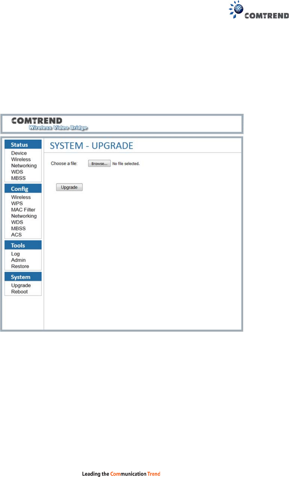
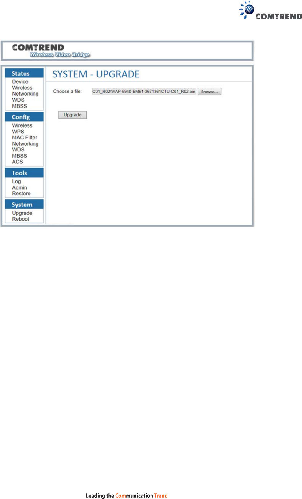
7.1 System – Upgrade
The System Upgrade page is for users to update the firmware on the device.
This page will upload a binary image file. Please use bin file to upgrade which is
named like “WAP-5940-EM51-3671361CTU-CXX_RXX.bin”.
When you select the file and click “Upgrade”, the “Upgrade” button will be disabled
and the page will display “Loading the image file......Please wait”, please wait for 2
minutes. Please be patient and do not power off the unit during this process.
Do not close the upgrade webpage.
52
When the firmware has been upgraded successfully, you will be automatically
directed to the reboot page.
53
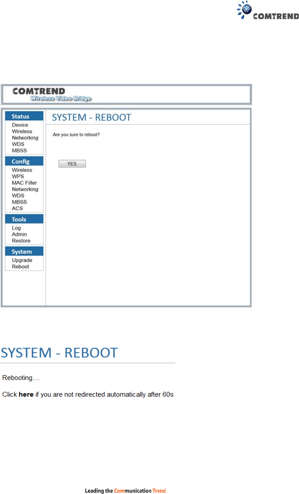
7.2 System – Reboot
The System Reboot page is for users to reboot the device.

54
Appendix A - Specifications
Hardware Interface
• AP/Station Switch x 1
• RJ-45 X 2 for Giga Ethernet port
• Reset Button X 1
• WPS button X 1
• 4x internal MIMO antenna
• Power switch X 1
• Power Jack X 1
Standard
• 802.11a/n/ac
• 802.11i (WEP, WPA/WPA2, RADIUS)
• 802.11d
• 802.11e (WMM, WMM-PS)
• 802.11w
• 802.11h
• 802.11k
• 802.11r
• 802.11s (Draft)
Rates are for 256 QAM
• 80MHz: 1.7Gbps
• 40MHz: 800Mbps
• 20MHz: 346.8Mbps
Environment Condition
Operating temperature .....................................0 ~ 40 degrees Celsius
NOTE: Specifications are subject to change without notice.
55
Appendix B - AP / Station
After you select AP mode thus the Ethernet port (ETH1) will be WAN port, another
Ethernet port (ETH2) is LAN side.

56
After you select station mode thus two Ethernet ports (ETH1, ETH2) are LAN side.

57
Warnings Guide
FCC Statements
This equipment has been tested and found to comply with the limits for a Class B digital device,
pursuant to Part 15 of the FCC Rules. These limits are designed to provide reasonable protection
against harmful interference in a residential installation. This equipment generates, uses and can
radiate radio frequency energy and, if not installed and used in accordance with the instructions, may
cause harmful interference to radio communications. However, there is no guarantee that interference
will not occur in a particular installation. If this equipment does cause harmful interference to radio or
television reception, which can be determined by turning the equipment off and on, the user is
encouraged to try to correct the interference by one or more of the following measures:
Reorient or relocate the receiving antenna.
Increase the separation between the equipment and receiver.
Connect the equipment into an outlet on a circuit different from that to which the receiver is
connected.
Consult the dealer or an experienced radio/TV technician for help.
FCC Caution: Any changes or modifications not expressly approved by the party responsible for
compliance could void the user's authority to operate this equipment.
This device complies with Part 15 of the FCC Rules. Operation is subject to the following two
conditions:
(1) This device may not cause harmful interference, and
(2) this device must accept any interference received, including interference that may cause undesired
operation.
IMPORTANT NOTE:
FCC Radiation Exposure Statement:
This equipment complies with FCC radiation exposure limits set forth for an uncontrolled environment.
This equipment should be installed and operated with minimum distance 20 cm between the radiator
& your body.
ISED Statements
This device complies with Industry Canada’s licence-exempt RSSs. Operation is subject to the following
two conditions:
1. This device may not cause interference, and
2. This device must accept any interference, including interference that may cause undesired
operation of the device.
Cet appareil est conforme à la norme RSSs Industrie Canada exempts de licence norme(s). Son
fonctionnement est soumis aux deux conditions suivantes:
1. Cet appareil ne peut pas provoquer d’interférences et
2. Cet appareil doit accepter toute interférence, y compris les interferences qui peuvent causer un
mauvais fonctionnement du dispositif.
IMPORTANT NOTE:
IC Radiation Exposure Statement:
This equipment complies with IC RSS-102 radiation exposure limits set forth for an uncontrolled
environment. This equipment should be installed and operated with minimum distance 20 cm
between the radiator & your body.
Cet équipement est conforme aux limites d'exposition aux rayonnements IC établies pour un
environnement non contrôlé. Cet équipement doit être installé et utilisé avec un minimum de 20 cm de
distance entre la source de rayonnement et votre corps.

58
Users should also be advised that high-power radars are allocated as primary users (i.e. priority users)
of the bands 5250-5350 MHz and 5650-5850 MHz and that these radars could cause interference
and/or damage to LE-LAN devices.
Other Statements
This device and its antenna(s) must not be co-located or operating in conjunction with any other
antenna or transmitter.
The device for operation in the band 5150–5250 MHz is only for indoor use to reduce the potential for
harmful interference to co-channel mobile satellite systems.
This device is restricted to indoor use.