Continental Automotive SV2007BSD 24 GHz Blind-Spot Radar Sensor User Manual Exhibit 8 User Manual
Continental Automotive GmbH 24 GHz Blind-Spot Radar Sensor Exhibit 8 User Manual
UserManual.wiki
>
Continental Automotive
>
SV2007BSD User Manual
08 user manual
Navigation menu
Upload a User Manual
Namespaces
Wiki Guide
HTML
PDF
Info
Views
User Manual
Discussion / Help
Navigation
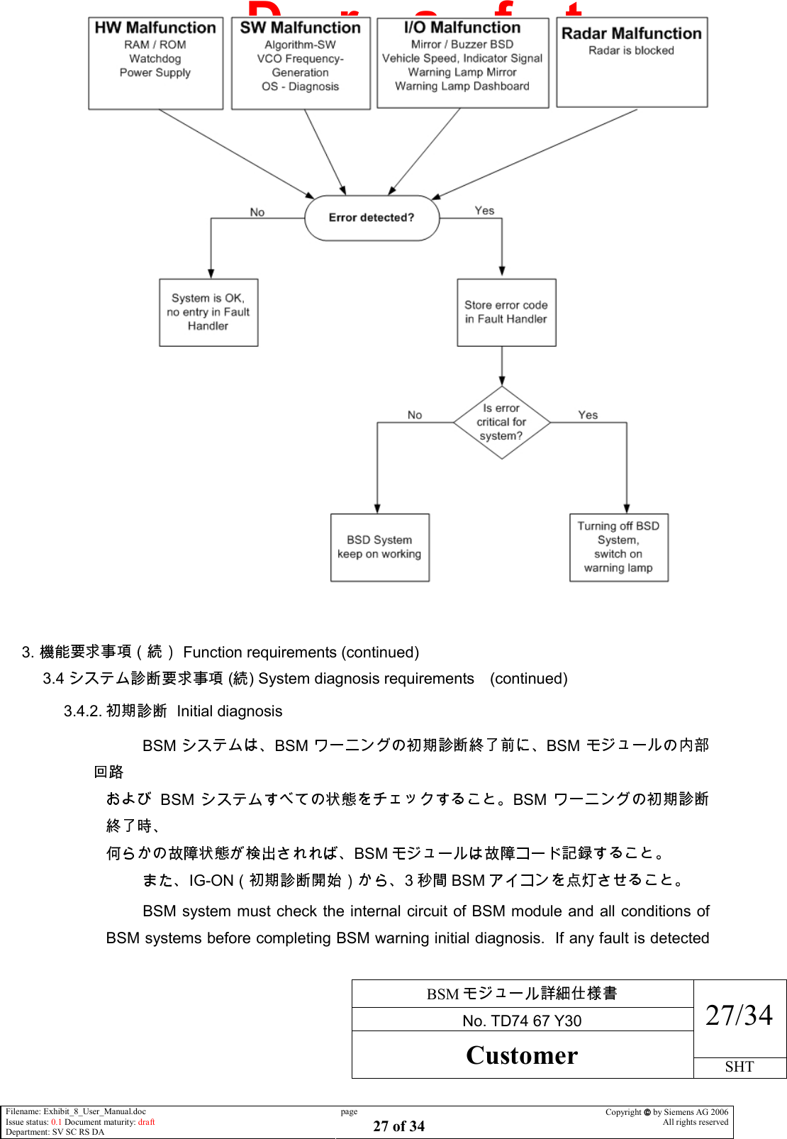
![BSM No. TD74 67 Y30 28/34 Customer SHT Filename: Exhibit_8_User_Manual.doc Issue status: 0.1 Document maturity: draft Department: SV SC RS DA page 28 of 34 Copyright by Siemens AG 2006 All rights reserved D r a f t when BSM warning initial diagnosis completed, BSM module must record the fault code. BSM icon shall be turned on 3 [sec] from IG-ON. (start of the initial check) 3.5. Fault code list (Trouble code and lighting condition) fault code and the detection condition BSD SUBSYSTEM SPECIFIC DIAGNOSTIC SPECIFICATION Fault code and the detection condition are according to ”BSD SUBSYSTEM SPECIFIC DIAGNOSTIC SPECIFICATION”. ( ) BSM system operation prohibition condition (software) BSM • uC RAM • uC ROM BSM system must stop the warning function to the driver when following hardware trouble is detected. • Micro processor volatile memory trouble. (uC RAM trouble) • Micro processor reading only memory trouble. (uC ROM trouble) 3.6. CAN CAN communication requirements 3.6.1. Requirements for information communication with other system BSM 1) BSM 2) BSM 3) BSM 4) BSM 5) BSM BSM 1 1](https://usermanual.wiki/Continental-Automotive/SV2007BSD/User-Guide-752661-Page-30.png)