Continental Automotive SV2007BSD 24 GHz Blind-Spot Radar Sensor User Manual Exhibit 8 User Manual
Continental Automotive GmbH 24 GHz Blind-Spot Radar Sensor Exhibit 8 User Manual
08 user manual
Filename: Exhibit_8_User_Manual.doc
Issue status: 0.1 Document maturity: draft
Department: SV SC RS DA
page
1 of 34
Copyright
by Siemens AG 2006
All rights reserved
Exhibit 8 – User Manual
SV SC RS DA
Draft User Manual for
24 GHz Blind-Spot Radar Sensor
AUTHORS
Name Organisation Section
Dr. Martin Kunert SV SC RS DA External Affairs
Remark:
This end-customer user manual is a draft version still under construction. It is written in Japanese language
because the end-customer (car manufacturer) is headquartered in Japan.
The frequency approval relevant information can be found on page 7 and 8 (with English translation).
BSM
No. TD74 67 Y30
2/34
Customer
SHT
Filename: Exhibit_8_User_Manual.doc
Issue status: 0.1 Document maturity: draft
Department: SV SC RS DA
page
2 of 34
Copyright
by Siemens AG 2006
All rights reserved
D
r
a
f
t
‘06.04.11
APPROVED
TD74 67 Y30
CHECKED B/S/M
MODULE- B/S/M
DESIGNED
5AEZC6-001
RESTRICTED
RESTRICTEDRESTRICTED
RESTRICTED
DD
DDDD
DD
B/S/M モジュール詳細仕様書
モジュール詳細仕様書モジュール詳細仕様書
モジュール詳細仕様書
B/S/M Module Detailed Specifications
NEW
Version
Ver. 1.0
1
‘06.08.30
Ver. 2.0
2 Spec change for J50c8
’06.10.18
Ver.3.0
BSM
No. TD74 67 Y30
3/34
Customer
SHT
Filename: Exhibit_8_User_Manual.doc
Issue status: 0.1 Document maturity: draft
Department: SV SC RS DA
page
3 of 34
Copyright
by Siemens AG 2006
All rights reserved
D
r
a
f
t
DWG. DATE QUALITY TYPE
’06.04.11 AR,B WORD
( )
(
BSM
No. TD74 67 Y30
2/34
Customer
SHT
Filename: Exhibit_8_User_Manual.doc
Issue status: 0.1 Document maturity: draft
Department: SV SC RS DA
page
2 of 34
Copyright
by Siemens AG 2006
All rights reserved
D
r
a
f
t
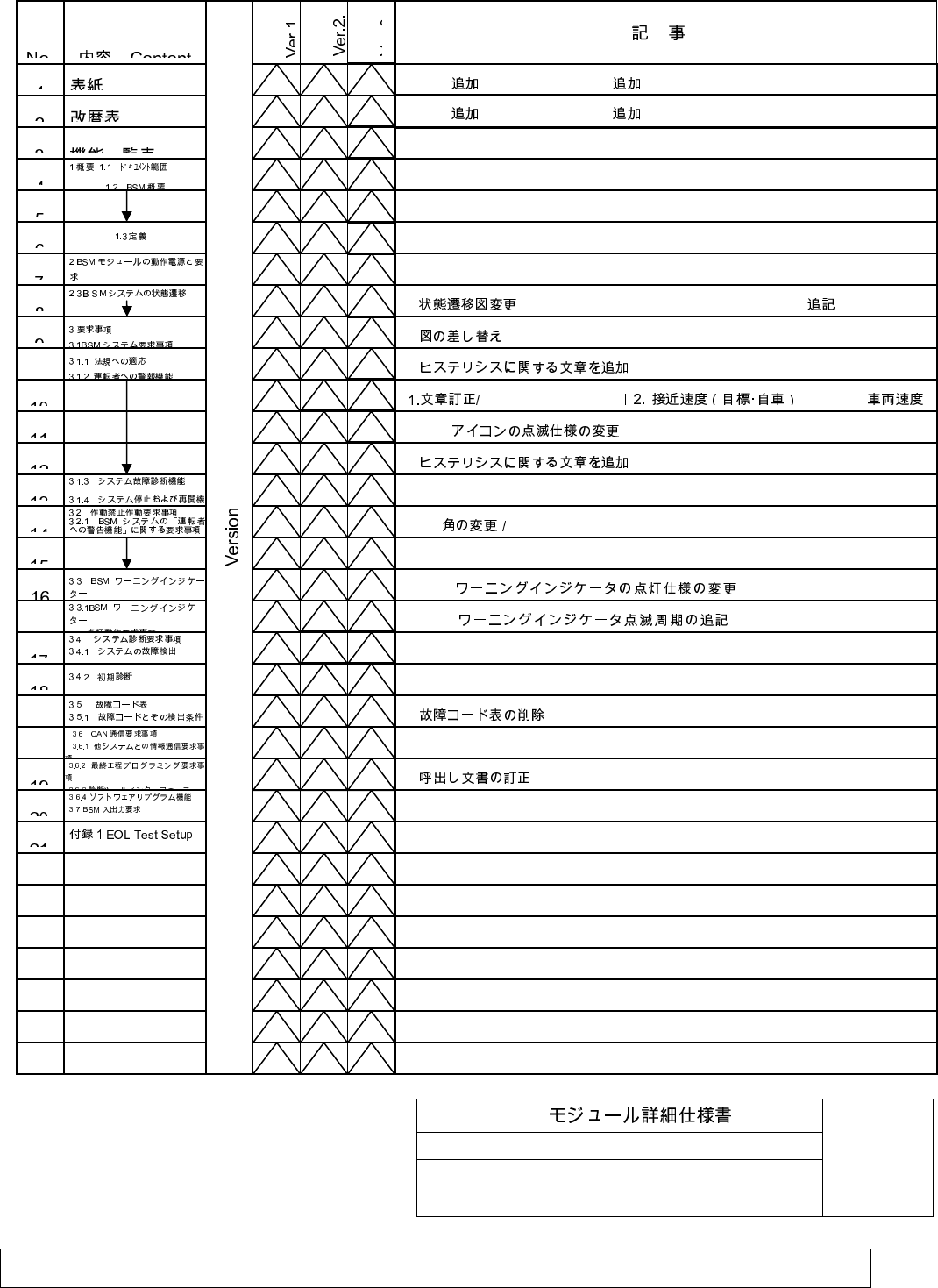
Revision History:
1
1
0
0
0
0
0
1
0
1
1
1
1
0
0
0
1
0
0
0
1
0
1
0
0
1.Ver.2
/ Add Ver.2 2. Ver.3
/ Add Ver.3
1.
/ Change state flow 2. LH&RH BSM failure status
2.
/Change the figure.
1.
/Add sentence for the hysterisis
Correct the senteces
/ BSM ON
1.BSM
/ Blink specification for the BSM icon is changed.
1.
/Add sentence for the hysterisis
2.Tilt
Change tilt angle
1.BSM
/
Spec. for the BSM lamp is
2.BSM
/ Frequency for BSM lamp is
1.
/
Delete DTC table
1.
/ Called document is corrected.
1.Ver.2
/ Add Ver.2 2. Ver.3
/ Add Ver.3
BSM
No. TD74 67 Y30
3/34
Customer
SHT
Filename: Exhibit_8_User_Manual.doc
Issue status: 0.1 Document maturity: draft
Department: SV SC RS DA
page
3 of 34
Copyright
by Siemens AG 2006
All rights reserved
D
r
a
f
t
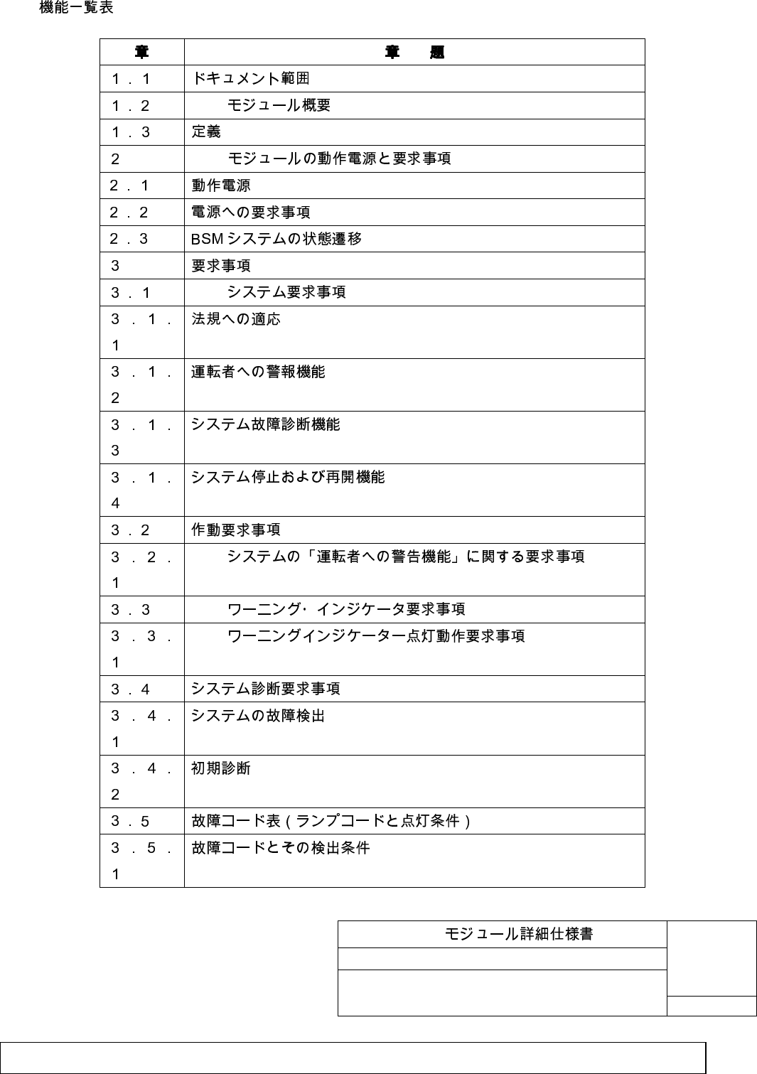
Contents list
BSM
BSM
BSM
BSM
BSM
BSM
BSM
No. TD74 67 Y30
4/34
Customer
SHT
Filename: Exhibit_8_User_Manual.doc
Issue status: 0.1 Document maturity: draft
Department: SV SC RS DA
page
4 of 34
Copyright
by Siemens AG 2006
All rights reserved
D
r
a
f
t
CAN
BSM
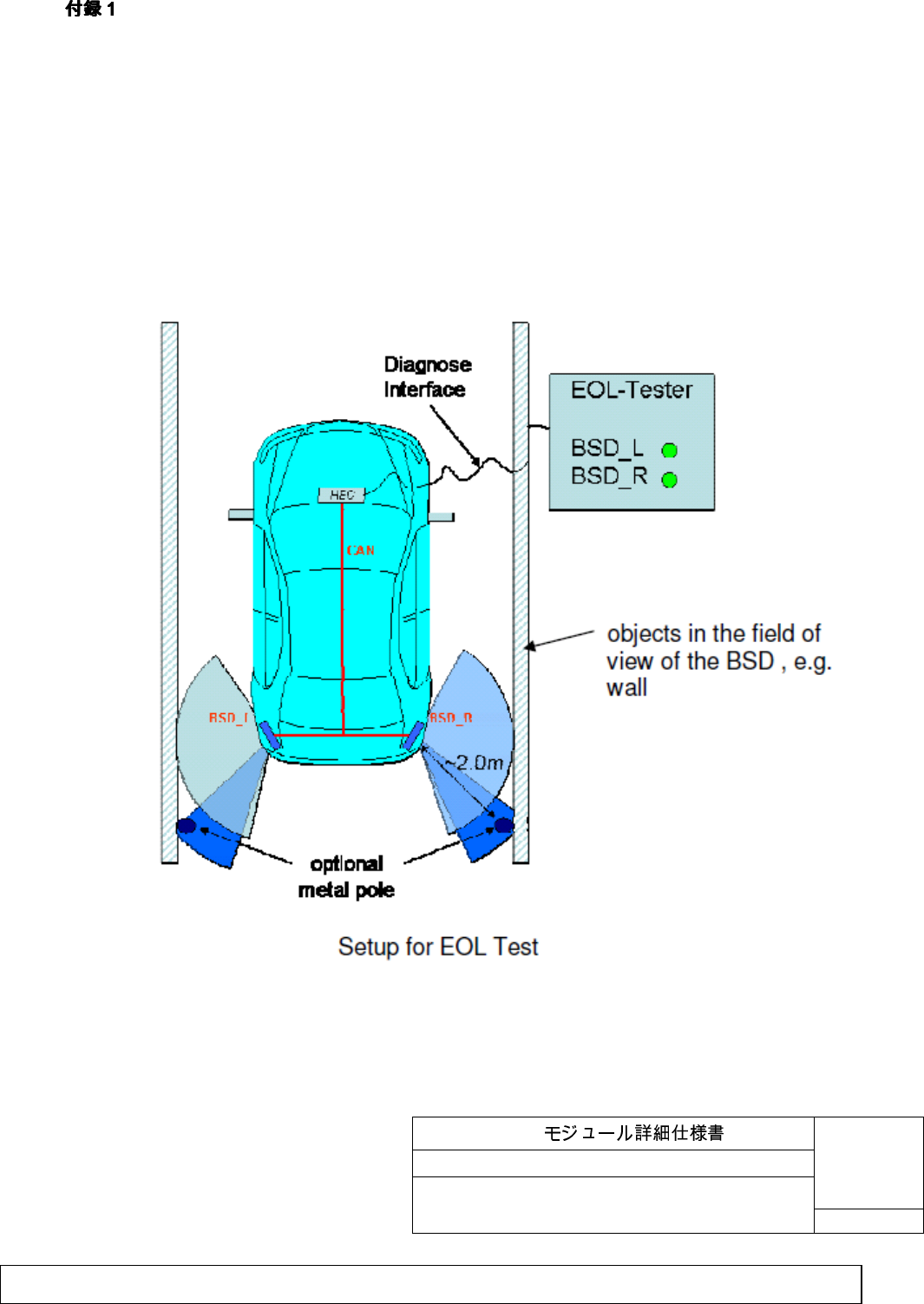
1 EOL Test Setup
BSM
No. TD74 67 Y30
5/34
Customer
SHT
Filename: Exhibit_8_User_Manual.doc
Issue status: 0.1 Document maturity: draft
Department: SV SC RS DA
page
5 of 34
Copyright
by Siemens AG 2006
All rights reserved
D
r
a
f
t
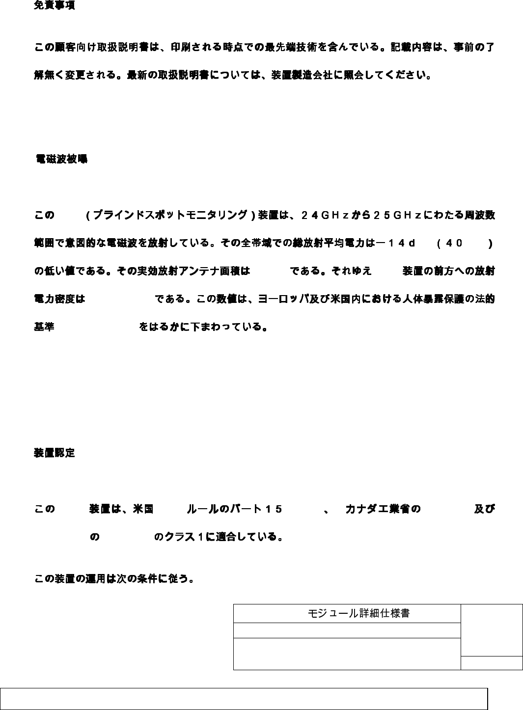
Disclaimer
This user manual contains the technical state of the art when passing for press. Subject to change
without prior notice. Please refer to the equipment supplier for updated manuals.
Radiation Hazard
BSM
Bm µW
72 cm
2
BSM
0.55 µW/cm
2
1 mW/ cm
2
(MPE)
This BSM (blind spot monitoring) device emits intentional electromagnetic radiation in the 24 GHz to
25 GHz frequency range. The total radiated average power over the entire bandwidth is below – 14
dBm (40 µW). The active emitting antenna surface is 72 cm
2
; therefore the radiated power density in
front of the BSM device is 0.55 µW/cm
2
. This value is far below the legal human exposure protection
limit of 1 mW/ cm
2
(MPE) in Europe and US.
Equipment Authorization
BSM FCC (15.252) RSS-210
ETSI/CEPT EN302288
BSM
No. TD74 67 Y30
6/34
Customer
SHT
Filename: Exhibit_8_User_Manual.doc
Issue status: 0.1 Document maturity: draft
Department: SV SC RS DA
page
6 of 34
Copyright
by Siemens AG 2006
All rights reserved
D
r
a
f
t
FCC ID: KR5SV2007BSD
CAN: XXX123456789
This BSM devices complies with part 15 of the FCC rules (15.252), with RSS-210 of Industry Canada
and with EN 302288 of ETSI/CEPT on a Class1 basis.
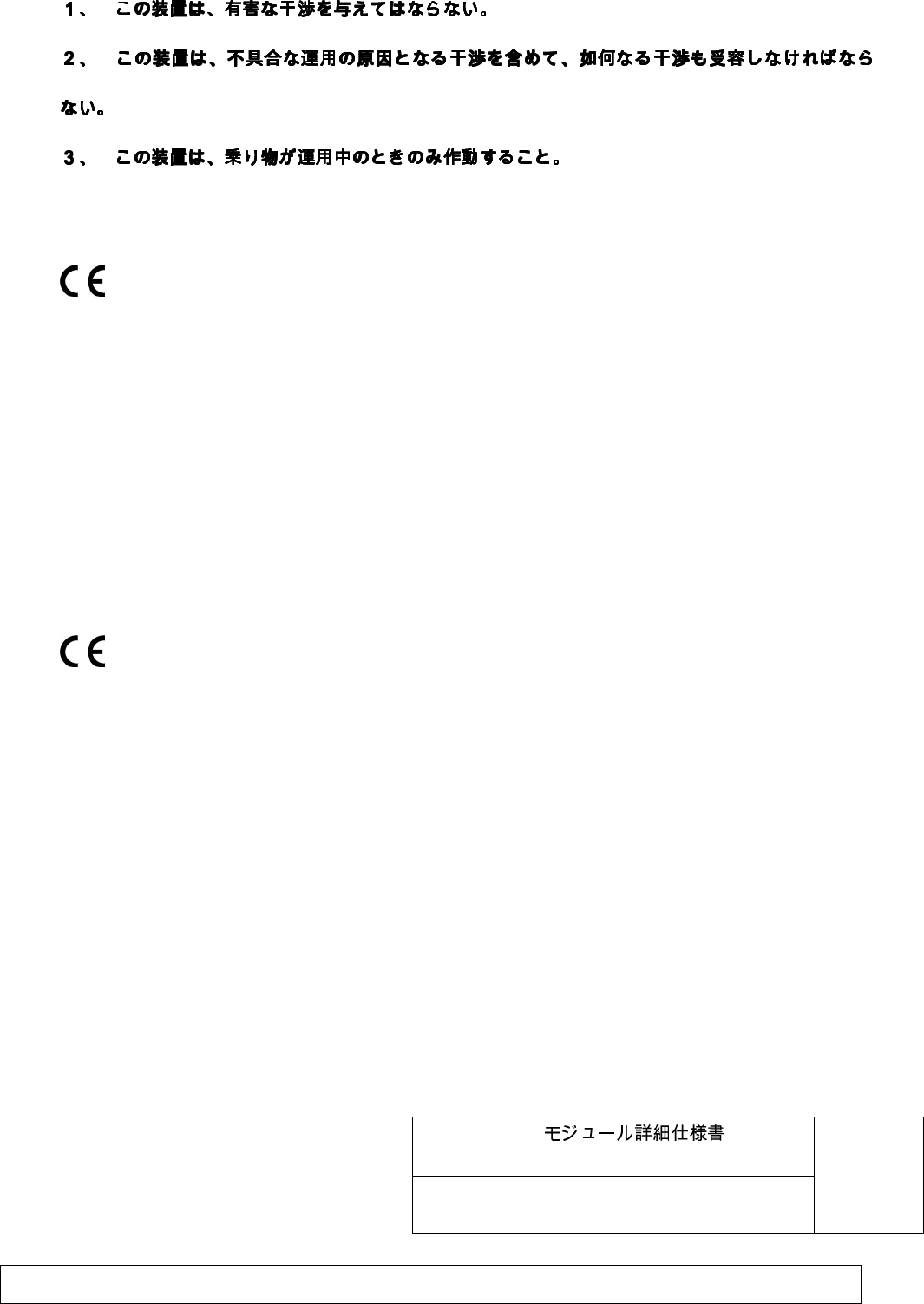
Operation is subject to the following conditions:
1. This device may not cause harmful interference, and
2. This device must accept any interference received, including interference that may cause
undesired operation.
3. This device may only work when the vehicle is in operation.
FCC ID: KR5SV2007BSD
CAN: XXX123456789
BSM
No. TD74 67 Y30
7/34
Customer
SHT
Filename: Exhibit_8_User_Manual.doc
Issue status: 0.1 Document maturity: draft
Department: SV SC RS DA
page
7 of 34
Copyright
by Siemens AG 2006
All rights reserved
D
r
a
f
t
1. (General)
1.1. (Scope of this document
BSM
BSM
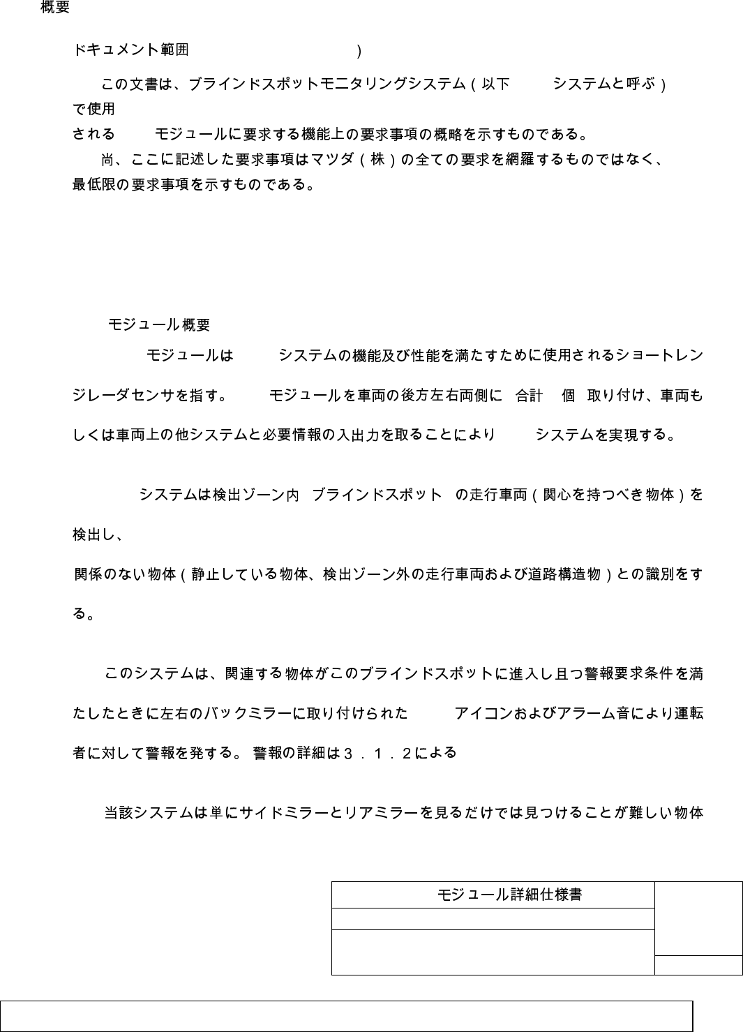
This specification describes the hardware and key function requirements for mass
production parts of a BSM module for Customer BSM system.
Note that the requirements described herein do not cover all of Customer’s requirements but
covers only the minimum requirements.
1.2. BSM (Outline of the BSM Module)
BSM BSM
BSM ( 2 )
BSM
BSM ( )
BSM
( )
BSM
No. TD74 67 Y30
8/34
Customer
SHT
Filename: Exhibit_8_User_Manual.doc
Issue status: 0.1 Document maturity: draft
Department: SV SC RS DA
page
8 of 34
Copyright
by Siemens AG 2006
All rights reserved
D
r
a
f
t
BSM BSM
HEC BSM
BSM IG1 OFF→ON BSM
BSM BSM
BSM
1. ( ) (General) (continued)
1.2 BSM ( ) (Outline of the BSM Module) (continued)
BSM module refers to short range radar sensor used to fulfill the function and performance
of BSM system. BSM system will be implemented by installing BSM module on both right and left
hand side behind the rear bumper of the subject vehicle (2pieces in total). The BSM modules
communicate via CAN to obtain input and output of necessary data with vehicle itself and other
systems on the vehicle.
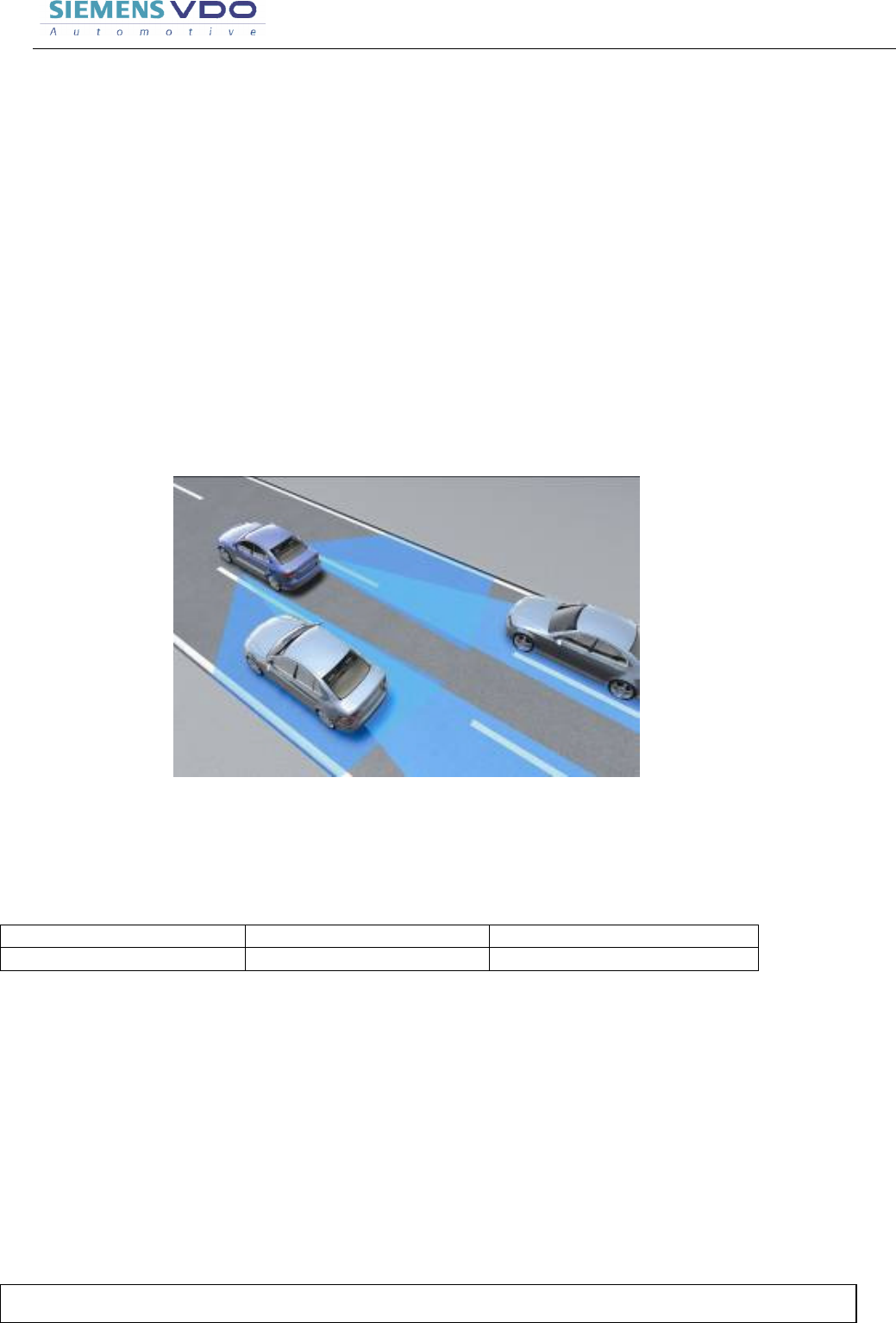
BSM system detects moving vehicles (objects of interest) within the detection zone (blind
spot) to identify the non relevant objects. (stationary objects, moving vehicles outside of detection
zone and road infrastructure)
This system warns the driver by illuminating of an BSM icon installed on right and left rear
view mirror (first level warning) and alarm sound (2
nd
level warning coupled with turn indicator
signal) when an object of interest enters the warning zone and the warning requirement condition
is fulfilled. (Details of the warning is referred in 3.1.2)

BSM
No. TD74 67 Y30
9/34
Customer
SHT
Filename: Exhibit_8_User_Manual.doc
Issue status: 0.1 Document maturity: draft
Department: SV SC RS DA
page
9 of 34
Copyright
by Siemens AG 2006
All rights reserved
D
r
a
f
t
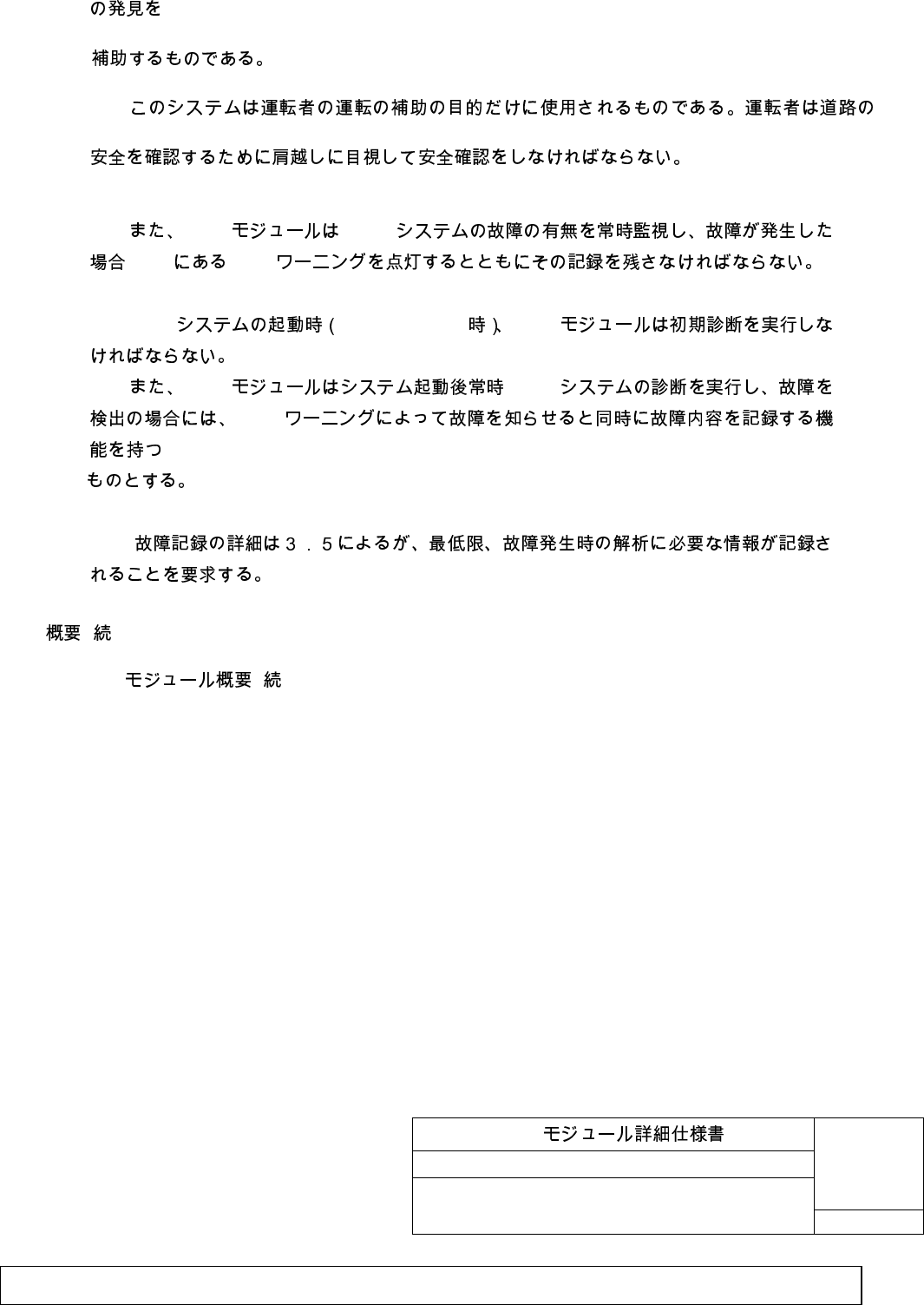
This system supports to recognize the objects hardly found just by viewing side and rear
view mirrors.
This is used exclusively for driving support for the driver. The driver must check with eyes
over his/her shoulder to confirm the safety. The BSM system is not intended to substitute the rear
view mirror of the subject vehicle. The system is for supplemental use only. The driver is still
100% responsible for his actions.
Also BSM module is checking the system faults on BSM system all the time, and when any
system fault is detected, it must turn on the BSM warning in HEC and must record the Fault code.
BSM module must perform initial diagnosis when BSM system is started up. (IG1
when OFF => ON)
Additionally, BSM module implements BSM system diagnosis every time system starts
up, and has a function to warn the trouble by BSM warning and record the trouble details
when detecting a trouble.
The detail of trouble record is according 3.5, however it is required at least to record
the necessary data for analyzing when trouble occurs.
1. General continued.
1.3. (Definitions)
1) BSM (BSM system)
Blind Spot Monitoring BSM
Abbreviation of Blind Spot Monitoring System,
This system covers the blind spot of the driver with short-distance radar sensor and warn the
driver when the warning condition is fulfilled.
2) BSM (BSM module)
BSM 2
BSM
No. TD74 67 Y30
10/34
Customer
SHT
Filename: Exhibit_8_User_Manual.doc
Issue status: 0.1 Document maturity: draft
Department: SV SC RS DA
page
10 of 34
Copyright
by Siemens AG 2006
All rights reserved
D
r
a
f
t
Sensor module used with BSM system. 2 pieces are used on the left and right for 1 system.
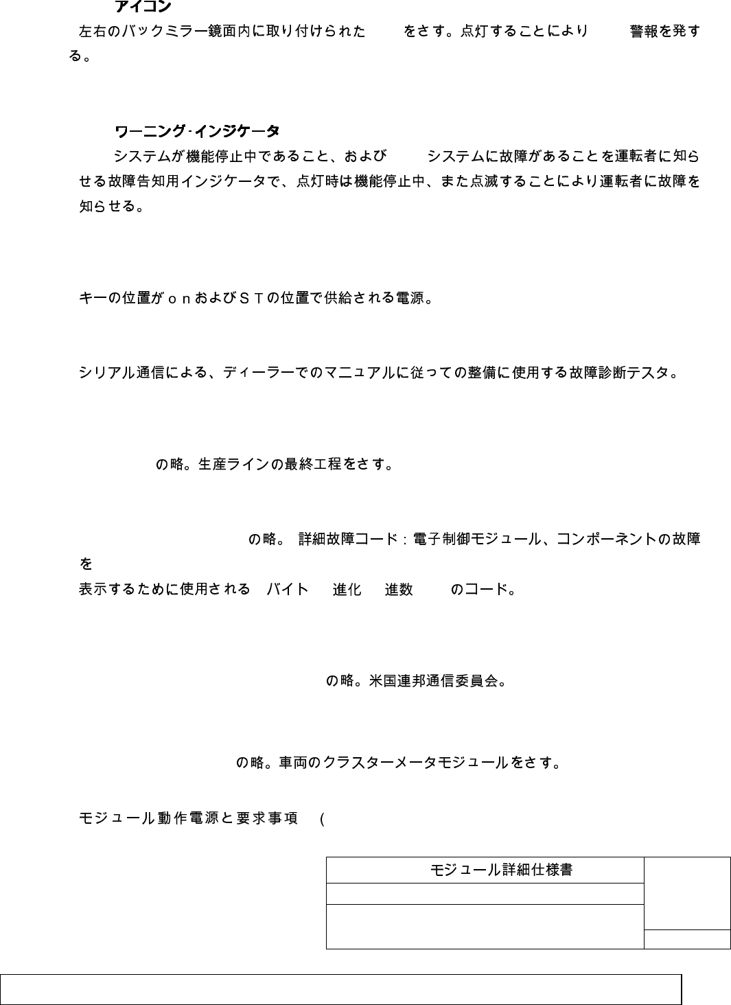
3) BSM (BSM icon)
LED BSM
Refers to LED installed in left and right rear view mirror surface. Sends out BSM warning by
lighting.
4) BSM (BSM warning indicator)
BSM BSM
Diagnostic indicator to warn the driver that BSM system is not functioning and having a problem.
Warn the driver that the system is not functioning by lighting, and trouble by blinking.
5) IG1 ON
Power supplied when the key is positioned at ON and ST.
6) MMDS (Customer Modular Diagnostic System) Tester
Diagnosis tester used for maintenance following the manual at dealers by serial
communications.
7) EOL
End of Line
Abbreviation of End of Line. Referring the final process of production line.
8) DTC
Diagnostic Trouble Code
3 10 16 /BCD
Abbreviation of Diagnostic Trouble Code of 3 byte, 10 evolution, HEX-decimal /BCD used for
indicating detailed trouble code: electronic control module and component.
9) FCC
Federal Communications Commission
Abbreviation of Federal Communications Commission.
10) HEC
Hybrid Electrical Cluster
Abbreviation of Hybrid Electrical Cluster.
2. BSM The operation voltage and the requirements for BSM
BSM
No. TD74 67 Y30
11/34
Customer
SHT
Filename: Exhibit_8_User_Manual.doc
Issue status: 0.1 Document maturity: draft
Department: SV SC RS DA
page
11 of 34
Copyright
by Siemens AG 2006
All rights reserved
D
r
a
f
t
Module)
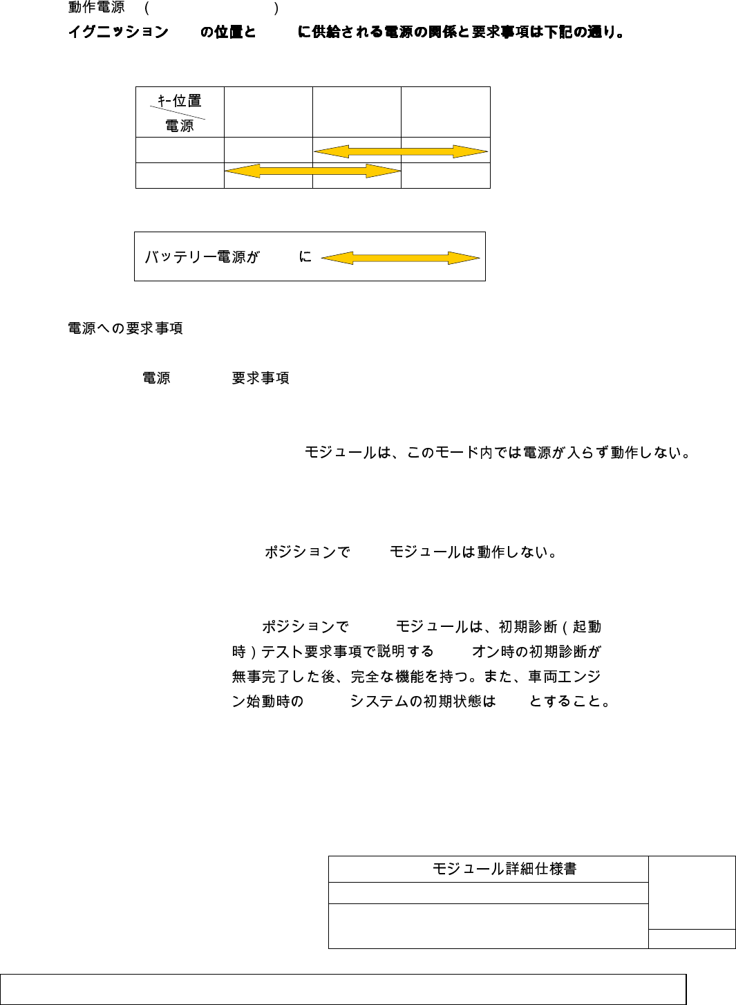
2.1. Operation voltage
SW BSM
2.2. (The requirements for the voltage)
Power Requirement
ACC - BSM
(Due to no power supply to the Modules, BSM Module is not working in
this mode.)
OFF - OFF BSM
BSM Module is not working in “OFF” position.
IG1 - IG1 BSM
IG1
BSM “ON”
At IG1 position, BSM module will have complete function after
finishing the initial diagnosis at IG1 ON explained in initial diagnosis
(when starting up) test requirements with no problem. In addition, BSM
system initial condition when starting the vehicle engine must be "ON".
ACC ON START
IG1
ACC
BSM
BSM
No. TD74 67 Y30
12/34
Customer
SHT
Filename: Exhibit_8_User_Manual.doc
Issue status: 0.1 Document maturity: draft
Department: SV SC RS DA
page
12 of 34
Copyright
by Siemens AG 2006
All rights reserved
D
r
a
f
t
2. BSM ( ) The operation voltage and the requirements for BSM
Module) (continued)
2.2 (The requirements for the voltage) continued
BSM
In the cranking process of the vehicle, BSM Modules should not record the
fault records, because of the voltage change due to the cranking.
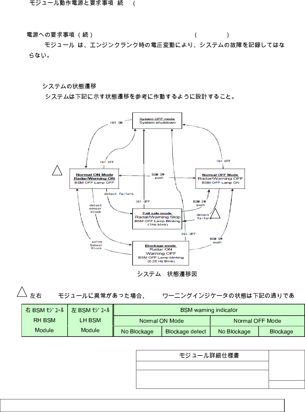
2.3. BSM
BSM
BSM system shall be working like as following state flow.
BSM (Reference)
BSM system state flow (Reference)
BSM BSM
1
2
2
BSM
No. TD74 67 Y30
13/34
Customer
SHT
Filename: Exhibit_8_User_Manual.doc
Issue status: 0.1 Document maturity: draft
Department: SV SC RS DA
page
13 of 34
Copyright
by Siemens AG 2006
All rights reserved
D
r
a
f
t
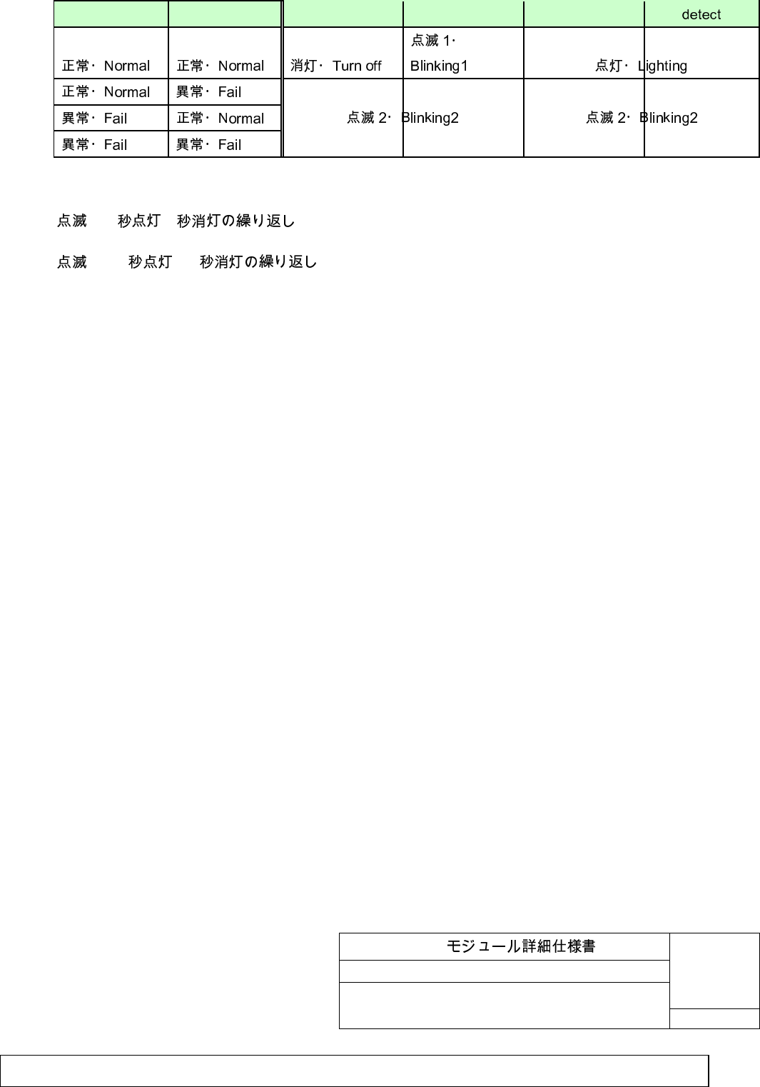
3.
1: 2 /2 / Blinking1: 2sec ON/2sec OFF repeat
2: 0.5 /0.5 / Blinking2: 0.5sec ON/0.5sec OFF repeat
BSM
No. TD74 67 Y30
14/34
Customer
SHT
Filename: Exhibit_8_User_Manual.doc
Issue status: 0.1 Document maturity: draft
Department: SV SC RS DA
page
14 of 34
Copyright
by Siemens AG 2006
All rights reserved
D
r
a
f
t
(Requirement for the function of the BSM Modules)
3.1. BSM (BSM system requirements)
3.1.1. (Application for regulations)
BSM B/S/D SHT3/6
BSM system requires applying for the regulations, which are written in
“B/S/D module drawing SHT 3/6”.
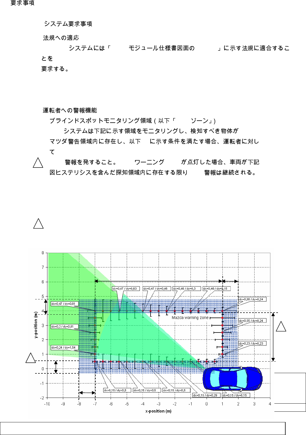
3.1.2. (Warning function to drivers)
1) BSM
BSM
2)
BSM BSM LED
BSM
1) Blind spot monitoring zone (“BSM zone” hereby after)
BSM system must monitor the zone indicated below, and alarm the driver with
BSM warning when a detected object is inside the Customer warning zone
and the warning condition (stated 2) below) are fulfilled. Once the warning
was enabled, the warning might stay for vehicle being in the detection zone
including the hysteresis zone indicated in the figure below.
1m
1m
1m
3.8
m
7
m
1
2
2
1
BSM
No. TD74 67 Y30
15/34
Customer
SHT
Filename: Exhibit_8_User_Manual.doc
Issue status: 0.1 Document maturity: draft
Department: SV SC RS DA
page
15 of 34
Copyright
by Siemens AG 2006
All rights reserved
D
r
a
f
t
3. ( ) (Requirement for the function of the BSM Modules) (continued)
3.1 BSM ( ) (BSM system requirements) (continued)
3.1.2 ( ) Warning function (continued)
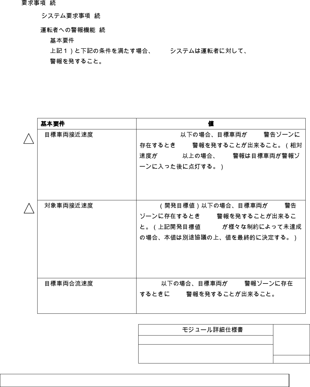
2)
BSM BSM
2) Basic requirements
BSM system must alarm the driver with BSM warning when above 1) and
following conditions are fulfilled.
Basic requirements Value
-
Target vehicle approaching
speed
(Target overtakes subject)
12 m/s(43kph) BSM
BSM
12m/s BSD
In case of less than 12m/s(43kph), system can make
warning during target vehicle is in BSM warning zone.
(For relative speed above 12m/s, the target is already inside
the warning zone before the warning occurs.)
-
Object vehicle approaching
speed
(Subject overtakes target)
10mph BSM
BSM
10mph
In case of less than 10mph (development target), system
can make warning during target vehicle is in BSM warning
zone. (If the “development target 10mph” is not achieved
caused by any reasons, this final value is defined again in
according to discussion.)
-
Target vehicle merging speed
(Merge – in scenario)
2.4 m/s BSM
BSM
In case of less than 2.4m/s, system can make warning
during target vehicle is in BSM warning zone.
1m
2
2
BSM
No. TD74 67 Y30
16/34
Customer
SHT
Filename: Exhibit_8_User_Manual.doc
Issue status: 0.1 Document maturity: draft
Department: SV SC RS DA
page
16 of 34
Copyright
by Siemens AG 2006
All rights reserved
D
r
a
f
t
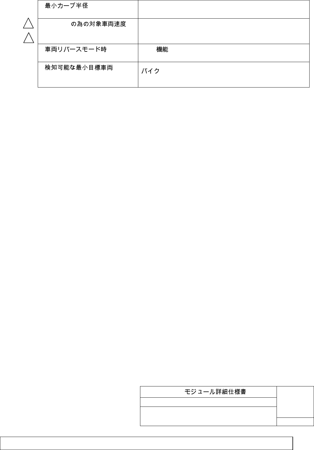
-
Minimum curve diameter > 125m
- BSM ON
Object vehicle speed for BSM
ON(system activation speed)
> 20mph
-
At vehicle reverse mode
BSM off
BSM function off
-
Minimum detectable target
vehicle
(ISO/ TC204/WG14/N40.28)
Motorbike
1
2
BSM
No. TD74 67 Y30
17/34
Customer
SHT
Filename: Exhibit_8_User_Manual.doc
Issue status: 0.1 Document maturity: draft
Department: SV SC RS DA
page
17 of 34
Copyright
by Siemens AG 2006
All rights reserved
D
r
a
f
t
3. ( ) (Requirement for the function of the BSM Modules) (continued)
3.1 BSM ( ) (BSM system requirements) (continued)
3.1.2 ( ) Warning function (continued)
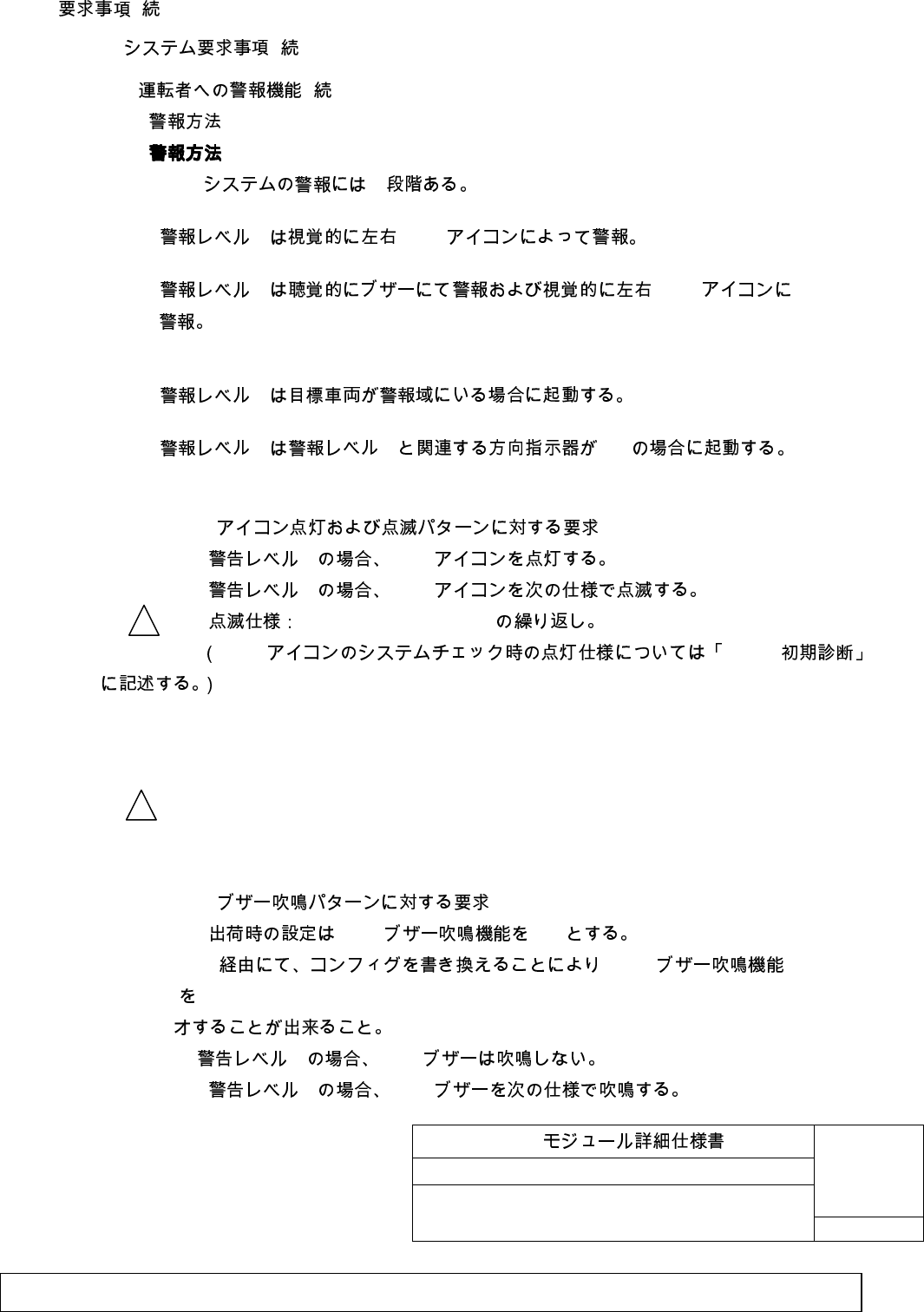
3) Warning method
a) BSM
1 BSM
2 BSM
0.25s ON/ 0.25s OFF
BSM 3.4.2
a) Requirement for blinking pattern of BSM icon
In case of warning level 1, BSM icon turns on.
In case of warning level 2, BSM icon blinks as follows.
Blink Spec: Cyclic 0.25s ON/ 0.25s OFF
(BSM icon indication specification of the system initial diagnosis is written in “3.4.2
Initial diagnosis”.)
b) BSM
BSM ON
CAN BSM
1 BSM
2 BSM
Warning method
- BSM 2
There are 2 levels of BSM system warning.
- 1 BSM
Warning level1 warns visually by left and right BSM Icon.
- 2 BSM
Warning level2 provides audible warning by buzzer and visual warning by left
and right BSM Icon.
- 1
Warning level1 starts up when target vehicle is in warning zone.
- 2 1 On
Warning level2 starts when turn signal related to warning level1 is On.
1
1
BSM
No. TD74 67 Y30
18/34
Customer
SHT
Filename: Exhibit_8_User_Manual.doc
Issue status: 0.1 Document maturity: draft
Department: SV SC RS DA
page
18 of 34
Copyright
by Siemens AG 2006
All rights reserved
D
r
a
f
t
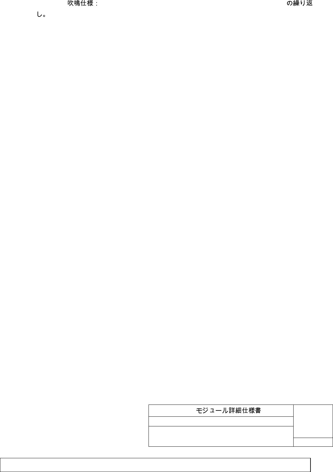
0.05s ON/0.05sOFF,0.05sON/0.05s OFF,0.05s ON/0.750s OFF
b) Requirement for sound pattern of BSM buzzer
BSM buzzer shall be ON in default setting at the end of production.
BSM buzzer can be turned off by rewriting the system configuration via CAN.
In case of warning level 1, BSM buzzer sounds.
In case of warning level 2, BSM buzzer sounds as follows.
Buzzer Spec: Cyclic 0.05s ON/0.05sOFF,0.05sON/0.05s OFF, 0.05s ON/0.750s OFF
BSM
No. TD74 67 Y30
19/34
Customer
SHT
Filename: Exhibit_8_User_Manual.doc
Issue status: 0.1 Document maturity: draft
Department: SV SC RS DA
page
19 of 34
Copyright
by Siemens AG 2006
All rights reserved
D
r
a
f
t
3. ( ) (Requirement for the function of the BSM Modules) (continued)
3.1 BSM ( ) (BSM system requirements) (continued)
3.1.2 ( ) Warning function (continued)
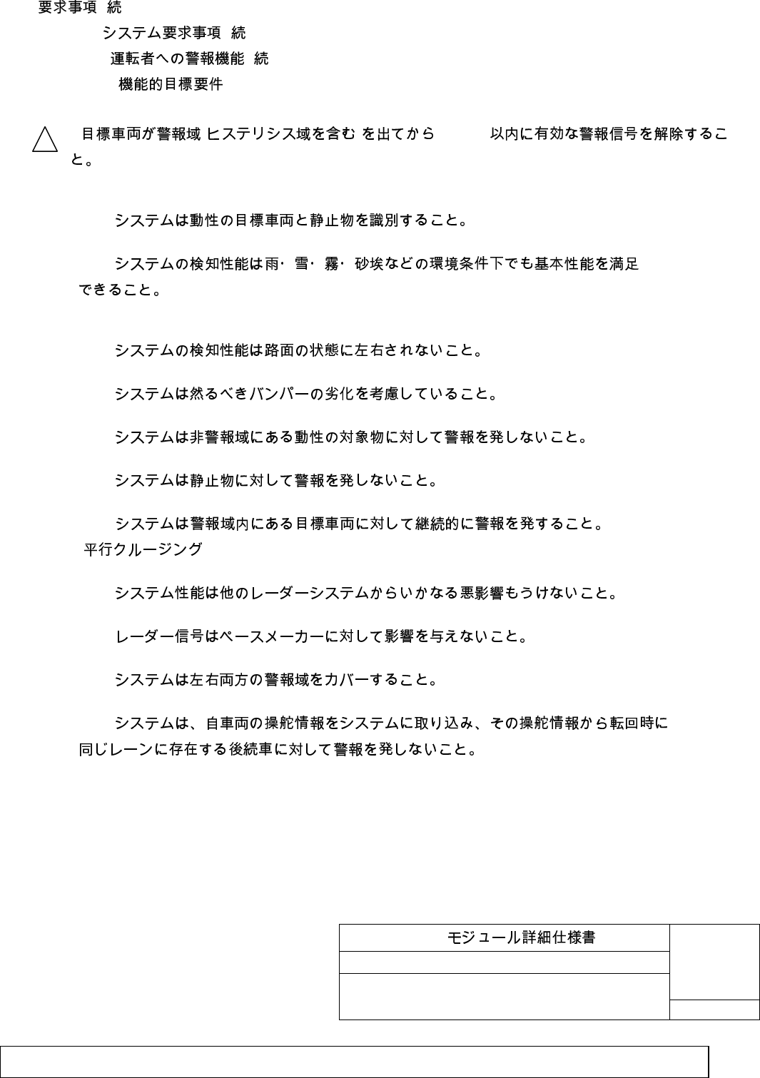
4) Functional target requirements
- ( ) 500ms
Releases valid warning signal within 500ms after the target vehicle has left the warning
zone (include the hysteresis zone).
- BSM
BSM system must distinguish between moving target vehicles and stationary objects.
- BSM
BSM system's detection performance must satisfy its basic performance by environmental
conditions such as rain, snow, fog, or sandy dust.
- BSM
BSM system's detection performance must not be affected by road surface condition.
- BSM
BSM system must consider applicable bumper deterioration (max. 1dB).
- BSM
BSM system must not warn for a moving object in non-warning zone.
- BSM
BSM system must not warn for stationary object.
- BSM
( )
BSM system must warn continuously for target vehicle in warning zone. (parallel cruising)
- BSM
BSM system performance must not be affected by other radar system whatsoever.
- BSM
BSM radar signal must not affect pace makers.
- BSM
BSM warning system must cover both left and right warning zones.
- BSM
BSM system must not warn for following vehicle existing in same lane by own vehicle's steering
information taken into own system, when own vehicle turns.
1
BSM
No. TD74 67 Y30
20/34
Customer
SHT
Filename: Exhibit_8_User_Manual.doc
Issue status: 0.1 Document maturity: draft
Department: SV SC RS DA
page
20 of 34
Copyright
by Siemens AG 2006
All rights reserved
D
r
a
f
t
3. ( ) (Requirement for the function of the BSM Modules) (continued)
3.1 BSM ( ) (BSM system requirements) (continued)
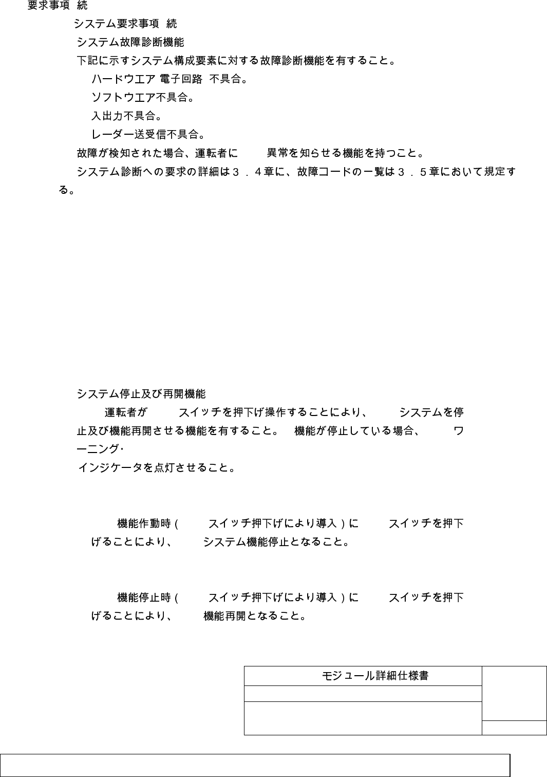
3.1.3. System trouble diagnosis function
1) ( )
2)
3)
4)
BSM
Must have the diagnostics function for the following system structure elements.
1) Hardware (electronics circuit) malfunctions.
2) Software malfunctions.
3) Input/output malfunctions.
4) Radar sending/receiving malfunctions.
BSM system must have a function to warn the driver of abnormal BSM when trouble is
detected.
The details of requirements for system diagnosis is stated in section 3.4, and trouble code
list in section 3.5.
3.1.4. System abort and resume function
BSM BSM
BSM
Must have a function to abort and resume the BSM system by pushing
down the BSM switch by the driver.
1) BSM BSM BSM
BSM
1) BSM system function shall stop when BSM switch is switched during the
system is working properly.
2) BSM BSM BSM
BSM
2) BSM system function shall resume when BSM switch is switched during the

BSM
No. TD74 67 Y30
21/34
Customer
SHT
Filename: Exhibit_8_User_Manual.doc
Issue status: 0.1 Document maturity: draft
Department: SV SC RS DA
page
21 of 34
Copyright
by Siemens AG 2006
All rights reserved
D
r
a
f
t
system function is stopped. (function stopped by this switch)
BSM
No. TD74 67 Y30
22/34
Customer
SHT
Filename: Exhibit_8_User_Manual.doc
Issue status: 0.1 Document maturity: draft
Department: SV SC RS DA
page
22 of 34
Copyright
by Siemens AG 2006
All rights reserved
D
r
a
f
t
3. BSM ( ) (Requirement for the function of the BSM Modules) (continued)
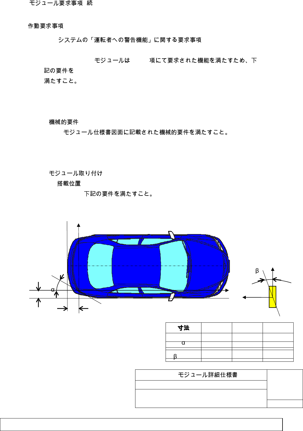
3.2. (Operation requirements)
3.2.1 BSM
3.2.1 Requirement for BSM module relating to the system "warning requirements"
BSM 3.1.2
BSM module should fulfill following requirements, in order to fulfill the
system function requirement which is written in “3.1.2”.
1) Mechanical requirement
BSM
Mechanical requirement shall fulfill the requirements in “BSM module detailed
specification”.
2) Mounting of the module
a. Mounting position
Mounting position shall be fulfilling following requirement.
min typ max
h_x 100mm 300mm 500mm
h_y 50mm 100mm 150mm
h_z 500mm 800mm 1200mm
23° 25° 27°
(J61J) 3°
-2
5°
0
7°
2
y
h_x
h_y
z
y
x
BSM
No. TD74 67 Y30
23/34
Customer
SHT
Filename: Exhibit_8_User_Manual.doc
Issue status: 0.1 Document maturity: draft
Department: SV SC RS DA
page
23 of 34
Copyright
by Siemens AG 2006
All rights reserved
D
r
a
f
t
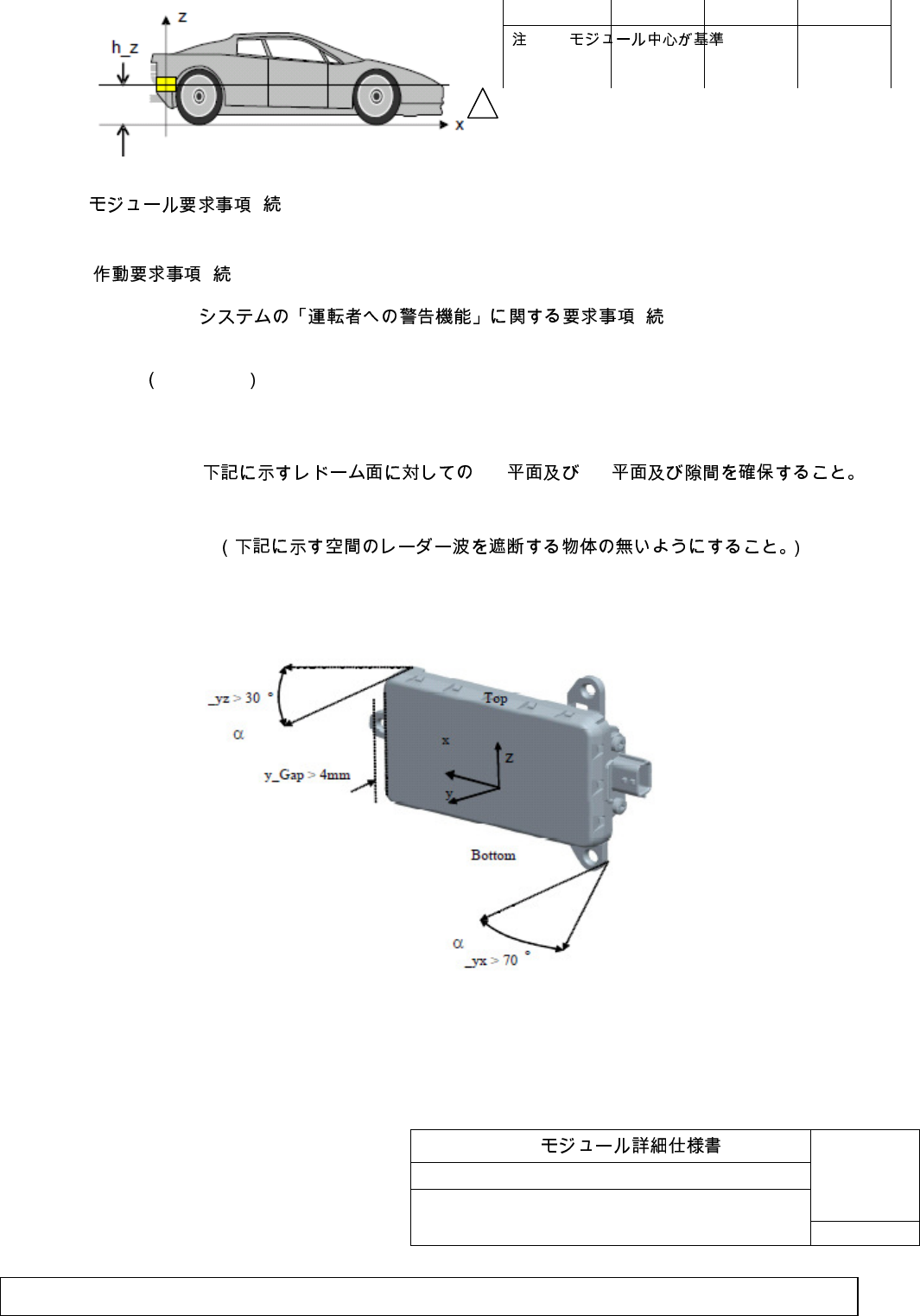
3. BSM ( ) (Requirement for the function of the BSM Modules) (continued)
3.2 ( ) (Operation requirements) (continued)
3.2.1 BSM ( )
3.2.1 Requirement for BSM module relating to the system " warning requirement "
Continued
b. Keep out zone
YX YZ
Radar signal disturbing material should not locate the keep out zone written follow.
(The object, which blocks the radar signal, should not be in the area describe below.)
Radar signal disturbing material keep out zone
(J50C8)
:BSM
Note: Reference point is center of
module
2
BSM
No. TD74 67 Y30
24/34
Customer
SHT
Filename: Exhibit_8_User_Manual.doc
Issue status: 0.1 Document maturity: draft
Department: SV SC RS DA
page
24 of 34
Copyright
by Siemens AG 2006
All rights reserved
D
r
a
f
t
3. BSM ( ) (Requirement for the function of the BSM Modules) (continued)
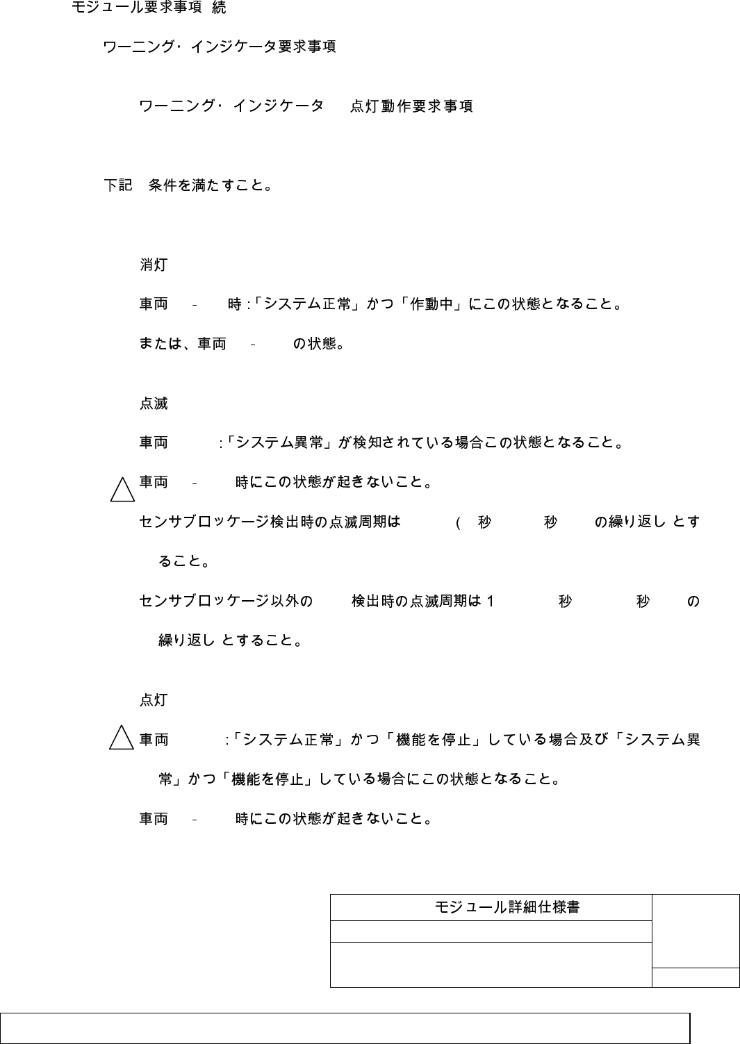
3.3. BSM (BSM warning indicator requirements)
3.3.1 BSM – (BSM warning indicator lighting
operation requirements)
3
Must fulfill the following 3 conditions.
1)
IG ON
IG OFF
2)
IG-ON
IG OFF
0.25Hz 2 ON / 2 OFF )
DTC Hz (0.5 ON / 0.5 OFF
)
3)
IG-ON
IG OFF
1) Turn off
2
1

BSM
No. TD74 67 Y30
25/34
Customer
SHT
Filename: Exhibit_8_User_Manual.doc
Issue status: 0.1 Document maturity: draft
Department: SV SC RS DA
page
25 of 34
Copyright
by Siemens AG 2006
All rights reserved
D
r
a
f
t
At vehicle IG-ON: Must be this status when "system normal" and "operation ongoing"
or at vehicle IG-OFF status.
2) Blinking
Vehicle IG-ON: Must be this status when "system abnormal" is detected.
This status must not occur at vehicle IG-OFF.
In case the sensor blockage is detected, blinking frequency should be 0.25 Hz
(Repeat 2sec ON / 2sec OFF).
In case the DTC is detected except sensor blockage, blinking frequency should be
1Hz (Repeat 0.5sec ON / 0.5sec OFF).
3) Lighting
Vehicle IG-ON: Must be this status when "system normal" and "operation aborted"
and when "system abnormal" and "operation aborted".
This must not occur at vehicle IG-OFF.
2
1
BSM
No. TD74 67 Y30
26/34
Customer
SHT
Filename: Exhibit_8_User_Manual.doc
Issue status: 0.1 Document maturity: draft
Department: SV SC RS DA
page
26 of 34
Copyright
by Siemens AG 2006
All rights reserved
D
r
a
f
t
3. Function requirements (continued)
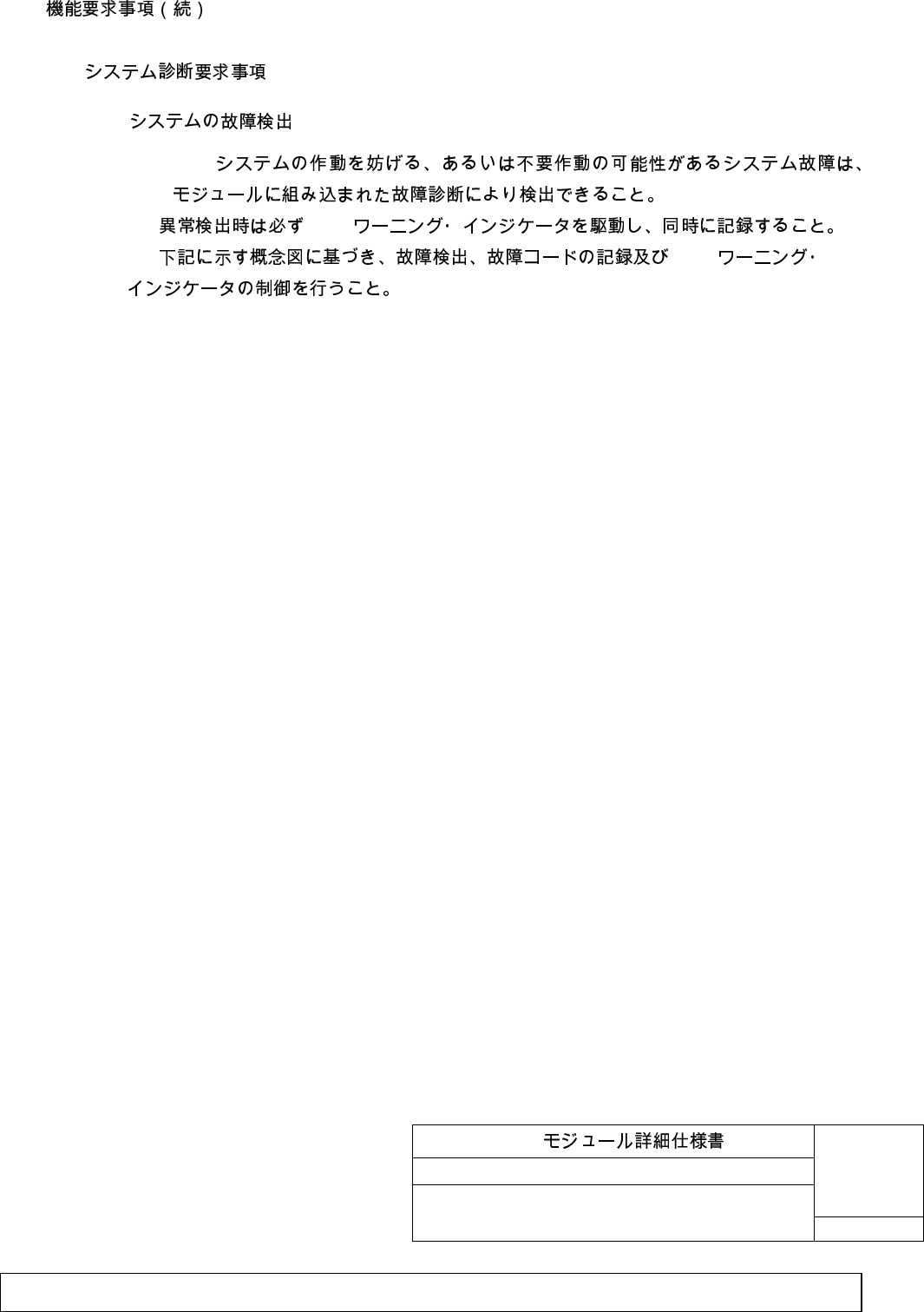
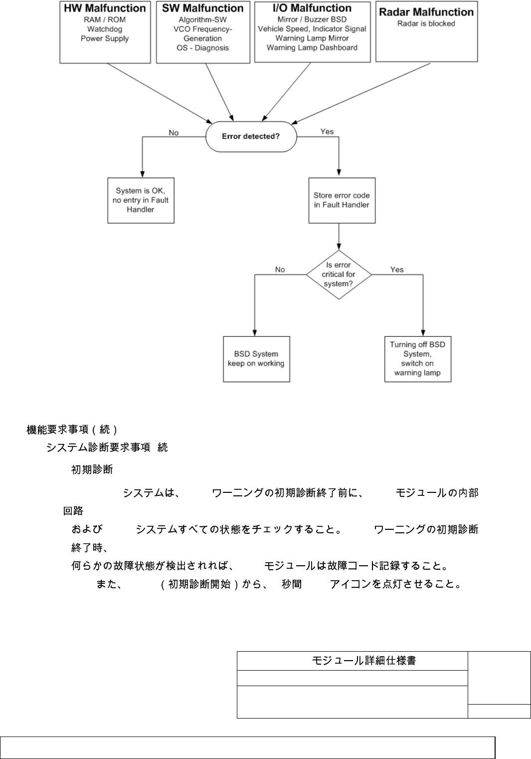
3.4. System diagnosis requirements
3.4.1. System trouble detection
BSM
BSM
BSM
BSM
Trouble diagnosis contained in BSM module must be able to detect system troubles
which possibly disturbs BSM system operation or is an unnecessary operation.
This must run BSM warning indicator and record same time when trouble is detected.
This must control trouble detection, recording of trouble code and BSM warning
indicator based on following conceptual diagram.
BSM
No. TD74 67 Y30
27/34
Customer
SHT
Filename: Exhibit_8_User_Manual.doc
Issue status: 0.1 Document maturity: draft
Department: SV SC RS DA
page
27 of 34
Copyright
by Siemens AG 2006
All rights reserved
D
r
a
f
t
3. Function requirements (continued)
3.4 ( ) System diagnosis requirements (continued)
3.4.2. Initial diagnosis
BSM BSM BSM
BSM BSM
BSM
IG-ON 3 BSM
BSM system must check the internal circuit of BSM module and all conditions of
BSM systems before completing BSM warning initial diagnosis. If any fault is detected
BSM
No. TD74 67 Y30
28/34
Customer
SHT
Filename: Exhibit_8_User_Manual.doc
Issue status: 0.1 Document maturity: draft
Department: SV SC RS DA
page
28 of 34
Copyright
by Siemens AG 2006
All rights reserved
D
r
a
f
t
when BSM warning initial diagnosis completed, BSM module must record the fault code.
BSM icon shall be turned on 3 [sec] from IG-ON. (start of the initial check)
3.5. Fault code list (Trouble code and lighting condition)
fault code and the detection condition
BSD SUBSYSTEM SPECIFIC DIAGNOSTIC
SPECIFICATION
Fault code and the detection condition are according to
”BSD SUBSYSTEM SPECIFIC
DIAGNOSTIC SPECIFICATION”
.
( ) BSM system operation prohibition condition (software)
BSM
• uC RAM
• uC ROM
BSM system must stop the warning function to the driver when following hardware
trouble is detected.
• Micro processor volatile memory trouble. (uC RAM trouble)
• Micro processor reading only memory trouble. (uC ROM trouble)
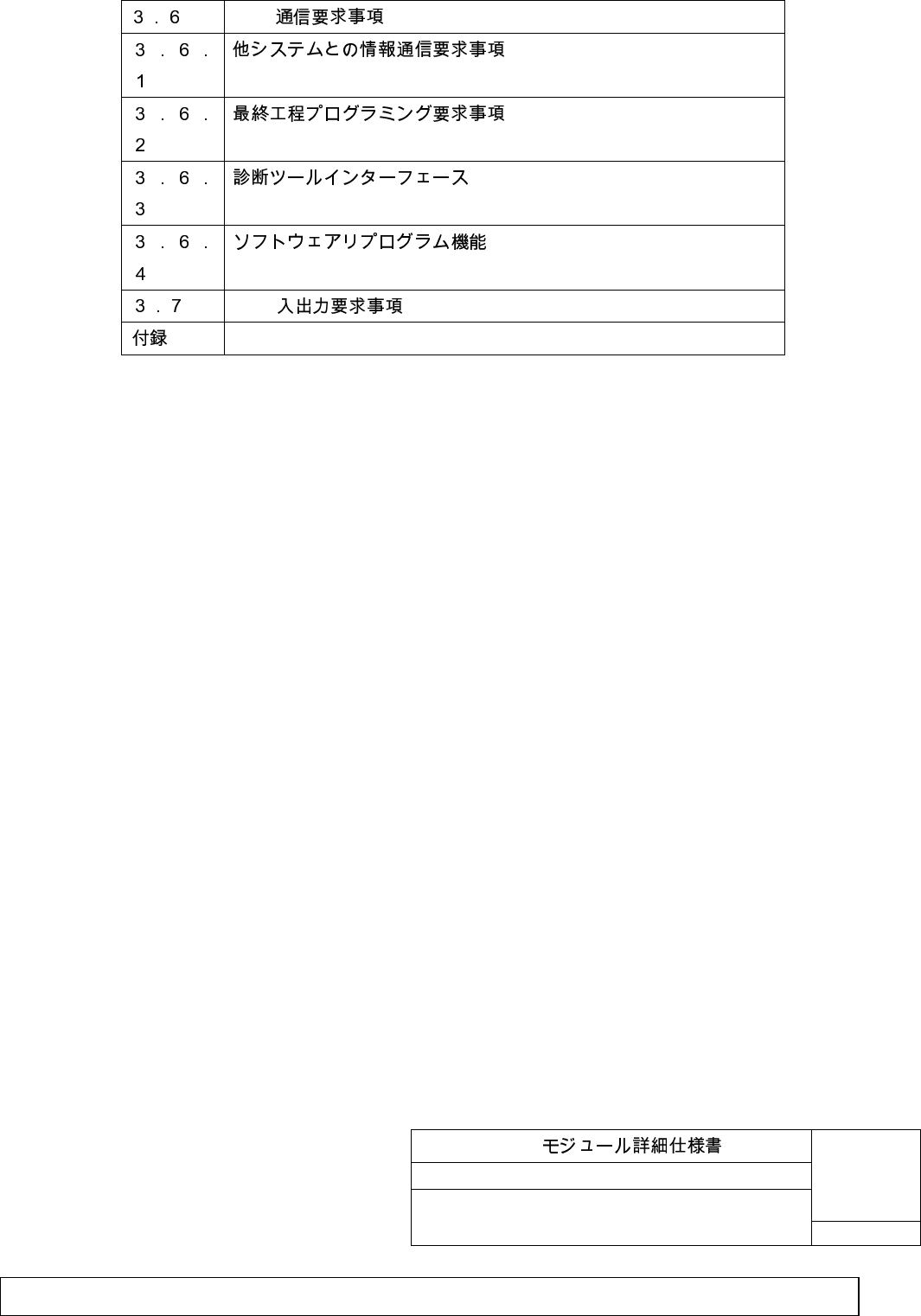
3.6. CAN CAN communication requirements
3.6.1. Requirements for information communication with other
system
BSM
1) BSM
2) BSM
3) BSM
4) BSM
5) BSM BSM
1
1
BSM
No. TD74 67 Y30
29/34
Customer
SHT
Filename: Exhibit_8_User_Manual.doc
Issue status: 0.1 Document maturity: draft
Department: SV SC RS DA
page
29 of 34
Copyright
by Siemens AG 2006
All rights reserved
D
r
a
f
t
3. Function requirements (continued)
3.6 CAN CAN communication requirements (continued)
3.6.1 Requirements for information communication
with other system (continued)
BSM module must be designed to be able to communication with other
systems on the vehicle for the following data.
1) Own vehicle speed. (input to BSM system)
2) Left and right turn switch signal. (input to BSM system)
3) Steering angle data. (input to BSM system)
4) Buzzer on / off .(output from BSM system)
5) BSM warning indicator on / off .(output from BSM system)
3.6.2. Final process programming requirements
BSM
BSM module must be designed to accept the following data at EOL of final
process at vehicle body assembly plant.
1) Configuration ( ) CAN
2) EOL EOL BSM
BSM
1) Configuration using the CAN communication based on the Configuration requirement
specification GGDS. (vehicle series)
2) EOL function confirmation: BSM module having function to confirm the BSM system
function by EOL function confirmation method stated in attachment .
3.6.3. Diagnosis tool interface
BSM
CAN GGDS Version Da: SD-
CSS67560-57-Da
CAN
BSM Ford Global Generic Diagnostic Specification
Part1
DTC
1
BSM
No. TD74 67 Y30
30/34
Customer
SHT
Filename: Exhibit_8_User_Manual.doc
Issue status: 0.1 Document maturity: draft
Department: SV SC RS DA
page
30 of 34
Copyright
by Siemens AG 2006
All rights reserved
D
r
a
f
t
BSM module must support the CAN trouble diagnosis communication stated in "CAN
Trouble diagnosis spec - GGDS correspondence:
Version Da: SD-CSS67560-57-Da
".
BSM module must support diagnosis requirement defined in "Ford Global Generic
Diagnostic Specification (GGDS) Part1". Supplier must develop the part2 specification
specifically for application.
3. Function requirements (continued)
3.6 CAN CAN communication requirements (continued)
3.6.3 Diagnosis tool interface (continued)
Recorded detailed trouble code (DTC) must not be physically deleted from memory
under any circumstance.
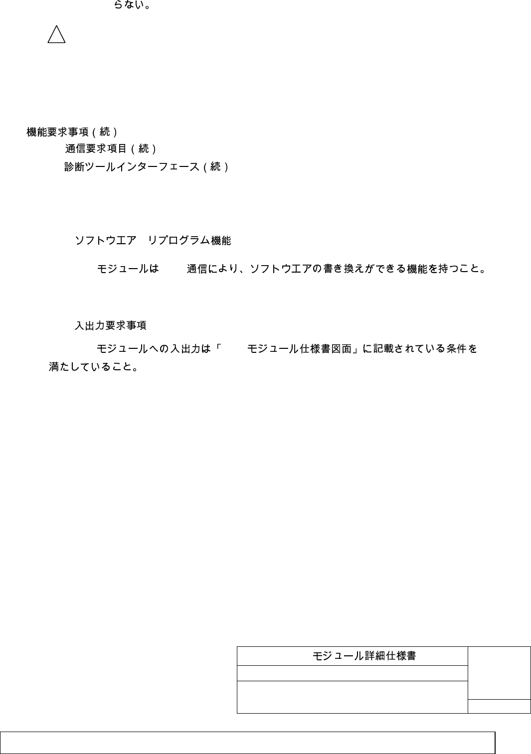
3.6.4. Software reprogramming Function
BSM CAN
BSM module shall have the reprogram function by CAN communication.
3.7. BSM BSM input/output requirements
BSM BSM
Input/output to BSM module must fulfill the conditions on "BSM module specification
drawing".
1
BSM
No. TD74 67 Y30
31/34
Customer
SHT
Filename: Exhibit_8_User_Manual.doc
Issue status: 0.1 Document maturity: draft
Department: SV SC RS DA
page
31 of 34
Copyright
by Siemens AG 2006
All rights reserved
D
r
a
f
t
EOL Test Setup (Outline)
After the installation of the BSM modules the vehicle is located in an assembly line with several
objects within the field of view of the sensor.
For a basic functional test of the BSM system objects in the field of view of the sensor, or test
objects placed in the field of view may be used as target.
The test procedure of the sensor comprises the emission and reception of the 24 GHz radiation
separately for the two beams.
The successful detection of objects at a position with a tolerance is a perfect test for the principal
functionality of the sensor and the communication interface to the vehicle.

BSM
No. TD74 67 Y30
32/34
Customer
SHT
Filename: Exhibit_8_User_Manual.doc
Issue status: 0.1 Document maturity: draft
Department: SV SC RS DA
page
32 of 34
Copyright
by Siemens AG 2006
All rights reserved
D
r
a
f
t