Contrinex RFM30HF RFID Transponder Reader User Manual Users manual 3
Contrinex AG RFID Transponder Reader Users manual 3
Contents
- 1. Users manual 1
- 2. Users manual 2
- 3. Users manual 3
- 4. Users manual 4
Users manual 3
CONTRINEX AG Industrial Electronics route du Pâqui 5 - P.O. Box - CH 1720 Corminboeuf - Switzerland - Tel: +41 26 460 46 46 -
Fax: +41 26 460 46 40 - Internet: www.contrinex.com - E-mail: info@contrinex.com
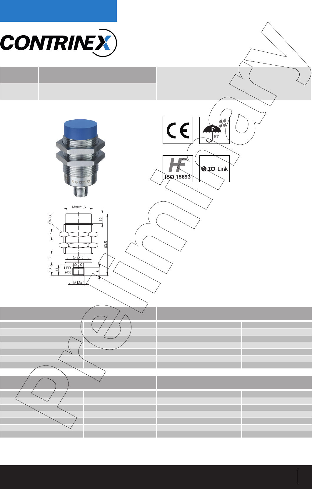
HF RFID SYSTEM
READ/WRITE MODULES (RWM)
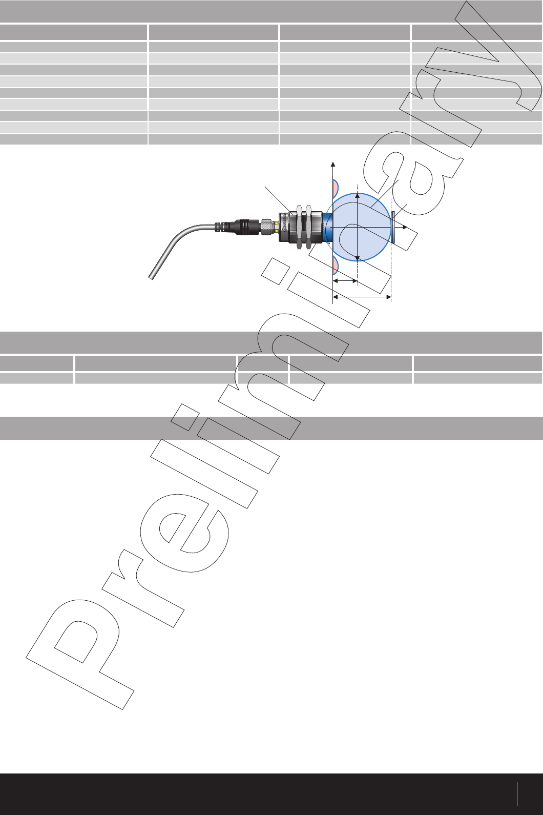
1
HOUSING READ/WRITE DISTANCE
M30 62.5 mm*
GENERAL DATA INTERFACE
Carrier frequency 13.56 MHz Data transfer rate 38 400 baud
Compatible standard ISO 15693 LED green on RWM live
Maximum transmission speed 26.5 kbit/s LED green blinking IO-Link communication
Read-write distance max. 62.5 mm with RTP-0502-022 LED yellow on Transponder detected
LED yellow blinking Transponder + IO-Link
communication
IO-Link ü
RLS-1301-320
ü M30 Metal threaded housing
ü Sensing face of PBTP
ü Insensitive to dirt
ü IO-Link V1.1
ELECTRICAL DATA MECHANICAL DATA
Supply voltage range (Ub) 11...32 VDC Protection degree IP67
No-load supply current (field off) 20 mA Ambient temperature range TA** -25...+80 °C
Max. current consumption (no load) 50 mA Storage temperature range TS*** -25...+80 °C
Polling current 30 mA Sensing face material PBTP
Short-circuit protection üHousing material Chrome-plated brass
Voltage reversal protection üConnector type M12 4-pin
Max. output current ≤ 200 mA Weight (incl. nuts) 87 g
* Please refer to table page 8
ü 2 x PNP output in SIO
mode configurable
ü RWM reconfigurable via
a Master Tag
** Read/write operations possible
*** Data retention and mechanical stability limit
CONTRINEX AG Industrial Electronics route du Pâqui 5 - P.O. Box - CH 1720 Corminboeuf - Switzerland - Tel: +41 26 460 46 46 -
Fax: +41 26 460 46 40 - Internet: www.contrinex.com - E-mail: info@contrinex.com
2
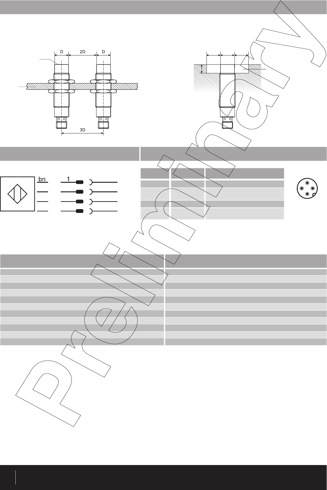
MOUNTING RECOMMENDATIONS
WIRING DIAGRAM PIN ASSIGNMENT
PIN SIGNAL FUNCTION
1 L+ +24 V
2 Q2 DO (tag presence or data com-
parison)
3 L- OV
4 C/Q1 SDCI/SIO (tag presence or data
comparison)
3
1
4
2
M12
CLEARANCE
Read/write modules must not mutually influence each other. For this reason, a minimum distance of 2 x D between the devices must be observed.
DDD
10
mm
sensing face
support
metal free zone
IO-LINK CHARACTERISTICS VALUE FOR RLS-1301-320
IO-Link Protocol 1.1
COM-Mode COM2 (38.4 kBaud)
Min. cycle time 14.4 ms
Process data width in 9 bytes
Process data width out 10 bytes
Profile Smart Sensor Profile
SIO-Mode support Yes
Port type A
Memory request for data management 41 bytes
Device ID 0xAB0300
Vendor ID 0x0156
bk 4C/Q1
bu 3 L-
L+
wh 2 Q2
CONTRINEX AG Industrial Electronics route du Pâqui 5 - P.O. Box - CH 1720 Corminboeuf - Switzerland - Tel: +41 26 460 46 46 -
Fax: +41 26 460 46 40 - Internet: www.contrinex.com - E-mail: info@contrinex.com 3
CONFIGURATION PARAMETER (IO-LINK / SIO MODE)
Index Sub Hex Name Access Data Type Value Default
IDENTIFICATION
10hVendor Name R char [] “Contrinex“
11hVendor Text R char [] “www.contrinex.com“
12hProduct Name R char [] “RLS-1301-320“
13hProduct ID R char [] “00000000“
14hProduct Text R char [] “IO-Link RFID reader“
15hSerial Number R char [] “00000001“
17hFirmware Revision R char [] “01.09.01“
18hApplication Specific Tag R/W char [] <user string, 16 byte (variable length)> <vendor spe-
cific>
READER PARAMETER PROCESS DATA
40h01hOperating Mode R/W uint8
FFh : Scan UID
00h : Scan User Data
01h : Read / Write Command
FFh
02hData Hold Time R/W uint8
FFh : No Hold Time
00h : Hold Time 100 ms
01h : Hold Time 200 ms
02h : Hold Time 500 ms
03h : Hold Time 1000 ms
04h : Hold Time 2000 ms
FFh
03hScan Address R/W uint8 Address to scan FFh
READER PARAMETER SIO
41h01h
C/Q1 PIN SIO Operating
Mode R/W uint8
FFh : Presence Transponder
00h : Compare Data
01h : No SIO
FFh
02hC/Q1 SIO Data to compare H R/W uint32 Comparison value Byte 7 to 4 FFh, FFh,
FFh, FFh,
03hC/Q1 SIO Data to compare L R/W uint32 Comparison value Byte 3 to 0 FFh, FFh,
FFh, FFh,
04h
SIO Compare Data Address
(C/Q1 & Q2) R/W uint8 Comparison address for C/Q1 and Q2 (A valid
address must be chosen) FFh
05h
Data Hold Time Output
(C/Q1 & Q2) R/W uint8
FFh : No Hold Time
00h : Hold Time 100 ms
01h : Hold Time 200 ms
02h : Hold Time 500 ms
03h : Hold Time 1000 ms
04h : Hold Time 2000 ms
FFh
06hC/Q1 PIN SIO Polarity R/W uint8 FFh : Output “close” if condition = true
00h : Output “open” if condition = true FFh
07hQ2 PIN SIO Operating Mode R/W uint8
FFh : Presence Transponder
00h : Compare data (C/Q1 must be also in com-
pare data)
01h : No SIO
FFh
08hQ2 SIO Data to compare H R/W uint32 Comparison value Byte 7 to 4 FFh, FFh,
FFh, FFh,
09hQ2 SIO Data to compare L R/W uint32 Comparison value Byte 3 to 0 FFh, FFh,
FFh, FFh,
0AhQ2 PIN SIO Polarity R/W uint8 FFh : Output “close” if condition = true
00h : Output “open” if condition = true FFh

CONTRINEX AG Industrial Electronics route du Pâqui 5 - P.O. Box - CH 1720 Corminboeuf - Switzerland - Tel: +41 26 460 46 46 -
Fax: +41 26 460 46 40 - Internet: www.contrinex.com - E-mail: info@contrinex.com
4
PROCESS DATA OUTPUT
N_ANT : 0 = Switch on RF field
1 = Switch off RF field
TAG NB : Index of tag to be printed in UID area
(index from 0)
RDY : 0 = No data available yet
1 = Memory scanned and data available
ERR : 0 = Memory scanned and no error
1 = Memory scanned but error;
TAG : 0 = No tag present in front of the RWM
1 = Tag present in front of the RWM
ANT : 0 = RF field off
1 = RF field on
EXT : 0 = 4 bytes data
1 = 8 bytes data
Data 0 : User data LSB / Error Code
Data 3 / 7 : User data MSB
PROCESS DATA INPUT
PROCESS DATA MODE SCAN USER DATA
PROCESS DATA REPRESENTATION
PROCESS DATA INPUT
TAG : 0 = No tag present in front of the RWM
1 = 1 tag or more present in front of the RWM
ANT : 0 = RF field off
1 = RF field on
NB TAG : Number of tag in front of the RWM
UID 0 : UID LSB
UID 7 : UID MSB
PROCESS DATA MODE SCAN UID MODE
Bitoffset
TAG ANT NB TAG
UID 0
UID 1
UID 2
UID 3
UID 4
UID 5
UID 6
UID 7
7 6 5 4 3 2 1 0
0
1
2
3
4
5
6
7
8
Bitoffset
N_ANT TAG NB
7 6 5 4 3 2 1 0
0
1
2
3
4
5
6
7
8
9
Bitoffset
RDY ERR TAG ANT EXT
Data 0 / Error Code
Data 1
Data 2
Data 3
Extended Data 4
Extended Data 5
Extended Data 6
Extended Data 7
7 6 5 4 3 2 1 0
0
1
2
3
4
5
6
7
8
N_ANT : 0 = Switch on RF Field
1 = Switch off RF Field
PROCESS DATA OUTPUT
Bitoffset
N_ANT
7 6 5 4 3 2 1 0
0
1
2
3
4
5
6
7
8
9

CONTRINEX AG Industrial Electronics route du Pâqui 5 - P.O. Box - CH 1720 Corminboeuf - Switzerland - Tel: +41 26 460 46 46 -
Fax: +41 26 460 46 40 - Internet: www.contrinex.com - E-mail: info@contrinex.com 5
PROCESS DATA OUTPUT
RDY : 0 = No data available yet
1 = Command executed and data available
ERR : 0 = Command executed and no error
1 = Command executed but error
TAG : 0 = No tag present in front of the RWM
1 = Tag present in front of the RWM
ANT : 0 = RF field off
1 = RF field on
EXT : 0 = 4 bytes data
1 = 8 bytes data
Data 0 : Read data LSB / Error Code
Data 3 / 7 : Read data MSB
PROCESS DATA INPUT
PROCESS DATA MODE READ/WRITE
START : 0 = Do not execute the command
1 = Execute the command
N_ANT : 0 = Switch on RF Field
1 = Switch off RF Field
CMD : 0 = No command
1 = Read
2 = Write
EXT : 0 = 4 bytes data
1 = 8 bytes data
ADD : Block address
Data 0 : Write data LSB
Data 3 / 7 : Write data MSB
Error Code Definition
CommandNotSupported = 1,
FormatError = 2,
OptionNotSupported = 3,
CommandProblem = 5,
CommTagError = 6,
TagError = 15,
NoMomoryBloc = 16,
BlocProtected = 18,
Bitoffset
RDY ERR TAG ANT EXT
Data 0 / Error Code
Data 1
Data 2
Data 3
Extended Data 4
Extended Data 5
Extended Data 6
Extended Data 7
7 6 5 4 3 2 1 0
0
1
2
3
4
5
6
7
8
Bitoffset
START N_ANT CMD EXT
ADD
Data 0
Data 1
Data 2
Data 3
Extended Data 4
Extended Data 5
Extended Data 6
Extended Data 7
7 6 5 4 3 2 1 0
0
1
2
3
4
5
6
7
8
9
*always do a reset after the restore of factory settings
SYSTEM COMMAND (idx 02h)
Value hex Value dec Function
05h5 ParamDownloadStore
80h128 Device Reset
82h130 Restore factory settings*
CONTRINEX AG Industrial Electronics route du Pâqui 5 - P.O. Box - CH 1720 Corminboeuf - Switzerland - Tel: +41 26 460 46 46 -
Fax: +41 26 460 46 40 - Internet: www.contrinex.com - E-mail: info@contrinex.com
6
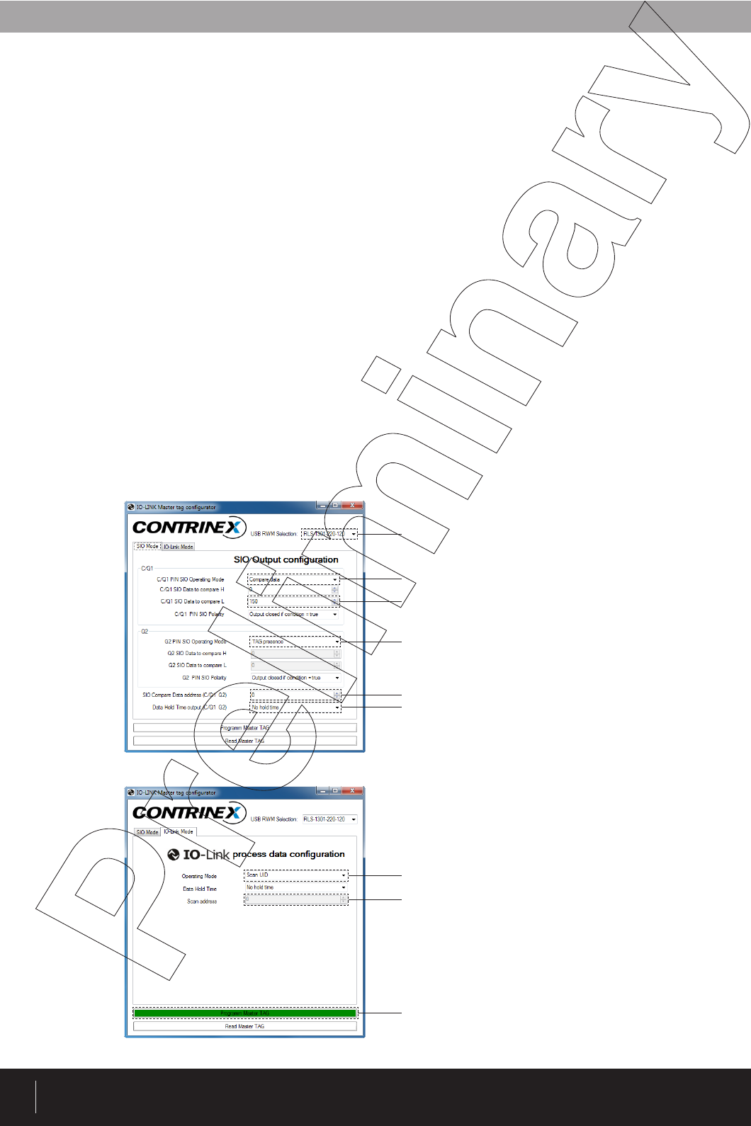
MASTER TAG CONFIGURATION
For the RLS-1301-320, the IO-Link mode or the SIO (standard I/O mode) can be configured via IO-Link or via a Master Tag.
For the configuration via a Master Tag, a transponder (called Master Tag) will contain all the data used for the configuration.
There is a simple procedure to configure the RWM. Once all the data are written in the Master Tag, you need to put it in front of the RWM sensing face,
to switch off the RWM power supply and to switch on again. The RWM will detect that it’s a Master Tag and read all the data and configure the outputs
accordingly.
On the Contrinex RFID product finder page (https://www.contrinex.com/product-finder/rfid/) of any ContriNET RWM USB, it is possible to download a
software to setup the Master Tag using a ContriNET RWM USB. This program is called “IO-Link Master Tag Programmer” and its it is included in the
“Softwares” zip file.
SIO MODE POSSIBILITIES
If you use the RLS-1301-320 in an SIO mode, you will have two main possibilities:
1. Presence Transponder:
In this mode, the output will switch if a transponder is in the field of the RWM.
2. Compare Data:
In this mode, the output will switch if the data red in the defined block memory of the transponder matches with the data stocked in the RWM.
MASTER TAG
To build a Master Tag it’s possible to use any ISO15693 chip with at least eight memory blocks with 32 bits each. Two screenshots of the “IO-Link
Master Tag Programmer” are placed below to serve as an example of one possible Master Tag configuration
Read/Write Module used
Compare data value (DEC) to switch output C/Q1
Output switch condition selection for Q2 (Tag presence)
Tag memory address value (DEC) where to perform the compare data operation
When Tag Master data (SIO & IO-Link Mode) is successfully programmed in to the tag
memory, the "Program Master TAG" button turns green , otherwise it turns red
Selection box for the IO-Link operation mode (Scan UID, Scan User Data and Scan Read/
Write Command)
Scan address where to read the RFID data (only available when Scan User Data mode is
selected)
Timer value during which the switching state is maintained after the transponder left the
RWM detection range
Output switch condition selection for C/Q1 (Compare data)
CONTRINEX AG Industrial Electronics route du Pâqui 5 - P.O. Box - CH 1720 Corminboeuf - Switzerland - Tel: +41 26 460 46 46 -
Fax: +41 26 460 46 40 - Internet: www.contrinex.com - E-mail: info@contrinex.com 7
RLS-1301-320_171205_YAG
AVAILABLE TYPES
Part number Part reference Ø Mounting Connection
720 100 207 RLS-1301-320 M30 Non-embeddable M12 4-pin
FCC information
This device complies with part 15 of the FCC rules. Operation is subject to the following two conditions:
(1) This device may not cause harmful interference, and
(2) this device must accept any interference received, including interference that may cause undesired operation.
Caution: Any changes or modifications not expressly approved by the party responsible for compliance could void the user’s authority to operate the
equipment.
Note:This equipment has been tested and found to comply with the limits for a Class A digital device, pursuant to part 15 of the FCC Rules. These
limits are designed to provide reasonable protection against harmful interference when the equipment is operated in a commercial environment. This
equipment generates, uses, and can radiate radio frequency energy and, if not installed and used in accordance with the instruction manual, may
cause harmful interference to radio communications. Operation of this equipment in a residential area is likely to cause harmful interference in which
case the user will be required to correct the interference at his own expense.
IC information
This device complies with Industry Canada licence-exempt RSS standard(s). Operation is subject to the following two conditions:
(1) This device may not cause interference, and
(2) this device must accept any interference, including interference that may cause undesired operation of the device.
Le présent appareil est conforme aux CNR d`Industrie Canada applicables aux appareils radio exempts de licence. L`exploitation est autorisée aux
deux conditions suivantes :
(1) L`appareil ne doit pas produire de brouillage, et
(2) l’utilisateur de l`appareil doit accepter tout brouillage radioélectrique subi, même si le brouillage est susceptible d`en compromettre le fonctionne-
ment.
Contrinex information
Operators of the products we supply are responsible for compliance with measures for the protection of persons. The use of our equipment in applica-
tions where the safety of persons might be at risk is only authorized if the operator observes and implements separate, appropriate and necessary
measures for the protection of persons and machines. Terms of delivery and rights to change design reserved.
DISCLAIMERS
POSSIBLE COMBINATION AND TYPICAL DISTANCE - RLS-1181-320
Transponder type Smax S0D0
Ø 9 RTP-0090-020 16 5 22
Ø 16 RTP-0160-020 36 17 38
Ø 20 RTP-0201-020 26 10.5 31
Ø 26 RTP-0263-020 34 15.5 37
Ø 30 RTP-0301-020 36 15.5 41
Ø 50 RTP-0501-020 47 20 54
Ø 50 RTP-0502-022 62.5 29.5 66
Ø 50 RTP-0502-062 61 28.5 65
Ø 50 RTP-0502-082 59 27.5 63
R
L
L
S
-
-
1
3
3
0
1
1
-
0
0
0
0
D0
S0
x
y
Smax
Read/Write Module Working area
Transponder