Controlled Entry Distributors DOL1000-MF2 Remote Controller User Manual Print
Controlled Entry Distributors, Inc. Remote Controller Print
Users Manual
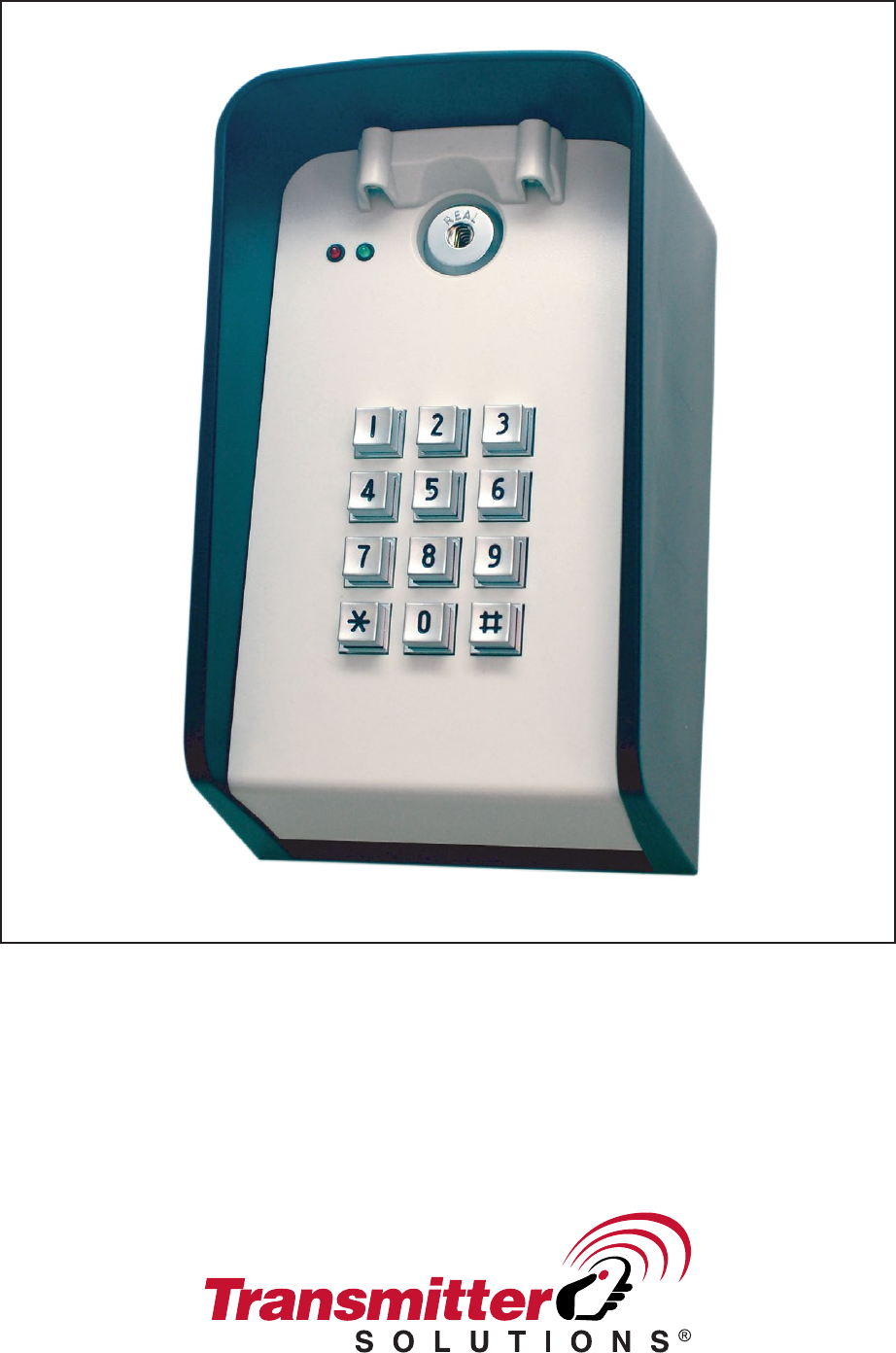
DOL1000-MF2 (2 Relay)
Programming & Installation Manual
INTRODUCTION
The DOL1000-MF2 is a versatile keypad that has the option of running wirelessly. The DOL1000- MF2
can work with 6 volts of battery power or 6-24 volts of AC/DC. This keypad can be wired with
multiple wireless transmitters. DOL1000-MF2 can store up to 1000 access codes. Guest access
codes are also programmable, which are single-use codes for access. After 5 successive incorrect
codes, the keypad will lock for 4 minutes
CONNECTION TERMINALS
• V+/V-: These terminals will supply power to the transmitter.
• ANT: Antenna
• RF1-4: The DOL1000-MF2 can control up to 4 different channels. Each RF terminal represents
a different channel.
• GO: Connects to the green LED
• NOGO: Connects to the red LED
• KEYPADUTE: Connects to the DOL1000-MF2 lights located in front of the keypad
• NO (Normally open): Use N.O. for equipment that requires a temporary surge of electricity to
activate. Example, Electric door locks, automated gates, push plates, etc.
• COM: Common ground
• NC (Normally closed): Use N.C. for equipment that requires a constant flow of electricity to
function properly. Example, Magnetic locks, receivers, etc.
• BATTERY 6VDC: If deciding to power the DOL1000-MF2 with a battery, then connect the
battery to these terminals.
• 6-24VAC/DC: If deciding to hardwire the DOL1000-MF2 directly to a power source, use these
terminals.
• Master Reset Button: Holding this button down for 5 seconds after reconnecting the keypad
to its power source will make the keypad beep 3 times. This will indicate that the Master Code
has been reset to 1234.
RESETTING THE KEYPAD AND MASTER CODE
Located on the DOL1000-MF2’s circuit board, the red Master Reset Button is used to reset the master
code back to 1234. The following steps will reset the master code:
1. Remove the battery or eliminate the power source to the DOL1000-MF2 and wait for 30
seconds for the keypad to completely power off.
2. Press and hold the red Master Reset Button.
3. While holding the red Master Reset Button, reconnect the battery or power source to the
DOL1000-MF2.
4. Continue to hold the red Master Reset Button until the keypad beeps 3 times. This will
indicate that the Master Code has been reset to 1234.
The very first time that you apply powewr to the keypad, you will hear a series of beeps followed by
a regular repeating beep (1 beep at 3 second intervals) that lets you know you are in programming
mode:
Enter a 4 digit Master Code that only you will use for programming purposes.
Write Master Code here
You can now add up to 1000 access codes as well as a flash code (for one use only) and a latch
code to hold open the gate.
To add Access Code
1934
To add Access Codes
2413, 888 and 9743
(you may add up to 1000
different codes)
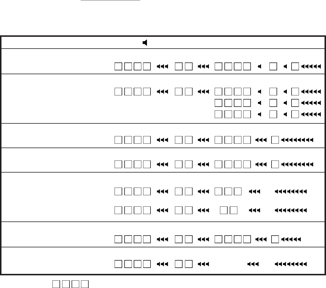
Example - Master Code 1234
Access Code:
Master Code
1 2 3 4 1 9 3 4
Sub Mode Access Code Channel Exit
1 # 1 #
To remove Access Code
1934
Master Code
1 2 3 4 1 9 3 4
Sub Mode Access Code Exit
2 # #
To change Master Code
from 1234 to 4321
Master Code
1 2 3 4 4 3 2 1
Sub Mode New Master Code Exit
7 # #
To clear all Access, Flash
and Latch codes
Master Code
1 2 3 4
Sub Mode
8 #
To add Flash Code 4437
(for one use only)
Master Code
1 2 3 4 4 4 3 7
Sub Mode Flash Code Channel
3 # 1
To set relay output time
15 seconds (1/2 - 60 seconds)
Master Code
1 2 3 4 1 5 #
Sub Mode # Seconds
5 #
To set relay output time
1/2 second 1 2 3 4 0 # 5 #
Master Code
1 2 3 4 2 4 1 3
Sub Mode Access Code Channel Exit
1 # 2 #
8 8 8 8 3 #
9 7 4 3 4 #
beep -
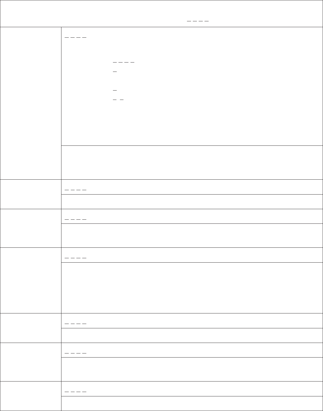
Default Master Code: 1 234
Add Access
12 3 4, 1#, Access Code: __ __ __ __ , Channel:1 #
Example:
STEP 1: Press 1 2 3 4
STEP 2: Press 1 #
STEP 3: Enter access code __ __ __ __
STEP 4: Press 1 # (multiple beeps confirm)
STEP 5: Press * *
STEP 6: Test new access code. __ __ __ __ (Green light will flash 6 times
confirming that the new access code has been accepted.)
STEP 8: Proceed to program the keypad to the receiver.
STEP 7: Install 433 MHz wireless module (see next page)
Codes
Use Channel 1 if unsure. The different channels are dependent on the RF
terminal used. Any channel can be assigned for devices that connect to normally
open/normally closed.
1 2 3 4, 2#, Access Code: __ __ __ __ , #
Remove Access
Codes Enter the Access Code you would like to delete.
1 2 3 4, 3#, Guest Code: __ __ __ __ , Channel:1
Add Guest Code The Guest Code is a one-time use access code. Once used, the number will be
cleared from memory.
1 2 3 4, 4#, Toggle Code: __ __ __ __ , Channel:1
Add Access
Toggle Code Entering Access Toggle Code will toggle the keypad to continuously activate.
Entering the code again will toggle the keypad off. Dip switch #6 on the circuit
board needs to be in the off position in order for this mode to work.
TOGGLE MODE ONLY FOR USE WHEN KEYPAD IS HARD WIRED.
1 2 3 4, 5#, Seconds:0-60, #
Set Relay
Output Time Set the number of seconds the device will grant access before locking again.
1 2 3 4, 7#, Master Code: __ __ __ __ , #
Change Master
Code Changes Master Code. If the Master Code is forgotten, this manual contains
instructions on how to reset the Master Code.
1 2 3 4, 8#
Clear All Codes
This will clear all data except the Master Code.
PROGRAMMING THE DOL1000-MF2 with 433 MHz Module
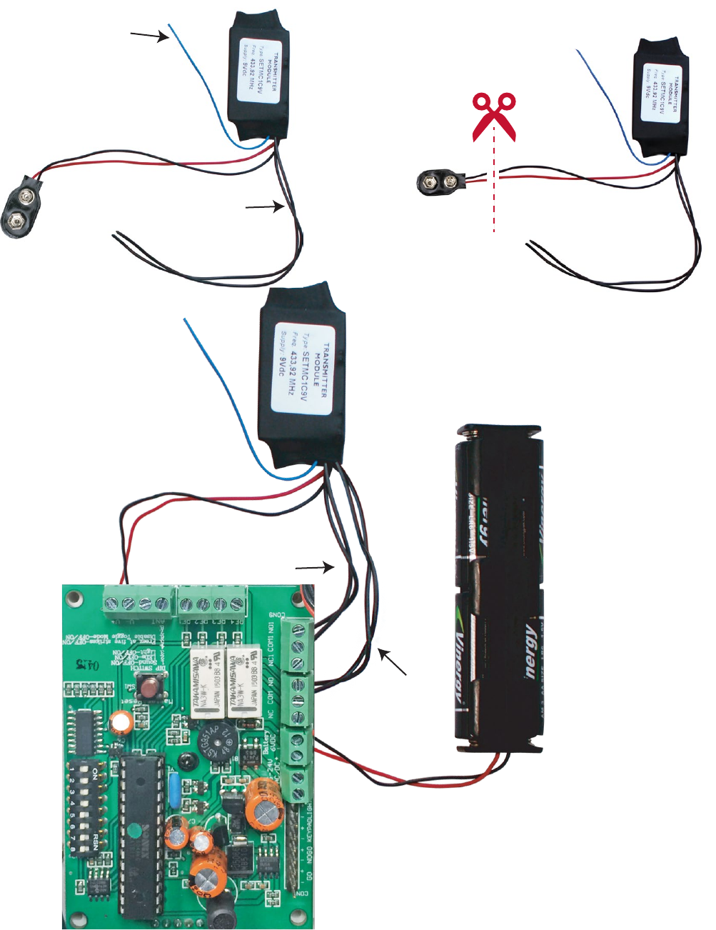
INSTALLING THE 433 MHz MODULE
Antenna
Activation Wires:
Common & Normally Open
+
-
Channel 1
Channel 2
STEP1:
Prepare the 433 MHz module
STEP2:
Remove (cut) the battery connector
• NOTE: Be sure to connect the power source to
the correct terminals! The battery terminals
and the AC/DC terminals are different.
• NOTE: Any channel can be assigned for devices
that connect to normally open/normally
closed.
STEP 3: Install the
433 MHz Module
to the keypad board
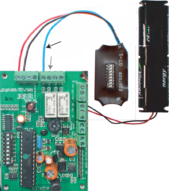
DIP SWITCH MODULE INSTALLATION EXAMPLE:
NOTE: Be sure to connect the power source to the correct terminals! The battery terminals
and the AC/DC terminals are different.
Relay 1
Relay 2
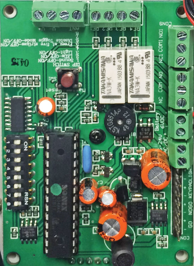
DIP SWITCHES
1. SOUND
2. LED
3. LIGHTS
4. Not used
5. Not used
6. WIRELESS MODE
a. Switching this dip switch to off will enable the toggle gate feature and switching to the
on position will disable the toggle gate feature. Disabling this feature can potentially
save battery power in the case that the toggle gate feature has been accidentally
activated. Refer to the programming chart for more details with the toggle gate feature.
7. Not used
8. Not used
Channel 1
Channel 2