Coulisse ABC06 Tubular Motor User Manual ABC 0607MC A R0 indd
Coulisse B.V. Tubular Motor ABC 0607MC A R0 indd
UserManual.wiki
>
Coulisse
>
ABC06 User Manual
User Manual
Navigation menu
Upload a User Manual
Namespaces
Wiki Guide
HTML
PDF
Info
Views
User Manual
Discussion / Help
Navigation
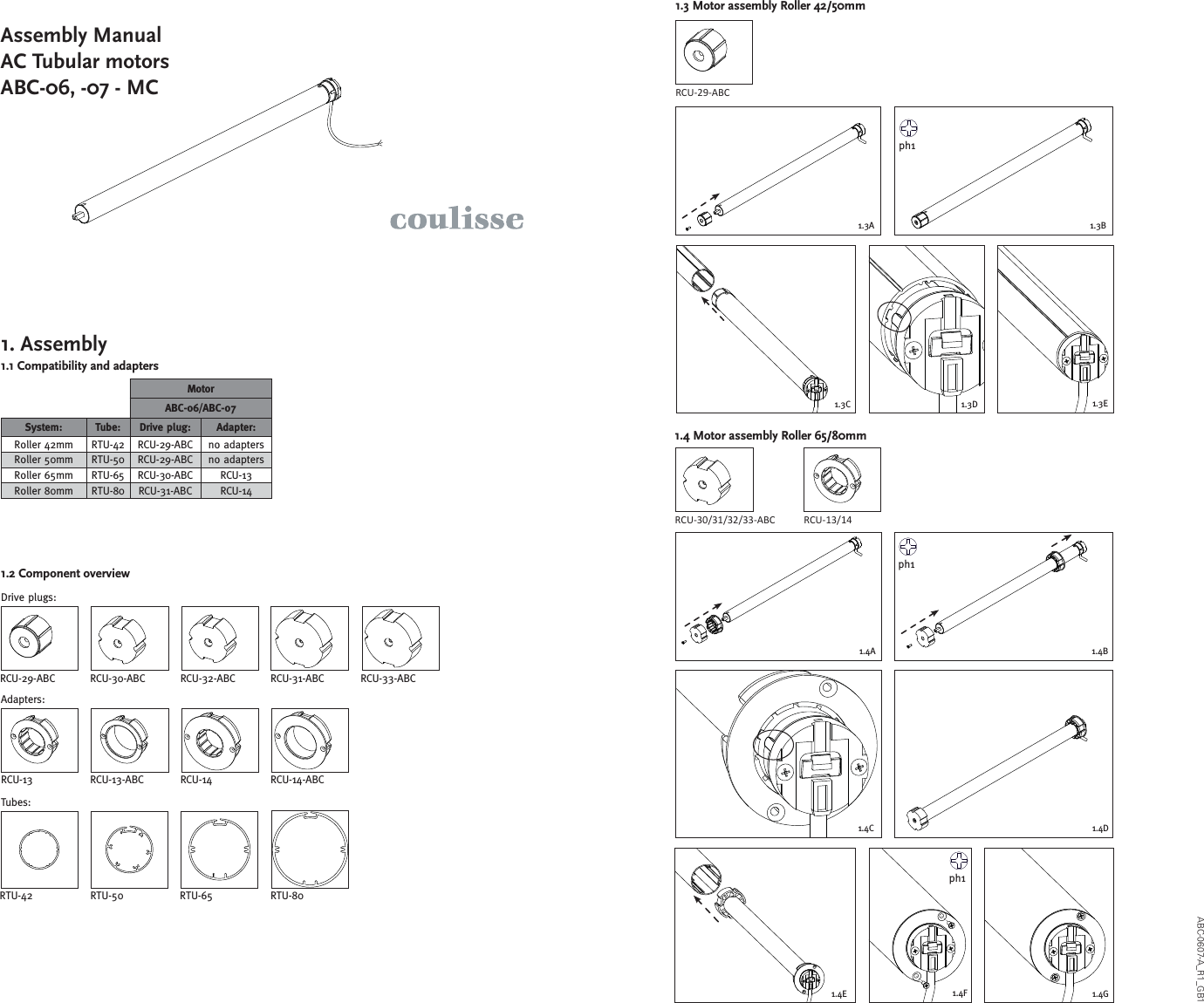
![indoor use onlyL3L2ØD1L1!Coulisse B.V., Vonderweg 48, 7468 DC Enter, The Netherlands!ABC-0607MC-U_R1_User ManualAC Tubular motorsABC-06, -07 - MC(120)WARNING: Important safety instructions. Follow all instructions, since incorrect installation can lead to severe injury.Do not make repairs yourself. Do not attempt to open the device or disassemble it. You run the risk of electric shock and voiding the limited warranty. No user-serviceable parts are inside.WARNING: 1. General informationThe ABC-06-MC(120), ABC-07-MC(120) are tubular motors to motorize Coulisse Absolute Roller. The tubular motors are compatible with Coulisse tubes and makes it possible to operate your blind motorised with minimum noise. Type Power supply Rated power Torq - rpm Max. revolutionsWeight[gram]IPABC-06-MC 230V AC 50Hz 0.53A - 121W 5Nm - 30 rpm 30 1750 44ABC-07-MC 230V AC 50Hz 0.53A - 121W 10Nm - 15 rpm 30 1750 44ABC-06-MC(120) 120V AC 60Hz 0.85A - 102W 6Nm - 33 rpm 30 1750 44ABC-07-MC(120) 120V AC 60Hz 0.89A - 92W 10Nm - 21 rpm 30 1750 441.2 Performances2. Connecting diagramDo not make repairs yourself. Do not attempt to open the device or disassemble it. You run the risk of electric shock and voiding the limited warranty. No user-serviceable parts are inside.WARNING: - Do not let children play with the blind and/or remote control.- Only use powersupplies or batteries that comply with the speci cations on the motor.- In case of malfunction, unplug the device or remove the batteries and contact your dealer.- Take care that the blind can move freely and is not blocked by objects.- Take care that the powersupply cable is out of reach for children.- Do not paint the device.- Keep the device dry. 6. Service & SupportFollow these general rules when cleaning the outside of the device and its components:- Make sure the device is unplugged.- Use a damp, soft, lint-free cloth. Avoid getting moisture in openings.- Don’t use aerosol sprays, solvents, alcohol, or abrasives.Do not make repairs yourself. Do not attempt to open the device or disassemble it. You run the risk of electric shock and voiding the limited warranty. No user-serviceable parts are inside.WARNING: Online ResourcesFor the latest information and updated manuals go to www.coulisse.nl.Obtaining Warranty ServiceFirst follow the advice in this booklet and then go to your local dealer. If the product appears to be damaged or does not function properly, go to your local dealer for instructions on how to obtain warranty service.4. Tips & TroubleshootingPlease check www.coulisse.nl for the latest tips and troubleshooting guideDisclaimer:© Copyright CoulisseAll rights reserved. No part of this publication may be reproduced, stored in a retrieval system, or transmitted, in any form, by any means, electronic, mechanical, photocopying, recording, digital or otherwise without the written permission of the publisher.Although this manual has been composed with the most care, Coulisse B.V. does not accept any responsibility for damage due to mistakes and/or faults in this manual.Coulisse B.V. reserves the right to revise the manual and to revise and/or changes its content at any time, without obligation to notify any person or entity of such revisions or changes.The most recent version replaces older versions of this manual. The most recent version is available at ww.coulisse.com or contact your Coulisse contact person .We invite you to send remarks and comments about this manual to Coulisse at manuals@coulisse.com.5. Safety & Cleaning Type Roller Venetian Othernamor-mm08 ,56 ,05 ,24)021(CM-60-CBAABC-07-MC(120) 42, 50, 65, 80mm 50mm tilt and lift roman1.3 CompatibilityIMPORTANT:When the mains cable is permanently connected, a readily accessible disconnect device shall be incorporated external to the motor.When there is a pluggable connecter installed on the mains cable, the socket-outlet shall be installed near the motor and shall be easily accessible.1.1 General dimensions Mains cable 230V 120VNeutral (1) Blue WhiteDirection 1 (2) Brown RedDirection 2 (3) Black BlackGround (4) Green/Yellow Green GeneralMax. operating time 4 min.Operating Temp. 5 - 60°Crtm 2eriw htgneL1. Do not wire two or more motors to one single pole switch or relay.2. Do not control one motor from several locations without using a proper controller.3. Do not connect the brown wire and the black wire at the same time to the powersource, this may permanently damage the motor.Attention:TMMS 1 M S 2C12343. Position adjustment2. Lower positionTurn the switch downwards and turn the white or red screw until the blind has reached the lower position (select the white or red screw depending on the position of the motor in the blind; you need to rst test this in order to make the selection). The lower position is now set. 1. Upper positionTurn the switch upwards and turn the white or red screw until the blind has reached the upper position (select the white or red screw depending on the position of the motor in the blind; you need to rst test this in order to make the selection). The upper position is now set. 3. Changing positions:By turning the red or the white screw to the right (+) or to the left you can respectively enlarge the end position or make it smaller.SwitchLower positionUpper positionGB1 Type L1 L2 L3 Ø D1ABC-06/07-MC(120) 475 17 460 40Included adjusterRed adjuster screwWhite adjuster screwFCC STATEMENT1.This device complies with Part 15 of the FCC Rules.Operation is subject to the following two conditions:(1)This device may not cause harmful interference, and(2)This device must accept any interference received, including interference that may cause undesired operation.2.Changes or modifications not expressly approved by the party responsible for compliance could void the user's authority to operate the equipment.](https://usermanual.wiki/Coulisse/ABC06/User-Guide-1743904-Page-2.png)