Crown Equipment 5000-01 RF ID Tracking System User Manual APS RFID
Crown Equipment Corporation RF ID Tracking System APS RFID
Contents
- 1. User Manual_system
- 2. RFID Installation Guide
- 3. User documentation
User documentation

APS RFID
Crown
INSTALLATION GUIDE
TECHNOLOGY BUSINESS DEVELOPMENT
CROWN EQUIPMENT CORPORATION | 44 S Washington St, New Bremen, Ohio, 45869

APS RFID | Installation Guide
1
CONTENTS
2 Compliance ........................................................................................................................................... 2
2.1 Statement of Compliance ............................................................................................................. 2
3 Installation ............................................................................................................................................ 3
3.1 Foreword ....................................................................................................................................... 3
3.2 Bumper Assembly ......................................................................................................................... 3
3.3 Bumper Installation ....................................................................................................................... 5
3.3.1 Install New Bumper ............................................................................................................... 5
3.3.2 Counter weight & cable routing ............................................................................................ 6
3.4 LIM Power Supply ......................................................................................................................... 7
3.4.1 Power Supply Mounting ........................................................................................................ 7
3.5 Load Wheel Assembly ................................................................................................................... 8
3.5.1 Tone Wheel Assembly ........................................................................................................... 8
3.5.2 Sensor Assembly ................................................................................................................... 9
3.6 Load Wheel Installation .............................................................................................................. 10
3.6.1 Right Wheel ......................................................................................................................... 10
3.6.2 Load Wheel Assembly ......................................................................................................... 11
3.7 Software and Wiring ................................................................................................................... 12
3.7.1 Update Truck Software ....................................................................................................... 12
3.7.2 Wiring Harness Installation ................................................................................................. 12
3.8 CAN Keyboard ............................................................................................................................. 15
3.8.1 Keyboard Installation .......................................................................................................... 15
3.8.2 Wiring Instructions .............................................................................................................. 15
3.9 Map Installation .......................................................................................................................... 16
3.10 Truck Configuration .................................................................................................................... 16
3.11 Truck Commissioning .................................................................................................................. 17
3.12 Calibration ................................................................................................................................... 17
3.13 Testing ......................................................................................................................................... 17
4 Appendix ............................................................................................................................................. 18
4.1 Appendix A – RFID Event Codes .................................................................................................. 18

APS RFID | Installation Guide
2
COMPLIANCE
2.1
STATEMENT OF COMPLIANCE
This device complies with Part 15 of the FCC Rules. Operation is subject to the following two conditions:
• This device may not cause harmful interference.
• This device must accept any interference received, including interference that may cause
undesired operation. Note: This equipment has been tested and found to comply with the limits
for a Class A digital device, pursuant to Part 15 of the FCC Rules.
These limits are designed to provide reasonable protection against harmful interference when the
equipment is operated in a commercial environment. This equipment generates, uses and can radiate
radio frequency energy, and if it is not installed and used in accordance with the instruction manual, it
may cause harmful interference to radio communications. Operation of this equipment in a residential
area is likely to cause harmful interference, in which case the user will be required to correct the
interference at his own expense. This RFID interface module is designed for use in: BE, CZ, DK, FI, FR, DE,
GR, HU, IT, LU, NL, NO, PL, PT, SI, ES, SE, UK, and USA. Modifications:
Any modifications made to this device that are not approved by Crown Equipment Corporation may void
the authority granted to the user by the FCC to operate this equipment. RF Exposure: To satisfy RF
exposure requirements, this device and its antenna must operate with a separation distance of at least
45cm from all persons and must not be co-located or operating in conjunction with any other antenna
or transmitter.
This device complies with Industry Canada’s license-exempt RSSs. Operation is subject to the following
two conditions:
(1) This device may not cause interference; and
(2) This device must accept any interference, including interference that may cause undesired
operation of the device.
Le present appareil est conforme aux CNR d'Industrie Canada applicables aux appareils radio exempts de
licence. L'exploitation est autorisee aux deux conditions suivantes :
(1) l'appareil ne doit pas produire de brouillage;
(2) l'utilisateur de l'appareil doit accepter tout brouillage radioelectrique subi, meme si le
brouillage est susceptible d'en compromettre le fonctionnement.
RF Exposure: To satisfy RF exposure requirements, this device and its antenna must operate with a
separation distance of at least 45 cm from all persons and must not be co-located or operating in
conjunction with any other antenna or transmitter.

APS RFID | Installation Guide
RF : Pour respecter les exigences d'exposition aux RF, ce dispositif et son antenne doivent fonctionner à
plus de 45 cm de toutes les personnes et ne doivent partager d'emplacement ou être utilisés en
combinaison avec une autre antenne ou un autre émetteur.
"This radio transmitter 9016A-HD5000A has been approved by Industry Canada to operate with the
Crown antenna with a maximum permissible gain of 5.0dBi. Antenna types not included in this list,
having a gain greater than the maximum gain indicated, are strictly prohibited for use with this device."
3
INSTALLATION
3.1
FOREWORD
• The Crown RFID system may only be installed by properly trained technicians
• NOTE: the Torque values highlighted in this document are preliminary
3.2
BUMPER ASSEMBLY
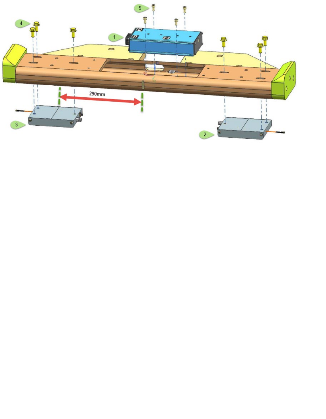
• Insert the antennas first through the top where the LIM is to be mounted
• NOTE: Left (JC-616) and right (JC-611) is determined from an operator’s perspective
• Also, the slots for the antennas are "keyed" differently to avoid an incorrect mounting
• NOTE: Attach both the coax and JC-611 / JC-616 to each antenna before bolting them to the
bumper
• Feed the plugs JC-623 & JC-626 through the opening at the back and center of the bumper
before mounting the LIM
• Secure the antennas ensuring that the measuring groove located on the top of the antenna is
290mm [Figure 1] from the center of the bumper
• Mount the LIM and connect the cables, ensuring the correct coax is associated with the
corresponding antenna
• Ensure that all the cables are free & clear before finally securing the LIM
APS RFID | Installation Guide
Figure 1 - Bumper Assembly
APS RFID | Installation Guide
3.2.1.1
Part Numbers & Torque Settings [Figure 1]
Figure #
Description
Quantity
Part Number
Torque Setting
1
LIM
1
153836-001
2
Antenna (Left)
1
155830-001
3
Antenna (Right)
1
155830-002
4
Screw (M8 x 20mm)
6
060063-050
11 – 14.5 Nm
5
Screw (M6 x 12mm)
4
060062-123
6 – 8 Nm
3.3
BUMPER INSTALLATION
3.3.1
Install New Bumper
• Positon the new bumper under the counter weights
• Connect the LIM bumper harness JC-623/JC-626 to the TSP LIM main harness PC-623/PC-626
• Attach the cable protection plate (part #?)
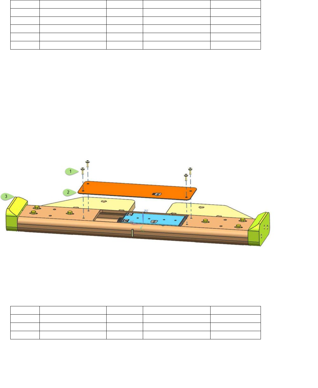
• Mount the cover plate and align the LED on the LIM to complete assembly [Figure 2]
Figure 2 - LIM Cover Plate
3.3.1.1
Part Numbers & Torque Settings [Figure 2]
Figure #
Description
Quantity
Part Number
Torque Setting
1
Screw (M6 x 16mm)
4
060062-002
4.5 – 6Nm
2
Cover plate
1
156090
3
RFID Bumper
1
156389-xxx
APS RFID | Installation Guide
3.3.2
Counter weight & cable routing
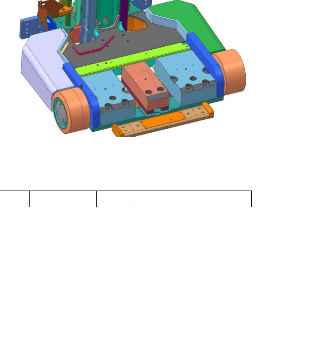
• Feed new harness through the center counter weight (if installed)
• Tighten the counter weight bolts and secure the new bumper
Figure 3 - Bumper Install
3.3.2.1
Part Numbers & Torque Settings [Figure 3]
Figure #
Description
Quantity
Part Number
Torque Setting
1
Screw M20
6
060099-004
359 Nm
APS RFID | Installation Guide
3.4
LIM POWER SUPPLY
3.4.1
Power Supply Mounting
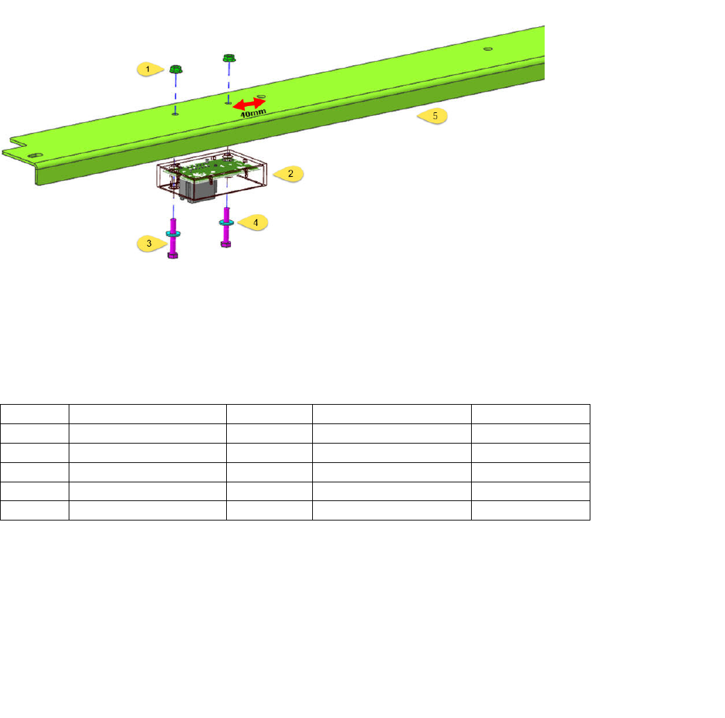
• Using the power supply as a template, mark and drill two M7 holes to mount the external power
supply to interior of the harness cover (Part # 133073)
• The first hole should be 40mm to the left of the first mounting hole [Figure 4]
• Plug PC-625 from the TSP LIM main harness into the power supply
• Using the supplied M6 nuts and bolts, mount the power supply to the interior of the harness
cover [Figure 4]
Figure 4 - Power Supply Mounting
3.4.1.1
Part Numbers & Torque Settings [Figure 4]
Figure #
Description
Quantity
Part Number
Torque Setting
1
Nut (M6)
2
060059-027
2
Power Supply
1
157650
3
Screw (M4 x 40mm)
2
050007-011
4.5 – 6Nm
4
Washer
2
060030-012
5
Cover
1
133073
APS RFID | Installation Guide
3.5
LOAD WHEEL ASSEMBLY
3.5.1
Tone Wheel Assembly
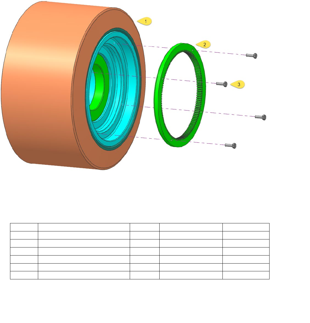
• This step is only required if the load wheel does not come pre-assembled
• Attach the tone wheel to the new load wheel assembly as shown in Figure 5
Figure 5 -Tone wheel assembly
3.5.1.1
Part Numbers & Torque Settings [Figure 5]
Figure #
Description
Quantity
Part Number
Torque Setting
1
Load Wheel Assembly
1
157101-???
a) Hub machined
1
157102
b) Bearing
1
065081-043
c) Wheel
1
133753-001/2
2
Tone Wheel
1
158965-???
3
Screw (M6 x 20mm)
4
060062-124
9 – 11 Nm
APS RFID | Installation Guide
3.5.2
Sensor Assembly
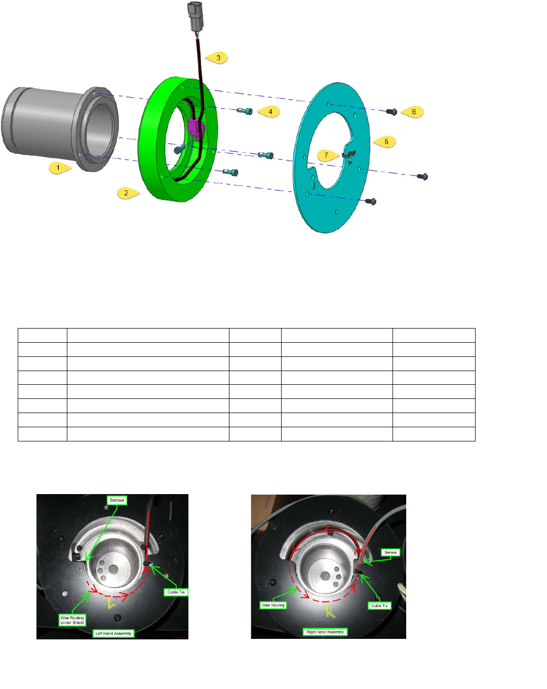
Figure 6 - Sleeve & Sensor assembly
3.5.2.1
Part Numbers & Torque Settings [Figure 6 – Sensor Assembly Part # 175105]
Figure #
Description
Quantity
Part Number
Torque Setting
1
Sensor Sleeve
1
156974
2
Sensor Mount
1
156975
3
Sensor
1
065196-003
4
Screw (M6 x 16mm)
4
060062-086
6 – 8 Nm
5
Shield
1
156973
6
Screw (M6 x 12mm)
3
060062-124
6 – 8 Nm
7
Wire Tie
1
061003-004
• Ensure that the sensor wires are routed and secured, as per the images below
APS RFID | Installation Guide
3.6
LOAD WHEEL INSTALLATION
3.6.1
Right Wheel
• Using a properly rated lift truck jack, raise the truck up off of the ground enough to remove
truck pressure on the right load wheel
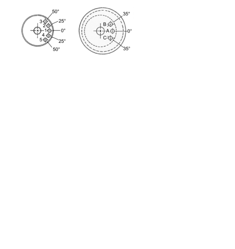
• Remove the hubcap and take note of the stamping on the load wheel:
o One character indicating which side of the truck the tire should be mounted on (R/L)
o One character indicating which bolt hole to use on the sleeve (1,2,3,4,5)
o One character indicating which hole to use on the load wheel itself
• Pull the current loadwheel off of the truck and place RFID load wheel onto the truck
• Before sliding the loadwheel entirely onto the axle, insert the odometry sensor plug through the
hole
• NOTE: Any TSP manufactured prior to April 2014 will not have this hole pre-drilled. You will
have to drill a hole at least 9mm thick to fit the cabling for the odometry sensor through
• NOTE: You may have to remove the connector to fit the plug between the outrigger and the
counterweight where this exists
• Once the cabling is pulled through you can push the load wheel all the way on, aligning the
proper holes on the loadwheel and axle to ensure proper height elevation and install the wheel
Mount the hubcap back onto the load wheel
• Plug the shorter of the two (PC-647) into the JC-647 from the right load wheel, leave the longer
(PC-624) under the cover plate [this may be required for a left load wheel sensor in the future]
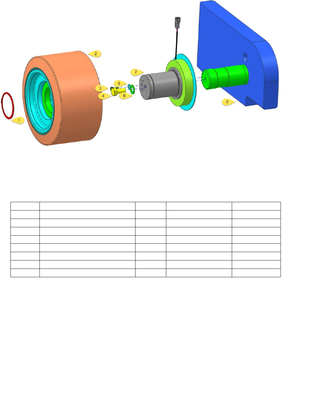
• Insert the assembled sensor sleeve into the new load wheel assembly
• Secure the load wheel assembly with the retaining clip
APS RFID | Installation Guide
3.6.2
Load Wheel Assembly
Figure 7 - Load Wheel / Sensor Assembly
3.6.2.1
Part Numbers & Torque Settings [Figure 7]
Figure #
Description
Quantity
Part Number
Torque Setting
1
Retaining clip
1
060009-115
2
Load wheel Assembly
1
157103
3
Screw M10
1
060075-025
?
4
Screw M20
1
060099-009
?
5
Flat washer
1
060030-026
6
Flat washer
1
060131-005
7
Sensor Assembly
1
157105
8
RH Mainframe Axle Support
1
APS RFID | Installation Guide
3.7
SOFTWARE AND WIRING
3.7.1
Update Truck Software
• NOTE: Before performing any wiring changes update the truck software using the standard
Crown download tool and the latest versions of firmware
• If InfoLink is installed ensure that the truck is in Maintenance mode to avoid any timeouts
• If you have any problems / delays in updating the truck software, temporally disconnect any
additional CAN devices like InfoLink / CAN keyboard etc for the update process
3.7.2
Wiring Harness Installation
• The TSP LIM main harness (part # 157533) should now be connected to the LIM Bumper
harness, routed through the center counter weight, connected to the load wheel sensor, and
connected to the power supply
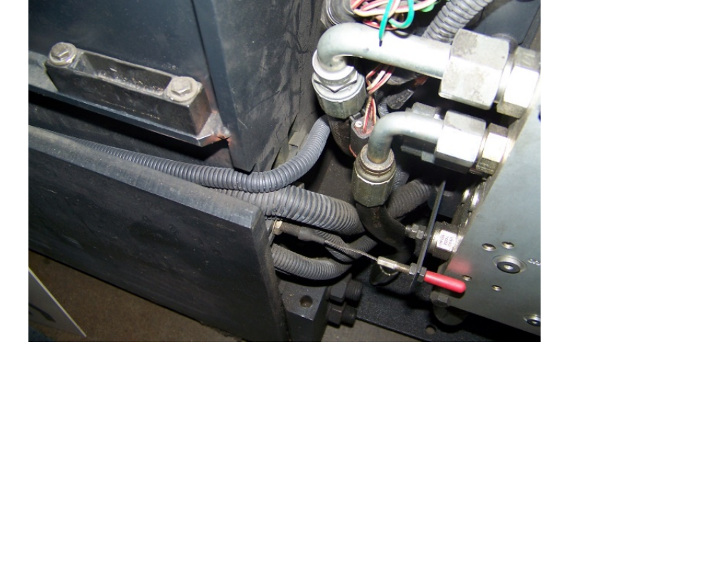
• Run the TSP LIM main harness in the channel along the right side of the truck where the
magnetic EAC harness typically runs
Figure 8 - Cable channel
• Leave JC-618 connector plug in right rear cavity of truck
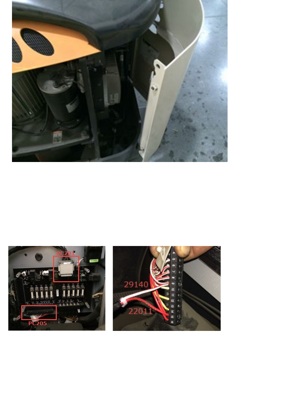
APS RFID | Installation Guide
Figure 9 - Right Rear Cavity of the Truck
• Install the LIM-RTM retrofit harness (Part # 175532):
a. Connect the solid Red wire (22011) to position 15 on PC-205
b. Connect the Red/White wire (29140) to position 9 on PC-205
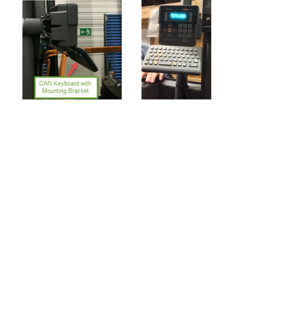
c. Connect the Negative wire (55116) to Negative bus bar [Figure 8]
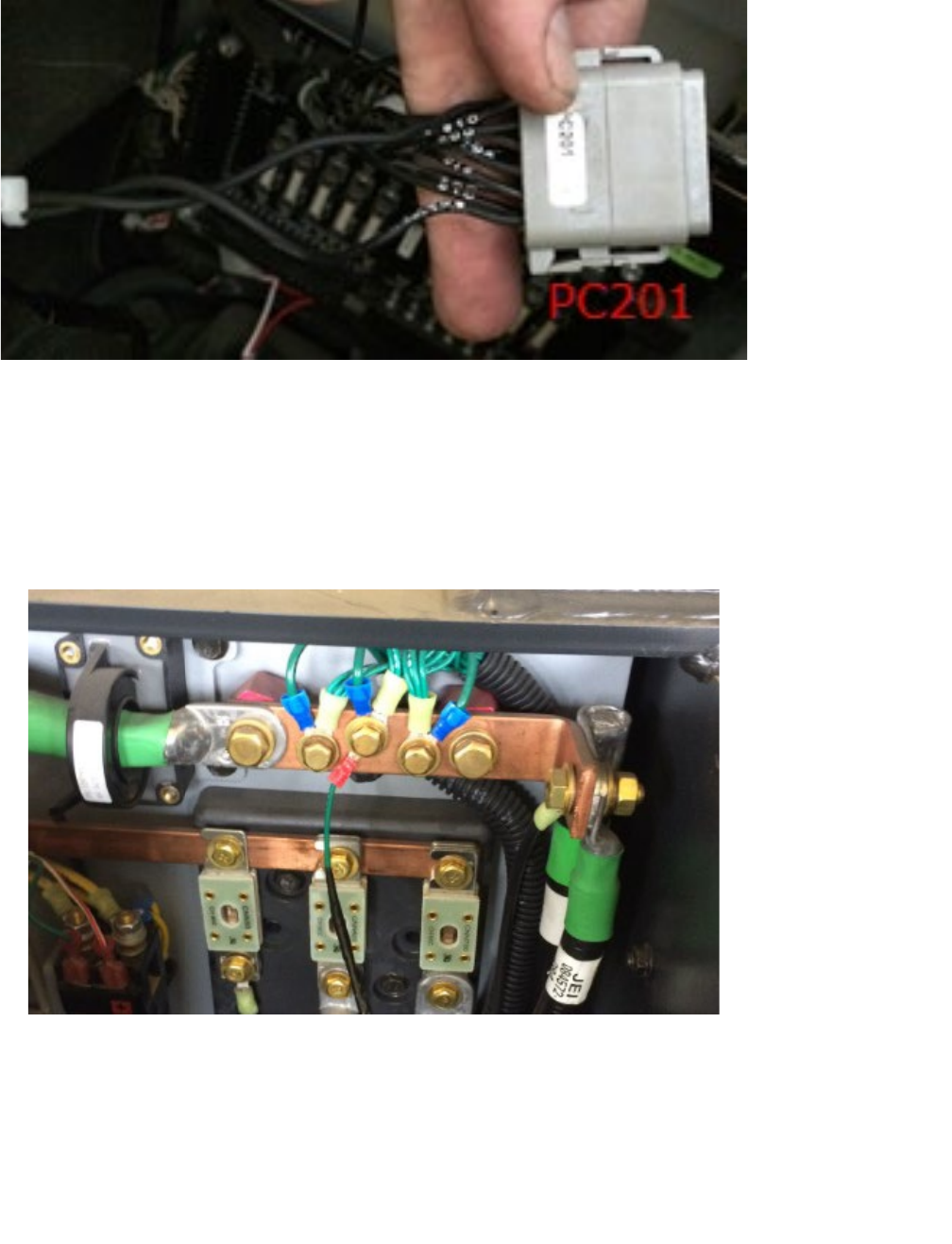
d. Connect CAN H (90012) and L (90011) to positions 12 and 6 respectively on PC-201
Figure 10 - Power Unit Distribution Panel & PC205
• If the truck is a TSP 6500 or 7000 these positions will be already in use by the CAN programming
plug on the truck. If this is the case, remove the wires existing wires in PC-201 and replace as
APS RFID | Installation Guide
per Step D above. The existing CAN programming plug is no longer required, as the new TSP
retrofit harness has one
Figure 11 - PC201
• Route PC-618 for the new TSP retrofit harness into the right rear cavity of the truck and connect
to JC-618
• After the retrofit harness is plugged in and power to the LIM is confirmed, install latest LIM code
using the standard Crown download tool.
Figure 12 - Negative Bus Bar
APS RFID | Installation Guide
3.8
CAN KEYBOARD
3.8.1
Keyboard Installation
• The CAN Keyboard should be mounted together with the HD2500 InfoLink Module onto a
bracket that is mounted to a work assist clamp. There are 4 bolts that mount the keyboard to
the bracket and the connector for the CAN Keyboard should align with the circular opening in
the back of the bracket.
3.8.2
Wiring Instructions
• The wire harness for the CAN keyboard will have the M5 connector coming out of the same
location as the InfoLink Harness. It will have the three colored wires coming in the opening
behind the key-switch where the 12 V power supply is located. It is easier to gain access to this
location by removing the bolts and raising the cover up and NOT removing the rubber
surrounding the key-switch:
a) Wire 33021 goes to the 12V output of the power supply behind the key switch on the
TSP.
b) 66009 goes to the ground of the 12V output of the power supply (the blue wire signifies
that it is an isolated ground that is isolated from the rest of the grounds on the truck
which are tied to battery negative)
c) 55122 goes to the ground of the 48V input to the power supply. This wire is tying the
truck ground (48V ground) to the isolated ground of the 12V output. This is done so
that the CAN lines all have a common ground connection. Otherwise, CAN
communication would have problems.
d) 90095 is CAN Low and goes to PC106-5. PC106 should be the gray 12-pin Deutsch plug
on the bottom back portion of the platform distribution panel.
e) 90096 is CAN High and goes to PC106-12.
f) PC796 is the M5 connector that connects to the keyboard.
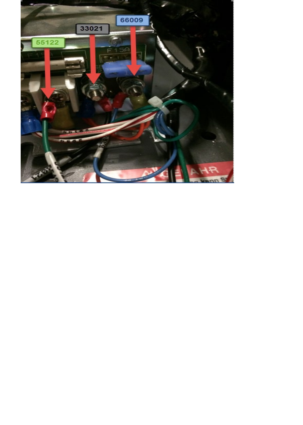
APS RFID | Installation Guide
Figure 13 - Power Inputs for CAN keyboard
3.9
MAP INSTALLATION
• Load the tag and slot map using the Short Term mapping tool
3.10
TRUCK CONFIGURATION
• Re-Key the truck and enter the Service Menu - Level 2
• Navigate to the Features Menu
• Navigate to F20 – End Aisle, and select NONE
• Navigate to F31 – RFID System
• Navigate to sub menu F31.3, and Enable EAC
• Save and Exit

APS RFID | Installation Guide
3.11
TRUCK COMMISSIONING
• Cycle the battery and key the truck on
• Check for event codes to confirm no CAN issues after completion & correct installation of the
new RFID solution
• Reference Appendix A for the truck event codes
3.12
CALIBRATION
• Re-Key the truck and enter the Service Menu - Level 2
• Lock onto the wire guidance with the right antenna lined up over the RFID tags in aisle.
• NOTE: Left and right is determined from a seated position in the cab looking out on the bumper
• Navigate to the Calibration menu
• Navigate to C6 – LIM Calibration
• Select the “Right Antenna”
• Follow the on screen instructions to perform the calibration
• Turn the truck around so that the left antenna is now lined up over the RFID tags
• Select the “Left antenna”
• Follow the on screen instructions to perform the calibration
• Save and Exit
3.13
TESTING
• Put the truck into the first aisle
• Lock onto the wire guidance
• Drive the first truck through all aisles in one direction to validate the tag map
• Drive all trucks through at least one aisle in both directions to validate both antennas

APS RFID | Installation Guide
4
APPENDIX
4.1
APPENDIX A – RFID EVENT CODES
682
LIM - Height/Speed Restriction Reaction Fault
683
LIM - Master/Supervisor Communication Fault
684
LIM - LIM Setup Fault
685
LIM - Tag Map Fault
686
LIM - Hardware Compatibility Fault
687
LIM - Software Compatibility Fault
688
LIM - Load Wheel Fault
689
LIM - Left Antenna Fault
690
LIM - Right Antenna Fault
691
LIM - Missing Tag Fault
692
LIM - Impinj Fault
693
LIM - Serial Fault
694
LIM - FRAM Fault
695
LIM - Lost Access 4 PDOs
696
LIM - Lost Access 7 PDOs
697
LIM - Lost Access 5 PDOs
698
LIM - Lost Access 6 PDOs